

Page 1

1
OUTLINE
1 OUTLINE
Page 2
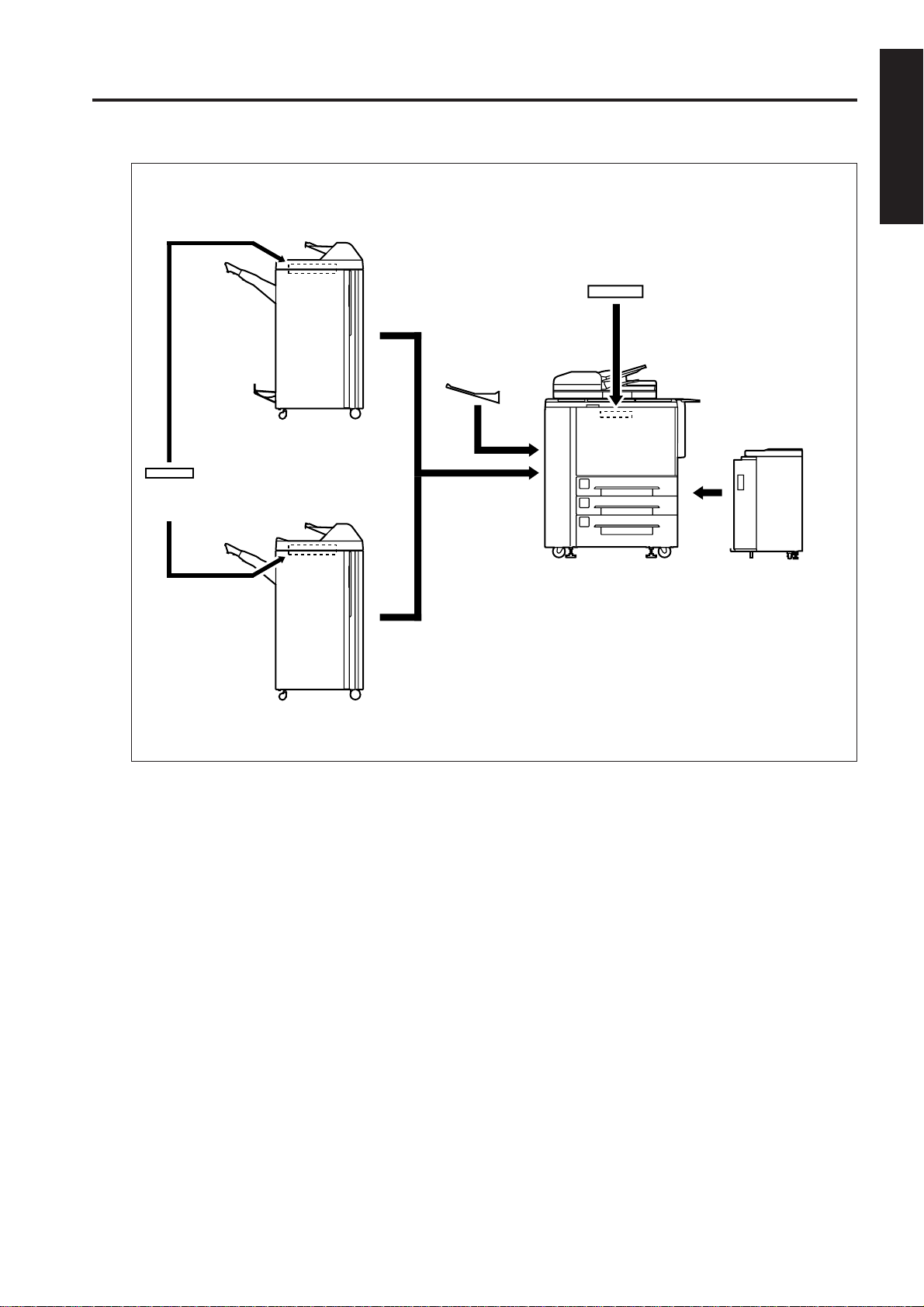
OUTLINE OF SYSTEM
Finisher
[FS-108BM]
Post Inserter
[PI-108]
MAIN BODY
1 OUTLINE
Expansion memory unit
[MU-401/402]
Paper exit tray
Finisher
[FS-108]
4000-sheet LCT
[LT-401]
1 - 1
Page 3

7075 PRODUCT SPECIFICATIONS
7075 PRODUCT SPECIFICATIONS
1. T ype
1 OUTLINE
Installation Type:
Copying method:
Document tray type:
Photosensitive material:
Sensitizing method:
Paper feed trays:
2. Functions
Applicable document types:
Document size:
Copy paper size:
Magnifications
Fixed magnifications:
Special ratio magnifications:
Vertical magnifications:
Horizontal magnifications:
Console type (floor-mounted type)
Indirect electrostatic method
Fixed
OPC
Laser writing
Three stacked trays (two for 500
sheets of 80 g/m2 paper; one for
1000 sheets of 80 g/m2 paper)
A by-pass tray for various paper
sizes (150 sheets of 80 g/m2 paper)
LCT (4000 sheets of 80 g/m
paper)*1
*1: Optional
Sheets, book, solid object
A3 max.
A3 to A5
11x17 to 8.5x11, F4
x1.00, x2.00, x1.41, x1.22, x1.15,
x0.86, x0.82, x0.71, x0.50
3 modes
x0.33 to x4.00 (400 dpi, in 1% steps)
x0.33 to x2.00 (600 dpi, in 1% steps)
x0.33 to x4.00 (400 dpi, in 1% steps)
x0.33 to x2.00 (600 dpi, in 1% steps)
First copy out time:
3.9 seconds or less (for A4, manual
copy density selection, straight
paper ejection with the copied image
facing up, platen mode, life size,
paper feed from tray 1)
Continuous copy speed (life size, copies/
min):
Size cpm
A4 75
Continuous copy count:
1 to 9999
Copy density selections:
AE, manual
Arbitrary density (2 modes)
2
E-RDH memory capacity:
standard 64MB
maximum 512MB
Special functions:
Interleaves, chapter , combination (2
in 1, 4 in 1, 8 in 1), booklet, OHP
interleave, image insertion, book
copy, automatic tray selection for
mixed sized document, special
document (text, photo, pencil),
reversed image, repeated copy,
frame/fold erase, auto layout, thin/
thick paper, shift/reduction shift, nonimage area erase, memory copy,
density monitoring, single step copy ,
density shift, printing function, copy
reservation, image rotation, weekly
timer, job memory, interrupts, auto
power sav e, auto reset, auto shutoff,
SDF function, EKC.
*2: 6 minutes is the machine for the
230VAC specification.
Warm-up time differs depending
on the Power source (voltage).
Warm-up time:
Less than 6 minutes*2
1 - 2
Page 4
MAIN BODY
3. Applicable Copy Paper
Plain paper:
High quality paper 60 g/m2 to 90 g/m
Special paper (bypass feed only):
Tabs
OHP film
Blueprint master paper
Recycled paper
High quality plain paper (50 g/m2 to
59 g/m2, 91g/m2 to 200 g/m2)
4. Options
Finisher: FS-108, FS-108BM
4000-sheets LCT: LT-401
Expantion memory unit:
MU-401: 64MB
MU-402: 128MB
Post inserter: PI-108
Paper exit tray
5. Particulars of Machine
Power supply:
230 VAC -14% to 10.6%
50 Hz/60 Hz
Power consumption:
2850W max.
(with LT-401)
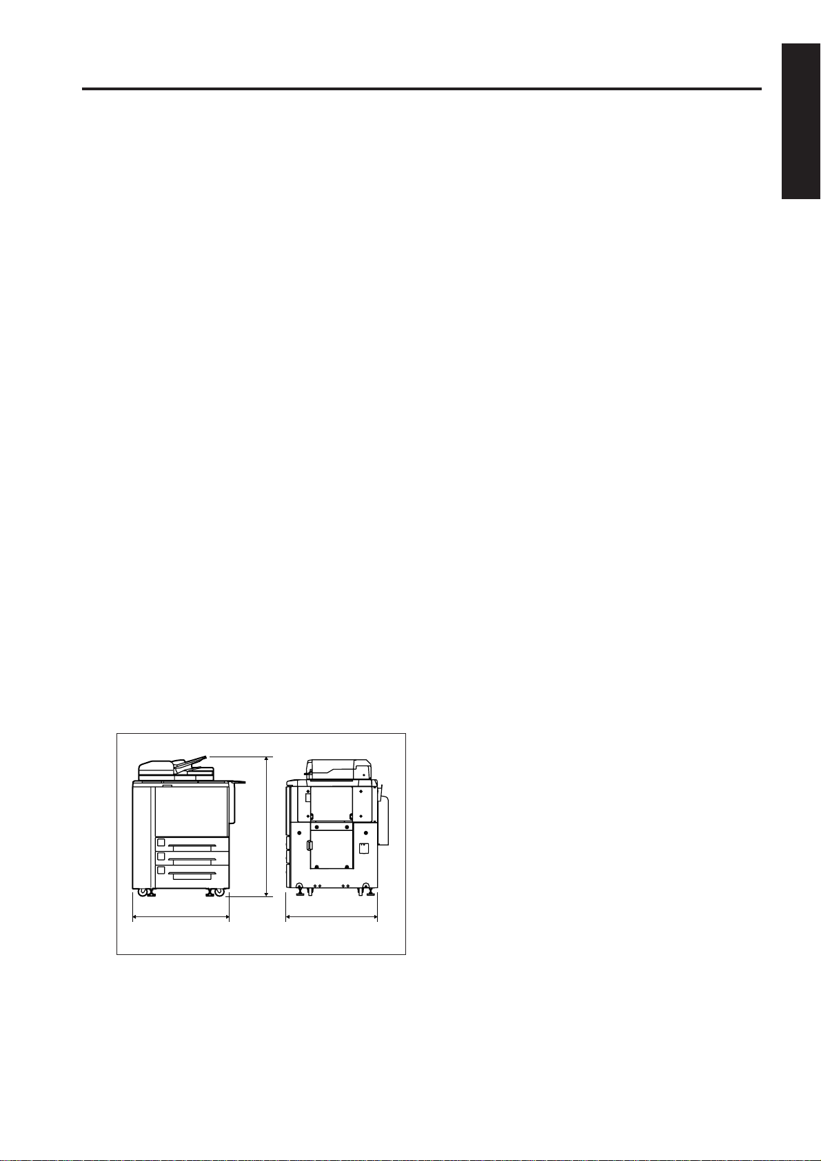
Weight: Approx. 280 kg
Machine dimensions:
6. Maintenance and Life
1 OUTLINE
Periodic maintenance:
2
Every 250,000 copies
Machine life:
30,000,000 copies or 5 years
7. Consumables
Developer: Exclusively for Konica 7075
Toner : Exclusively for Konica 7075
Drum: Exclusively for Konica 7075 (ø100)
8. Environmental Conditions
Temperature:
10°C to 30°C (50°F to 86°F)
Humidity: 10% to 80% RH
The information herein may subject
to change for improvement without
notice.
887 mm
1203 mm
775 mm
1 - 3
Page 5
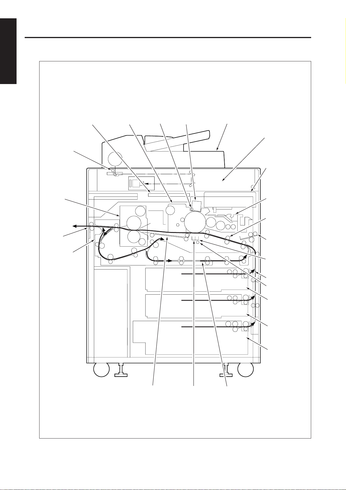
MAIN UNIT
CENTER CROSS-SECTIONAL VIEW
1 OUTLINE
Image processing
section
Exposure lamp
Fixing
section
Paper exit
section
Paper reverse/
exit section
Cleaning section
PCL
Charging corona
section
RADF
Image read
section
Image write
section
Developing
section
Second paper
feed
section
By-pass tray
Transfer corona
section
Vertical conveyance
section
TSL
Paper conveyance
section
1 - 4
Separation
corona section
Tr a y 1
Tr a y 2
Tr a y 3
ADU
Page 6
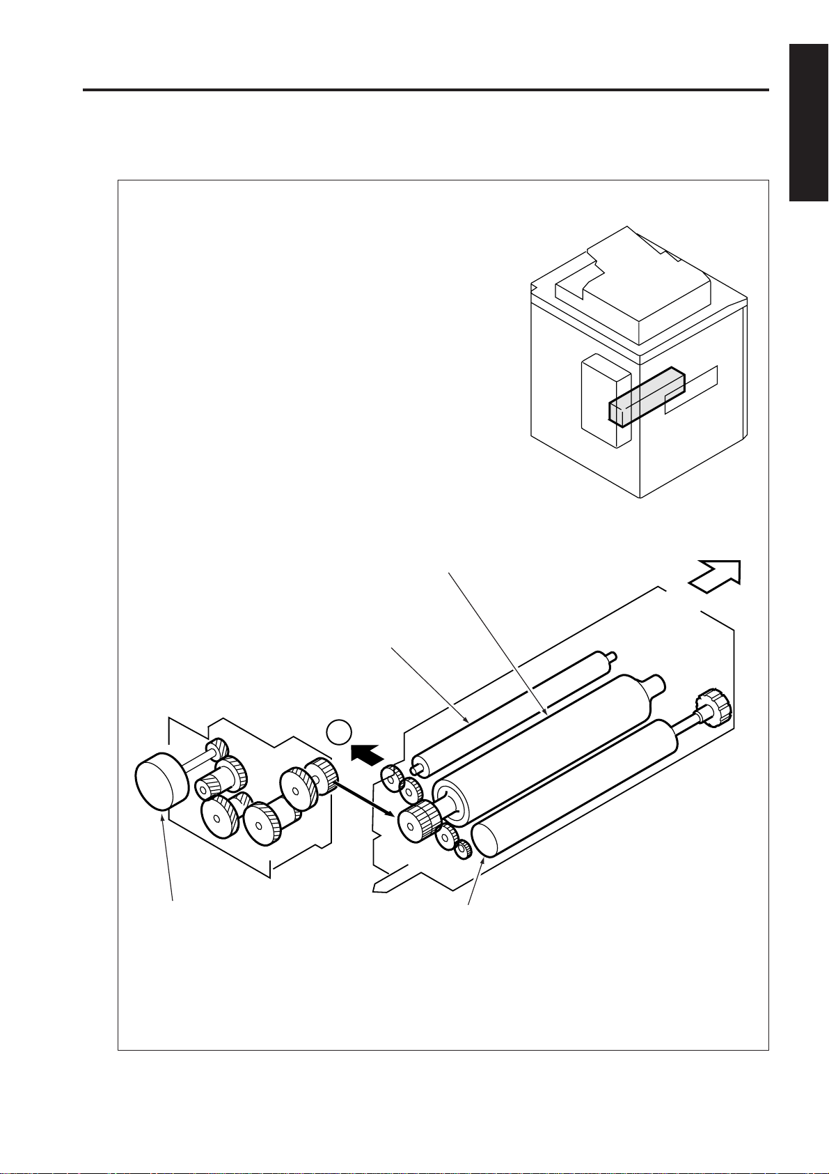
DRIVE SYSTEM DIAGRAM
MAIN BODY
[1] Main Drive Section
1 OUTLINE
FRONT
Fixing unit
upper roller
Main motor (M1)
Fixing unit
Heating roller
To paper conveyance and
transfer/separation corona
cleaning section
1
Fixing unit lower roller
1 - 5
Page 7

MAIN BODY
1 OUTLINE
[2] Drum Drive Section
FRONT
Drum
motor (M2)
Separation claw
solenoid (SD4)
Drum
Toner
guide
brush
Toner guide
shaft
Toner conveyance
screws
Separation claw unit
Separation claw swing cam
1 - 6
Page 8

MAIN BODY
[3] Developing Drive Section
1 OUTLINE
FRONT
Developing motor (M3)
Agitator screw
Agitator wheel
Developing sleeve
1 - 7
Page 9

MAIN BODY
1 OUTLINE
[4] Paper Feed Drive Section
5
6
To vertical conveyance section
To vertical conveyance section
To tray 1 paper feed/
2
tray up drive section
3
To tray 3 paper feed/
4
tray up drive section
FRONT
To tray 2 paper feed/
tray up drive section
Paper feed motor (M4)
1 - 8
Page 10

MAIN BODY
[5] Tray 1 and 2 Paper Feed Drive Section
1 OUTLINE
Tray up motor 1/2 (M19/M20)
Pre-registration MC1/2
(MC4/MC6)
2
3
From paper feed
drive section
Feed roller
Pre-feed registration roller
Feed MC1/2 (MC3/MC5)
FRONT
Paper feed roller
Double feed
prevention roller
1 - 9
Page 11

MAIN UNIT
1 OUTLINE
[6] Tray 3 Paper Feed Drive Section
Pre-feed registration roller
Pre-registration MC3
(MC8)
4
From paper feed drive
section
Feed roller
FRONT
Tray up motor 3 (M21)
Paper feed roller
Double feed
prevention roller
Feed MC3 (MC7)
1 - 10
Page 12

MAIN BODY
[7] Vertical Conveyance Drive Section
1 OUTLINE
FRONT
Vertical
conveyance
MC1 (MC9)
Vertical
conveyance
MC2 (MC10)
From bypass
paper feed drive
7
section
From paper
feed drive
5
section
From paper
feed drive
6
section
Vertical conveyance
roller (Upper)
Vertical conveyance
roller (Middle)
Vertical conveyance
roller (Lower)
1 - 11
Page 13

MAIN BODY
1 OUTLINE
[8] By-pass Paper Feed Drive Section
Tray up/down motor (by-pass tray: M22)
Paper feed roller
To ADU conveyance
8
drive section
FRONT
Feed roller
Loop roller motor (M6)
7
To vertical conveyance
1 - 12
Page 14

MAIN BODY
[9] Conveyance/Transfer and Separation Wire Cleaning Drive Section
1 OUTLINE
Transfer/separation cleaning motor (M18)
Thick paper conveyance rollers
1
From main drive section
FRONT
Conveyance belts
1 - 13
Page 15

MAIN BODY
1 OUTLINE
[10] ADU Conveyance Drive Section
Loop roller
Registration roller
Registration MC
(MC1)
Registration motor
(M12)
ADU exit roller
8
From by-pass
paper feed
drive section
Pre-registration roller
Pre-transfer roller
ADU horizontal
conveyance roller 2
ADU pre-registration
MC (MC2)
Transfer motor (M9)
From fixing
unit drive
FRONT
ADU conveyance motor (M8)
ADU reverse roller
ADU reverse motor (M7)
Paper reverse/exit
motor (M5)
Paper reverse/
exit roller 1
Pre-registration loop roller
ADU horizontal
conveyance roller 1
1 - 14
Paper reverse/exit
entrance roller
Paper reverse/
exit roller 2
Paper reverse/exit roller 3
Page 16

MAIN BODY
[11] Paper Exit Drive Section
1 OUTLINE
Paper exit motor (M10)
FRONT
Paper exit roller
1 - 15
Page 17

MAIN BODY
1 OUTLINE
[12] Toner Supply Drive
Toner supply motor 1 (M11)
Toner supply motor 2 (M15)
FRONT
Toner cartridge
1 - 16
Page 18

MAIN BODY
[13] Optics Drive Section
First mirror
1 OUTLINE
Slit-glass
FRONT
Scanner drive motor
(M13)
Second mirror
Third mirror
Optics wire (Rear)
Optics wire (Front)
1 - 17
Page 19

MAIN BODY
1 OUTLINE
[14] Web Drive Section
Web drive motor (M16)
FRONT
Cleaning web
1 - 18
 Loading...