

Page 1

1
ADJUSTMENT
1 ADJUSTMENT
Page 2

HOW TO USE THIS SECTION
ADJUSTMENT
[1] Scope and Precautions
This section provides detailed information about the
adjustment items and procedures. Before addressing
customer complaints, perform the following checks:
1. Check whether the power supply voltage meets
the specifications.
2. Check whether the power supply is properly
grounded.
3. Check whether this machine shares the power
supply with any other machine that draws large
current intermittently (e.g., elevator and air
conditioner that produce electrical noise).
4. Check whether the installation environment is
good.
a. The machine must be installed in a properly
ventilated area not exposed to high
temperature, high humidity , and direct sunlight.
b. The machine must be installed on the
horizontal floor.
5. Check whether original has a problem to cause
the defective image.
6. Check whether the selected density value is
correct.
7. Check whether the surface of the platen glass
and the bottom of the RADF are clean.
8. Check whether correct paper is used for cop ying.
9. Check whether copying materials and parts (e.g.,
developer, drum, and cleaning blade) are
replenished and replaced when they reach the
end of the useful life.
10. Check whether toner remains.
4. T ak e care not to damage the drum with tools and
so on.
5. Do not touch IC pins with bare hands.
1 ADJUSTMENT
When servicing the machine, observe the following
precautions:
1. Only either side of the AC line is shut off when
the main power of this machine is turned off.
Always unplug the power cord bef ore starting the
service work. If it is necessary to service the
machine with the power on, take care not to be
caught in the scanning gear of the exposure unit.
2. Special care should be taken when handling the
fixing unit because it operates at extremely high
temperatures.
3. The developing unit has a strong magnetic field.
Keep watches and measuring equipment away
from it.
1 - 1
Page 3

ADJUSTMENT
ADJUSTMENTS MADE WHEN REPLACING PARTS
Adjustments (including checks) and settings are not
only required when a customer complaint about the
1 ADJUSTMENT
copy image quality is received, b ut also after replacing
or reassembling parts.
[How to Read Tables]
Components of the tables used in this section are as
follows:
1. Mode
Adjustment mode to be selected.
[P] : P mode
[25] : 25 mode
[36] : 36 mode
[47] : 47 mode
2. Code
Code and copy quantity setting button used in
each mode.
3. Page
Page in the “ADJUSTMENT” section.
4. Circled numbers
1 , 2 …: Indicates adjustments (including
checks) must be made in order of precedence.
(Circle without numeric character) :
Indicates adjustments (including
checks) can be made independently.
1 - 2
Page 4
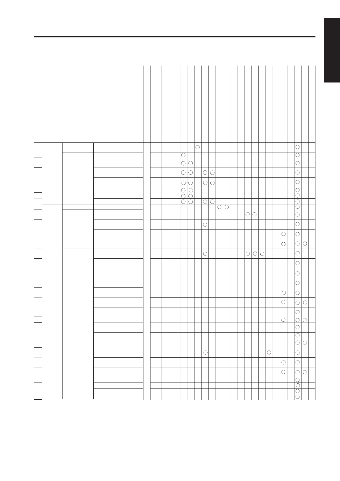
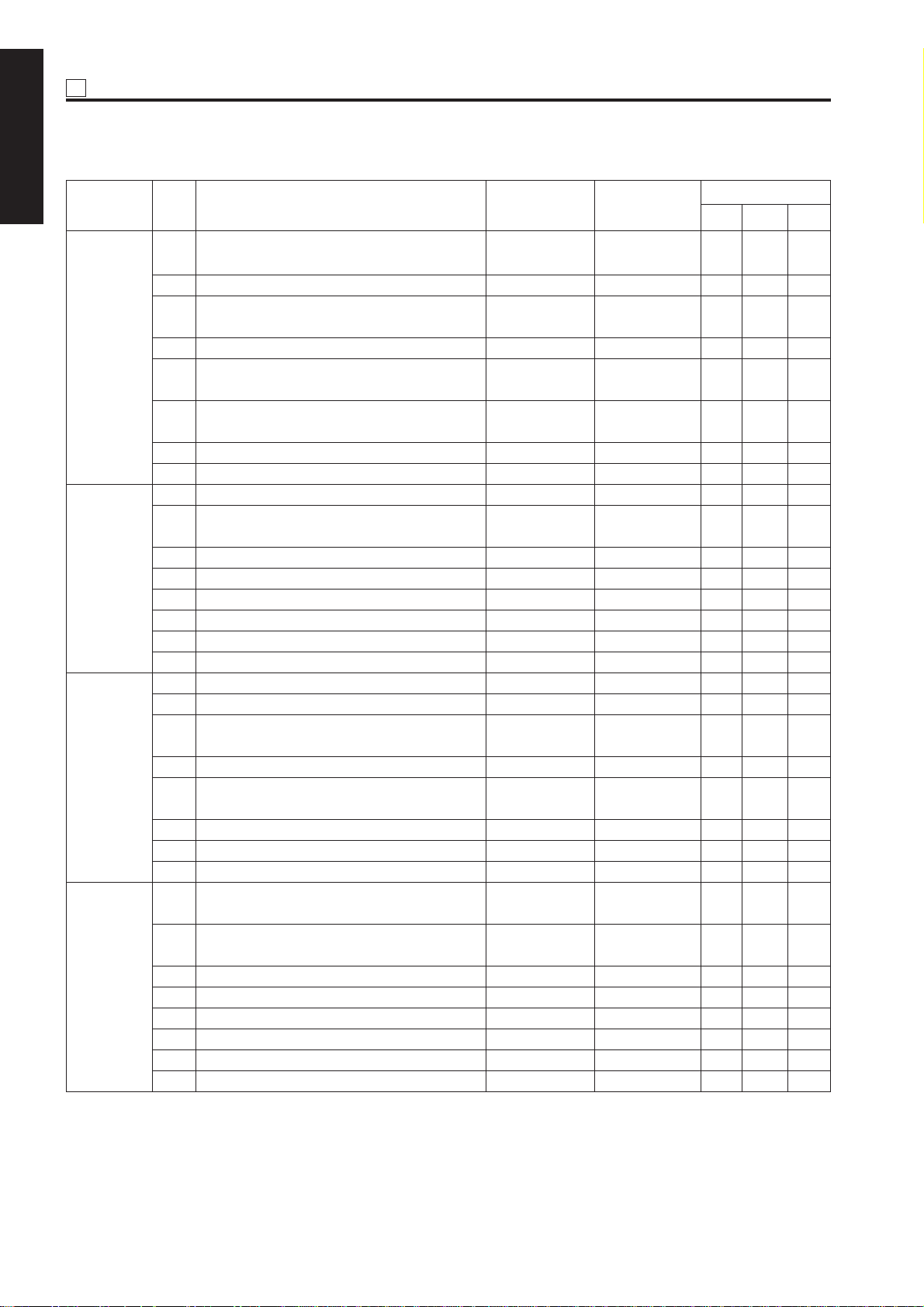
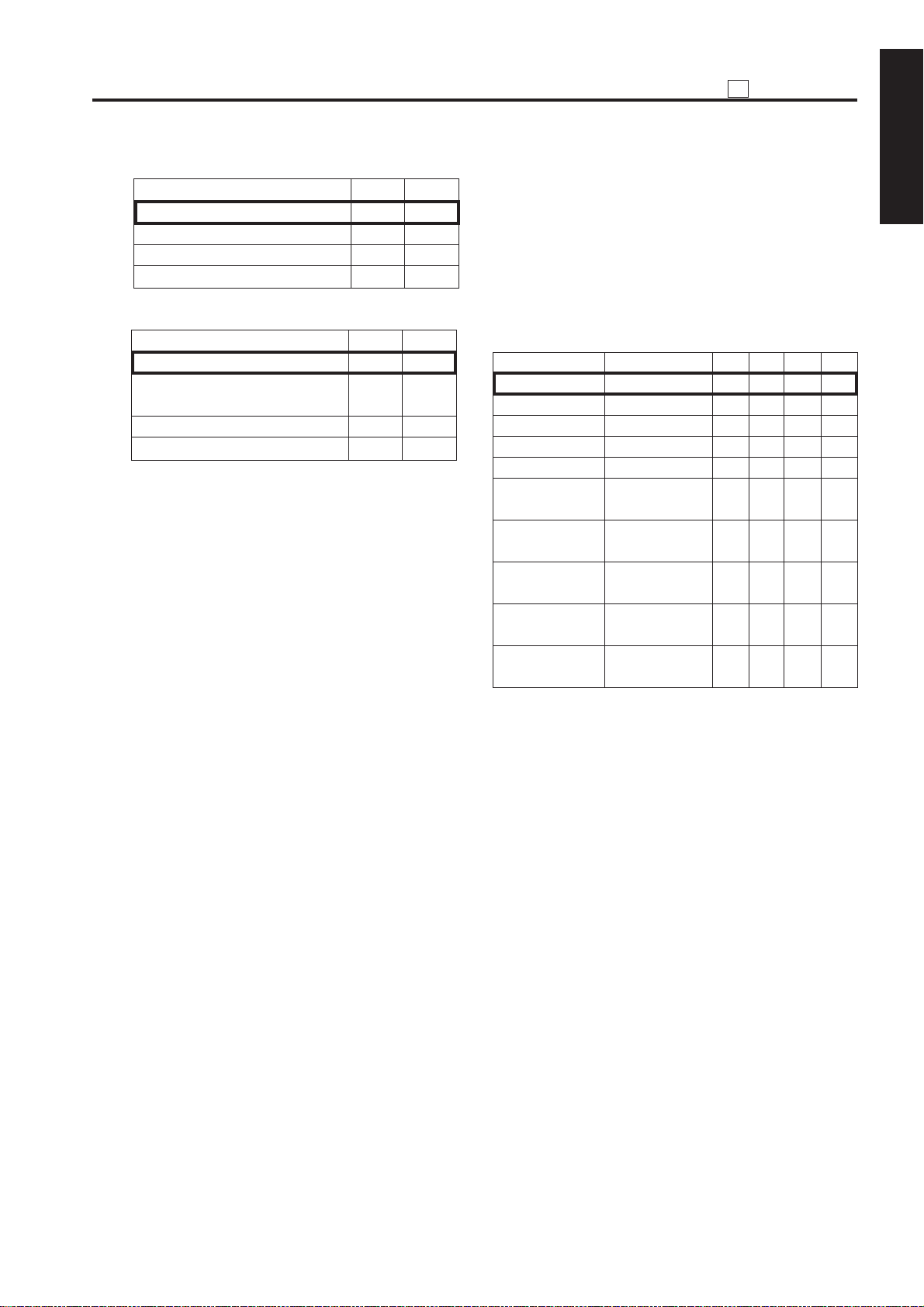
LIST OF ADJUSTMENT ITEMS
Developer
Drum
Page
Code
Mode
Bypass paper feed unit
Each tray unit
Dust-proof glass
Write unit
High voltage unit
ADJUSTMENT
Fixing unit
Read unit
ADU unit
Mis-centering detection sensor
Registration dutch
Registration unit
Registration roller
Tray pick-up solenoid
Paper up/down plate hoist wires
Finisher
RADF unit
Memory board
1 ADJUSTMENT
1
2
3
4
5
6
7
8
9
10
11
12
13
14
15
16
17
18
19
20
21
22
23
24
25
26
27
28
29
30
31
Process
adjustment
Image
adjustment
High voltage
adjustment
Drum peculiarity
adjustment
Tray adjustment
Magnification
adjustment
Timing
adjustment
RADF
adjustment
Centering
adjustment
War p
adjustment
(Copier)
High voltage auto
adjustment
Blade setting mode
Auto drum potential
adjustment
Auto maximum density
adjustment
Auto dot diameter
adjustment
LD1 offset adjustment
LD2 offset adjustment
Auto gamma adjustment
Printer drum clock
adjustment
Printer horizontal
adjustment
Scanner drum clock
adjustment
RADF drum clock
adjustment
Printer restart timing
adjustment
Printer resist loop
adjustment
Printer pre-resist
adjustment
Printer lead edge timing
adjustment
Scanner restart timing
adjustment
RADF restart timing
adjustment
RADF resist loop
adjustment
RADF density adjustment
RADF original size
adjustment
RADF sensitivity adjustment
RADF incline offset
adjustment
Printer centering
adjustment
Scanner centering
adjustment
RADF centering
adjustment
Scanner (platen) warp adj. (Main)
Scanner (platen) warp adj. (Deputy)
Scanner (RADF) warp adj. (Main)
Scanner (RADF) warp adj. (Deputy)
1-1-1 1-67
1-2-1 1-68
1-2-2 1-69
1-2-3 1-69
1-2-4 1-70
1-2-5 1-70
1-2-6 1-71
1-2-7 1-72
2-1 1-73
2-3-1 1-74
2-3-2 1-75
2-3-3 1-75
2-3-4 1-76
2-4-1 1-77
2-4-2 1-78
36 2-4-3 1-78
2-4-4 1-79
2-4-5 1-79
2-4-6 1-80
2-4-7 1-80
2-5-1 1-81
2-5-2 1-82
2-5-3 1-82
2-5-4 1-83
2-6-1 1-84
2-6-2 1-84
2-6-3 1-85
2-8 1-85
2-8 1-85
2-8 1-85
2-8 1-85
1
21
32 22
43 11
54
65
76 33
()
()
()
()
1 - 3
Page 5
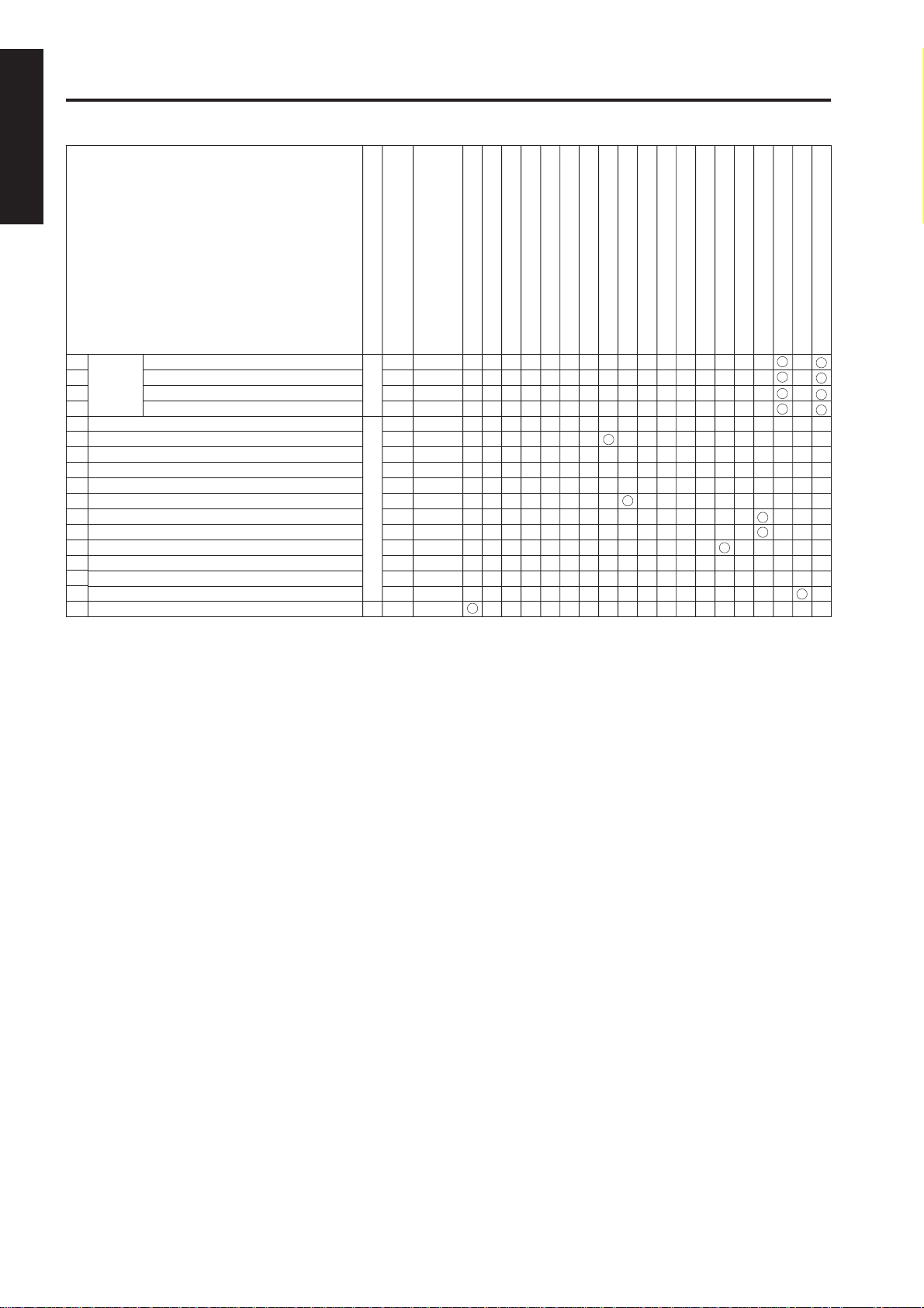
ADJUSTMENT
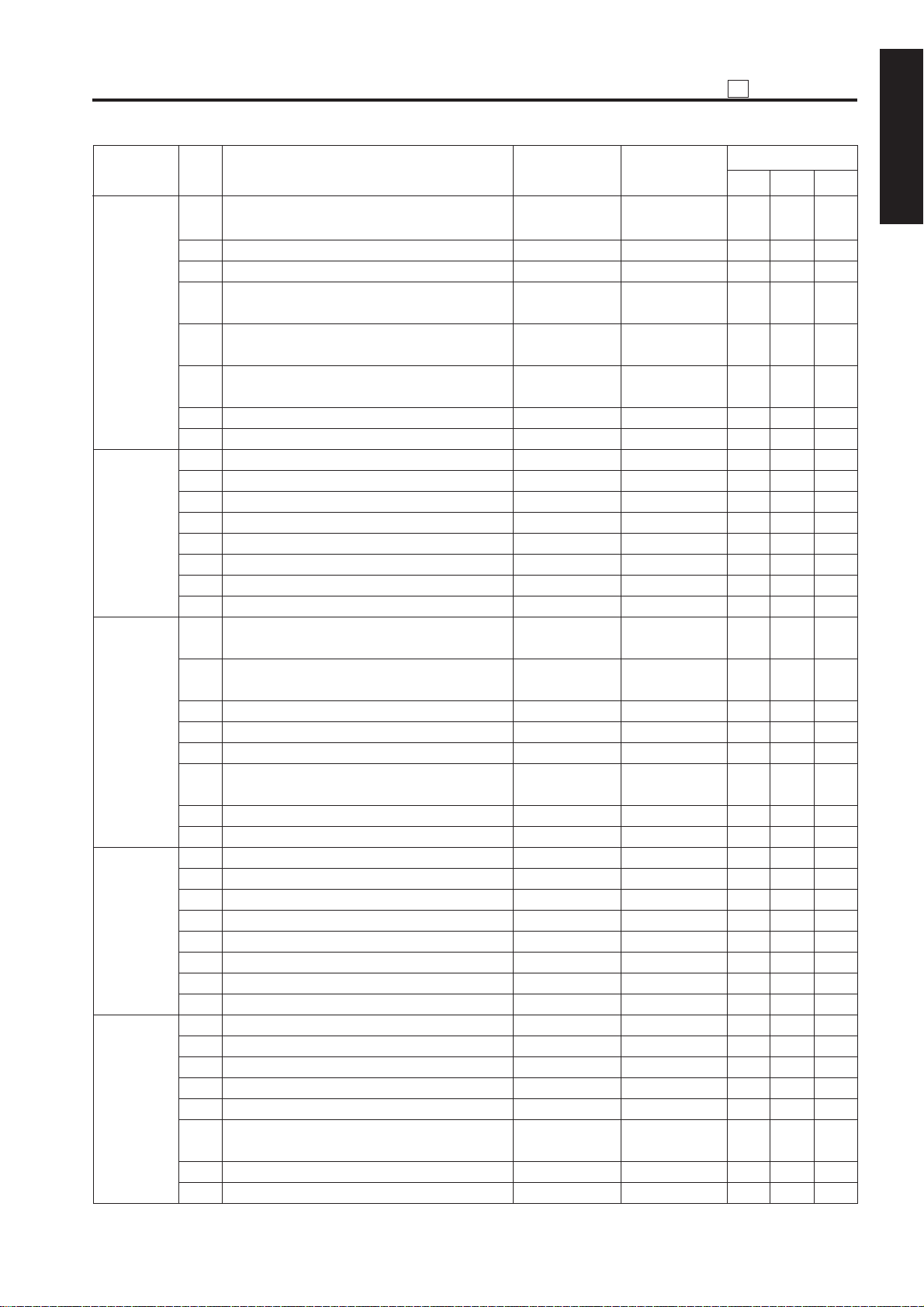
1 ADJUSTMENT
Mode
Code
Page
High voltage unit
Toner (developer)
Drum
Bypass paper feed unit
Each tray unit
Dust-proof glass
Write unit
ADU unit
Mis-centering detection sensor
Registration dutch
Registration unit
Registration roller
Tray pick-up roller unit drive solenoid
Paper up/down plate wires
Memory board
Fixing unit
Read unit
Finisher
RADF unit
Finisher
32
adjustment
33
34
35
Tray centering adjustment
36
37
Paper up/down plate horizontal adjustment
38
Skew adjustment
39
Tray spring pressure adjustment
40
Paper feed height (upper limit) adjustment
41
Pick-up release amount adjustment
42
Alignment with pickup unit
43
AC and DC drawer positioning
44
ADU gate gap adjustment
45
RADF mountng position adjustment
46
RADF hinge spring pressure adjustment
47
RADF distortion adjustment
48
Drum count reset
Center bind stopper position adjustment
Center fold stopper position adjustment
Cover sheet tray size adjustment
Cutting stopper position adjustment
6-1
6-2
36
6-4 1-145
1-107~108
1-110~111
1-112
-113~114
1
1-114~116
1-117~118
1-119
1-123
25 5-1-3 1-40~41
* When adjustments must be made in order of precedence, numbers will be shown in circles.
Cautions:
• When a damaged control board is replaced, the memory board on this board must be used on the
new control board.
Only when the memory board is also damaged, use a new memory board on a new control board.
Since the new memory board does not have adjustment data, the above adjustments are required.
Before making the above adjustments, make the “47-92” setting to make the new memory board
effective.
• After making any adjustment, make the “”47-96" setting so that this adjustment value can be restored simply by making the “47-93” setting even if another adjustment is made later.
• Various adjustments (stapling stopper position adjustment, f olding stopper position adjustment) must
be made to the FNS (FS-108BM) and an adjustment (cover sheet tray size adjustment) must be
made to the PI (PI-108).
1 - 4
Page 6

LCD ADJUSTMENT
LCD
ADJUSTMENT
[1] LCD Touch Panel Adjustment
Enter the key operator mode and select "10: LCD touch
panel adjustment" to adjust the LCD touch panel.
If you cannot select the touch panel adjustment mode
after entering the key operator mode because the touch
panel is displaced absolutely, press numeric keys to
select "10: LCD touch panel adjustment."
[2] LCD Contrast/Buzzer Adjustment
Enter the key operator mode and select "7: LCD
contrast/buzzer adjustment" to adjust the contrast,
backlight, and/or buzzer as desired.
1 ADJUSTMENT
1 - 5
Page 7
P ADJUSTMENT
SETTINGS AND
ADJUSTMENTS MADE
1 ADJUSTMENT
WITH THE P FUNCTION
The P function allows you to perform following checks
using the P button:
• Total counter
• Copy counter
• Print counter
* PM counter
* PM counter is only displayed when Check key
is pressed on the counter list view screen.
This section explains the checks that can be perf ormed
by customer engineers. For the checks that can be
performed by customers, see the “OPERATION”
section.
[1] Selecting and Canceling the P
Function
a. Turn ON the main switch.
b. Press the P button.
c. Counter list is displayed.
d. Using the quantity setting button, enter the
desired number according to the message
displayed on the operation panel.
e. Press the START PRINT button to check the
data displayed in the message area, or output
user data.
f. Press the End button.
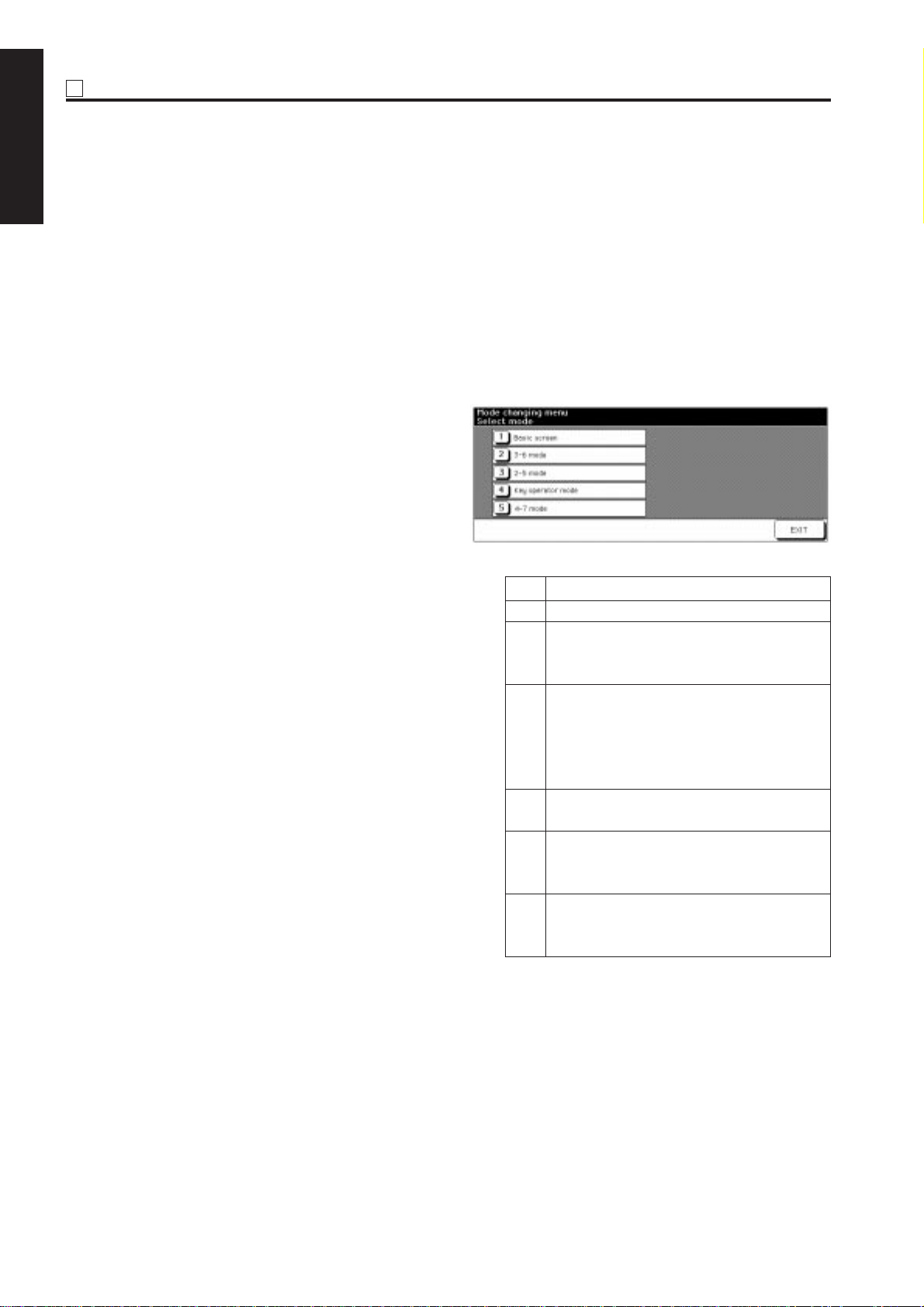
MODE CHANGING MENU
[1] Mode Selection
You can select a mode from the f ollo wing [Mode
changing menu: Select mode] without turning
OFF and ON the power switch.
[1 ] Basic screen
[2 ] 3-6 mode
[3] 2-5 mode
[4] Key operation mode
[5] 4-7 mode
Step Operation
1 Turn on the main power switch.
2 Press P button and wait until [Enter
password for mode selection] message
appears.
3 Enter the password 9272 and press the
Copy button.
Note that this password is fix ed and can
not be changed.
The Mode changing menu appears.
4 Enter the number to select the desired
mode.
5 To return to the [Mode changing menu],
press P button and wait until the menu
appears again.
6 Upon completion of the adjustment,
press [1] Basic screen button to return
to the Basic screen.
1 - 6
Page 8
25 MODE
25
ADJUSTMENT
[1] Selecting and Canceling the 25
Mode
This machine has an adjustment mode called the “25
Mode.” Select this mode to rewrite data in the nonvolatile memory or make various settings.
1. Turn OFF the main switch.
2. While pressing the copy quantity setting buttons 2
and 5, turn ON the main switch.
The 25 Mode Menu screen will appear.
Now the machine is in the 25 mode, disabling normal
copy operations.
[25 Mode Menu screen]
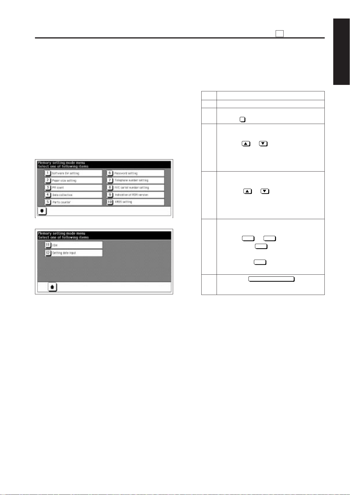
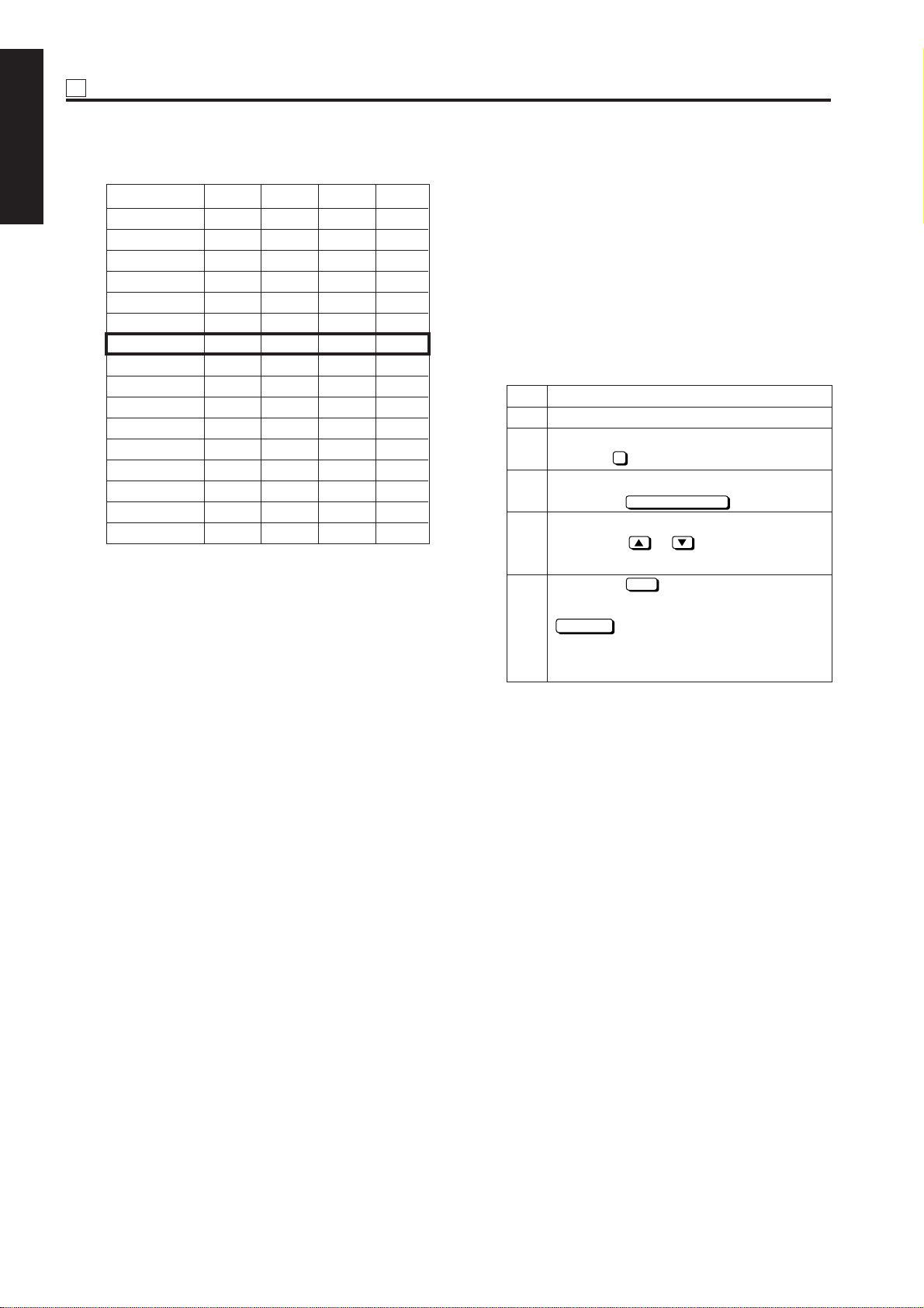
[2] Setting Software DIP Switches
1. Procedure
Bring up the Software DIP SW Setting screen
and set software DIP switches.
Step Operation
1 Enter the 25 mode.
2 [25 Mode Menu Screen]
Select 1 Software DIP SW setting.
3 [Software DIP SW Setting Screen]
Select a DIP switch number.
Use the or button at the left.
To use numeric keys, invert the DIP
switch number at the left before entering
a DIP switch number.
4 Select a bit number of the selected DIP
switch.
Use the or button at the right.
To use numeric keys, invert the bit
number at the upper center before
entering a DIP switch number.
5 Select ON (= 1) or OFF (= 0) of the
switch.
Use the
Pressing the
bit.
Pressing the
bit.
6 Press the
return to the 25 Mode Menu screen.
ON
OFF
or
ON
OFF
PREVIOUS SCREEN
button.
button turns ON the
button turns OFF the
button to
1 ADJUSTMENT
3. Press the numeric button of the desired setting
item.
The associated setting screen will appear.
4. Enter data in the setting screen.
5. Turning OFF the main switch cancels the 25
mode.
6. New data will take effect after restart.
For functions of individual software DIP switches,
see “List of Software Switches.”
1 - 7
Page 9
25 ADJUSTMENT
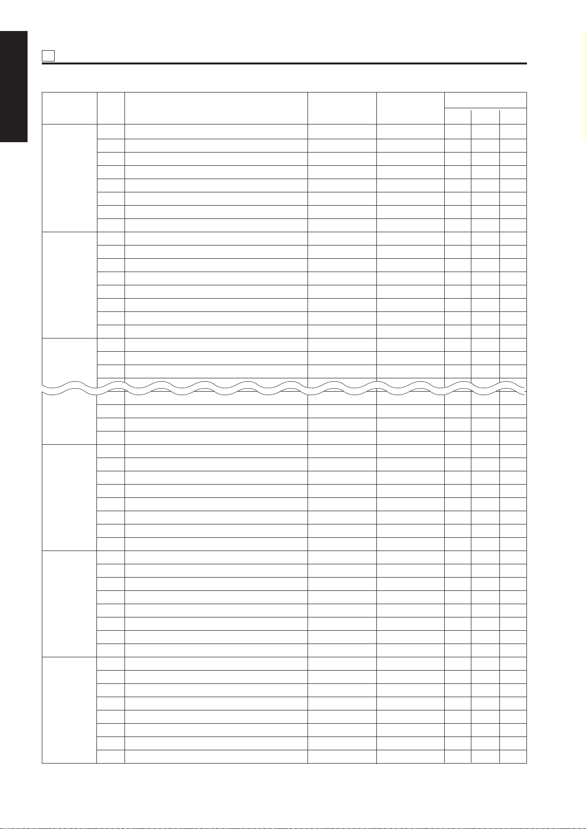
< List of Software Switches >
1 ADJUSTMENT
DIPSW No. Bit Function 0 1
0 Condition for stopping copying after * 1 * 1 1 1 1
indication of toner supply
1 Ditto * 1 * 1 0 0 0
2 Method for stopping copying after * 2 * 2
indication of toner supply 1 1 1
DIPSW 1
3 Ditto * 2 * 2 0 0 0
4 Inhibition of copying when PM count is Inhibited Not inhibited 0 0 0
reached
5 Number of copies made before inhibition * 3 * 3 0 0 0
of copying
6 Ditto * 3 * 3 0 0 0
7 Ditto * 3 * 3 0 0 0
0– – – – – –
1 Electrode cleaning cycle (before starting * 4 * 4 0 0 0
work every morning)
2 Ditto * 4 * 4 0 0 0
DIPSW 2
3 Ditto * 4 * 4 0 0 0
4 Electrode cleaning cycle (after printout) * 5 * 5 0 0 0
5 Ditto * 5 * 5 0 0 0
6 Blade replacement count * 6 * 6 0 0 0
7 Ditto * 6 * 6 0 0 0
0– – – – – –
1 SC latch Latched Unlatched 0 0 0
2 25, 36, 47 mode password request Not requested Requested 0 0 0
(password: 9272)
DIPSW 3
3 Charging corona unit cleaning function ON Off 0 0 0
4
Transfer /separation
corona unit
cleaning
ON Off 0 0 0
function
5 Blade replacement request Not requested Requested 0 0 0
6 47 mode 15-01 data collection clearing Disabled Enabled 0 0 0
7– – –
0 ADF skewed image correction enabled/ Enabled Disabled 0 0 0
disabled
1 Inhibition of post card/thick paper/double Disabled Enabled 0 0 0
side
DIPSW 4
2 Destination selection * 7 * 7 0 1 0
3 Ditto * 7 * 7 0 0 1
4– – – – – –
5
Inhibition of magnified APS (Japan/Europe)
Enabled Disabled 0 1 0
6 Fixed magnification rate setting change Enabled Disabled 1 0 0
7 A3 (11 x 17) counting method
Incremented by 1 Incremented by 2
Initial V alue
North
Japan
America
Europe
000
1 - 8
Page 10

25
ADJUSTMENT
DIPSW No. Bit Function 0 1
0 Toner concentration threshold * 8 * 8 0 0 0
1 Ditto * 8 * 8 0 0 0
2– – – – – –
DIPSW 5
3– – – – – –
4 2 dot PWM table in photo mode * 9 * 9 0 0 0
5 Ditto * 9 * 9 1 1 1
6– – – – – –
7– – – – – –
0 Transfer/separation corona unit output * 10 * 10 0 0 0
for plain paper
1 Ditto * 10 * 10 0 0 0
2 Ditto * 10 * 10 0 0 0
3 Transfer/separation corona unit output * 11 * 11 0 0 0
DIPSW 6
for thick paper
4 Ditto * 11 * 11 0 0 0
5 Transfer/separation corona unit output * 12 * 12 0 0 0
for thin paper
6 Ditto * 12 * 12 0 0 0
7 Potential control (Note 1) Performed Not performed 0 0 0
0– – – – – –
1– – – – – –
2– – – – – –
3– – – – – –
DIPSW 7
4– – – – – –
5 Transfer/separation corona unit output * 13 * 13 0 0 0
for recycled paper
6 Ditto * 13 * 13 0 0 0
7 Ditto * 13 * 13 0 0 0
0 Fixing temperature setting switchov er * 14 * 14 0 0 0
1 Ditto * 14 * 14 0 0 0
2 Fixing upper roller initial rotation * 15 * 15 0 0 1
DIPSW 8
3 Ditto * 15 * 15 0 0 0
4 Fixing upper roller initial rotation time * 16 * 16 0 0 0
5 Ditto * 16 * 16 0 0 0
6 A3(11x17) PM counter switch 1 count 2 count 0 0 0
7– – – – – –
0– – – – – –
1– – – – – –
2 Copy card message * 17 * 17 0 0 0
DIPSW 9
3 Ditto * 17 * 17 0 0 0
4 Copy count limit * 18 * 18 0 0 0
5 Ditto * 18 * 18 0 0 0
6 Ditto * 18 * 18 0 0 0
7 Ditto * 18 * 18 0 0 0
Initial V alue
North
Japan
America
Europe
1 ADJUSTMENT
1 - 9
Page 11

25 ADJUSTMENT
DIPSW No. Bit Function 0 1
1 ADJUSTMENT
0– – – – – –
1– – – – – –
2– – – – – –
DIPSW 10
3– – – – – –
4– – – – – –
5– – – – – –
6– – – – – –
7– – – – – –
0 SC detection Detected Not detected 0 0 0
1 Post card bypass feed (Note 2) Enabled Disabled 0 0 0
2– – – – – –
3 SC/E code screen switchover Switched Not switched 0 0 0
DIPSW 11
4 Selection of filter for jagged edges on Not selected Selected 0 0 0
slanting lines
5 Image quality mode selection * 19 * 19 0 0 0
6 Ditto * 19 * 19 0 0 0
7 Jam indication screen type Without jam
code
0 Black band print interval
Every 10 copies Every 50 copies
1– – – – – –
2 Operating jam detection Detected Not detected 0 0 0
DIPSW 12
3 Printer centering adjustment Adjusted Not adjusted 0 0 0
4 HV manual adjustment output Output Not output 0 0 0
5– – – – – –
6– – – – – –
7γ selection γ conversion γ conversion 0 0 0
made not made
0 Size detection 1 A5 5.5 x 8.5 0 1 0
1 Size detection 2 A4R 8.5 x 11R 0 1 0
2 Size detection 3 8.5 x 14 F4 0 0 1
DIPSW 13
3 Size detection 4 * 20 * 20 0 0 0
4 Ditto * 20 * 20 0 1 0
5 F4 size detection * 21 * 21 0 0 0
6 Ditto * 21 * 21 0 0 0
7– – – – – –
With jam code
Initial V alue
North
Japan
America
Europe
000
000
1 - 10
Page 12
25
ADJUSTMENT
DIPSW No. Bit Function 0 1
0 Size detection 5 (main unit) B4 · 11 x 17/ 8K/16K 0 0 0
B5 · 8.5 x 11
1– – – – – –
2– – – – – –
3 Size detection 5 (bypass feed) B4 · 11 x 17/ 8K/16K 0 0 0
DIPSW 14
B5 · 8.5 x 11
4 Size detection 5 (platen) B4 · 11 x 17/ 8K/16K 0 0 0
B5 · 8.5 x 11
5 Size detection 5 (ADF) B4 · 11 x 17/ 8K/16K 0 0 0
B5 · 8.5 x 11
6– – – – – –
7– – – – – –
0– – –
1
Maximum number of sheets that can be stapled
* 22 * 22 – – –
2 Ditto * 22 * 22 0 0 0
3 FNS alarm stop SW * 23 * 23 0 0 0
DIPSW 15
4 Ditto * 23 * 23 0 0 0
5 KRDS modem connection recognition Disconnect Connect 0 0 0
6 Dmax. value in printer mode 1.35 1.42 0 0 0
7 PWM selection for 1-bit ED 230 255 0 0 0
0 Non-image area automatic erasure Rectangular Tilted erasure 1 0 0
method erasure
1 Dual inhibition Reservation Reservation 0 0 0
enabled disabled
2– – – – – –
DIPSW 16
3 C(K) counting in printer mode Counted Not counted
4 TC start date indication Indicated Not indicated
5 Non-original area automatic erasure * 24 * 24 0 0 0
mode judgement level
6 Ditto * 24 * 24 0 0 0
7 Ditto * 24 * 24 0 0 0
0 WT summer time setting * 25 * 25 0 0 0
1 Ditto * 25 * 25 1 1 1
2 Ditto * 25 * 25 1 1 1
DIPSW 17
3 Ditto * 25 * 25 0 0 0
4– – – – – –
5– – – – – –
6– – – – – –
7– – – – – –
0 Tray 1's faulty part isolation Normal Unavailable 0 0 0
1 Tray 2's faulty part isolation Normal Unavailable 0 0 0
2 Tray 3's faulty part isolation Normal Unavailable 0 0 0
DIPSW 18
3 Tray 4's (LCT's) faulty part isolation Normal Unavailable 0 0 0
4 ADF faulty part isolation Normal Unavailable 0 0 0
5 Folding, stapling and folding faulty part
isolation Normal Unavailable 0 0 0
6 CF faulty part isolation Normal Unavailable 0 0 0
7– – – – – –
Initial V alue
North
Japan
America
Europe
1 ADJUSTMENT
1 - 11
Page 13
25 ADJUSTMENT
DIPSW No. Bit Function 0 1
1 ADJUSTMENT
0– – – – – –
1– – – – – –
2– – – – – –
DIPSW 19
3– – – – – –
4– – – – – –
5– – – – – –
6– – – – – –
7– – – – – –
0 Group stapling Enabled Disabled 0 0 0
1– – – – – –
2– – – – – –
DIPSW 20
3– – – – – –
4– – – – – –
5– – – – – –
6– – – – – –
7– – – – – –
0– – – – – –
1– – – – – –
DIPSW 21
2– – – – – –
3– – – – – –
4– – – – – –
DIPSW 27
5– – – – – –
6– – – – – –
7– – – – – –
0– – – – – –
1– – – – – –
2– – – – – –
DIPSW 28
3– – – – – –
4– – – – – –
5– – – – – –
6– – – – – –
7– – – – – –
0– – – – – –
1– – – – – –
2– – – – – –
DIPSW 29
3– – – – – –
4– – – – – –
5– – – – – –
6– – – – – –
7– – –
0– – – – – –
1 25 mode collection data for 5-11 verification
Display restriction No display restriction
2– – – – – –
DIPSW 30
3– – – – – –
4– – – – – –
5– – – – – –
6– – – – – –
7– – – – – –
Initial V alue
North
Japan
America
Europe
000
1 - 12
Page 14

25
ADJUSTMENT
Note 1: Bit 7 of DIP SW6 (potential control performed/not performed) is set to determine whether potential
control is to be performed using the drum potential sensor. This setting is used to check whether
the image quality has been deteriorated due to a faulty drum potential sensor.
Note 2: When feeding a postcard from the bypass paper feed tray, release timing of the paper feed roller
can be delayed to improve the paper feed capability.
1 ADJUSTMENT
1 - 13
Page 15
25 ADJUSTMENT
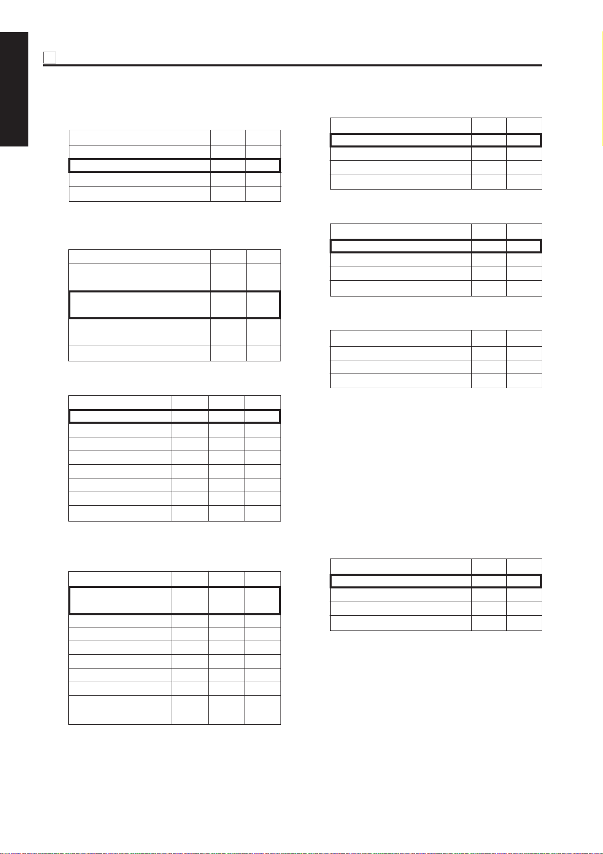
* 1 Condition for stopping copying after indication of
1 ADJUSTMENT
toner supply request
Mode 1-1 1-0
Stops after printing 1500 copies
Stops after printing 3000 copies
Stops after printing 4000 copies
Stops after printing 5000 copies
* 2 Method for stopping copying after indication of
toner supply request
Mode
Stops after ejecting the paper
remaining in the machine
Stops after printing specified
number of copies
Stops at the end of the current
job
Does not stop
* 3
Number of copies made before inhibition of copying
00
01
10
11
1-3 1-2
00
01
10
11
* 5 Electrode cleaning cycle (after printout)
Mode 2-5 2-4
Count 20,000 0 0
Count 30,000 0 1
Count 40,000 1 0
Count 50,000 1 1
* 6 Blade replacement count
Mode 2-7 2-6
Count 250,000 0 0
Count 300,000 0 1
Count 350,000 1 0
Count 400,000 1 1
* 7 Destination switchover
Mode 4-3 4-2
Japan 0 0
USA 0 1
Europe 1 0
Mode 1-7 1-6 1-5
1,000 copies 0 0 0
2,000 copies 0 0 1
3,000 copies 0 1 0
4,000 copies 0 1 1
5,000 copies 1 0 0
1,000 copies 1 0 1
1,000 copies 1 1 0
1,000 copies 1 1 1
* 4 Electrode cleaning cycle (before work every
morning)
Mode 2-3 2-2 2-1
Clean work every 0 0 0
morning
Count 5,000 0 0 1
Count 10,000 0 1 0
Count 15,000 0 1 1
Count 20,000 1 0 0
Count 25,000 1 0 1
Count 30,000 1 1 0
Need not clean every 1 1 1
morning
* 8 Toner concentration threshold
This bit sets the read level of the toner
concentration patch formed on the drum to
determine the toner concentration. The setting
can be made by shifting the threshold of black
color to the positive or negative side.
• Standard –3: The image becomes darker.
• Standard +3: The image becomes lighter.
• Standard +5: The image becomes far
lighter.
Mode 5-1 5-0
Standard 0 0
Standard –3 0 1
Standard +3 1 0
Standard +5 1 1
1 - 14
Page 16

25
ADJUSTMENT
* 9 2 dot PWM table in photo mode
Mode 5-5 5-4
1 dot PWM 0 0
Table 1 0 1
Table 2 1 0
Table 3 1 1
* 10 Transfer/separation corona unit output for plain
paper
Mode 6-2 6-1 6-0
Not specified 0 0 0
55 kg plain paper (Japan) 001
20 lb plain paper (USA) 010
80 g plain paper (Europe) 011
Recycled paper 1 (Japan) 100
Recycled paper 2 (USA) 101
Recycled paper 3 (Europe) 110
Special paper 1 1 1
* 11 Transfer/separation corona unit output for thick
paper
Mode 6-4 6-3
No specification 0 0
200 g paper 0 1
170 g paper 1 0
Postcard 1 1
* 12 Transfer/separation corona unit output for thin
paper
* 13Transfer/separation corona unit output for recy-
cled paper
1 ADJUSTMENT
Mode 7-7 7-6 7-5
000
55 kg plain paper (Japan) 001
20 lb plain paper (USA) 010
80 g plain paper (Europe) 011
Recycled paper 1 (Japan) 100
Recycled paper 2 (USA) 101
Recycled paper 3 (Europe) 110
Special paper 1 1 1
* 14Fixing temperature setting switchover
This bit is used to change the fixing temperature
when fixing is insufficient or paper is curled
largely. This setting is eff ectiv e only f or plain paper. It is not reflected in thick paper, thin paper,
and preheat temperature.
• Standard: Standard setting
• Standard +5°C: Select this setting when
fusion is insufficient.
• Standard –5°C: Select this setting when
paper is curled largely.
• Standard–10°C: Select this setting when
paper is curled far largely.
Mode 8-1 8-0
Standard 0 0
Standard +5°C 0 1
Standard –5°C 1 0
Standard –10°C 1 1
Mode 6-6 6-5
No specification 0 0
45 g paper 0 1
48 g paper 1 0
16 lb/80 g paper 1 1
1 - 15
Page 17

25 ADJUSTMENT
* 15Fixing upper roller initial rotation
1 ADJUSTMENT
Fixing may be insufficient in the morning if the
temperature of the place where the machine is
installed is low. To prevent this, increase the
warm-up time (fixing upper roller initial rotation
time) to allow the fixing lower roller to be warmed
up to the normal temperature. This bit specifies
the condition(s) under which initial rotation of the
fixing upper roller is required.
• Low temperature: Initial rotation of the fixing
upper roller is carried out only under the low
temperature condition.
• Low and normal temperatures: Initial rotation
of the fixing upper roller is carried out under
low and normal temperature conditions.
• Low, normal, and high temperatures: Initial
rotation of the fixing upper roller is carried out
under low , normal, and high temperature conditions.
Destination Mode 8-3 8-2
Japan/US Low temperature 0 0
Europe Low and normal 1 0
temperature
Low, normal, and high
temperatures
* 16 Fixing upper roller initial rotation time
This bit sets the maximum time of initial rotation
of the fixing upper roller. When 0 second is specified, initial rotation of the fixing upper roller is
not carried out.
Mode 8-5 8-4
180 seconds 0 0
300 seconds 0 1
60 seconds 1 0
0 second 1 1
11
* 18Copy count limit
Mode 9-7 9-6 9-5 9-4
No limit 0 0 0 0
1 copy 0 0 0 1
3 copies 0 0 1 0
5 copies 0 0 1 1
9 copies 0 1 0 1
10 copies 0 1 0 1
20 copies 0 1 1 0
30 copies 0 1 1 1
50 copies 1 0 0 0
99 copies 1 0 0 1
No limit 1 0 1 0
No limit 1 0 1 1
No limit 1 1 0 0
No limit 1 1 0 1
No limit 1 1 1 0
No limit 1 1 1 1
* 19Image quality mode
Mode 11-6 11-5
Normal: 1ED; Fine: 2ED 0 0
Normal: 1ED; Fine: 4ED 0 1
Normal: 2ED; Fine: 4ED 1 0
–11
* 20Size detection 4
Destination Mode 13-4 13-3
Japan/Europe A5R 0 0
B6R 0 1
USA 5.5 x 8.5R 1 0
* 21F4 size detection
*17 Copy card message
Mode 9-3 9-2
Insert copy card. 0 1
Insert coins. 1 0
Mode 13-6 13-5
8 x 13 0 0
8.25 x 13 0 1
8.125 x 13.25 1 0
8 x 13 1 1
1 - 16
Page 18
25
ADJUSTMENT
* 22 Maximum number of sheets that can be stapled
Mode 15-2 15-1
50 sheets 0 0
45 sheets 0 1
40 sheets 1 0
35 sheets 1 1
* 23 FNS alarm stop SW
Mode 15-4 15-3
Stop immediately after detection 0 0
Stop at end of copy after 0 1
detection
No alarm stop 1 0
No alarm stop 1 1
* 24 Selection of area to be erased in non-original area
automatic erasure
This bit is used to make a setting associated with
the non-original automatic erasure mode (application function).
1. Selection of the area to erase
There are two methods for selecting the area to
be erased, “rectangular erasure” and “ tilted
erasure.” Select the desired method.
· Tilted erasure: The original is not rectangular
(e.g., circular original).
· Rectangular erasure: The original is rectangular
(e.g., original of a standard size).
If a rectangular original is placed in a tilted position, black stripes may appear in the “rectangular erasure” mode. If there is a b lack area on the
periphery of the original, this area may be judged
as being outside the original, resulting in improper erasure of the area outside the original.
In such a case, the “rectangular erasure” mode
is selected automatically.
2. Selection of identification level
When the original is dark or external light (from
the fluorescent lamp or sun) enters the machine,
it becomes sometimes difficult to discriminate
between the area inside the original and the area
outside it. In such a case, the original area identification level can be changed.
Remarks:
In the key operator mode, you can use the
memory switch that has a non-original area automatic erasure function. This memory switch
allows you to select the area to be copied when
copy paper is selected manually.
• To copy only image size area determined by
the APS sensor, select “Erase the area outside
the original.”
• To copy the entire area of the original to the
selected paper, select “Do not erase the area
outside the original.”
Note:
The APS sensor is effective if copy paper is selected manually.
Mode
Standard
Dark original
Darker original
Interference light
Uneven stripes
Standard
Dark original
Darker original
Interference light
Uneven stripes
* For rectangular original density (dark original
/darker original)
Use this mode to set the density level
threshhold value to the dark when copying a
news article on a newspaper.
(This mode is for copying a ne wspaper whose
texture color is dark. Margin for interference
light decreases.)
* As a prev entive measure to cope with the non-
standard original density(appearance of
uneven stripes)
Use this mode to suppress uneven stripes
appearing on a copied paper when copying a
newspaper whose texture color is dark.
(Margin for interference light decreases.)
* Threshold for coping with interference light
Use this mode to increase the probability of
copier to operate normal, when it is hard to
prevent interference light penetrating to scan
area, and when copying comparatively low
density (bright texture color) original.
Area
Standard original
Standard original
Standard original
Standard original
Standard original
Non-standard
original
Non-standard
original
Non-standard
original
Non-standard
original
Non-standard
original
16-7 16-6 16-5 16-0
0000
0010
0100
0110
1000
0001
0011
0101
0111
1001
1 ADJUSTMENT
1 - 17
Page 19
25 ADJUSTMENT
* 25WT summer time setting
1 ADJUSTMENT
Mode 17-3 17-2 17-1 17-0
0 minute 0 0 0 0
10 minutes 0 0 0 1
20 minutes 0 0 1 0
30 minutes 0 0 1 1
40 minutes 0 1 0 0
50 minutes 0 1 0 1
60 minutes 0 1 1 0
70 minutes 0 1 1 1
80 minutes 1 0 0 0
90 minutes 1 0 0 1
100 minutes 1 0 1 0
110 minutes 1 0 1 1
120 minutes 1 1 0 0
130 minutes 1 1 0 1
140 minutes 1 1 1 0
150 minutes 1 1 1 1
[3] Setting the Tray Size
This function stores the tray size in the memory of the
main unit when it has been changed by the servicepersonnel. This function is effectiv e when the machine
is equipped with an optional LCT.
Select a tray size among standard, non-standard paper
sizes. After selecting a tr a y siz e , specify a paper size .
1. Setting the standard size
Step Operation
1 Enter the 25 mode.
2 [25 Mode Menu Screen]
Select “ 2 Tray Size Setting.”
3 [Tray Size Setting Screen]
Press the
STANDARD SIZE
4 [Tray Size Selection Screen]
Press the or button to select a
paper size.
5 Press the
OK
button to finish setting.
To cancel the new setting, press the
CANCEL
button.
Pressing either button will display the 25
Mode Menu screen again.
button.
1 - 18
Page 20

25
ADJUSTMENT
2. Setting the non-standard size
Step Operation
1 Enter the 25 mode.
2 [25 Mode Menu Screen]
Select “ 2 Tray Size Setting.”
3 [Tray Size Setting Screen]
Press the
4 [Tray Size Selection Screen]
Press the key for specifying the main
(vertical) scanning direction to display it
in reverse video.
5 Press the or button or numeric
keys to enter the size in the main
(vertical)scanning direction.
6 Press the button for specifying the sub
(horizontal) scanning direction to display
it in reverse video.
7 Press the or button or numeric
keys to enter the size in the sub (horizontal) scanning direction.
8 Press the
To cancel the new setting, press the
CANCEL
Pressing either button will display the 25
Mode Menu screen again.
Reference 1:
Each time the current tray size is changed on
this screen, the new setting will be written into
the non-volatile memory.
Reference 2:
Standard sizes that can be set for the LCT are
as follows: A4, B5, 8.5 x 11
Caution:
Sizes of tray 1 (upper tray), tray 2 (middle tray),
tray 3 (lower tray), and by-pass tray are not set
using the non-volatile memory.
For trays 1, 2, and 3, their guide plate positions
are read by sensors. For the by-pass tray, its
paper setting position and guide plate position
are read by sensors.
NON-STANDARD SIZE
OK
button to finish setting.
button.
button.
[4] PM Count Resetting
Care should be taken not to reset the PM count by
mistake.
Step Operation
1 Enter the 25 mode.
2 [25 Mode Menu Screen]
Select “ 3 PM count.”
3 [PM Count/Cycle Setting Screen]
Press the
RESET COUNT
button.
4 [Reset Confirmation Screen]
Press the
YES
button.
The PM count is reset and the start date
is input automatically.
Pressing the NO button closes the
Reset Confirmation screen at once.
5 Press the
OK
button to finish setting.
To cancel the new setting, press the
CANCEL
button.
Pressing either button will display the 25
Mode Menu screen again.
[5] Setting the PM Cycle
This function allows you to change the PM cycle.
Caution: The PM cycle is factory-set. Use this
function to change the factory-set PM
cycle.
Step Operation
1 Enter the 25 mode.
2 [25 Mode Menu Screen]
Select “ 3 PM count.”
3 [PM Count/Cycle Setting Screen]
Press the
4 After making sure that three digits of the
cycle value are displayed in reverse
video, enter a desired cycle value using
numeric keys.
Only the three digits of the cycle value
can be entered. The entered digits will
be shifted to the left one after another.
5 Press the
To cancel the new setting, press the
CANCEL
Pressing either button will display the 25
Mode Menu screen again.
PM CYCLE SET
OK
button to finish setting.
button.
button.
1 ADJUSTMENT
1 - 19
Page 21

25 ADJUSTMENT
[6] Collecting Data
This function allows you to view various data retained
1 ADJUSTMENT
by the machine.
Reference: The above data can also be viewed
using the data collection function of
the KRDS.
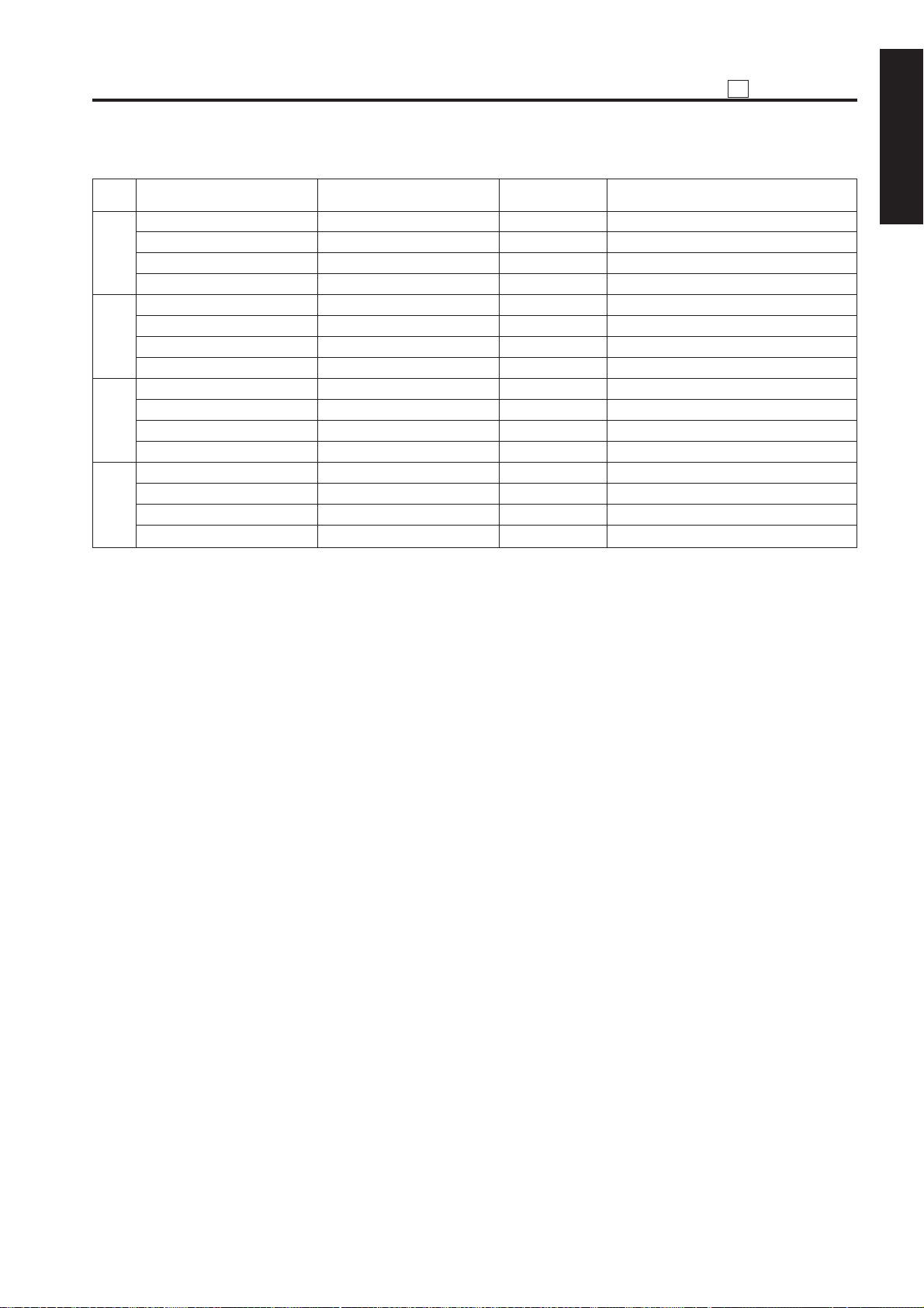
1. Data that can be Viewed
No. Data T ype
1
Total count by paper size
2
Copy count by paper size
3
Print count by paper size
4 ADF paper passage
count
5 Time series jam data
6 Jam occurrence count
7 Count by copy mode
8 SC occurrence count
9 Paper conveyance time
data
10 Local jam occurrence
count
11 Local SC occurrence
count
Note : When bit 1 of DIP switch 30 is set to 0,
only collected data 1 to collected data
4 can be viewed.
2. Viewing Collected Data 1 to Collected
Data 4
Step Operation
1 Enter the 25 mode.
2 [25 Mode Menu Screen]
Select “ 4 Data Collection.”
3 Select the collected data you want to
view by pressing one of numeric keys
1
to 4 .
4 [Individual Data View Screen]
View the selected data by scrolling the
screen using and keys.
5 Press the
return to the 25 Mode Menu screen.
PREVIOUS SCREEN
Preparation
Enter the 25
mode, select
“1 Software
DIP SW
Setting,” and
set bit 1 of DIP
switch 30 to 1.
(Note 1)
button to
3. Viewing Collected Data 5 to Collected
Data 11
Step Operation
1 Enter the 25 mode.
2 [25 Mode Menu Screen]
Select “ 1 Software DIP SW Setting.”
3 [Software DIP SW Setting Screen]
Set bit 1 of DIP switch 30 to 1.
4 Press the
PREVIOUS SCREEN
return to the 25 Mode Menu screen.
5 [25 Mode Menu Screen]
Select “ 4 Data Collection.”
6 [Collected Data Selection Screen]
Select the collected data you want to
view by pressing one of numeric keys
5
to 11.
To select key 11 press the key.
If the key is pressed with key 11displayed, the Collected Data Selection
screen containing keys 1 to 10 appears
again.
7 [Individual Data View Screen]
View the selected data by scrolling the
screen using and keys. (Note 1)
8 Press the
PREVIOUS SCREEN
return to the 25 Mode Menu screen.
Note : On the Individual Data View screen
showing the local jam occurrence count
(collected data 10 ) or local SC occur-
rence count (collected data 11 ), the
COUNT RESET
Pressing the
button appears.
COUNT RESET
sets the selected data count.
button to
button to
button re-
1 - 20
Page 22

4. Details on Display Data
(1) Total count by paper size
25
ADJUSTMENT
1 ADJUSTMENT
KRDS parameter
NO
10 09 Special Special Special 99999999
1. Each time a printed copy is ejected, the counter is incremented by 1 regardless of the paper size.
2. If the size of the paper used is none of the paper sizes 1-9 listed above, the counter is incremented in
(B1, B6, B8)
1 00 A2 17x22 A2 99999999 All counters are
2 01 A3 11x17 A3 99999999
3 02 B4 8.5x14 B4 99999999
4 03 A4 8.5x11 A4 99999999
5 04 B5 5.5x8.5 B5 99999999
6 05 A5 — A5 99999999
7 06 B6 — F4 99999999
8 07 8.5x14 — — 99999999
9 08 8.5x11 A4 — 99999999
aspecialmanner (SEF and LEF are counted assuming that they are of the same size.)
Japan U.S.A. Europe
Destination
Maximum count Remarks
8-digit counters.
1 - 21
Page 23

25 ADJUSTMENT
(2) Copy count by fixed part
1 ADJUSTMENT
KRDS
para-
NO
meter
(Z1)
1 00 Fixing unit cleaning web 55VA-524 99999999 Count 1 per ejected paper for single sided, 2 for
2 01 Developer 55VA3060 99999999 Always unaffected by 25DIPSW
3 02 Photosensitive drum 55VA-240 99999999 Always unaffected by 25DIPSW
4 03 Cleaning blade 55VA5601 99999999 25DIPSW8-6
5 04 Fur brush 55VA-574 99999999 25DIPSW8-6
6 05 Charging grid 55VA2508 99999999 25DIPSW8-6
7 06 Charging corona unit cleaning 55VA-255 99999999 25DIPSW8-6
8 07 Suction filter 55VA3108 99999999 25DIPSW8-6
9 08 Separation claw 55VA2919 99999999 25DIPSW8-6
10 09 Transfer/separation wires 55VA2613 99999999 25DIPSW8-6
Part name Part No.
Maximum
count
Counting condition
double sided
For A3, 11x17, count 2 per ejected paper for single
sided, 4 for double sided
For A3, 11x17, count 2 per ejected paper for single
sided, 4 for double sided
=0: Count 1 per ejected paper for single sided, 2
for double sided
=1: For A3, 11x17, count 2 per ejected paper for
single sided, 4 for double sided
=0: Count 1 per ejected paper for single sided, 2
for double sided
=1: For A3, 11x17, count 2 per ejected paper for
single sided, 4 for double sided
=0: Count 1 per ejected paper for single sided, 2
for double sided
=1: For A3, 11x17, count 2 per ejected paper for
single sided, 4 for double sided
=0: Count 1 per ejected paper for single sided, 2
for double sided
=1: For A3, 11x17, count 2 per ejected paper for
single sided, 4 for double sided
=0: Count 1 per ejected paper for single sided, 2
for double sided
=1: For A3, 11x17, count 2 per ejected paper for
single sided, 4 for double sided
=0: Count 1 per ejected paper for single sided, 2
for double sided
=1: For A3, 11x17, count 2 per ejected paper for
single sided, 4 for double sided
=0: Count 1 per ejected paper for single sided, 2
for double sided
=1: For A3, 11x17, count 2 per ejected paper for
single sided, 4 for double sided
1 - 22
Page 24

25
ADJUSTMENT
KRDS
para-
NO
meter
(Z1)
11 0A Transfer/separation corona unit 55VA-276 99999999 25DIPSW8-6
12 0B Fixing upper roller 55VA5304 99999999 25DIPSW8-6
13 0C Fixing lower roller assembly 55VA-528 99999999 25DIPSW8-6
14 0D Fixing upper claw 55VA5321 99999999 25DIPSW8-6
15 0E Fixing lower claw 26AA5329 99999999 25DIPSW8-6
16 0F Insulating sleeve 45405339 99999999 25DIPSW8-6
17 10 Upper roller bearing 45407504 99999999 25DIPSW8-6
18 11 Cleaning roller 55VA5386 99999999 25DIPSW8-6
19 12 Drum temperature sensor 55VA-209 99999999 25DIPSW8-6
Part name Part No.
Maximum
count
=0: Count 1 per ejected paper for single sided, 2
for double sided
=1: For A3, 11x17, count 2 per ejected paper for
single sided, 4 for double sided
=0: Count 1 per ejected paper for single sided, 2
for double sided
=1: For A3, 11x17, count 2 per ejected paper for
single sided, 4 for double sided
=0: Count 1 per ejected paper for single sided, 2
for double sided
=1: For A3, 11x17, count 2 per ejected paper for
single sided, 4 for double sided
=0: Count 1 per ejected paper for single sided, 2
for double sided
=1: For A3, 11x17, count 2 per ejected paper for
single sided, 4 for double sided
=0: Count 1 per ejected paper for single sided, 2
for double sided
=1: For A3, 11x17, count 2 per ejected paper for
single sided, 4 for double sided
=0: Count 1 per ejected paper for single sided, 2
for double sided
=1: For A3, 11x17, count 2 per ejected paper for
single sided, 4 for double sided
=0: Count 1 per ejected paper for single sided, 2
for double sided
=1: For A3, 11x17, count 2 per ejected paper for
single sided, 4 for double sided
=0: Count 1 per ejected paper for single sided, 2
for double sided
=1: For A3, 11x17, count 2 per ejected paper for
single sided, 4 for double sided
=0: Count 1 per ejected paper for single sided, 2
for double sided
=1: For A3, 11x17, count 2 per ejected paper for
single sided, 4 for double sided
Counting condition
1 ADJUSTMENT
1 - 23
Page 25

25 ADJUSTMENT
KRDS
para-
NO
1 ADJUSTMENT
(Z1)
20 13 Transfer/separation corona unit 55VA-270 99999999 25DIPSW8-6
21 14 Insulation sleeve (heating) 26AA5315 99999999 25DIPSW8-6
22 15 Heating roller bearing 26AA5316 99999999 25DIPSW8-6
23 16
24 17
25 18 Fixing unit heating roller 55VA5307 99999999 25DIPSW8-6
26 19 Ozone filter 55FA7301 99999999 25DIPSW8-6
27 1A Charging corona unit 55VA-250 99999999 25DIPSW8-6
28 1B PCL 55VA8307 99999999 25DIPSW8-6
Upper roller error detection sensor
Heating roller error detection sensor
Part name Part No.
55VA8804 99999999 25DIPSW8-6
55VA8806 99999999 25DIPSW8-6
Maximum
countmeter
Counting condition
=0: Count 1 per ejected paper for single sided, 2
for double sided
=1: For A3, 11x17, count 2 per ejected paper for
single sided, 4 for double sided
=0: Count 1 per ejected paper for single sided, 2
for double sided
=1: For A3, 11x17, count 2 per ejected paper for
single sided, 4 for double sided
=0: Count 1 per ejected paper for single sided, 2
for double sided
=1: For A3, 11x17, count 2 per ejected paper for
single sided, 4 for double sided
=0: Count 1 per ejected paper for single sided, 2
for double sided
=1: For A3, 11x17, count 2 per ejected paper for
single sided, 4 for double sided
=0: Count 1 per ejected paper for single sided, 2
for double sided
=1: For A3, 11x17, count 2 per ejected paper for
single sided, 4 for double sided
=0: Count 1 per ejected paper for single sided, 2
for double sided
=1: For A3, 11x17, count 2 per ejected paper for
single sided, 4 for double sided
=0: Count 1 per ejected paper for single sided, 2
for double sided
=1: For A3, 11x17, count 2 per ejected paper for
single sided, 4 for double sided
=0: Count 1 per ejected paper for single sided, 2
for double sided
=1: For A3, 11x17, count 2 per ejected paper for
single sided, 4 for double sided
=0: Count 1 per ejected paper for single sided, 2
for double sided
=1: For A3, 11x17, count 2 per ejected paper for
single sided, 4 for double sided
1 - 24
Page 26

25
ADJUSTMENT
KRDS
para-
NO
meter
(Z1)
29 1C Developer 55VA-300 99999999 25DIPSW8-6
30 1D TSL 55VA8308 99999999 25DIPSW8-6
31 1E Tray 1 paper feed roller 55VA-464 99999999 1 is counted each time the paper from tray 1 is
32 1F
33 20 Tray 1 paper feed clutch 55VA8201 99999999 1 is counted each time the paper from tray 1 is
34 21 Tray 1 conveyance clutch 55VA8201 99999999 1 is counted each time the paper from tray 1 is
35 22 Tray 1 paper passage count 55VA-400 99999999 1 is counted each time the paper from tray 1 is
36 23 Tray 2 paper feed roller 55VA-464 99999999 1 is counted each time the paper from tray 2 is
37 24 Tray 2 conveyance roller/ 55VA-463 99999999 1 is counted each time the paper from tray 2 is
38 25 Tray 2 paper pickup clutch 55VA8201 99999999 1 is counted each time the paper from tray 2 is
39 26 Tray 2 conveyance clutch 55VA8201 99999999 1 is counted each time the paper from tray 2 is
40 27 Tray 2 paper passage count 55VA-401 99999999 1 is counted each time the paper from tray 2 is
41 28 Tray 3 feed roller 55VA-484 99999999 1 is counted each time the paper from tray 3 is
42 29 Tray 3 conveyance roller/ 55VA-483 99999999 1 is counted each time the paper from tray 3 is
43 2A Tray 3 paper pickup clutch 55VA8201 99999999 1 is counted each time the paper from tray 3 is
44 2B Tray 3 conveyance clutch 55VA8201 99999999 1 is counted each time the paper from tray 3 is
45 2C Tray 3 paper passage count 55VA-410 99999999 1 is counted each time the paper from tray 3 is
46 2D By-pass tray paper feed roller 55VA-464 99999999 1 is counted each time the paper from bypass tray
47 2E By-pass tray conveyance roller/ 55VA-463 99999999 1 is counted each time the paper from bypass tray
48 2F By-pass tray paper passage 55VA-500 99999999 1 is counted each time the paper from bypass tray
Tray 1 conveyance roller/reversal roller
reversal roller ejected.
reversal roller ejected.
reversal roller is ejected.
count is ejected.
Part name Part No.
55VA-463 99999999 1 is counted each time the paper from tray 1 is
Maximum
count
Counting condition
=0: Count 1 per ejected paper for single sided, 2
for double sided
=1: For A3, 11x17, count 2 per ejected paper for
single sided, 4 for double sided
=0: Count 1 per ejected paper for single sided, 2
for double sided
=1: For A3, 11x17, count 2 per ejected paper for
single sided, 4 for double sided
ejected.
ejected.
ejected.
ejected.
ejected.
ejected.
ejected.
ejected.
ejected.
ejected.
ejected.
ejected.
ejected.
is ejected.
1 ADJUSTMENT
1 - 25
Page 27

25 ADJUSTMENT
KRDS
para-
NO
1 ADJUSTMENT
meter
(Z1)
49 30 LCT feed roller 55VA-484 99999999 1 is counted each time the paper from LCT is
50 31 LCT conveyance roller/reversal 55VA-483 99999999 1 is counted each time the paper from LCT is
roller ejected.
51 32 LCT paper feed clutch 55VA8201 99999999 1 is counted each time the paper from LCT is
52 33 LCT conveyance clutch 55VA8201 99999999 1 is counted each time the paper from LCT is
53 34 LCT paper passage count 13GG-050 99999999 1 is counted each time the paper from LCT is
54 35 Conveyance roller at vertical 55VA4410 99999999 1 is counted each time the paper from tray 1/2/3 is
conveyance exit ejected.
55 36 Conveyance roller (middle) of 55VA4411 99999999 1 is counted each time the paper from tray 2/3 is
vertical conveyance unit ejected.
56 37 Conveyance roller (lower) of 55VA4411 99999999 1 is counted each time the paper from tray 3 is
vertical paper conveyance unit ejected.
57 38 Conveyance clutch of vertical 55VA-8202 99999999 1 is counted each time the paper from tray 2/3 is
paper conveyance unit ejected.
58 39 FNS up/down motor 129U8004 99999999 1 is counted each time the paper from FNS main
59 3A FNS stapler (front) 129U4266 99999999 1 is counted each time a copy is ejected in SS front
60 3B FNS stapler (rear) 129U4266 99999999 1 is counted each time a copy is ejected in SS rear
61 3C FNS shift motor 12QR-361 99999999 1 is counted each time even-numbered paper is
62 3D FNS ejection slot open/close 12QR-361 99999999 1 is counted each time large size (A4R/8.5 x 11R
motor or larger) job starts.
63 3E FNS center binding stopper 129X8011 99999999 1 is counted each time paper is ejected in center
motor binding or folding mode.
64 3F FNS folding motor 129U8004 99999999 1 is counted each time paper is ejected in center
65 40 FNS paper feed clutch 25SA8203 99999999 1 is counted each time cover sheet is ejected.
66 41 ADF pickup roller 13GA4604 99999999 Number of originals passes in all modes
67 42 ADF original feed roller 13GA4605 99999999 Number of originals passes in all modes
68 43 ADF double feed prevention 13GA4606 99999999 Number of originals passes in all modes
roller(retard roller)
69 44 ADF original pickup auxiliary 13GA4601 99999999 Number of originals passes in all modes
roller
Part name Part No.
Maximum
count
Counting condition
ejected.
ejected.
ejected.
ejected.
tray is ejected.1 is counted each time a copy is
ejected in stapling mode.
1-point stapling, SS2-point stapling, or middle
binding mode.
1-point stapling, SS2-point stapling, or middle
binding mode.
ejected.
1 is counted each time paper is ejected from each
section.
1 is counted each time middle binding or folding
job starts.
binding or folding mode.
1 - 26
Page 28

25
ADJUSTMENT
KRDS
para-
NO
meter
(Z1)
70 45 ADF torque limiter 13GA-135 99999999 Number of originals passes in all modes
71 46 ADF SDF solenoid 13GA8252 99999999 All originals passed in SDF mode
72 47 ADF LSB40solenoid 13GA8251 99999999 1) 1 is counted each time original is set in large
73 48 ADF separation solenoid 13GA8251 99999999 1 is counted each time original is set in large size
74 49 ADF SSB solenoid 13GA8251 99999999 1 is counted each time all-size 2-43sided original
75 4A Toner seal board assembly 55VA-568 99999999 1 is counted each time 1-sided original is ejected;
76 4B Guide plate assembly 55VA-561 99999999 1 is counted each time 1-sided original is ejected;
77 4C Registration clutch 55VA8201 99999999 1 is counted each time 1-sided original is ejected;
78 4D ADU pre-registration clutch 55V A8201 99999999 2 is counted each time 2-sided paper is ejected. (0
79 4E Count of paper passed through 99999999 1 is counted each time 1-sided paper is ejected; 2
registration unit is counted each time 2-sided paper is ejected.
80 4F Count of paper passed through 99999999 2 is counted each time 1-sided paper is ejected after
paper reverse/eject unit being reversed.0 is counted each time 1-sided
81 50 Count of paper passed through 99999999 2 is counted each time 2-sided paper is ejected. (0
ADU is counted when 1-sided paper is ejected.)
82 51 Exposure lamp ON time 55TA8301 99999999 Unit
83 52 Main SW 55GA860 99999999 1 is counted each time the power is turned OFFwith
84 53 Door SW 40AA8501 99999999 1 is counted each time front door is opened.
85 54 Cleaning web drive motor 55VA8017 99999999 1 is counted each time 1-sided paper is ejected; 2
86 55 99999999
87 56 99999999
88 57 99999999
89 58 99999999
89 58 99999999
90 59 99999999
91 5A 99999999
92 5B 99999999
93 5C 99999999
94 5D 99999999
95 5E 99999999
96 5F 99999999
97 60 99999999
98 61 99999999
Part name Part No.
Maximum
count
Counting condition
size 1-sided original mode.
2) 1 is counted each time original is set in large
size 2-sided original mode. Note
2-sided original mode.
mode.
2 is counted each time 2-sided original is ejected.
2 is counted each time 2-sided original is ejected.
2 is counted each time 2-sided original is ejected.
is counted when 1-sided paper is ejected.)
paper is ejected straight.1 is counted each time
2-sided paper is ejected.
the main SW set at OFF.
is counted each time 2-sided paper is ejected.
1 ADJUSTMENT
1 - 27
Page 29

25 ADJUSTMENT
KRDS
para-
NO
1 ADJUSTMENT
(Z1)
99 62 99999999
100 63 99999999
101 64 99999999
102 65 99999999
103 66 99999999
104 67 99999999
105 68 99999999
106 69 99999999
107 6A 99999999
108 6B 99999999
109 6C 99999999
110 6D 99999999
111 6E 99999999
112 6F 99999999
113 70 99999999
114 71 99999999
115 72 99999999
116 73 99999999
117 74 99999999
118 75 99999999
119 76 99999999
120 77 99999999
121 78 99999999
122 79 99999999
1237 7A 99999999
124 7B 99999999
125 7C 99999999
126 7D 99999999
127 7E 99999999
128 7F 99999999
Part name Part No.
Maximum
countmeter
Counting condition
Note: Definition of large-size originals in terms of part counting.
The following originals are defined as large size original.
1. Sizes of originals ejected to L ejection tray (A4/B4/A4R/B5R/F4/11*17/8.5*14/8.5*11R)
2. All originals ejected in multi-size-mixed mode
1 - 28
Page 30
(3) Copy count by arbitrary part
25
ADJUSTMENT
NO KRDS parameter Item Contents Remarks
G0:00 Counter by part (1) 12345678 8-digit counter
1
2
~
30
H0:00 Limit by part (1) 12345678 8-digit counter
Z3:00 Part No. (1) 123456789 Enter nine numeric characters.
Z4:00 Part name (1) ABCDEFGH Enter eight alphanumeric characters.
G0:01 Counter by part (2) 12345678 8-digit counter
H0:01 Limit by part (2) 12345678 8-digit counter
Z3:01 Part No. (2) 123456789 Enter nine numeric characters.
Z4:01 Part name (2) ABCDEFGH Enter eight alphanumeric characters.
~~~ ~
~~~ ~
~~~ ~
~~~ ~
G0:1D Counter by part (30) 12345678 8-digit counter
H0:1D Limit by part (30) 12345678 8-digit counter
Z3:1D Part No. (30) 123456789 Enter nine numeric characters.
Z4:1D Part name (30) ABCDEFGH Enter eight alphanumeric characters.
1. Each counter is incremented when copy operation (including print operation) stops. All 30 counters count
paper sides on which images have been copied (printed) from start to stop of the copy (print) operation. (1 is
counted regardless of the paper size each time copying (printing) on a paper side is completed.)
2. Item definitions (name and No.) and limit value may be changed as desired.
3. The part that has exceeded the limit is marked with *.
1 ADJUSTMENT
1 - 29
Page 31

25 ADJUSTMENT
(4) ADF paper passage count
1 ADJUSTMENT
KRDS
parameter
NO
(F0)
Items
Maximum
count
Remarks
1
2
3
4
5
6
7
8
9
10
11
12
13
14
15
16
00
01
02
03
04
05
06
07
08
09
0A
0B
0C
0D
0E
0F
Number of original sides passed in ADF mode
Number of original sides passed in RADF mode
Number of 1-sided original sides passed in SDF
mode
Number of 2-sided original sides passed in SDF
mode
Number of 1-sided original sides passed in mixed
original mode
Number of 2-sided original sides passed in mixed
original mode
Number of 1-sided original sides passed in Z-fold
mode
Number of 2-sided original sides passed in Z-fold
mode
Undefined
Undefined
Undefined
Undefined
Undefined
Undefined
Undefined
Undefined
99999999
99999999
99999999
99999999
99999999
99999999
99999999
99999999
99999999
99999999
99999999
99999999
99999999
99999999
99999999
99999999
All counters are 8-digit
counters.
1. The counter is incremented each time one original side has been scanned in each mode.
2. Counters 1 and 2 count original sides independently of counters 3-8.
1 - 30
Page 32

(5) Jam occurrence count
25
ADJUSTMENT
Description of jam
KRDS
NO
parameter
(J0)
1 00 By-pass paper feed
2 01 By-pass paper feed
3 02 Tray 1 paper feed
4 03 Tray 1 paper feed
5 04 Tray 2 paper feed
6 05 Tray 2 paper feed
7 06 Tray 3 paper feed
8 07 Tray 3 paper feed
9 08 Tray 4 (LCT)
10 09 Tray 4 (LCT)
11 0A Paper feed conveyance
(common to all trays)
12 0B Paper feed conveyance (tray 1)
13 0C Paper feed con ve yance (tra y 2/3)
14 0D Paper f eed con ve yance (tra y 2)
15 0E Paper feed conveyance (tray 3)
16 0F Paper feed conveyance (LCT)
17 10 Drum
18 11 Second paper feed conveyance
19 12 Second paper feed conveyance
20 13 Fixing unit /exit (straight ejection)
21 14 Fixing unit /exit (reverse and
eject)
22 15 Fixing unit exit (reverse and eject)
23 16 Fixing unit exit (reverse and eject)
24 17 Fixing unit /exit
25 18 ADU inlet paper conveyance
26 19 ADU inlet paper conveyance
27 1A
28 1B ADU exit paper conveyance
29 1C ADU exit paper conveyance
30 1D Vertical paper conveyance jam
31 1E LCT side door
32 1F Front door
33 20 Finisher door
34 21 ADF
35 22 ADF
36 23 ADF
37 24 ADF
38 25 ADF
ADU paper reversal and conveyance
access door
Location of jam
Code displayed
when display of
jam code is
selected by 25mode DIP switch
10-1
10-2
11-1
11-2
12-1
12-2
13-1
13-2
14-1
14-2
17-1
17-2
17-3
17-4
17-5
17-6
21-1
31-1
31-2
32-1
32-2
32-3
32-4
32-5
92-1
92-2
93-1
94-1
94-2
19-1
19-2
51-1
71-1
62-1
62-2
62-3
62-4
62-5
Jam
position
display
on
operation
panel
5
5
1
1
2
2
3
3
4
4
8
6
6
6
6
7
9
8
9
10
10
10
10
10
12
11
12
12
12
6
6
8
13
14
14
14
14
14
Maximum
count
999999
999999
999999
999999
999999
999999
999999
999999
999999
999999
999999
999999
999999
999999
999999
999999
999999
999999
999999
999999
999999
999999
999999
999999
999999
999999
999999
999999
999999
999999
999999
999999
999999
999999
999999
999999
999999
999999
1 ADJUSTMENT
Counting condition
All counters are 6digit counters.
1 - 31
Page 33

25 ADJUSTMENT
Description of jam
1 ADJUSTMENT
1. When a jam occurs, the associated counter is incremented by 1 (stationary jams are not counted).
KRDS
NO
para-
meter
(J0)
39 26 ADF 62-6 14 999999
40 27 ADF 62-7 14 999999
41 28 ADF 62-8 14 999999
42 29 ADF 62-9 14 999999
43 2A ADF 62-10 14 999999
44 2B ADF 63-1 15 999999
45 2C ADF 63-2 15 999999
46 2D ADF 63-3 15 999999
47 2E ADF 63-4 15 999999
48 2F ADF 63-5 15 999999
49 30 ADF 63-6 15 999999
50 31 ADF 63-7 15 999999
51 32 ADF 63-8 15 999999
52 33 ADF 63-9 15 999999
53 34 ADF 63-10 15 999999
54 35 ADF 63-11 15 999999
55 36 ADF 61-1 - 999999
56 37 ADF 61-2 - 999999
57 38 FNS 72-16 13 999999
58 39 FNS 72-17 13 999999
59 3A FNS 72-18 13 999999
60 3B FNS 72-19 13 999999
61 3C FNS 72-20 13 999999
62 3D FNS 72-21 13 999999
63 3E FNS 72-22 17 999999
64 3F FNS 72-23 17 999999
65 40 FNS 72-24 18 999999
66 41 FNS 72-25 18 999999
67 42 FNS 72-26 18 999999
68 43 FNS 72-27 13 999999
69 44 FNS 72-28 13 999999
70 45 FNS 72-29 13 999999
71 46 FNS 72-30 13 999999
72 47 FNS 72-32 18 999999
73 48 FNS 72-33 18 999999
74 49 FNS 72-34 18 999999
75 4A FNS 72-35 17 999999
76 4B FNS 72-36 17 999999
77 4C FNS 72-37 17 999999
78 4D FNS 72-81 13 999999
79 4E FNS 72-82 13 999999
80 4F FNS 72-83 13 999999
Location of jam
Code displayed
when display of
jam code is
selected by 25mode DIP switch
Jam
position
display
on
operation
panel
Maximum
count
Counting condition
1 - 32
Page 34

(6) Copy count by copy mode
25
ADJUSTMENT
KRDS
parameter
NO
(F1)
1 00 1-1 mode
2 01 1-2 mode
3 02 2-1 mode
4 03 2-2 mode
5 04 ADF1-1 mode
6 05 ADF1-2 mode
7 06 Mixed original mode
8 07 SDF mode
9 08 Z-fold original mode
10 09 Normal
11 0A Fine
12 0B Super fine
13 0C 600 dpi
14 0D Auto (text/photo)
15 0E Text
16 0F Photo
17 10 Increase contrast
18 11 Non-standard size original
19 12 1-point stapling (upper left/normal setting)
20 13 1-point stapling (upper right/reverse setting)
21 14 1-point stapling (upper left/reverse setting)
22 15 1-point stapling (upper right/reverse setting)
23 16 2-point stapling (left binding/normal setting)
24 17 2-point stapling (upper binding/normal setting)
25 18 2-point stapling (left binding/reverse setting)
26 19 2-point stapling (upper binding/reverse setting)
27 1A Middle binding
28 1B Middle folding
29 1C Main tray: Group
30 1D Main tray: Sort
31 1E Main tray: Non-sort
32 1F Sub-tray: Group (face down)
33 20 Sub-tray: Group (face up)
34 21 Sub-tray: Sort (face down)
35 22 Sub-tray: Sort (face up)
36 23 Sub-tray: Non-sort (face down)
37 24 Sub-tray: Non-sort (face up)
38 25 Cover sheet
39 26 Paper cutting
40 27 Cop ying at 1:1
41 28 Fixed magnification E4
42 29 Fixed magnification E3
Item
Maximum
count
99999999
99999999
99999999
99999999
99999999
99999999
99999999
99999999
99999999
99999999
99999999
99999999
99999999
99999999
99999999
99999999
99999999
99999999
99999999
99999999
99999999
99999999
99999999
99999999
99999999
99999999
99999999
99999999
99999999
99999999
99999999
99999999
99999999
99999999
99999999
99999999
99999999
99999999
99999999
99999999
99999999
99999999
1 ADJUSTMENT
Counting condition
All counters are 8-digit
counters.
1 - 33
Page 35

25 ADJUSTMENT
KRDS
parameter
NO
1 ADJUSTMENT
43 2A Fixed magnification E2
44 2B Fixed magnification E1
45 2C Fixed magnification R4
46 2D Fixed magnification R3
47 2E Fixed magnification R2
48 2F Fixed magnification R1
49 30 User-set magnification 1
50 31 User-set magnification 2
51 32 User-set magnification 3
52 33 ZOOM
53 34 Independent variable magnification
54 35 Maximum zooming magnification
55 36 Minimum zooming magnification
56 37 APS
57 38 AMS
58 39 EE
59 3A User-set density 1
60 3B User-set density 2
61 3C Interrupt copy
62 3D Automatic image rotation cancellation
63 3E Sheet/cover interlea ve
64 3F Chapter
65 40 Combination
66 41 Booklet
67 42 Transparency copy interleave
68 43 Transparency white paper interleave
69 44 Image insert
70 45 Book copy
71 46 Program job
72 47 Non-image area automatic erasure
73 48 Reverse image
74 49 Repeat (automatic)
75 4A Repeat (manual)
76 4B Standard repeat
77 4C Frame erasure
78 4D Fold erasure
79 4E Auto layout
80 4F Image only
81 50 Shift
82 51 Reduced shift
83 52 Overlay
84 53 Water mark (not used for the present)
85 54 Standard stamp (not used for the present)
86 55 Date and time (not used for the present)
87 56 Page (not used for the present)
(F1)
Item
Maximum
count
99999999
99999999
99999999
99999999
99999999
99999999
99999999
99999999
99999999
99999999
99999999
99999999
99999999
99999999
99999999
99999999
99999999
99999999
99999999
99999999
99999999
99999999
99999999
99999999
99999999
99999999
99999999
99999999
99999999
99999999
99999999
99999999
99999999
99999999
99999999
99999999
99999999
99999999
99999999
99999999
99999999
99999999
99999999
99999999
99999999
Counting condition
All counters are 8-digit
counters.
1 - 34
Page 36

25
ADJUSTMENT
KRDS
parameter
NO
(F1)
88 57 Numbering (not used for the present) 99999999
89 58 Set copy count 1 99999999
90 59 Set copy count of 2-5 99999999
91 5A Set copy count of 6-10 99999999
92 5B Set copy count of 11 or more 99999999
93 5C Power supply 1 ON time 99999999 Total period of time
94 5D Power supply 2 ON time 99999999 Total period of time
95 5E Power supply 3 ON time 99999999 Total period of time
96 5F Power supply 4 ON time 99999999 Total period of time
97 60 Lower power mode time 99999999 Total period of time
Item
Maximum
count
Counting condition
during which image
control board is
energized (remote power
supply 1 is ON). 1 is
counted per minute. This
value is written into nonvolatile memory at
power-off.
during which remote
power supply 2 is ON. 1
is counted per minute.
This value is written into
non-volatile memory
when image control is
turned OFF.
during which remote
power supply 2 is ON and
24 V relay is ON. The
count is incremented by
1 per minute. This value
is written into non-volatile
memory when image
control is turned OFF.
during which remote
power supply 3 is ON.
The count is incremented
by 1 per minute. This
value is written into nonvolatile memory when
image control is turned
OFF.
during which low power
mode is selected. The
count is incremented by
1 per minute.
1 ADJUSTMENT
1 - 35
Page 37

25 ADJUSTMENT
KRDS
parameter
NO
1 ADJUSTMENT
98 61 WUP time 99999999 Total period of time
99 62 Front door open time 99999999 Total period of time
100 63 1-sided straight ejection print operation time 99999999 Total time from start to
101 64 1-sided reverse ejection print operation time 99999999 Total time from start to
102 65 2-sided print operation time 99999999 Total time from start to
103 66 ADF operation time 99999999 Total operation time of
104 67 Morning correction operation count 99999999 The count is incremented
(F1)
Item
Maximum
count
Counting condition
during which fixing unit
heater is ON when
machine is not ready for
fusing. The count is
incremented by 1 per
second.
during which front door is
open. The count is
incremented by 1 per
second.
end of printing. The
count is incremented by
1 per second. Data is
output per minute. (Halt
time (machine is not
operational due to jam,
etc.) is excluded.)
end of printing. The
count is incremented by
1 per second. Data is
output per minute. (Halt
time (machine is not
operational due to jam,
etc.) is excluded.)
end of printing. The count
is incremented by 1 per
second. Data is output
per minute. (Halt time
(machine is not
operational due to jam,
etc.) is excluded.)
ADF. The count is incremented by 1 per second.
by 1 each time correction
is made before starting
work in the morning.
1 - 36
Page 38

25
ADJUSTMENT
KRDS
parameter
NO
(F1)
105 68 APS sensor ON time 99999999 Total period of time
106 69 Number of jobs used main tray 99999999 Job count
107 6A Number of jobs used sub-tray 99999999 Job count
108 6B Number of jobs performed middle binding 99999999 Job count
109 6C Number of jobs performed middle folding 99999999 Job count
110 6D ADF NF occurrence count 99999999
111 6E ADF special error 1 occurrence count 99999999 Original size detection
112 6F ADF special error 2 occurrence count 99999999 Next original information
113 70 ADF special error 3 occurrence count 99999999 Mixed loading prohibited
114 71 Scanner's scanning count 99999999 The count is incremented
115 72 Electrode cleaning count 99999999
116 73 Memory overflow occurrence count 99999999
117 74 Fixing alarm occurrence count 99999999
118 75 No toner stop occurrence count 99999999
119 76 AGC rerty count 99999999
120 77 Sub-scanning beam correction error 99999999
121 78 Late for mis-centering correction 99999999
122 79 Late for ADF skew correction 99999999
123 7A ADF skew correction data error count 99999999
124 7B Compressed memory overflow 99999999
125 7C Paper memory overflow (scan) 99999999
126 7D Page memory overflow (print) 99999999
127 7E FNS alarm (tray/cutting) 99999999
128 7F FNS alarm (stapling) 99999999
Item
Maximum
count
Counting condition
during which APS sensor
is ON. The count is
incremented by 1 per
second. Data is output
per minute.
error occurrence count
error occurrence count
original size error
occurrence count
by 1 each time Platen
Mode Copy button is
pressed.
1 ADJUSTMENT
1. The copy count is incremented by 1 each time copy operation stops in each copy mode irrespective of the
paper size.
2. Time is counted up by the cycle timer.
3. Others are counted at occurrence of an error or at the start of operation.
1 - 37
Page 39

25 ADJUSTMENT
(7) SC count / Local count
1 ADJUSTMENT
NO
parameter
1 00 13 1 Paper feed MT EM 9999 All counters are 4-
2 01 13 2 LCT conveyance MT EM 9999
3 02 13 3 Loop roller motor fuse blowing 9999
4 03 18 11 Tray 1 up error 1 9999
5 04 18 12 Tray 1 up error 2 9999
6 05 18 13 Tray 1 up error 3 9999
7 06 18 10 Tray 1 up MT EM 9999
8 07 18 21 Tray 2 up error 1 9999
9 08 18 22 Tray 2 up error 2 9999
10 09 18 23 Tray 2 up error 3 9999
11 0A 18 20 Tra y 2 up MT EM 9999
12 0B 18 31 Tray 3 up error 1 9999
13 0C 18 32 Tray 3 up error 2 9999
14 0D 18 33 Tray 3 up error 3 9999
15 0E 18 30 Tra y 3 up MT EM 9999
16 0F 18 41 LCT up/down error 1 9999
17 10 18 42 LCT up/down error 2 9999
18 11 18 43 LCT up/down error 3 9999
19 12 18 40 LCT up/down MT EM 9999
20 13 18 51 By-pass tray up error 1 9999
21 14 18 52 By-pass tray up error 2 9999
22 15 18 53 By-pass tray up error 3 9999
23 16 21 1 Charging corona unit cleaning MT error 1 9999
24 17 21 2 Charging corona unit cleaning MT error 2 9999
25 18 21 3 Charging corona unit cleaning MT error 3 9999
26 18 21 4 Transfer/separation corotron wire 9999
27 1A 21 5 Transfer/separation corona unit 9999
28 1B 21 6 Transfer/separation corona unit 9999
29 1C 23 1 Toner bottle MT EM 9999
30 1D 23 2 Developing MT EM 9999
31 1E 23 3
32 1F 23 4 Drum ready 1 9999
33 20 23 5 Drum ready 2 9999
34 21 23 6 Drum ready 3 9999
35 22 23 7 Blade ready 1 9999
36 23 23 8 Blade ready 2 9999
37 24 23 9 Blade ready 3 9999
38 25 23 10 Drum ready 2 9999
39 26 23 11 Toner screw motor fuse blowing 9999
40 27 24 1 Drum temperature sensor break 9999
KRDS
(E0)
Trouble
code
Description
cleaning MT error 1
cleaning MT error 2
cleaning MT error 3
Blade motor excessive current detection
detection
Maximum
count
9999
Remarks
digit counters.
1 - 38
Page 40

25
ADJUSTMENT
NO
KRDS
parameter
(E0)
Trouble
code
Description
Maximum
count
41 28 24 2 Drum temperature sensor grounding 9999
error detection
42 29 24 3 Drum heater open detection 1 9999
43 2A 24 4 Drum heater open error detection 2 9999
44 2B 28 1 Charging EM 9999
45 2C 28 2 Transfer EM 9999
46 2D 28 3 Separation EM 9999
47 2E 28 4 High-voltage 24 V fuse blowing 9999
48 2F 29 1 Maximum density correction error 1 9999
49 30 29 2 Maximum density correction error 2 9999
50 31 29 3 Maximum density correction error 3 9999
51 32 29 4 γ correction error 1 9999
52 33 29 5 γ correction error 2 9999
53 34 29 6 γ correction error 3 9999
54 35 29 7 Dot diameter correction error 1 9999
55 36 29 8 Dot diameter correction error 2 9999
56 37 29 9 Potential correction error 1 9999
57 38 29 10 Potential correction error 2 9999
58 39 29 11 Potential correction error 3 9999
59 3A 29 12 Transfer adjustment error 9999
60 3B 29 13 Separation AC adjustment error 9999
61 3C 29 14 Separation DC adjustment error 9999
62 3D 29 15 Developing bias adjustment error 9999
63 3E 32 1 Suction fan MT EM1 9999
64 3F 32 2 Suction fan MT EM2 9999
65 40 32 3 Suction fan MT EM3 9999
66 41 32 4 Fixing unit cooling fan MT EM1 9999
67 42 32 5 Fixing unit cooling fan MT EM2 9999
68 43 32 6 Fixing unit cooling fan MT EM3 9999
69 44 32 7 Fixing unit cooling fan MT EM4 9999
70 45 33 1 Second paper feed MT EM 9999
71 46 33 2 Paper reverse and eject 9999
motor fuse blowing
72 47 33 3 Pre-transfer R-motor fuse blowing 9999
73 48 33 4 Ejection motor fuse blowing 9999
74 49 33 5 Web motor fuse 9999
blowing detection 1
75 4A 33 6 Web motor fuse 9999
blowing detection 2
76 4B 34 1 Fixing upper roller high 9999
temperature error detection
77 4C 34 2 Fixing heat roller high 9999
temperature error detection
Remarks
1 ADJUSTMENT
1 - 39
Page 41

25 ADJUSTMENT
NO
parameter
1 ADJUSTMENT
KRDS
(E0)
Trouble
code
Description
78 4D 34 3 Fixing upper roller high 9999
temperature error detection
79 4E 34 4 Fixing heat roller high 9999
temperature error detection
80 4F 35 1 Fixing upper roller low 9999
temperature error detection
81 50 35 2 Fixing heat roller low 9999
temperature error detection
82 51 36 1 Fixing upper roller sensor error 9999
detection
83 52 36 2 Fixing heat roller sensor error 9999
detection
84 53 36 3 Fixing upper roller sensor error 9999
85 54 36 4 Fixing heat roller sensor error 9999
86 55 36 5 Fixing upper roller S2 error 9999
detection
87 56 36 6
Fixing heat roller S4 error detection
88 57 41 1 Optics unit HP return error 1 9999
89 58 41 2 Optics unit HP return error 2 9999
90 59 41 3 Optics unit HP return error 3 9999
91 5A 41 4 Optics unit HP return error 4 9999
92 5B 41 5 Optics unit HP return error 5 9999
93 5C 41 6 Optics unit HP return error 6 9999
94 5D 41 7 Right overrun error 1 9999
95 5E 41 8 Right overrun error 2 9999
96 5F 41 9 Left overrun error 9999
97 60 41 10 Polygon mirror MT error 1 9999
98 61 41 11 Polygon mirror MT error 2 9999
99 62 42 1 Optics unit cooling fan MT EM1 9999
100 63 42 2 Optics unit cooling fan MT EM2 9999
101 64 42 3 Optics unit cooling fan MT EM3 9999
102 65 42 4 Write unit cooling fan MT EM1 9999
103 66 42 5 Write unit cooling fan MT EM2 9999
104 67 42 6 Write unit cooling fan MT EM3 9999
105 68 42 7 Write unit cooling fan MT EM4 9999
106 69 46 1 APC error 9999
107 6A 46 2 Scanner FIFO error 9999
108 6B 46 3 Printer FIFO error 9999
109 6C 46 5 Compressed input/output FIFO error 9999
110 6D 46 6 Expansion error 9999
111 6E 46 8 Index sensor error 9999
112 6F 46 10 No margin of scanner control 9999
113 70 46 11 No margin of printer control 9999
114 71 46 12 SVV length error 9999
115 72 46 13 Scanner time-out 9999
116 73 46 14 Printer time-out 9999
Maximum
count
9999
Remarks
1 - 40
Page 42

25
ADJUSTMENT
NO
KRDS
parameter
(E0)
Trouble
code
Description
Maximum
count
117 74 46 15 Expansion device access error 9999
118 75 46 16 Compression device access error 9999
119 76 46 17 Filter factor error 9999
120 77 46 19 Memory in data flow 9999
121 78 46 21 Data flow memory mode 9999
122 79 46 23 SVV off error 9999
123 7A 46 24 Black/white collection error 9999
124 7B 46 25 Level adjustment error 9999
125 7C 46 26 Invalid correction data by resolution 9999
126 7D 46 27 Density conversion 9999
(γ curve generation error)
127 7E 46 28 PWM (γ curve generation error) 9999
128 7F 46 80 Insufficient/broken message queue 9999
129 80 46 81
Invalid message or method paramete
r 9999
130 81 46 82 Invalid task 9999
131 82 46 83 Invalid event 9999
132 83 46 90 Memory access error 9999
133 84 46 91 Header access error 9999
134 85 50 1 Main unit drive serial input error 1 9999
135 86 50 2 Main unit serial input error 2 9999
136 87 50 3 Main unit serial input error 3 9999
137 88 50 4 Main unit serial input error 4 9999
138 89 50 5 Drive board communication reception 9999
error detection
139 8A 50 10 Image control board communication 9999
connection error
140 8B 50 11 Image control board communication 9999
141 8C 52 1 Internal cooling fan MT12 EM1 9999
142 8D 52 2 Internal cooling fan MT12 EM2 9999
143 8E 52 3 Internal cooling fan MT1 EM1 9999
144 8F 52 4 Internal cooling fan MT1 EM2 9999
145 90 52 5 Internal cooling fan MT2 EM1 9999
146 91 52 6 Internal cooling fan MT2 EM2 9999
147 92 52 7 Internal cooling fan MT3 EM1 9999
148 93 52 8 Internal cooling fan MT3 EM2 9999
149 94 52 9 Internal cooling fan MT3 EM3 9999
150 95 52 10 Internal cooling fan MT1/2 EM 9999
151 96 52 11 Internal cooling fan MT3 EM 9999
152 97 53 1 Main MT EM 9999
153 98 53 2 TC fuse blowing detection 1 9999
154 99 53 3 TC fuse blowing detection 2 9999
155 9A 53 4 Key counter fuse blowing detection 1 9999
156 9B 53 5 Key counter fuse blowing detection 2 9999
157 9C 53 6 12V fuse blowing detection 9999
158 9D 53 7 5V fuse blowing detection 9999
Remarks
1 ADJUSTMENT
1 - 41
Page 43

25 ADJUSTMENT
NO
parameter
1 ADJUSTMENT
KRDS
(E0)
Trouble
code
Description
159 9E 53 8 Printer control 12V detection 9999
160 9F 53 9 Excessive AC voltage detection 9999
161 A0 53 10 5V fuse blowing detection 9999
162 A1 53 11 SD/MC fuse blowing detection 1 9999
163 A2 53 12 SD/MC fuse blowing detection 9999
164 A3 56 2 Initial communication failure 9999
165 A4 56 1* Operation panel ISW not written 9999
166 A5 60 1 Communication (send) error 9999
167 A6 60 2 Communication (reception) error 9999
168 A7 60 11 DDF ISW not written 9999
169 A8 67 1 Registration sensor error 9999
170 A9 67 2 Read sensor error 9999
171 AA 67 3 LSB sensor error 9999
172 AB 67 4 Non-volatile memory error 9999
173 AC 67 5 Fan motor driving error 9999
174 AD 67 6 CBS sensor error 9999
175 AE 67 7 SSB sensor error 9999
176 AF 67 8 Paper feed tray up/down driving error 9999
177 B0 70 1 FS108 communication 9999
178 B1 70 2 FS108 communication start 9999
acknowledgment error detection error
179 B2 77 1 Shift driving error 9999
180 B3 77 2 Tray up/down driving error 9999
181 B4 77 3 Matching plate drive error 9999
182 B5 77 4 Ejection roller drive error 9999
183 B6 77 5 Ejection slot driving error 9999
184 B7 77 6 Stapler movement unit driving error 9999
185 B8 77 7 Stapler rotation unit driving error 9999
186 B9 77 8 Stapler rotation unit driving error 9999
187 BA 77 11 Stapler F-unit error 9999
188 BB 77 12 Stapler R-unit error 9999
189 BC 77 15 Edge conveyance motor driving error 9999
190 BD 77 21 Stapler rear end stopper motor 9999
191 BE 77 22 Stapler side guide motor 9999
192 BF 77 23 Stapler stopper release motor 9999
193 C0 77 24 Center fold rear end stopper motor 9999
194 C1 77 25 Center fold knife motor driving error 9999
195 C2 77 26
Middle fold conveyance motor driving error
196 C3 77 31 Cutter transfer driving error 9999
197 C4 77 32 Cutter driving error 9999
198 C5 77 33 Cutter rear end stopper driving error 9999
199 C6 77 34 Cutter rear end release motor driving 9999
error
200 C7 77 35 Cutter press motor driving error 9999
Maximum
count
9999
Remarks
1 - 42
Page 44

25
ADJUSTMENT
NO
KRDS
parameter
(E0)
Trouble
code
Description
Maximum
count
201 C8 77 41 Sheet feeder up motor driving error 9999
202 C9 77 91 Sub-CPU reception error 9999
203 CA 77 92 Main CPU reception error 9999
204 CB 80 1* Printer control ISW not written 9999
205 CC 80 21 VIF control ISW not write 9999
206 CD 80 30 ISW time-out 9999
207 CE 80 31 ISW data error 9999
208 CF 80 32 ISW write error 9999
209 D0 90 1 ADU drive serial input error 1 9999
210 D1 90 2 ADU drive serial input error 2 9999
211 D2 93 1 12 V fuse blowing detection 9999
212 D3 93 2 -5 V fuse blowing detection 9999
213 D4 93 3 ADU conveyance motor fuse blowing 9999
detection
214 D5 93 4 ADU reversal motor fuse blowing 9999
215 D6 93 5 SD/MC fuse blowing detection 1 9999
216 D7 93 6 SD/MC fuse blowing detection 2 9999
1. When an SC occurs, the associated counter is incremented by 1.
2. When DIPSW3-1 is set to 1, SCs34, 35, and 36 are not counted.
Remarks
1 ADJUSTMENT
1 - 43
Page 45

25 ADJUSTMENT
[7] Copy Count by Parts to be Replaced
(Fixed Parts)
1 ADJUSTMENT
This function allows you to display or rest the copy
count for a fixed part or data.
Step Operation
1 Enter the 25 mode.
2 [25 Mode Menu Screen]
Select “ 5 Copy Count by Parts to be
Replaced.”
3 [Parts Counter Menu Screen]
Select “ 1 Fixed Parts Count.”
4 [Copy Count by Parts to be Replaced
(Fixed) Screen]
Data numbers (No.), part names
(Name), and count values are display ed
in a list format.
Using and buttons, select a part
name.
To scroll the screen, use and
keys.
5 Press the
the count value of the part displayed in
reverse video.
6 Press the
return to the 25 Mode Menu screen.
COUNT RESET
PREVIOUS SCREEN
button to reset
[List of Parts to be replaced]
No. Part Name Part No.
1 Fixing cleaning web 55VA-524
2 Developer 55VA3060
3 OPC drum 55VA-240
4 Cleaning blade 55VA5601
5 Toner guide brush 55VA-574
6 Charging grid 55VA2508
7 Charging cleaning unit 55VA-255
8 Suction filter 55VA3108
9 Separation claws 55VA2919
10 Trans./sep. wire 55VA2613
11 Trans./sep. CL unit 55VA-276/
55VA-277
12 Fix. roller (U) 55VA5304
13 Fix. roller unit (L) 55VA-528
14 Fixing claws upper 55VA5321
15 Fixing claws lower 25AA5329
16 Heat insu. sleeve (U) 45405339
17 Upper roller bearing 45407504
18 Cleaning rollers 55VA5386
button to
No. Part Name Part No.
19 Temperature sensor 55VA-209
20 Trans./sep. unit 55VA-270
21 Heat insulate sleeve 26AA5315
22 Heat roller holder 26AA5316
23 Upper roller sensor 55VA8804
24 Heat roller sensor 55VA8806
25 Fixing heat rollers 55VA5307
26 Ozone filter 55FA7301/
55VA1107
27 Charging corona 55VA-250
28 PCL 55VA8307
29 Developing unit 55VA-300
30 TSL 55VA8308
31 Tray 1 feed roller 55VA-464
32 Tray 1 conv/rev roller 55VA-463
33 Tray 1 feed clutch 55VA8201
34 Tray 1 convey clutch 55VA8201
35 Tray 1 feed count 55VA-400
36 Tray 2 feed roller 55VA-464
37 Tray 2 conv/rev roller 55VA-463
38 Tray 2 feed clutch 55VA8201
39 Tray 2 convey clutch 55VA8201
40 Tray 2 feed count 55VA-401
41 Tray 3 feed roller 55VA-484
42 Tray 3 conv/rev roller 55VA-483
43 Tray 3 feed clutch 55VA8201
44 Tray 3 convey clutch 55VA8201
45 Tray 3 feed count 55VA-410
46 Bypass feed roller 55VA-464
47 BP conv/rev roller 55VA-463
48 Bypass feed count 55VA-500
49 LCT feed roller 55VA-484
50 LCT conv/rev roller 55V A-483
51 LCT feed clutch 55VA8201
52 LCT convey clutch 55VA8201
53 LCT feed count 13GG-050
54 V-convey exit roller 55VA4410
55 V-convey roller/M 55VA4411
56 V-convey roller/L 55VA4411
57 V-convey clutch 55VA8202
58 FNS Up/Down motor 129U8004
59 FNS stapler /front 129U4266
60 FNS stapler /rear 129U4266
61 FNS shift motor 12QR-361
62 FNS exit cont. motor 12QR-361
63 Saddle stitch stop M 129X8011
64 FNS folding motor 129U8004
65 FNS feed clutch 25SA8203
1 - 44
Page 46

25
ADJUSTMENT
No. Part Name Part No.
66 ADF pickup roller 13GA4604
67 ADF feed roller 13GA4605
68 ADF double feed 13GA4606
prevention roller
69 ADF sub pick roller 13GA4601
70 ADF torque limiter 13GA-135
71 ADF SDF solenoid 13GA8252
72 ADF LSB solenoid 13GA8251
73 ADF press/release SD 13GA8251
74 ADF SSB solenoid 13GA8251
75 Toner seal board 55VA-568
76 Guide plate assy 55VA-561
77 Registration clutch 55VA8201
78 ADU pre-regis. CL 55VA8201
79 Regis. feed count
80 Reversal exit count
81 ADU paper feed count
82 Exposure ON time 55TA8301
83 Main Switch 55GA8601
84 Door Switch 40AA8501
85 Web drive motor 40AA8501
[8] Copy Count by Parts to be Replaced
(Optional Parts)
This function allows you to make the f ollowing settings
for an optional part or data:
1. Copy count resetting
2. Limit value setting
3. Part number setting
4. Part name setting
The above settings can be made for 30 data numbers,
No.1 to No.30.
Initially , parts numbers are not set for any data number .
1. Resetting the Copy Count by Parts to be
Replaced (Optional Parts)
This function allows you to reset the copy count
by parts to be replaced (optional parts).
Step Operation
1 Enter the 25 mode.
2 [25 Mode Menu Screen]
Select “ 5 Copy Count by Parts to be
Replaced.”
3 [Parts Counter Menu Screen]
Select “ 2 Optional Parts Count.”
4 [Copy Count by Parts to be Replaced
(Optional Parts) Screen]
Data numbers (No.), part names
(Name), part numbers (P/N), and count/
limit values are display ed in a list format.
Using and buttons, select a part
name.
To scroll the screen, use and
keys.
5 Press the
the count value of the part displayed in
reverse video.
6 Press the
return to the 25 Mode Menu screen.
COUNT RESET
PREVIOUS SCREEN
button to reset
button to
1 ADJUSTMENT
1 - 45
Reference:
If the copy count exceeds the limit, the * mark
appears to the right of the limit value.
Page 47

25 ADJUSTMENT
2. Changing the data on the Copy Count by
Parts to be Replaced (Optional Parts)
1 ADJUSTMENT
This function allows you to change the limit value ,
part number, or part name for the desired optional copy count by parts to be replaced (optional parts).
Step Operation
1 Enter the 25 mode.
2 [25 Mode Menu Screen]
Select “ 5 Copy Count by Parts to be
Replaced.”
3 [Parts Counter Menu Screen]
Select “ 2 Optional Parts Count.”
4 [Copy Count by Parts to be Replaced
(Optional Parts) Screen]
Data numbers (No.), part names
(Name), part numbers (P/N), and count/
limit values are display ed in a list format.
Using and buttons, select a data
number (No.).
T o scroll the screen, use and keys
5 Press the
Limit Set
Part Name Set, P/N Set
button.
6 [Data Change Screen by Parts to be
Replaced]
Press the
Limit Set
Part Name Set, P/N Set
button corresponding to the
data you want to change.
7 Enter new data using alphabetic and
numeric keys.
8 Perform steps 6 and 7 repeatedly to
change other data.
9 Press the
OK
key to allow the new data
to take effect.
To cancel the new data, press the
CANCEL
button.
Pressing either button will display the
Copy Count by Parts to be Replaced
(Optional Parts) screen again.
10 Press the
PREVIOUS SCREEN
return to the 25 Mode Menu screen.
Reference 1:
The characters entered in the data field of each data
item will be shifted to the left one after another.
Reference 2:
When the number of entered characters exceeds
10, the leftmost character will disappear.
, or
, or
button to
[9] Setting Passwords
This function allows you to set the follo wing passwords:
1. Key operator password (4 digits)
This password is required to enter the key
operator mode.
2. EKC master key code (8 digits)
3. Weekly timer password (4 digits)
This is a weekly timer master key code
required to enter various weekly timer setting
modes. This function cannot be used when
the machine is not equipped with a weekly
timer.
Step Operation
1 Enter the 25 mode.
2 [25 Mode Menu Screen]
Select “ 6 Password Setting.”
3 [Password Setting Screen]
Select “Ke y operator password (4 digits),”
“EKC master key code (8 digits),” or
“Weekly timer password (4 digits).”
4 Enter a new password using numeric
keys.
5 Perf orm steps 3 and 4 repeatedly to set
other passwords.
6 Press the
passwords to take effect.
T o cancel the ne w passw ords, press the
CANCEL
Pressing either button will display the 25
Mode Menu screen again.
Reference 1:
The digits entered in the data field of each data
item will be shifted to the left one after another.
Reference 2:
When the number of entered digits exceeds 4 or
8, the leftmost character will disappear.
Reference 3:
When “0000” is set as the key operator pass word
or weekly timer password, the k ey operator mode
or weekly timer mode can be used without entering a password. That is, the menu screen of each
mode appears directly without displaying the
password input screen.
Reference 4:
The EKC master key code “00000000” is invalid.
Set any other 8-digit value.
OK
button to allow the new
button.
1 - 46
Page 48

25
ADJUSTMENT
[10] Setting the Telephone Number and/
or Fax Number of the Service Center
This function allows you to set the telephone number
and/or fax number of the service center display ed when
a service call occurs. The telephone number and/or
fax number are/is also displa yed as the basic help topic
“Contact Number of Service Center” on the user screen.
This function is not related to the KRDS functions; the
telephone number and/or fax number are/is just displayed on the screen.
Step Operation
1 Enter the 25 mode.
2 [25 Mode Menu Screen]
Select “ 7 Telephone Number Setting.”
3 [Service Center TEL/FAX Setting
Screen]
Select “Service center telephone number
(16 digits)” or “Service center fax number
(16 digits).”
4 Enter the telephone or fax number using
numeric keys.
5 To set both telephone and f ax numbers,
perform steps 3 and 4 repeatedly.
6 Press the
ephone number and/or fax number to
take effect.
To cancel the telephone number and/or
fax number, press the
Pressing either button will display the 25
Mode Menu screen again.
Reference 1:
If the length of a telephone or fax number is
shorter than 16 digits, use a hyphen(s) to make
the overall length 16 digits .
Reference 2:
The entered digits will be shifted to the left one
after another, starting at the right end.
OK
key to allow the tel-
CANCEL
button.
[11] Displaying and Setting the Serial
Number
This function allows you to display, set, or change the
serial number of the main unit or option.
Serial number data can also be read from KRDS.
Step Operation
1 Enter the 25 mode.
2 [25 Mode Menu Screen]
Select “ 8 Indication of m/c serial
number.”
3 [Serial Number Display Screen]
Press the
RADF
, or
Main machine
Finisher
button.
4 Enter the serial number using alphabetic
and numeric keys.
5 Perf orm steps 3 and 4 repeatedly to set
other serial numbers.
6 Press the
OK
key to allow the serial
numbers to take effect.
To cancel the serial numbers, press the
CANCEL
button.
Pressing either button will display the 25
Mode Menu screen again.
Reference 1:
If the set serial number is invalid, a pop-up window appears to display a warning message.
Press the
OK
button to close the pop-up win-
dow, then enter a valid serial number again.
Reference 2:
The entered characters will be shifted to the left
one after another, starting at the right end.
,
Option tray
,
1 ADJUSTMENT
1 - 47
Page 49

25 ADJUSTMENT
[12] Displaying the ROM Version
This function allows you to display the versions of the
1 ADJUSTMENT
installed ROMs.
Step Operation
1 Enter the 25 mode.
2 [25 Mode Menu Screen]
Select “ 9 Indication of ROM version.”
3 [ROM Version Display Screen]
The versions of the ROMs installed in
the printer control, finisher, RADF, and 1
VIF in the operation are displayed.
4 Press the
return to the 25 Mode Menu screen.
PREVIOUS SCREEN
button to
[13] Setting KRDS
KRDS enables to call the host computer from the copier
regularly or when any error occurs; query the various
data on the copier; and change the data from the host
computer.
KRDS can execute the abo ve functions for the f ollowing
data:
a. Data on the copier's status such as total and PM
count.
b. Data on the frequency of the partial copier such as
RADF paper passage count.
c. Data on the copier's error status such as JAM/SC
(F) occurrence point and count.
d. Data on the various adjustments
To use KRDS, set up as follows:
1. Set the KRDS connection recognition.
2. Set type of modem and line.
3. Enter host password.
4. Set phone number.
[KRDS Setting Screen]
1 - 48
Page 50

25
ADJUSTMENT
[14] KRDS Set Up
Step Operation
1 Turn off the modem, connect the copier to the
modem using a modem cable, and connect the
modem to a wall jack using a modular cable.
(see *4.)
2 Set the copier software DIP switch 15-5 (KRDS
connection recognition) to “1”.
(25 mode → 1Software SW setting)
3 Turn off the main switch of the copier.
4 Set the KRDS software switch.
(25 mode → 10KRDS setting
→ 4KRDS software switch setting)
(Select type of modem and dial mode:
Select type of modem with the bit number 0
to 6 of KRDS software SW No. 1;
select dial mode with the bit number 7.)
5 Set the host password.
(25 mode → 10KRDS setting → 2Host pass-
word setting)
(See *1 and *2.)
6 Set the KRDS phone number.
(25 mode → 10KRDS setting → 3KRDS tel-
ephone number setting)
(See *3.)
7 Turn off the main switch of the copier.
8 Plug the outlet in and out.
9 Turn on the modem.
10 Turn on the main switch of the copier.
11 Perform KRDS set up calling
(25 mode → 10KRDS setting → 5Calling the
host for setup)
12 Press the
13 Check the finishing of set up.
(25 mode → 10KRDS setting → 4KRDS
software switch setting)
Completes if the data on the switch No . 33 and
the bit No. 0 indicates “1” (finished.)
Key to start set up.
START
*1: Host password must be 5-digit.
*2: Host password 1 must be specified.
*3: For both the copier and the host side, phone
number 1 must be specified.
*4: Refer to the specifications for connecting with the
modular cable.
LINETEL
Modem
Wall jack
Modular cable
1. Setting the KRDS connection recognition
(1) Insert the power supply of the copier into the plug
socket. (Keep the main switch off.)
(2) Turn on the main switch while holding both the
copy quantity setting button 2 and 5 simultaneously.
(3) Select 1 Software DIP switch setting in the 25
Mode Menu Screen.
(4) Select the bit No. 5 of the switch No. 15, and then
press the
ON
OFF
(5) Turn off the power switch of the copier.
Caution: Be sure to turn off, then on the power
ON
key
: KRDS connect
: KRDS not connected
switch of the copier after setting the
software DIP switch 15-5 to ON;
otherwise, the KRDS setting menu
cannot be selected.
1 ADJUSTMENT
14 Turn off the main switch of the copier.
1 - 49
Page 51

25 ADJUSTMENT
2. Setting KRDS software SW
1 ADJUSTMENT
This function sets KRDS software switch.
Caution: Set the software switch while chec king
the switch and bit number since the
memory is rewritten every time the bit
data (1 or 0) is changed.
Any bit data that has been incorrectly
changed must be returned to the
original data.
[KRDS Software Switch Setting Screen]
Switch number
Bit data
Bit number (0-7)
Step Operation
1 Enter the 25 mode.
2 [25 Mode Menu Screen]
Press 10KRDS setting.
3 [KRDS Setting Screen]
Press 4KRDS software switch setting.
4 [KRDS Software Switch Setting Screen]
Use , , or ten keys to set the switch
number.
(See *1.)
5 Use , , or ten keys to set the bit number .
6 Press
7 Press
ON
PREVIOUS SCREEN
or
OFF
key to set the bit data.
key to end setting.
(See *2.)
*1: For the function of each switch, refer to “List of
KRDS Software DIP Switches”.
*2: The bit data will be written in the non-volatile RAM
every time it is changed.
(1) Setting type of modem and line
• Using the switch No. 01, enter the modem and
line data into the bits 0 to 7, referring to the
following table.
<Type of line: Pulse>
Type of
Modem Command
AT&FE0Q0V1X0S0
=1&S0
AT&FE0Q0V1X0S0
=1&S0&D2&C1
AT&FE0Q0V1X0S0
=1&S0%E0
AT&FE0Q0V1X0S0
=1&S0&D2
AT&FE0Q0V1X0S0
=1&S0&M5
Bit No.
76543210
0000000101
0000001002
0000001103
0000010004
0000010105
<Type of line: Tone>
Type of
Modem Command
AT&FE0Q0V1X0S0
=1&S0
AT&FE0Q0V1X0S0
=1&S0&D2&C1
AT&FE0Q0V1X0S0
=1&S0%E0
AT&FE0Q0V1X0S0
=1&S0&D2
AT&FE0Q0V1X0S0
=1&S0&M5
Bit No.
76543210
1000000181
1000001082
1000001183
1000010084
1000010185
Example:Enter 00000001 for all of the bit Nos.7-0 if
the type of the modem command is
A T&FE0Q0V1X0S0 =1&S0 and the type
of line is Pulse. The hexadecimal value
is indicated as 01. Check if the
hexadecimal value corresponds with
the specified modem according to the
above table.
Caution: If the KRDS DIP switch 38-0 is set to
1 (ON), the KRDS DIP switch 1-7 for
pulse/tone selection is not effective.
Check that the KRDS DIP switch
38-0 is set to 0 (OFF) before selecting
the KRDS DIP switch 1-7.
Hexa-
decimal
Hexa-
decimal
1 - 50
Page 52

<List of KRDS Software DIP SW>
25
ADJUSTMENT
No.
byte
bit
1 0-6
7
20
1-2
3
4-6
7
30
1
2
3
4-5
6
7
Function Description
Select modem
Type of line
Data character length
Parity and stop bit
Reserved
Baud rate, phone line
interface
Reserved
Local echo
Result code
Result code form
Set DCD signal operation
Set DSR signal operaion
Check DSR signal
Check DCD signal
MSB
Bit Pattern
LSB
76543210
0000000
0000001
0000010
0000011
0000100
0000101
0000110
0000111
1111111
0
1
00
01
10
11
Don't
care
001
011
100
101
110
111
Don't
care
0
1
0
1
0
1
00
01
10
11
0
1
0
1
Initial set value
No setting (No data is sent to modem.) 81
AT&FE0Q0V1X0S0=1&S0
AT&FE0Q0V1X0S0=1&S0&D2&C1
AT&FE0Q0V1X0S0=1&S0%E0
AT&FE0Q0V1X0S0=1&S0&D2
AT&FE0Q0V1X0S0=1&S0&M5
AT&FE0Q0V1X0S0=1
AT&FE0Q0V1X0S0=1&S0\N5
Manual setting (3 to 24 byte data is sent to modem.)
Pulse
Tone
7 bits 61
0
8 bits
1
No parity; stop bit 1
Even number of parity; stop bit 1
Odd number of parity; stop bit 1
No parity; stop bit 2
300 bps
1200 bps
2400 bps
4800 bps
9600 bps
19200 bps
No setting 57
0
E0
1
No setting
Q0: Exist
No setting
V1: W ord
No setting
&C1: ON only when detecting the carrier
No setting
&S0: Always ON
&S1: ON during online
&S2
off
on
off
on
1 ADJUSTMENT
Initial Value
(Hexadecimal)
1 - 51
Page 53

25 ADJUSTMENT
No.
byte
1 ADJUSTMENT
bit
4 0-1
2-3
4-6
Set DTR signal operation
Speaker control
Display speed when
completed connection and
detect dial/busy tone
7
Reset modem
(This is set prior to shipping.)
5 0-7
6 0-7
Arbitrarily command
registration area 1
(ASCII data)
7 0-7
8 0-7
9 0-7
Arbitrarily command
registration area 2
(ASCII data)
10 0-7
11 0-7
12 0-7
Arbitrarily command
registration area 3
(ASCII data)
13 0-7
14 0-7
15 0-7
Arbitrarily command
registration area 4
(ASCII data)
16 0-7
17 0
Set S register (bits 0-7)
○○○○○○○○○○○○○○
S0: Automatic receive ring count
1
S6: Wait time from of hook to dial start
2
S7: Off hook limit timer
3
S8: Dial stop time (sec.)
4
S9: Carrier recognize time
Function Description
MSB
76543210
0
1
Bit Pattern
000
001
010
011
100
101
110
111
00
01
10
11
LSB
No setting 10
00
&D0
01
&D1
10
&D2
11
No setting
M0: Always ON
M1: ON until communication starts
M2
No setting
X0: No indication of communication speed
X1: Indication of communicatio speed
X2: Indication of communication speed; Detect dial tone
X3: Indication of communication speed; Detect busy tone
X4: Indication fo cummunication speed; Detect dial and busy tone
no setting
no setting
No setting
&F: This is set prior to shipping.
Send ASCII data specified in this area
to modem
No setting 01
0
S0=: Effective data
1
No setting
0
S6=: Effective data
1
0
1
0
1
0
1
No setting
S7=: Effective data
No setting
S8=: Effective data
No setting
S9=: Effective data
Initial Value
(Hexadecimal)
00
1 - 52
Page 54

25
ADJUSTMENT
No.
byte
17 5
18
19
20
21
22
23
24
25
26
27
28
29
30
31 0
32 0
bit
Function Description
S10: Allowable carrier stop time
6
S11:
7
Reserved
S0 data
S6 data
S7 data
S8 data
S9 data
S10 data
S11 data
Timer 1
Timer 2
Timer 3
Timer 4
Timer 5
Retry data; Timer 6
Call when SC error occurs
1
Call specify date
2
Call parts replace date
3
Call drum replace date
4
Call regular service date
5
Reserved
6
Call regular transmit date
7
Select regular transmit
(Time and count)
Call when optional
configuration is changed
1
Report of toner
replenishment
2
Report of JAM occur
frequently
3-7
Reserved
MSB
Bit Pattern
LSB
76543210
0
1
0
1
don't
care
00-FFH
00-FFH
00-FFH
00-FFH
00-FFH
00-FFH
00-FFH
00-FFH
00-FFH
00-FFH
00-FFH
00-FFH
00-FFH
0
1
0
1
0
1
0
1
Don't
care
0
1
0
1
0
1
0
1
Don't care
No setting 01
S10=:Effective data
No setting
S11=:Effective data
01H (1) 01
02H (2) 02
1DH (29) ID
02H (2) 02
06H (6) 06
0EH (14) 0E
5FH (95) 5F
20H (32) × 1sec 20
40H (64) × 1sec 40
0AH (10 × 100ms 0A
20H (32) × 100ms 20
1EH (30) × 1sec 1E
FFH (255) × 5ms FF
disable 99
0
1
enable
disable
enable
disable
enable
disable
enable
disable
enable
disable
enable
time
counter
0
disable 00
1
enable
disable
enable
disable
enable
Initial Value
(Hexadecimal)
1 ADJUSTMENT
1 - 53
Page 55

25 ADJUSTMENT
No.
byte
1 ADJUSTMENT
bit
33 0
1-2
3-4
5-6
7
34 0-1
2-3
4-5
6-7
35
36
37
38 0
1-5
6
7
Set up flag
Radial interval
Radial count
Reserved
Line feed control
(when initializing modem)
Call JAM date (main body)
Valid copy quantity
Call ADF JAM date
Valid original feed quantity
Call JAM date
MCBJ setting
Call JAM date
MOBJ setting
Reserved
Reserved
Reserved
Line type automatic
recognition
Reserved
PM limit data length
Regular transmit communication
Sequence control
Function Description
MSB
76543210
0
1
00
01
10
11
Don't care
0
1
Bit Pattern
Don't care
00
01
10
11
0
1
00
01
10
11
00
01
10
11
00
01
10
11
00
01
10
11
LSB
not yet 0A
0
finished
1
1 min.
3 min.
5 min.
7 min.
0
5
10
no limit
CR/LF: LF exist
CR: No LF
Copy quantity: level 1 55
Copy quantity: level 2
Copy quantity: level 3
Copy quantity: level 4
Original feed quantity: level 1
Original feed quantity: level 2
Original feed quantity: level 3
Original feed quantity: level 4
MCBJ: level 1
MCBJ: level 2
MCBJ: level 3
MCBJ: level 4
MCBJ: level 1
MCBJ: level 2
MCBJ: level 3
MCBJ: level 4
0
off 80
1
on
Upper 2-digit fixed (for host)
All 6-digit (for host)
Call back communication
No call back communication
Initial Value
(Hexadecimal)
00
1 - 54
Page 56

25
ADJUSTMENT
No.
byte
bit
39 0-1
40 0
* Force copy stop will be excecuted only when the both switches (39-5 and 40-0) are set to 1.
Reserved
RS-232 line error
2
PJ2
3
Modem AT command error
FJ3
4
Communication error
between host and KRDS FJ4
5
Force copy stop*
6-7
Reserved
Force copy stop control*
1
Frequent jam detection
data clear
2-7
Reserved
Function Description
MSB
76543210
Don't care
Don't care
Bit Pattern
0
1
0
1
0
1
LSB
Don't care
0
1
0
1
copy enable
copy disable
copy enable
copy disable
copy enable
copy disable
disable
enable
0
disable 00
1
enable
disable
enable
Initial Value
(Hexadecimal)
00
1 ADJUSTMENT
1 - 55
Page 57

25 ADJUSTMENT
3. Setting host password
1 ADJUSTMENT
This function sets host password.
• Up to 4 types can be set as host passwords.
(1) Screen selection
Select 10KRDS setting in the 25 Mode Menu
Screen to display KRDS Setting Screen as an
initial screen.
Then select 2Host password setting to display
Host Password Setting Screen.
[Host Password Setting Screen]
(2) Setting method
a. Select the item to enter.
b. Enter a 5-character string of digits and alphabet
letters from the alphanumeric keypad on the
screen.
c. The firstly entered number or alphabet will be
shifted to the left end.
d. This password has been set to 00000 prior to
shipping.
*: • Note that the host password 1 must be set.
• Refer to [15] Calling time setting menu mode
(Arbitrary) for the host password 2.
Step Operation
1 Enter the 25 mode.
2 [25 mode Menu Screen]
Press 10KRDS setting.
3 [KRDS Setting Screen]
2
Press
Host password setting.
4 [Host Password Setting Screen]
Select the item to enter.
Enter a password consisting of numbers and
alphabet letters.
5 Press
key to end setting.
OK
4. Setting KRDS telephone number
This function sets copier for KRDS and host
telephone number.
(1) Screen selection
Select 10 KRDS setting in the 25 Mode Menu
Screen to display KRDS Setting Screen as an
initial screen.
Then select 3 KRDS telephone number setting
to display KRDS Phone Number Setting Screen.
[KRDS Phone Number Setting Screen]
(3) End of setting
Press
key to return to the KRDS Setting
OK
Screen with the above setting stored.
Press
CANCEL
key to return to the KRDS Setting
Screen with the above setting canceled.
1 - 56
Page 58

25
ADJUSTMENT
(2) Setting method
a. Select an iterm to enter.
b. Enter 20 or less characters of digits and alphabet
letters from the alphanumeric keypad on the
screen. If more than 20 characters are entered,
the characters will shift from the right to the left to
keep up to 20 characters.
c. To re-enter the phone number, press
CLEAR
key to clear the data then enter the correct
number.
d. No data has been set for the Telephone No. fields
of the message area prior to shipping.
e. The buttons except the numeric keys are defined
as follows:
,
Pause: Wait temporarily for self-dial feed
W
Wait: Wait for dial tone such as asynchronous, etc. (excluding sound guidance).
T
Tone Dial: Indicate tone dial after this symbol
P
Pulse Dial: Indicate pulse dial after this symbol
-
Symbol to divide numbers: (This symbol is
ignored when dialing.)
, * Use these keys as required.
., #
*: • Note that the telephone numbers of the
copier and host 1 must be set.
• Refer to [15] Calling Time Setting Menu
Mode (Arbitrary) for setting the telephone
number of the host.
(3) End of setting
Press
key to return to the KRDS Setting
OK
Screen with the above setting stored.
Press
CANCEL
key to return to the KRDS Setting
Screen with the above setting canceled.
5. Calling KRDS set up
<Auto set up>
In the host call setting, call the designated host
computer in the set date and time, and transmit
each data of the copier. Refer to the separate
KRDS Host Application Manual for details of the
data being handled.
(1) Screen selection
Select 10 KRDS setting in the 25 Mode Menu
Screen to display KRDS Setting Screen.
Then select 5 Call KRDS set up to display KRDS
Set Up Call Screen.
[KRDS Set Up Call Screen]
Caution: If the KRDS software DIP SW 33-0
(Set up flag) is not selected to "0" (not
yet). The KRDS setup calling screen
can not be selected.
(2) Setting method
a. Press
(a) Communication message
Communicating
(b) Completion message
key in KRDS Set Up Call Screen.
Start
1 ADJUSTMENT
Step Operation
1 Enter the 25 mode.
2 [25 mode Menu Screen]
Press 10KRDS setting.
3 [KRDS Setting Screen]
3
Press
KRDS telephone number setting.
4 [KRDS Telephone Number Setting Screen]
Select the item to enter.
Enter a 20-digit phone number using the
numeric keys on the screen.
5 Press
key to end setting.
OK
1 - 57
Communication completed
b. Turn off the power if no completion message is
displayed in ten minutes.
Check on the host phone number, cable connection, etc. then move to KRDS Set Up Screen
again to press
Start
key.
c. Turn off the power to end the operation.
Page 59

25 ADJUSTMENT
Step Operation
1 ADJUSTMENT
1 Enter the 25 mode.
2 [25 mode Menu Screen]
Press 10KRDS setting.
3 [KRDS Setting Screen]
Press the 4KRDS software switch setting.
4 [KRDS Software Switch Setting Screen]
Use the or key to select the switch
number of “33” and bit number “0”.
5 Check that bit data indicates “0”. If not, set to
“0” to press the
6 Press
PREVIOUS SCREEN
KRDS Setting Screen.
7 [KRDS Setting Screen]
Press the 6 Calling the host set up.
8 [Calling the Host for Setup Screen]
Press the
Start
Check the message on the screen.
OFF
key.
• Operation for the host computer
For the operation of the host computer, refer
to the KRDS Host Application Administrator’s
Manual.
key.
key to return to the
9 Turn off the power to end the operation.
• How to confirm the completion of setup
Confirm the data at bit No. 0 of switch No. 33
in reference to “2. Setting KRDS software
switch”.
If “0”, setup is not completed.
If “1”, setup is completed.
<Manual set up>
This copier machine can be set up manually, other
than the automatical setup as explained abov e. (The
setup is effective when both the copier and the host
have completed the setup action.)
• Operation for the copier machine
1. Switch on the power of modem.
2. Set the switch No. 33 as referring to “2.
Setting KRDS software switch”.
3. Change the data of bit No. 0 from 0 to 1.
0: Setup not completed
1: Setup completed
4. Establish the changed data by pressing the
copy button.
5. Switch off the power of main body.
1 - 58
Page 60

25
ADJUSTMENT
[15] Calling Time Setting Menu Mode
(Arbitrary)
T ransmit the serial number and telephone number data
of the copier to the KRDS host computer for automatic
registration.
Caution: This Host call setting always sets to
calling to “Host 2”. Therefore, setting
of the “Host 2” telephone number and
Host password must be needed in
advance.
1. Setting calling time setting mode
(1) Screen selection
Select 10 KRDS setting in the 25 Mode Menu
Screen to display KRDS Setting Screen as an
initial screen.
Then select 1 Calling time setting to display Call
Setting Screen.
[Calling Time Setting Screen]
• Selecting
Change
key displays the setting
screen for the associated function. Refer to
(1) thru (3).
(2) End of setting
Press
key to return to the KRDS Setting
OK
Screen with the above setting stored.
Press
CANCEL
key to return to the KRDS Setting
Screen with the above setting canceled.
1 ADJUSTMENT
(1) Key functions
• Selecting
Regular date & time
setting a KRDS software switch performs
calling at a regular date and time.
• Selecting
Regular time
key and setting a
KRDS software switch performs calling at a
regular time.
• Selecting
Regular count
key and setting a
KRDS software switch performs calling at a
regular count.
• Either
Regular time
or
Regular count
enabled at a time by setting the KRDS software
switch 31-7 to 0 or 1. This switch def aults to 1
( key enabled).
•
Regular date & time
key is enabled by setting
the KRDS software switch 31-1 to 1 (enable).
•
Regular time
and
Regular count
enabled by setting the KRDS software switch
31-6 to 1 (enable).
key and
key is
keys are
1 - 59
Page 61

25 ADJUSTMENT
2. Setting regular date & time calling
1 ADJUSTMENT
with
Press
Change
Regular date & time
Time Setting Screen to display the Regular
Date & Time Call Setting Screen.
[Regular Date & Time Call Setting Screen]
(1) Setting the year, date, and time
(a) Select a field to enter data. The selected field is
highlighted. (The year field is highlighted when
this screen is opened.)
(b) Press
SET
(c) Enter the year, month, day and time as follows:
• The year is entered by inputting the last 2 digits
of the year . (Example: 1996 is entered as 96.)
• The month and day are entered by inputting
2-digit number. (Example: 1 is entered as 01.)
• The time is entered using 24-hour system.
(Example: 1:00 p.m. is entered as 13.)
• Example:
at 1:00 p.m. of January 15, 1996 -> 96/01/15-
13
(2) End of setting
Press
OK
Setting Screen with the above setting stored.
Press
CANCEL
Setting Screen with the above setting canceled.
key associated
key on the Calling
key to move the highlighted field.
key to return to the Calling Time
key to return to the Calling Time
Step Operation
1 Enter the 25 mode.
2 [25 mode Menu Screen]
Press 10KRDS setting.
3 [KRDS Setting Screen]
Press 1 Host call setting.
4 [Call Setting Screen]
Press
Change
Regular date & time
key associated with
key .
5 [Calling time setting / Regulat date & time]
Press
ke y to move betw een fields and
SET
enter data using the numeric keys on the
screen.
6 Press
to end setting.
OK
3. Setting regular time calling
Press
Change
Regular time
Screen to display the Regular Time Call Setting
Screen.
[Regular Time Call Setting Screen]
(1) Mode functions
• Every month mode: Call at the same time on
the same day every month.
• Every week mode: Call at the same time on
the same day every week.
• Every day mode: Call at the same time every
day.
key associated with
key on the Calling Time Setting
(2) Mode selection method
• Selecting
the Every month mode.
• Selecting
the Every week mode.
• Selecting
the Every day mode.
1 - 60
Every month
Every week
Every day
key specifies calling in
key specifies calling in
key specifies calling in
Page 62

25
ADJUSTMENT
(3) Setting the day, day of the week, and time
(a) Press
Change
key associated with the desired
mode.
(b) Enter a day of the week, hour, and minute using
the numeric keys on the screen.
(c) For a day of the week, enter a number for the day
from the numeric keys on the screen.
1: Monday 2: Tuesday 3: Wednesday
4: Thursday 5: Friday 6: Saturday
7: Sunday
(d) Use
key to move between the day and
SET
time fields or between the day of the week and
time fields.
(e) The following rules apply to entering numbers
using the numeric keys on the screen:
• The day is entered with a 2-digit number
from 01 thru 28. (Example: 01 for 1)
• The time is entered using 24 hour-system.
(Example: 13:00 for 1:00 p.m.)
• Examples:
Every month mode: 28-**-10:11
Every week mode: **-FRI-10:11
Every day mode: **-***-10:11
(4) End of setting
Press
key to return to the Calling Time
OK
Setting Screen with the above setting stored.
Press
CANCEL
key to return to the Calling Time
Setting Screen with the above setting canceled.
(i) When the every month mode is selected:
Step Operation
1 Using the numeric keys on the screen, enter
“day” and press
SET
key.
2 Using the numeric keys on the screen, enter
“hour” and “minute” and press
3 Press
OK
key to end setting.
SET
key.
(ii) When the every week mode is selected:
Step Operation
1 Using the numeric keys on the screen, enter
“day of the week” and press
SET
key.
2 Using the numeric keys on the screen, enter
“hour” and “minute” and press
3 Press
OK
key to end setting.
SET
key.
(iii) When the every day mode is selected:
Step Operation
1 Using the numeric keys on the screen, enter
“hour” and “minute” and press
2 Press
OK
key to end setting.
SET
key.
1 ADJUSTMENT
Step Operation
1 Enter the 25 mode.
2 [25 mode Menu Screen]
Press 10KRDS setting.
3 [KRDS Setting Screen]
Press 1 Calling time setting.
4 [Callint Time Setting Screen]
Press
Regular time
Change
key .
key associated with
5 [Regular Time Call Setting Screen]
Select a mode from “every month”, “every
week”, and “ev ery day”.
To set the da y etc. for a mode , press
key on the right of the mode.
6 Press
CANCEL
key to cancel setting.
Change
1 - 61
Page 63

25 ADJUSTMENT
4. Setting regular count calling
1 ADJUSTMENT
Press
Regular count
Change
Screen to display the Regular Count Call
Setting Screen.
[Regular Count Call Setting Screen]
(1) Regular Count Setting method
(a) Using the numeric key on the screen, enter a 6-
digit number to specify a regular count value.
(b) The entered digits appear in the thousand's
position (the fourth position from the lowest) and
shft to the left.
(c) The lowest three digits are always “000”, which
means that the lowest count value is “1000”.
key associated with
key on the Calling Time Setting
[16] KRDS Host Calling
If KRDS is connected, the key operator can call
the host in the service center.
(a) Select one of the items shown below according to
the situation:
[KRDS Host Calling Screen]
(b) Press to start calling the host.
[KRDS Host Calling in Progress Screen]
(2) End of setting
Press
key to return to the Calling Time
OK
Setting Screen with the above setting stored.
Press
CANCEL
key to return to the Calling Time
Setting Screen with the above setting canceled.
Step Operation
1 Enter the 25 mode.
2 [25 mode Menu Screen]
Press 10KRDS setting.
3 [KRDS Setting Screen]
Press 1 Host call setting.
4 [Call Setting Screen]
Press
Regular count
Change
key associated with
key .
5 [Regular Count Call Setting Screen]
Using the numeric key on the screen, enter a
6-digit regular count value.
6 Press
OK
key to end setting.
Step Operation
1 Select the key operator mode.
2 [Key Operator Menu Screen]
Press 15 KRDS host calling.
3 [KRDS Host Calling Screen]
Select the current situation.
The next screen is displa y ed automatically.
4 [KRDS Host Calling in Progress Screen]
Host calling starts.
5 Press
PREVIOUS SCREEN
key to end setting.
The Key Operator Menu Screen is re-displayed.
1 - 62
Page 64

[17] Reference
ASCII is 1 byte code specified by ANSI.
It enables to indicate control code, alphabet and number.
25
ADJUSTMENT
1 ADJUSTMENT
character
binary
hexadecimal
○○○○○○○○○○○○○○○○○○○○○○○○○○○○○○○○○○○○○○○○○○○○○○○○○○○○○○○○○○○○○○○○○○○○○○○○○○
character
binary
○○○○○○○○○○○○○○○○○○○○○○○○○○○○○○○○○○○○○○○○○○○○○○○○○○○○○○○○○○○○○○○○○○○○○○○○○○
hexadecimal
character
binary
hexadecimal
○○○○○○○○○○○○○○○○○○○○○○○○○○○○○○○○○○○○○○○○○○○○○○○○○○○○○○○○○○○○○○○○○○○○○○○○○○
character
binary
○○○○○○○○○○○○○○○○○○○○○○○○○○○○○○○○○○○○○○○○○○○○○○○○○○○○○○○○○○○○○○○○○○○○○○○○○○
hexadecimal
0000 0000 0 0010 0000 20 @ 0100 0000 40 ‘ 0110 0000 60
SH 0000 0001 1 ! 0010 0001 21 A 0100 0001 41 a 0110 0001 61
SX 0000 0010 2 " 0010 0010 22 B 0100 0010 42 b 0110 0010 62
EX 0000 0011 3 # 0010 0011 23 C 0100 0011 43 c 0110 0011 63
ET 0000 0100 4 $ 0010 0100 24 D 0100 0100 44 d 0110 0100 64
EQ 0000 0101 5 % 0010 0101 25 E 0100 0101 45 e 0110 0101 65
AK 0000 0110 6 & 0010 0110 26 F 0100 0110 46 f 0110 0110 66
BL 0000 0111 7 ’ 0010 0111 27 G 0100 0111 47 g 0110 0111 67
BS 0000 1000 8 ( 0010 1000 28 H 0100 1000 48 h 0110 1000 68
HT 0000 1001 9 ) 0010 1001 29 I 0100 1001 49 i 0110 1001 69
LF 0000 1010 A * 0010 1010 2A J 0100 1010 4A j 0110 1010 6A
HM 0000 1011 B + 0010 1011 2B k 0100 1011 4B k 0110 1011 6B
CL 0000 1100 C , 0010 1100 2C L 0100 1100 4C l 0110 1100 6C
CR 0000 1101 D Å| 0010 1101 2D M 0100 1101 4D m 0110 1101 6D
S0 0000 1110 E . 0010 1110 2E N 0100 1110 4E n 0110 1110 6E
S1 0000 1111 F / 0010 1111 2F O 0100 1111 4F o 0110 1111 6F
DE 0001 0000 10 0 0011 0000 30 P 0101 0000 50 P 0111 0000 70
D1 0001 0001 11 1 0011 0001 31 Q 0101 0001 51 q 0111 0001 71
D2 0001 0010 12 2 0011 0010 32 R 0101 0010 52 r 0111 0010 72
D3 0001 0011 13 3 0011 0011 33 S 0101 0011 53 s 0111 0011 73
D4 0001 0100 14 4 0011 0100 34 T 0101 0100 54 t 0111 0100 74
NK 0001 0101 15 5 0011 0101 35 U 0101 0101 55 u 0111 0101 75
SN 0001 0110 16 6 0011 0110 36 V 0101 0110 56 v 0111 0110 76
EB 0001 0111 17 7 0011 0111 37 W 0101 0111 57 w 0111 0111 77
CN 0001 1000 18 8 0011 1000 38 X 0101 1000 58 x 0111 1000 78
EM 0001 1001 19 9 0011 1001 39 Y 0101 1001 59 y 0111 1001 79
SB 0001 1010 1A : 0011 1010 3A Z 0101 1010 5A z 0111 1010 7A
EC 0001 1011 1B ; 0011 1011 3B [ 0101 1011 5B { 0111 1011 7B
← 0001 1100 1C < 0011 1100 3C \ 0101 1100 5C | 0111 1100 7C
→ 0001 1101 1D = 0011 1101 3D ] 0101 1101 5D } 0111 1101 7D
↑ 0001 1110 1E > 0011 1110 3E ˆ 0101 1110 5E ~ 0111 1110 7E
↓ 0001 1111 1F ? 0011 1111 3F _ 0101 1111 5F 0111 1111 7F
1 - 63
Page 65

25 ADJUSTMENT
[18] Error Code Table
1 ADJUSTMENT
Error Code
K00_00
K00_01
K00_02
K00_03
K00_04
K00_05
K00_06
K00_07
K00_08
K00_09
K00_10
K00_11
K00_12
K00_13
K01_00
K01_01
K01_02
K01_03
K02_00
K02_01
Contents
Connection NG.
No response from other party.
(No detection of start text from host after establishing connection.)
Because copying is taking place, it is impossible to write to the
non-volatile RAM and the line is cut.
Password does not match.
Serial number does not match.
Syntactical error.
Write-in indication on an item for which write-in is impossible.
Unread item error.
Signal reception time-out after detection other party response.
Serial number registration completed.
Communications error due to generation of carrier OFF.
Dial tone is not detected within 5 seconds after setting of
X2 and X4 commands.
Busy signal detected.
No tone detected for 5 seconds after input of @ command.
DTR went to OFF or in OFF state.
Cannot open RS-232C.
Cannot close RS-232C.
Response time-out from RS-232C task.
AT command error.
Initializing NG (MODEM).
Example: Modem initializing command no good.
Countermeasure
Redial, repeat reception standby.
Redial, repeat reception standby.
Temporarily stop copying.
Check password.
Check serial number.
Redial, repeat reception standby.
Re-operation on host side.
Re-operation on host side.
Redial, repeat reception standby.
Check serial number.
Redial, repeat reception standby.
Check connection of telephone
line.
Redial.
Redial, repeat reception standby.
Check modem power source.
Check RS-232C cable connection.
Turn power on copier OFF and ON.
Turn power on copier OFF and ON.
Check modem power source.
Check RS-232C cable connection.
Turn power on copier OFF and ON.
Possibility of modem malfunction
or software bug.
Check modem power source.
Check RS-232C cable connection.
[19] How to Initialize KRDS Memory*
(1) Turn off the main switch of the copier.
(2) Turn on the main switch while holding both the
copy quantity setting button 4 and 7 simultaneously.
(3) Press the start print button after pressing the
copy quantity setting button 1, 5 and P button,
then 9, 8, finally P button again.
I/O check mode
<15-98> IN : --OUT : ON
(4) “NOW” indication will be changed to “FIN” on the
message display.
(5) Turn off the main switch of the copier.
* This funtion will be applied from March 2000.
[20] Caution
Be sure to turn ON the main power of the 7075
main body if the modem power is turned OFF
and ON with the main power OFF.
Reason: To initialize the modem.
(When the KRDS board is powered, it automatically initializes the modem following the modem
power ON and OFF operations.
When the main power of the 7075 main body is
OFF, however, the KRDS board is not powered
and does not initialize the modem after the modem power ON and OFF operations.
Some types of modem cannot start communication with KRDS unless they are initialized by the
KRDS board.)
1 - 64
Page 66

[21] List of Adjustment Items in the 25 Mode
25
ADJUSTMENT
Adjustment Item Menu Remarks
Software DIP SW setting. See “List of Software DIP
1
Switches.”
2
Tray size setting
PM count Resetting PM Count
3
Setting PM Cycle
Data collection
4
Copy count by parts to be replaced
5
1
Total Count by Paper Size
2
Copy Count by Paper Size
3
Print Count by Paper Size
4
ADF Paper Passage Count
Time Series Jam Data
5
6
Jam Occurrence Count
7
Count by Copy Mode
8
SC Occurrence Count
9
Paper Conveyance Time Data
10
Local Jam Occurrence Count
11
Local SC Occurrence Count
1
Fixed Parts Count COUNT CLEAR
Optional Parts Count COUNT CLEAR
2
Part Name Setting
Part No. Setting
Limit Setting
Password setting Key Operator Password 4 digits
6
EKC Master Key Code 8 digits
Weekly Timer Password 4 digits
Service center telephone number Service Center Phone Number 16 digits
7
setting Service Center FAX number 16 digits
Indication of m/c serial number. Main Machine
8
Optional T r ay
RADF
Finisher
Indication of ROM version Indication of versions of
9
ROMs installed in the main
machine, operation panel,
finisher, and ADF
KRDS setting
10
ISW write
11
1
Setting Host Call
2
Setting Host Password
3
Setting KRDS Phone Number
4
Setting KRDS Software SW
Calling KRDS Setup
5
1 ADJUSTMENT
Installation date setting
12
1 - 65
Page 67

36 ADJUSTMENT
36 MODE
[1] Setting Method
A special adjustment mode called the 36 Mode is pro-
1 ADJUSTMENT
vided. This mode is used to perform various adjustments.
1. Turn off the main switch.
2. T urn on the main s witch while holding down both
paper quantity buttons 3 and 6. The 36 Mode
Menu Screen appears.
At this point, you are in 36 mode and normal copy operation is disabled.
[36 Mode Menu Screen]
3. Press the number key corresponding to the item
to adjust.
The setting screen for each item is displayed.
4. Enter data in each adjustment screen.
5. If there are several adjustment items, press the
NEXT ITEM
desired item. If there are more screens, press
the key displayed on screen to change screen.
6. Enter data and press the
able, to confirm your entry.
7. Press the
ment.
8. Turn off the main switch and exit the 36 mode.
9. The new adjustment values take effect after restarting the machine.
PREVIOUS ITEM
or
PREVIOUS SCREEN
key to select the
SET
key if it is avail-
key to end adjust-
[2] High Voltage Adjustment
Adjusting the high voltage for charging, transf er , separation, and development.
1. Select 1 Process Adjustment in the 36 Mode
Menu Screen to display the Process Adjustment
Menu Screen.
2. Press 1 High Voltage Adjustment in the Process Adjustment Menu Screen to display the High
Voltage Adjustment Menu.
3. High Voltage Adjustment consists of the following:
[1] High Voltage Auto Adjustment
[2] High Voltage Adjustment (Charge)
[3] High Voltage Adjustment (Transfer)
[4] High Voltage Adjustment (Separation AC)
[5] High Voltage Adjustment (Separation DC)
[6] High Voltage Adjustment (Charging grid
voltage)
[7] High Voltage Adjustment (Bias of
development)
[8] Transfer Guide Confirm
4. Press the number button corresponding to the
item to be adjusted.
The adjustment screen of the selected item is
displayed.
5. When adjustment completes, the screen returns
to the High Voltage Adjustment Menu Screen.
6. Press the
age Adjustment Menu Screen to return to the
Process Adjustment Menu Screen.
PREVIOUS SCREEN
key in the High V olt-
1 - 66
Page 68

36
ADJUSTMENT
1. High Voltage Auto Adjustment
Charging, separation (AC), separation (DC), development bias current and voltage are adjusted
in sequence.
Preparation: Be sure the drum frame is set.
Step Operation
1 Enter the 36 mode.
2 [36 Mode Menu Screen]
Press 1 Process adjustment.
3 [Process Adjustment Menu Screen]
Press 1 High Voltage Adjustment.
4
[High V oltage Adjustment Menu Screen]
Press 1High Voltage Auto Adjustment.
5
[High Voltage Auto Adjustment screen]
Press the
START
key.
Various high voltage adjustments are
made automatically.
Adjustment completes in about 30 seconds and a message is displayed.
6 Press the
PREVIOUS SCREEN
turn to the Process Adjustment Menu
Screen.
key to re-
2. High Voltage Adjustment (Charge)
High Voltage Adjustment (Charge) is inhibited in
the field.
3. High Voltage Adjustment (Transfer)
Default setting value must be set under the
guidance of Konica Technology Support Center.
Default: 39
4. High Voltage Adjustment (Separation AC)
Default setting value must be set under the
guidance of Konica Technology Support Center.
Default: 117
5. High Voltage Adjustment (Separation DC)
Default setting value must be set under the
guidance of Konica Technology Support Center.
Default: 90
6. High Voltage Adjustment (Charging Grid
Voltage)
High V oltage Adjustment (Charging Grid V oltage)
is inhibited in the field.
1 ADJUSTMENT
7. High Voltage Adjustment (Bias of
Development)
Default setting value must be set under the
guidance of Konica Technology Support Center.
Default: 77
8. Transfer Guide Confirm
Transfer Guide Confirm is inhibited in the field.
1 - 67
Page 69

36 ADJUSTMENT
[3] Drum Peculiarity Adjustment
Adjusting the blade set, drum potential, maximum den-
1 ADJUSTMENT
sity (Dmax), dot diameter, laser offset and gamma.
1. Select 1 Process adjustment in the 36 Mode
Menu Screen to display the Process Adjustment
Menu Screen.
2. Press 2 Drum peculiarity adjustment in the
Process Adjustment Menu Screen to display the
Drum Peculiarity Adjustment Menu Screen.
3. Drum peculiarity adjustment consists of the
following:
[1] Blade setting mode
[2] Auto drum potential adjustment
[3] Auto maximum density adjustment (Dmax ad-
justment)
[4] Auto dot diameter adjustment
[5] LD1 offset adjustment
[6] LD2 offset adjustment
[7] Auto gamma adjustment
4. Press the number button corresponding to the
item to be adjusted.
The adjustment screen of the selected item is displayed.
5. When adjustment completes, the screen returns
to the Drum Characteristic Adjustment Menu
Screen.
6. Press the
Characteristic Adjustment Menu Screen to return
to the Process Adjustment Menu Screen.
PREVIOUS SCREEN
key in the Drum
1. Blade setting mode
Automatically setting the blade.
Perf orm this adjustment only when replacing the
drum.
Preparation: Be sure the drum frame is set.
Apply setting powder to all the
surface of the drum.
Step Operation
1 Enter the 36 mode.
2 [36 Mode Menu Screen]
Press 1 Process adjustment.
3 [Process Adjustment Menu Screen]
Press 2 Drum peculiarity adjustment.
4 [Drum Peculiarity Adjustment Menu
Screen]
Press 1 Blade set mode.
5 [Blade Set Mode Adjustment Screen]
Press the
Blade is set automatically.
Adjustment completes in about 5 seconds and a message is displayed.
6 Press the
turn to the Process Adjustment Menu
Screen.
START
key.
PREVIOUS SCREEN
key to re-
1 - 68
Page 70

36
ADJUSTMENT
2. Auto drum potential adjustment
Automatically adjusting the development bias and
drum applied voltage by measuring the drum potential.
This adjustment should be performed only when
replacing the drum.
Preparation: Be sure the drum frame is set.
Step Operation
1 Enter the 36 mode.
2 [36 Mode Menu Screen]
Press 1 Process adjustment.
3 [Process Adjustment Menu Screen]
Press 2 Drum peculiarity Adjustment.
4 [Drum Peculiarity Adjustment Menu
Screen]
Press 2 Auto drum potential adjustment.
5 [Auto Drum Potential Adjustment
Screen]
Press the
Drum bias and applied voltage are adjusted automatically.
Adjustment completes in about 10 seconds and a message is displayed.
6 Press the
turn to the Process Adjustment Menu
Screen.
START
key.
PREVIOUS SCREEN
key to re-
3. Auto maximum density adjustment
(Dmax adjustment)
Automatically adjusting maximum density
(Dmax).
This adjustment should be performed only when
replacing the drum.
Preparation:
Step Operation
1 Enter the 36 mode.
2 [36 Mode Menu Screen]
Press 1 Process adjustment.
3 [Process Adjustment Menu Screen]
Press 2 Drum peculiarity adjustment.
4 [Drum Peculiarity Adjustment Menu
Screen]
Press 3 Auto maximum density
adjustment.
5 [Auto Maximum Density Adjustment
Screen]
Press the
The drum and developer operate to automatically adjust the maximum density
(Dmax).
Adjustment completes in about 20 seconds and a message is displayed.
6 Press the
turn to the Process Adjustment Menu
Screen.
Be sure the drum frame is set, developing solution is in the dev eloper,
and blade set mode is complete.
START
key.
PREVIOUS SCREEN
key to re-
1 ADJUSTMENT
1 - 69
Page 71

36 ADJUSTMENT
4. Auto dot diameter adjustment
1 ADJUSTMENT
Automatically adjusting the dot diameter.
This adjustment should be performed only when
replacing the drum.
Preparation: Be sure the drum unit is set, toner
is in the developing unit, and blade
mode is complete.
Step Operation
1 Enter the 36 mode.
2 [36 Mode Menu Screen]
Press 1 Process adjustment.
3 [Process Adjustment Menu Screen]
Press 2 Drum peculiarity adjustment.
4 [Drum Peculiarity Adjustment Menu
Screen]
Press 4 Auto dot diameter adjustment.
5
[Auto Dot Diameter Adjustment Screen]
Press the
START
The drum and developing unit operate
to automatically adjust the dot diameter.
Adjustment completes in about 10 seconds and a message is displayed.
6 Press the
PREVIOUS SCREEN
turn to the Process Adjustment Menu
Screen.
key.
key to re-
5. LD1 offset adjustment
Adjusting the LD1 laser write position.
This adjustment should be performed only when
replacing the drum.
Preparation: Be sure the drum frame is set and
Maximum density auto adjustment
(Dmax adjustment) is complete.
Step Operation
1 Enter the 36 mode.
2 [36 Mode Menu Screen]
Press 1 Process adjustment.
3 [Process Adjustment Menu Screen]
Press 2 Drum peculiarity adjustment.
4 [Drum Peculiarity Adjustment Menu
Screen]
Press 5 LD1 offset adjustment.
5 [LD1 Offset Adjustment Screen]
Press the
6 Load A3 size paper in tray 1 and press
the Start button to print a test pattern.
7 Check the test pattern.
Specification: The density of test
pattern image resulting from two laser
output (vertical and horizontal scanning)
must be even vertically and horizontally
between two image density reference
lines, as shown in the following figure.
COPY SCREEN
key.
1 - 70
Reference
line
LD2 LD1 LD2 LD1 LD2 LD1 LD2 LD1
Page 72

36
ADJUSTMENT
Step Operation
8 If the specification is not satisfied, press
the C button while pressing the P button.
9 [LD1 Offset Adjustment Screen]
Enter an offset value using the numeric
keys and press the
SET
key.
Setting range: -128 to +127
10 Repeat steps 5 to 9 until the specifica-
tion is satisfied.
11 Press the
PREVIOUS SCREEN
key to return to the Process Adjustment Menu
Screen.
6. LD2 Offset Adjustment
Adjusting the LD2 laser write position.
This adjustment should be performed only when
replacing the drum.
Preparation: Be sure the drum unit is set and
Maximum density auto adjustment
(Dmax adjustment) and LD1 offset adjustment are complete.
Step Operation
1 Enter the 36 mode.
2 [36 Mode Menu Screen]
Press 1 Process adjustment.
3 [Process Adjustment Menu Screen]
Press2 Drum peculiarity adjustment.
4 [Drum Peculiarity Adjustment Menu
Screen]
Press 6 LD2 offset adjustment.
5 [LD2 Offset Adjustment Screen]
Press the
6 Load A3 size paper in tray 1 and press
the Start button to print a test pattern.
7 Check the test pattern.
Specification: The density of test pattern image resulting from two laser output (vertical and horizontal scanning)
must be even vertically and horizontally
between two image density reference
lines, as shown in the following figure.
COPY SCREEN
key.
1 ADJUSTMENT
1 - 71
Reference
line
LD2 LD1 LD2 LD1 LD2 LD1 LD2 LD1
Page 73

36 ADJUSTMENT
Step Operation
8
1 ADJUSTMENT
If the specification is not satisfied, press
the C button while pressing the P button.
9 [LD2 Offset Adjustment Screen]
Enter an offset using the numeric keys
and press the
Setting range: -128 to +127
10 Repeat steps 5 to 9 until the specifica-
tion is satisfied.
11 Press the
turn to the Process Adjustment Menu
Screen.
7. Auto gamma adjustment
Automatically adjusting gamma.
This adjustment should be performed only when
replacing the drum.
Preparation: Be sure the drum frame is set and
Maximum density auto adjustment
(Dmax adjustment), LD1 offset
adjustment and LD2 offset adjustment are complete.
Step Operation
1 Enter the 36 mode.
2 [36 Mode Menu Screen]
Press 1 Process adjustment.
3 [Process Adjustment Menu Screen]
Press 2 Drum peculiarity adjustment.
4 [Drum Peculiarity Adjustment Menu
Screen]
Press 7 Auto gamma adjustment.
5 [Auto Gamma Adjustment Screen]
Press the
The drum and developer operate to automatically adjust gamma.
Adjustment completes in about 20 seconds and a message is displayed.
6 Press the
turn to the Process Adjustment Menu
Screen.
SET
key.
PREVIOUS SCREEN
key.
START
PREVIOUS SCREEN
key to re-
key to re-
[4] Drum Characteristic Adjustment
(manual)
1. Maximum density manual adjustment
Maximum density manual adjustment should be
performed under the guidance of Konica Technology Support Center.
Adjustment range: 0 to 255
2. Dot diameter correction manual
adjustment
Dot diameter correction manual adjustment
should be performed under the guidance of
Konica Technology Support Center.
Adjustment range: 0 to 255
[5] User specified Paper Setting
This adjustment is only performed when user uses
special copy paper and can not be adjusted using the
standatd adjustment process.
Step Operation
1 Enter the 36 mode.
2 [36 Mode Menu Screen]
Press 1 Process adjustment.
3 [Process Adjustment Menu Screen]
Select 4 User specified paper seting.
4 T ransfer/separation output screen ap-
pears.
Enter data according to the user
specified paper.
Data should be input under the guidance
of Konica Technology Support Center.
1 - 72
Page 74

36
ADJUSTMENT
[6] Recall Standard Data (Process
Adjustment)
Restoring process adjustment settings to standard
values (data after process adjustment).
Step Operation
1 Enter the 36 mode.
2 [36 Mode Menu Screen]
Press 1 Process adjustment.
3 [Process Adjustment Menu Screen]
Select 5 Recall standard data.
4 [Recall Standard Data Screen]
Press the
Various data are restored to standard
values.
5 Press the
turn to the Process Adjustment Menu
Screen.
key.
YES
PREVIOUS SCREEN
key to re-
[7] Tray Adjustment
Perform this adjustment only when replace the
tray and bypass feed unit.
Step Operation
1 Enter the 36 mode.
2 [36 Mode Menu Screen]
Press 2 Image adjustment.
3 [Image Adjustment Menu Screen]
Select 1 Tra y adjustment.
4 [Tray Adjustment Screen]
Press the
key to select the tray to be adjusted.
The screen changes from Tray 1 to
Tray 2 to Tray 3 to Manual feed.
At this point, set the width between the
paper setting guide plates at both sides
of the tray . Set it to 250mm b y measuring
the distance between inside surfaces of
the paper setting guide plates using a
scale. Likewise , set the bypass f eed tray
to 210mm.
5 Press the
The selected tray is automatically adjusted.
After adjustment completes, a message
is displayed.
NEXT ITEM
START
key.
or
PREVIOUS ITEM
1 ADJUSTMENT
1 - 73
Page 75

36 ADJUSTMENT
[8] Magnification Adjustment
Adjusting the printer and copy vertical and horizontal
1 ADJUSTMENT
magnifications.
1. Select 2 Image adjustment in the 36 Mode Menu
Screen to display the Image Adjustment Menu
Screen.
2. Press 2 Magnification adjustment in the Image
Adjustment Menu Screen to display the Magnification Adjustment Menu Screen.
3.
Magnification adjustment consists of the following:
[1] Printer drum clock adjustment
[2] Printer horizontal adjustment
[3] Scanner drum clock adjustment
[4] RADF drum clock adjustment
4. Press the number button corresponding to the
item to be adjusted.
The adjustment screen for the selected item is
displayed.
5. After adjustment completes, the screen returns
to the Magnification Adjustment Menu Screen.
6. Press the
PREVIOUS SCREEN
cation Adjustment Menu Screen to return to the
Image adjustment Menu Screen.
Caution: Must check and adjust the vertical
magnification (printer) at maintenance.
When adjusted the vertical
magnification (printer), must adjust the
timing (printer) at the same time since
the leading edge detection timing
(paper feed restart timing) may be
shifted.
key on the Magnifi-
1.
Printer drum clock adjustment
Adjusting the printer vertical magnification.
Step Operation
1 Enter the 36 mode.
2 [36 Mode Menu Screen]
Press 2 Image adjustment.
3 [Image Adjustment Menu Screen]
Press 2 Magnification adjustment.
4
[Magnification Adjustment Menu
Screen]
Press 1 Printer drum clock adjustment.
5 [Printer Drum Clock Adjustment
Screen]
Press the
COPY SCREEN
6 Load A3 size paper in tray 1 and press
the Start button to print a test pattern (No.
16).
7 Measure the vertical magnification with
a ruler.
Specification: ±0.5% or less (100%
magnification) Within ±1mm with
respect to 206 mm
key.
206 1
1 - 74
8
If the specification is not satisfied, press
the C button while pressing the P button.
9 [Printer Drum Clock Adjustment
Screen]
Enter a value using the numeric keys
and press the
SET
key.
Setting range: -27 to +100
1 step=0.05%
10 Repeat steps 5 to 9 until the specifica-
tion is satisfied.
11 Press the
PREVIOUS SCREEN
key to return to the Magnification Adjustment
Menu Screen.
Page 76

36
200
ADJUSTMENT
2. Printer horizontal adjustment
Adjusting the printer horizontal magnification.
Step Operation
1 Enter the 36 mode.
2 [36 Mode Menu Screen]
Press 2 Image adjustment.
3 [Image Adjustment Menu Screen]
Press 2 Magnification adjustment.
4 [Magnification Adjustment Menu
Screen]
Press 2 Printer horizontal adjustment.
5 [Printer horizontal Adjustment
Screen]
Press the
6 Load A3 size paper in tray 1 and press
the Start button to print a test pattern
(No. 16).
7 Measure the horizontal magnification
with a ruler.
Specification: ±0.5% or less (100%
magnification) Within ±1mm with
respect to 190 mm
COPY SCREEN
key.
3. Scanner drum clock adjustment
Adjusting vertical magnification during platen copy .
Caution: There is no horizontal magnification
adjustment for the scanner.
Step Operation
1 Enter the 36 mode.
2 [36 Mode Menu Screen]
Press 2 Image adjustment.
3 [Image Adjustment Menu Screen]
Press 2 Magnification adjustment.
4
[Magnification Adjustment Menu
Screen]
Press 3 Scanner drum clock
adjustment.
5 [Scanner Drum Clock Adjustment
Screen]
Press the
6 Load A3 size paper in tray 1, set pyra-
mid chart on original glass and press the
Start button.
7 Measure the vertical magnification with
a ruler.
Specification: ±0.5% or less (100%
magnification)
Within ±1mm with respect to 200 mm
COPY SCREEN
key.
1 ADJUSTMENT
190
8
If the specification is not satisfied, press
the C button while pressing the P button.
9 [Printer Horizontal Adjustment
Screen]
Enter a value with the numeric keys and
press the
SET
key.
Setting range: -10 to +10
1 step=0.1%
10 Repeat steps 5 to 9 until the specifica-
tion is satisfied.
11 Press the
PREVIOUS SCREEN
key to return to the Magnification Adjustment
Menu Screen.
8
If the specification is not satisfied, press
the C button while pressing the P button.
9 [Scanner Drum Clock Adjustment
Screen]
Enter a value with the numeric keys and
press the
SET
key.
Setting range: -40 to +40
1 step=0.05%
10 Repeat steps 5 to 9 until the specifica-
tion is satisfied.
11 Press the
PREVIOUS SCREEN
key to return to the Magnification Adjustment
Menu Screen.
1 - 75
Page 77

36 ADJUSTMENT
4. RADF drum clock adjustment
1 ADJUSTMENT
Adjusting vertical magnification during RADF
copy.
Step Operation
1 Enter the 36 mode.
2 [36 Mode Menu Screen]
Press 2 Image adjustment.
3 [Image Adjustment Menu Screen]
Press 2 Magnification adjustment.
4 [Magnification Adjustment Menu
Screen]
Press 4 RADF drum clock adjustment.
5 [RADF Drum Clock Adjustment
Screen]
Press the
NEXT ITEM
key to select the magnification to be adjusted.
The screen rotates from 100% to 65%
to 200% to 400%.
6 Press the
400dpi
lect the resolution to be adjusted.
7 Press the
COPY SCREEN
8 Load A3 size paper in tray 1, set adjust-
ment chart on RADF and press the Start
button.
9 Measure the vertical magnification with
a ruler.
Specification: ±0.5% or less (100%
magnification) Within ±1mm with
respect to 190 mm
or
or
PREVIOUS ITEM
600dpi
key to se-
key.
Step Operation
11 [RADF Drum Clock Adjustment
(RADF copy) Screen]
Enter a value with the numeric keys and
press the
SET
key.
Setting range: -40 to +40
1 step=0.05%
12 Repeat steps 5 to 11 until the specifica-
tion is satisfied.
13 Press the
PREVIOUS SCREEN
key to return to the Magnification Adjustment
Menu Screen.
10
If the specification is not satisfied, press
the C button while pressing the P button.
1 - 76
Page 78

36
ADJUSTMENT
[9] Timing Adjustment
Adjusting the leading edge timing (paper feed restart
timing), registration loop amount, and leading edge
blank cut amount.
1. Select 2 Image adjustment in the 36 Mode Menu
Screen to display the Image Adjustment Menu
Screen.
2. Press 3 Timing adjustment in the Image Adjustment Menu Screen to display the Timing Adjustment Menu Screen.
3. Timing adjustment consists of the following adjustments:
[1] Printer restart timing adjustment
[2] Printer resist loop adjustment
[3] Printer pre-resist adjustment
[4] Printer lead edge timing adjustment
[5] Scanner restart timing adjustment
[6] RADF restart timing adjustment
[7] RADF resist loop adjustment
4. Press the number button corresponding to the
item to be adjusted.
The adjustment screen of the selected item appears.
5. The Timing Adjustment Menu Screen reappears
when adjustment completes.
6. Press the
PREVIOUS SCREEN
Adjustment Menu Screen to return to the Image
Adjustment Menu Screen.
key in the Timing
1. Printer restart timing adjustment
Adjusting the leading edge timing for post cards
and other papers.
Step Operation
1 Enter the 36 mode.
2 [36 Mode Menu Screen]
Press 2 Image adjustment.
3 [Image Adjustment Menu Screen]
Press 3 Timing adjustment.
4 [Timing Adjustment Menu Screen]
Press 1 Printer restart timing adjustment.
5 [Printer Restart Timing Adjustment
Screen]
Press the
NEXT ITEM
or
PREVIOUS ITEM
key to select the item to be adjusted.
The screen changes between Others
and Post card.
6 Press the
COPY SCREEN
key.
7 Load A3 size paper in tray 1 and press
the Start button to print a test pattern
(No. 16).
8 Sight check the leading edge timing.
Specification: 20 mm +1.0 mm 0 mm
20
1 ADJUSTMENT
1 - 77
9
If the specification is not satisfied, press
the C button while pressing the P button.
10 [Printer Restart Timing Adjustment
Screen]
Enter a value with the numeric keys and
press the
SET
key.
Setting range: -30 to +60
1 step=0.1 mm
11 Repeat steps 5 to 10 until the specifica-
tion is satisfied.
12 Press the
PREVIOUS SCREEN
key to return to the Timing Adjustment Menu
Screen.
Page 79

36 ADJUSTMENT
2 Printer Resist Loop Adjustment
1 ADJUSTMENT
Adjusting the printer resist loop amount for trays
(tray 1, 2, 3), manual feed tray, and ADU.
Step Operation
1 Enter the 36 mode.
2 [36 Mode Menu Screen]
Press 2 Image adjustment.
3 [Image Adjustment Menu Screen]
Press 3 Timing adjustment.
4 [Timing Adjustment Menu Screen]
Press 2 Paper resist loop adjustment
5 [Printer Resist Loop Adjustment
Screen]
Press the
NEXT ITEM
key to select the item to be adjusted.
The screen changes from Tray to Manual
tray to ADU.
6 Press the
COPY SCREEN
7 Press the Start button to make a copy.
8 Check the paper feed loop amount.
9 If the printer registration loop amount is
not appropriate, press the C button while
pressing the P button.
10 [Printer Resist Loop Adjustment
Screen]
Enter a value with the numeric keys and
press the
SET
key.
• Tray (tray 1, 2, 3)
Setting range: -5 to +5
1 step= 2 ms
• Manual feed tray
Setting range: -10 to +10
1 step= 2 ms
• ADU
Setting range: -10 to +10
1 step= 2 ms
11 Repeat steps 5 to 10 until the printer
registration loop amount is appropriate.
12 Press the
PREVIOUS SCREEN
turn to the Timing Adjustment Menu
Screen.
or
PREVIOUS ITEM
key.
key to re-
3. Printer Pre-resist Adjustment
Adjusting the pre-resist for tray 1, tray 2, tray 3,
tray 4 (LCT), and ADU.
Step Operation
1 Enter the 36 mode.
2 [36 Mode Menu Screen]
Press 2 Image adjustment.
3 [Image Adjustment Menu Screen]
Press 3 Timing adjustment.
4 [Timing Adjustment Menu Screen]
Press 3 Printer Pre-resist adjustment
5 [Printer Pre-resist Adjustment
Screen]
Press the
NEXT ITEM
key to select the item to be adjusted.
The screen changes from Tray 1 to Tray
2 to Tray 3 to Tray 4 (LCT) to ADU.
6 Press the
COPY SCREEN
7 Press the Start button to make a copy.
8 Check the printer pre-registration.
9 If the printer pre-registration is not ap-
propriate, press the C button while
pressing the P button.
10 [Printer Pre-resist Adjustment
Screen]
Enter a value with the numeric keys and
press the
SET
• Tray 1, 2, 3, 4 (LCT)
Setting range: -5 to +5
1 step= 2 ms
• ADU
Setting range: -10 to +10
1 step= 2 ms
11 Repeat steps 5 to 10 until the printer pre-
registration is appropriate.
12 Press the
PREVIOUS SCREEN
turn to the Timing Adjustment Menu
Screen.
key.
or
PREVIOUS ITEM
key.
key to re-
1 - 78
Page 80

36
ADJUSTMENT
4. Printer lead edge timing adjustment
Adjusting the printer lead edge timing (original
erasure amount).
Step Operation
1 Enter the 36 mode.
2 [36 Mode Menu Screen]
Press 2 Image adjustment.
3 [Image Adjustment Menu Screen]
Press 3 Timing adjustment.
4 [Timing Adjustment Menu Screen]
Press 4 Printer lead edge timing
adjustment
5 [Printer Lead Edge Timing
Adjustment Screen]
Press the
6 Load A3 size paper in tray 1, place p yra-
mid chart on original glass, and press
the Start button.
7 Check the printer leading edge blank cut
amount.
Specification: within 3 mm
8 If the printer leading edge blank cut
amount is not appropriate, press the C
button while pressing the P button.
9 [Printer Lead Edge Timing
Adjustment Screen]
Enter a value with the numeric keys and
Press the
Setting range: -20 to +40
1 step=0.1 mm
10 Repeat steps 5 to 10 until the printer
leading edge blank cut amount is within
specification.
11 Press the
turn to the Timing Adjustment Menu
Screen.
COPY SCREEN
SET
key.
PREVIOUS SCREEN
key.
key to re-
5. Scanner restart timing adjustment
Adjusting the scanner restart timing during platen
copy.
Caution: Printer lead edge timing adjustment
must be completed before performing
this adjustment.
Step Operation
1 Enter the 36 mode.
2 [36 Mode Menu Screen]
Press 2 Image adjustment.
3 [Image Adjustment Menu Screen]
Press 3 Timing adjustment.
4 [Timing Adjustment Menu Screen]
Press 5 Scanner restart timing
adjustment
5 [Scanner Restart Timing Adjustment
Screen]
Press the
6 Load A3 size paper in tray 1, place p yra-
mid chart on original glass, and press
the Start button.
7 Check the tip timing.
Specification: within 3 mm
8 If the leading edge timing is not appro-
priate, press the C button while pressing the P button.
9 [Scanner Restart Timing Adjustment
Screen]
Enter a value with the numeric keys and
press the
Setting range: -60 to +20
1 step=0.1 mm
10 Repeat steps 5 to 10 until the leading
edge timing is within specification.
11 Press the
turn to the Timing Adjustment Menu
Screen.
COPY SCREEN
SET
key.
PREVIOUS SCREEN
key.
key to re-
1 ADJUSTMENT
1 - 79
Page 81

36 ADJUSTMENT
6. RADF restart timing adjustment
1 ADJUSTMENT
Adjusting the scanner restart timing during RADF
copy .
Caution: Printer lead edge timing adjustment
must be completed before performing
this adjustment.
Step Operation
1 Enter the 36 mode.
2 [36 Mode Menu Screen]
Press 2 Image adjustment.
3 [Image Adjustment Menu Screen]
Press 3 Timing adjustment.
4 [Timing Adjustment Menu Screen]
Press 6 RADF restart timing
adjustment.
5 [RADF Restart Timing Adjustment
Screen]
Press the
COPY SCREEN
6 Load A3 size paper in tray 1, place ad-
justment chart on RADF, and press the
Start button.
7 Check the leading edge timing on front
and back side.
Specification: within 3 mm
8 If the leading edge timing is not appro-
priate, press the C button while pressing the P button.
9 [RADF Restart Timing Adjustment
Screen]
Press the
NEXT ITEM
key to select the item to be adjusted.
The screen changes from front side to
back side.
10 Enter a value with the numeric keys and
press the
SET
key.
Setting range: -60 to +50
1 step=0.1 mm
11 Repeat steps 5 to 10 until the leading
edge timing is within specification.
12 Press the
PREVIOUS SCREEN
turn to the Timing Adjustment Menu
Screen.
key.
or
PREVIOUS ITEM
key to re-
7. RADF resist loop adjustment
Adjusting the resist loop amount during RADF
copy.
Caution: Printer lead edge timing adjustment
must be completed before performing
this adjustment.
Step Operation
1 Enter the 36 mode.
2 [36 Mode Menu Screen]
Press 2 Image adjustment.
3 [Image Adjustment Menu Screen]
Press 3 Timing adjustment.
4 [Timing Adjustment Menu Screen]
Press 7 RADF resist loop adjustment.
5 [RADF Resist Loop Adjustment
Screen]
Press the
400dpi
lect the resolution to adjust.
6 Press the
COPY SCREEN
switch to Both side - Single side copy
mode.
7 Load A3 size paper in tray 1, set adjust-
ment chart on RADF , and press the Start
button.
8 Check the front and back side registra-
tion loop amount.
9 If the registration loop amount is not ap-
propriate, press the C button while pressing the P button.
10 [RADF Resist Loop Adjustment
Screen]
Press the
NEXT ITEM
key to select the item to be adjusted.
The screen changes from front side to
back side.
11 Enter a value with the numeric keys and
press the
SET
key.
Setting range: -10 to +10
1 step=0.5 mm
12 Repeat steps 5 to 11 until the registra-
tion loop amount is within specification.
13 Press the
PREVIOUS SCREEN
turn to the Timing Adjustment Menu
Screen.
or
600dpi
key to se-
key and then
or
PREVIOUS ITEM
key to re-
1 - 80
Page 82

36
ADJUSTMENT
[10] RADF Adjustment
Performing RADF density adjustment, RADF original
size adjustment, RADF sensitivity adjustment, and
RADF incline offset adjustment.
1. Select 2 Image adjustment in the 36 Mode Menu
Screen and display the Image Adjustment Menu
Screen.
2. Press 4 RADF adjustment in the Image Adjustment Menu Screen and display the RADF Adjustment Menu Screen.
3. RADF adjustment consists of the following items:
[1] RADF density adjustment
[2] RADF original size adjustment
[3] RADF sensitivity adjustment
[4] RADF incline offset adjustment
4. Press the number button corresponding to the
item to adjust.
The adjustment screen of the selected item appears.
5. The RADF Adjustment Menu Screen reappears
when adjustment completes.
6. Press the
PREVIOUS SCREEN
Adjustment Menu Screen to return to the Image
Adjustment Menu Screen.
key in the RADF
1. RADF density adjustment
When the original reader slit glass is replaced,
the density when reading original with RADF must
be adjusted.
Preparation: Wipe the original reader slit glass
clean. Check that the white chart
must not be dirty or folded. Load
A3 size paper in tray 1.
Step Operation
1 Enter the 36 mode.
2 [36 Mode Menu Screen]
Press 2 Image adjustment.
3 [Image Adjustment Menu Screen]
Press 4 RADF adjustment.
4 [RADF Adjustment Menu Screen]
Press 1 RADF density adjustment.
5 [RADF Density Adjustment Screen]
Set white chart on RADF (Caution 1).
6 Press the
RADF density is adjusted automatically .
When adjustment completes, a message
appears on the screen.
7 If an error message is displayed, repeat
steps 5 and 6 (Caution 2).
8 Press the
turn to the RADF Adjustment Menu
Screen.
START
key.
PREVIOUS SCREEN
key to re-
1 ADJUSTMENT
Caution 1: Be sure to set the white chart in A4
orientation.
Caution 2: If the error message appears repeat-
edly , there is a possibility of scannersystem mechanical, optical, or electrical adjustment error or parts defect.
1 - 81
Page 83

36 ADJUSTMENT
2. RADF original size adjustment
1 ADJUSTMENT
Perform this adjustment when the RADF original size detection does not operate properly or
when replacing the RADF control board.
Caution: RADF original size adjustment consists
of A4/8.5 x 11 and B6/5.5 x 8.5R. Use
NEXT ITEM
the
to select the desired adjustment item.
Step Operation
1 Enter the 36 mode.
2 [36 Mode Menu Screen]
Press 2 Image adjustment.
3 [Image Adjustment Menu Screen]
Press 4 RADF adjustment.
4 [RADF Adjustment Menu Screen]
Press 2 RADF original size adjustment.
5 [RADF Original Size Adjustment
Screen]
Press the
NEXT ITEM
key to select original size to adjust.
The screen changes between A4/8.5 x
11 and B6/5.5 x 8.5R.
6 Set the original of the selected size on
RADF and press the
RADF original size is adjusted
automatically.
7 Repeat steps 5 and 6 and adjust both
sizes.
8 Press the
PREVIOUS SCREEN
turn to the RADF Adjustment Menu
Screen.
PREVIOUS ITEM
or
or
PREVIOUS ITEM
START
key
key.
key to re-
3. RADF sensitivity adjustment
Perform this adjustment when replacing the
RADF control board.
Step Operation
1 Enter the 36 mode.
2 [36 Mode Menu Screen]
Press 2 Image adjustment.
3 [Image Adjustment Menu Screen]
Press 4 RADF adjustment.
4 [RADF Adjustment Menu Screen]
Press 3 RADF sensitivity adjustment.
5 [RADF Sensitivity Adjustment
Screen]
Press the
RADF sensitivity is adjusted
automatically.
6 Press the
turn to the RADF Adjustment Menu
Screen.
START
key.
PREVIOUS SCREEN
key to re-
1 - 82
Page 84

36
ADJUSTMENT
4. RADF incline offset adjustment
Perform this adjustment when replacing the
RADF control board.
Step Operation
1 Enter the 36 mode.
2 [36 Mode Menu Screen]
Press 2 Image adjustment.
3 [Image Adjustment Menu Screen]
Press 4 RADF adjustment.
4 [RADF Adjustment Menu Screen]
Press 4 RADF incline offset adjustment.
5
[RADF Incline Offset Adjustment
Screen]
Press the
6 Load A3 size paper in tray 1, set adjust-
ment chart on RADF , and press the Start
button.
7 Check the RADF incline offset.
Specification: 0.5%
8 If the RADF incline offset is not appro-
priate, press the C button while pressing
the P button.
9
[RADF Incline Offset Adjustment
Screen]
Enter a value with the numeric keys and
press the
Setting range: -60 to +60
1 step= 0.05%
10 If the RADF incline offset is not within
specification, repeat steps 5 to 9.
11 Press the
turn to the RADF Adjustment Menu
Screen.
COPY SCREEN
SET
key.
PREVIOUS SCREEN
key.
key to re-
[11] Centering Adjustment
Perf orm this adjustment to center the image in the paper feed direction.
1. Select 2 Image adjustment in the 36 Mode Menu
Screen to display the Image Adjustment Menu
Screen.
2. Press 5 Centering adjustment in the Image
Adjustment Menu Screen to display the Centering
Adjustment Menu Screen.
3. Centering adjustment consists of the following:
[1] Printer centering adjustment
[2] Scanner centering adjustment
[3] RADF centering adjustment
4. Press the button corresponding to the item to adjust.
The adjustment screen of the selected item appears.
5. The Centering Adjustment Menu Screen reappears when adjustment completes.
6. Press the
PREVIOUS SCREEN
Adjustment Menu Screen to return to the Image
Adjustment Menu Screen.
key in the Centering
1 ADJUSTMENT
1 - 83
Page 85

36 ADJUSTMENT
1. Printer Centering Adjustment
1 ADJUSTMENT
Adjusting the printer centering.
Step Operation
1 Enter the 36 mode.
2 [36 Mode Menu Screen]
Press 2 Image adjustment.
3 [Image Adjustment Menu Screen]
Press 5 Centering adjustment.
4 [Centering Adjustment Menu Screen]
Press 1 Printer centering adjustment.
5 [Printer Centering Adjustment
Screen]
Press the
COPY SCREEN
6 Load A3 size paper in tray 1 and press
the Start button to print a test pattern (No.
16).
7 Fold A3 size paper in half in the short
edge (landscape) orientation and check
whether the lines on the left and right
overlap completely.
Specification: ±1mm
8 • If the printed image is not appropriate,
press the C button while pressing the P
button.
9 [Printer Centering Adjustment
Screen]
Enter a value with the numeric keys and
press the
SET
Setting range: -64 to +63
1 step=0.1 mm
10 Repeat steps 5 to 9 until the offset is
within specification.
11 Repeat steps 5 to 10 to adjust tray 2,
tray 3, manual feed tray, and LCT. Use
appropriate paper for each tray to chec k
the centering.
12 Press the
PREVIOUS SCREEN
turn to the Centering Adjustment Menu
Screen.
key.
key.
key to re-
2. Scanner Centering Adjustment
Adjusting the scanner centering.
Preparation: Printer centering adjustment must
be completed before performing
this adjustment.
Step Operation
1 Enter the 36 mode.
2 [36 Mode Menu Screen]
Press 2 Image adjustment.
3 [Image Adjustment Menu Screen]
Press 5 Centering adjustment.
4 [Centering Adjustment Menu Screen]
Press 2 Scanner centering adjustment.
5 [Scanner Centering Adjustment
Screen]
Press the
COPY SCREEN
6 Load A3 size paper in tray 1, place p yra-
mid chart on original glass, and press
the Start button.
7 Fold A3 size paper in half in the short
edge (landscape) orientation and check
whether the lines on the left and right
overlap completely.
Specification: ±2mm
8 If the offset is not within specification,
press the C button while pressing the P
button.
9 [Scanner Centering Adjustment
Screen]
Enter a value with the numeric keys and
press the
SET
key.
Setting range: -30 to +30
1 step=0.1 mm
10 Repeat steps 5 to 9 until the offset is
within specification.
11 Press the
PREVIOUS SCREEN
turn to the Centering Adjustment Menu
Screen.
key.
key to re-
1 - 84
Page 86

36
ADJUSTMENT
3. RADF Centering Adjustment
Adjusting the RADF copy centering.
The adjustment items are as follows:
• Small size front side(B5R)
• Small size back side(B5R)
• Large size front side(A3)
• Large size back side(A3)
Step Operation
1 Enter the 36 mode.
2 [36 Mode Menu Screen]
Press 2 Image adjustment.
3 [Image Adjustment Menu Screen]
Press 5 Centering adjustment.
4 [Centering Adjustment Menu Screen]
Press 3 RADF centering adjustment.
5 [RADF Centering Adjustment Screen]
Press the
Both side - Single side copy mode.
6 Load A3 size paper in tray 1, place small
size or large size original on RADF, and
press the Start button.
7 Fold the paper in half at the center and
check whether the lines on the left and
right overlap completely.
Specification: ±1mm
8 If the offset is not within specification,
press the C button while pressing the P
button.
9 [RADF Centering Adjustment Screen]
Press the
key to select the item to adjust.
The screen changes from Small size
front side to Small size back side to
Large size front side to Large size back
side.
10 Enter a value with the numeric keys and
press the
Setting range: -30 to +30
1 step=0.1 mm
11 Repeat steps 5 to 10 until the offset is
within specification.
12 Press the
turn to the Centering Adjustment Menu
Screen.
COPY SCREEN
NEXT ITEM
SET
key.
PREVIOUS SCREEN
key and enter
or
PREVIOUS ITEM
key to re-
[12] Warp Adjustment (Copier)
This is to correct warp during platen/RADF
copying. There are four adjustment items for
warp correction:
Scanner (Platen) warp adjustment (Main)
Scanner (Platen) warp adjustment (Deputy)
Scanner (RADF) adjustment (Main)
Scanner (RADF) adjustment (Deputy)
Step Operation
1 Enter 36 to select the 36 mode.
2 [36 Mode Menu Screen]
Press 2 Image adjustment.
3 [Image Adjustment Menu Screen]
Press 6 Warp adjustment (Copier).
4 [Warp Adjuctment (Copier) Screen]
Press the Copy Screen key.
5 Set A3 paper in tray 1, then place an
adjustment chart on the platen for
checking platen copy warp, or on the
RADF for checking RADF copy warp.
6 Check for platen copy warp or RADF
copy warp.
Allowable warp range: The difference in
lengths of two diagonals of a 200 mm
squire must be within 1.4 mm.
7 If the platen copy warp or RADF copy
warp is outside the allowable warp
range, press the P button, and the C
button with the P button held pressed.
8 [Warp Adjuctment (Copier) Screen]
Press the
NEXT ITEM
key to select the desired adjustment
item.
9 Enter a number with ten keys, and press
the Set key.
Range of setting: -50 to +50
Warp correction unit: 0.06%
10 Repeat steps 6 through 9 until the warp
is within the allowable range .
11 Press the
PREVIOUS SCREEN
return to the Warp Adjustment (Copier)
screen.
PREVIOUS ITEM
or
1 ADJUSTMENT
key to
1 - 85
Page 87

36 ADJUSTMENT
[13] Recall Standard Data
(Image Adjustment)
1 ADJUSTMENT
Restoring image adjustment settings to standard values (data after process adjustment).
Step Operation
1 Enter the 36 mode.
2 [36 Mode Menu Screen]
Press 2 Image adjustment.
3 [Image Adjustment Menu Screen]
Select 7 Recall standard data.
4 [Recall Standard Data Screen]
Press the
Various data are restored to standard
values.
5 Press the
turn to the Image Adjustment Menu
Screen.
key.
YES
PREVIOUS SCREEN
key to re-
[14] Running Test Mode
Testing continuous copy operation.
Select 3 Running Test Mode in the 36 Mode Menu
Screen.
This adjustment consists of the following items:
1. Intermittent copy mode
In this mode, the machine goes into the copy
ready state after completing a set number of copy
operation, waits 0.5 sec, and then repeats the
same operation.
2. Paperless intermittent copy mode
In this mode, the machine makes copies at approximately the same timing as for normal copy without
performing paper detection or jam detection. In
addition, similar to intermittent copy mode, the machine goes into the copy ready state after completing a set number of copy operation, waits 0.5 sec,
and then repeats the same operation.
3. Paperless mode
In this mode, the machine makes copies at approximately the same timing as for normal copy without
performing paper detection or jam detection.
4. Paperless endless mode
In this mode, the copy quantity is set to infinity.
In addition, similar to Paperless mode, the machine makes copies at approximately the same
timing as for normal copy without performing
paper detection or jam detection.
5. Running mode
This mode consists of Paperless endless mode
with repetitive optical scan and auto paper feed
tray change.
1 - 86
Step Operation
1 Enter the 36 mode.
2 [36 Mode Menu Screen]
Press 3 Running test mode.
3 [Running T est Mode Menu Screen]
Press mode keys 1 to 5.
4 [Copy Screen]
Press the Start button.
5 Check the copy operation and then press
the Stop/Clear button to stop.
6 Turn off the main switch and exit Run-
ning Test Mode.
Page 88

[15] Test Pattern Output
Output test pattern.
Select [4] Test pattern output mode in the 36 Mode
Menu Screen to display the Test Pattern Output Mode
Screen.
Caution: Do not touch any mode that is not spe-
cifically described.
Step Operation
1 Enter the 36 mode.
2 [36 Mode Menu Screen]
Press 4 Test pattern output mode.
3 [Test Pattern Output Mode Screen]
Use the numeric keys to enter the
number of the test pattern to output and
press the
4 Press the
5 [Copy Screen]
Press the Start button to output a test
pattern.
6 T o output another test pattern, press the
C button while pressing the P button and
repeat steps 3 to 5.
7 Press the
SET
key..
COPY SCREEN
PREVIOUS SCREEN
key.
key to end.
36
ADJUSTMENT
1 ADJUSTMENT
1 - 87
Page 89

36 ADJUSTMENT
No. 1 Overall halftone
1 ADJUSTMENT
[Check item]
• When density is set to 70 (halftone)
• When density is set to 0 (white)
• When density is set to 255 (black)
Test patterns
If there are white stripes, black stripes, or uneven density, determine whether the fault is with the
scanner or the printer.
If the test pattern is blurred, determine whether the fault is with the scanner or the printer.
If the density is light, determine whether the fault is with the scanner or the printer.
* The above density settings are typical values. See [15] Test Pattern Density Setting for more infor-
mation on density setting.
DENSITY SET TO 70 DENSITY SET TO 0 DENSITY SET TO 255
1 - 88
Page 90

No. 2 Gray scale pattern
[Check Item]
If the test pattern is blurred or the density is light, determine whether the fault is with the processing
system or with γ correction. If the copy image is abnormal despite this test pattern being normal,
either the image processing system or the scanner system is abnormal.
Test patterns
36
ADJUSTMENT
1 ADJUSTMENT
1 - 89
Page 91

36 ADJUSTMENT
No. 3 Gray scale pattern
1 ADJUSTMENT
[Check item]
Test patterns
If the test pattern is abnormal, check whether the two lasers are emitting light normally.
1 - 90
Page 92

No. 5 Gray scale pattern
[Check Item]
If the test pattern is abnormal, check whether the two laser outputs are uniform.
Test patterns
36
ADJUSTMENT
1 ADJUSTMENT
LD-2 LD-1
1 - 91
Page 93

36 ADJUSTMENT
No. 11 Beam misalignment check
1 ADJUSTMENT
[Check Item]
Test patterns
If the test pattern is abnormal, check to see if position correction of the two laser beams is normal.
1 - 92
Page 94

No. 16 Linearity evaluation pattern
[Check Item]
Use this test pattern to determine whether the fault is with the scanner or the printer. The printer
horizontal magnification, vertical magnification, tilt, and leading edge timing can be checked. If the
copy image is defective despite no abnormality in the test pattern, the scanner is at fault.
Test patterns
31mm
Edge of paper
237mm
Edge of paper
36
ADJUSTMENT
1 ADJUSTMENT
206mm
20mm
190mm190mm
280mm
280mm
1 - 93
Page 95

36 ADJUSTMENT
[16] Test Pattern Density Setting
Setting the test pattern density.
1 ADJUSTMENT
Select 5 Test patter n density setting in the 36 Mode
Menu Screen to display the Test Pattern Density Setting Screen.
Step Operation
1 Enter the 36 mode.
2 [36 Mode Menu Screen]
Press 5 Test pattern density setting.
3 [Test P attern Density Setting Screen]
Use the numeric keys to enter a number
and press the
Setting range: 0 to 255
4 Press the
5 [Copy Screen]
Press the Start button to output a test
pattern.
6 T o output another test pattern, press the
C button while pressing the P button and
repeat steps 3 to 5.
7 Press the
SET
key.
COPY SCREEN
PREVIOUS SCREEN
key.
key to end.
[17] List Output Mode
Outputing various data.
1. Select 7 List output mode in the 36 Mode Menu
Screen to display the List Output Mode Menu
Screen.
2. List output mode menu consists of the following:
[1] Machine management list 1
[2] Adjustment data list
[3] Machine management list 2
[4] Parameter list
[5] Dump memory list
[6] Font pattern list
3. Press the number button corresponding to the
item to adjust.
The output setting screen for the selected item
appears.
4. The List Output Mode Menu Screen reappears
after each list is output.
5. Press the
put Menu Screen to return to 36 Mode Menu
Screen.
Note: List output screen is not displayed for
PREVIOUS SCREEN
key in the List Out-
[3] Data list 2 and subsequent items
unless address 30-1 is set to 1 with
software DIPSW in 25 Mode [1].
1 - 94
Page 96

47 MODE
47
ADJUSTMENT
[1] 47 Mode/Multi Mode Setting Method
1. 47 mode
This mode provides self-diagnostic functions (input/output check function) to check and adjust
various signals and loads.
2. 47 mode operation
(1) Starting 47 mode
a. Turn off the main switch.
b. Turn the main switch back on while holding
down 4 and 7 of the copy quantity button.
c. Check that the 47 mode is started when mes-
sage “I/O check mode” appears in the first row
of the message area.
(2) Input/output check
a. Refer to the I/O check code list and use the
copy quantity button to enter the code f or the
desired signal (such as sensor).
b. The entered code appears enclosed in <> in
the second row of the message area.
c. The numbers are shifted left as they are dis-
played.
d. Check the status of the signal displayed as H
or L after “IN:” in the second row of the message display area.
Caution: H and L indicate the level of the sig-
nal input to CB (control board). Note
the relationship between the status
of the input signal source and the
message display.
(3) Output check
a. Refer to the I/O check code list and use the
copy quantity button to enter the code f or the
desired output load.
b. Press the Start button.
Depending on the output, a load will be activated or a signal will be output.
Step Operation
1 Turn on the main switch while holding
down 4 and 7 of the copy quantity button.
2 [47 Mode (I/O Check Mode) Screen]
Use the copy quantity button to enter the
code.
3 Check the input signal check result dis-
played after “IN:” in the second row of
the message area.
4 To perform the output check, press the
Start button to check the output load.
5 Press the Stop/Clear button to end out-
put check.
6 To perform other checks, enter a new
code using the copy quantity button.
7 Turn off the main switch to exit the 47
mode.
Note 1: No data appears on the second row of
the message area when 47 mode is entered. Message appears when a number
is entered.
Note 2: Simply enter a new code to switch to
another code.
Note 3: The new code will overwrite the old one.
Note 4: To reset the machine without turning off
the power, press the Stop/Clear button
while holding down the P button. (The
47 mode initial state is entered.)
1 ADJUSTMENT
Start button Code Description
Before pressing Input Input signal level
indication
After pressing Output Output load
operation/signal
(4) Ending 47 mode
a.
Press stop/clear button to cancel the operation.
b. Turn off the main switch to exit the 47 mode.
1 - 95
Page 97

47 ADJUSTMENT
3. Multi mode
1 ADJUSTMENT
This mode is entered from the 47 mode. It enables multiple I/O checks using a single I/O chec k
code.
4. Multi mode operation method
Enter the 47 mode and proceed as follows:
(1) To check the input
a. Using the copy quantity button, enter the
check code for the desired I/O.
b. The 47 mode code appears enclosed in <> in
the second row of the message area.
c. Press the P button.
d. “-” (hyphen) will be displa yed f ollowing the 47
mode code enclosed in <>. (only codes that
support the multi mode can be used)
e. Enter the desired multi number using the copy
quantity button. (Refer to the m ulti mode list.)
f. The multi number will be displayed enclosed
in <>, following the 47 mode code and “-”.
I/O Check Mode
<10-01> IN:-- OUT:--
g. Press the P button.
h. Check the status of the code displayed as H
or L after “IN:” in the second row of the mes-
sage display area.
(2) To check the output
a. Press the Start button.
b. Press the Stop/Clear button after checking the
output.
Step Operation
1 Enter the 47 mode.
2 [47 Mode (I/O Check Mode) Screen]
Use the copy quantity button and enter the
code.
3 Press the P button.
4 Enter the multi number using the copy
quantity button.
5 Press the P button.
6 Check the input signal check result dis-
played after “IN:” in the second row of
the message area.
7 To perform the output check, press the
Start button to check the output load.
8 Press the Stop/Clear button to end the
output check.
9 Turn off the main switch to exit the 47
mode.
Note 1: To check another multi number in the
same code, press the P button after completing step 8. Only data enclosed in <>
will be cleared. Then enter another m ulti
number.
Note 2: To return to the normal 47 mode, press
the Stop/Clear button while holding down
the P button after completing step 8. (The
screen will return to the 47 mode initial
state.)
(3) Ending multi mode
a. Turn off the main switch to exit the 47 mode
(multi mode).
1 - 96
Page 98

47
ADJUSTMENT
[2] Initial Set
Restoring various data to default at factory shipment.
1. Adjustment Method
Step
Operation (Display)
Turn on the main
1
switch while holding
down the paper
quantity buttons 4
and 7.
Enter 093 with the
2
paper quantity button.
Check that 93 appears in the message
display area.
Press the Start
3
button.
Operation
Point
Paper quantity
button
Main switch
Paper quantity
button
Start button
[3] 47 Mode/Multi Mode Setting Method
Listing the machine adjustment values.
No adjustment can be made in this mode.
1. Adjustment Method
Step
Operation (Display)
Turn on the main
1
switch while holding
down the paper
quantity buttons 4
and 7.
Enter 094 with the
2
paper quantity button.
Check that 94 appears in the message
display area.
Press the Start
3
button.
Operation
Point
Paper quantity
button
Main switch
Paper quantity
button
Start button
1 ADJUSTMENT
1 - 97
Page 99

47 ADJUSTMENT
[4] Input checklist
Classi-
1 ADJUSTMENT
fication
Analog signal
Paper f eed
Code Symbol Multi
mode
001 TLD Remaining toner detection signal Yes No
002 TH5 Drum (internal) temperature detection signal
003 TH1 Fixing upper roller temperature detection signal
004 TH3 Heat roller temperature detection signal
005 Humidity sensor signal
006 Dmax MONI signal
007 Dmax signal
008 γ signal
009 Drum potential signal
010 Drum jam signal
PS26 1 Tray 1 no paper detection signal
PS27 2 Tray 2 no paper detection signal
011 PS28 3 Tray 3 no paper detection signal ON OFF
PS29 4 Bypass feed tray no paper detection signal
PS108 5 LCT no paper detection signal
PS34 1 Tray 1 remaining paper detection signal
PS37 2 Tray 2 remaining paper detection signal
PS40 3 Tray 3 remaining paper detection signal
012 PS102 4 LCT remaining paper detection signal 1 ON OFF
PS103 5 LCT remaining paper detection signal 2
PS104 6 LCT remaining paper detection signal 3
PS105 7 LCT remaining paper detection signal 4
PS32 1 Tray 1 paper size detection signal 1
PS33 2 Tray 1 paper size detection signal 2
PS35 3 Tray 2 paper size detection signal 1
013 PS36 4 Tray 2 paper size detection signal 2 ON OFF
PS38 5 Tray 3 paper size detection signal 1
PS39 6 Tray 3 paper size detection signal 2
PS55 7 By-pass feed tray paper size detection signal 1
PS56 8 By-pass feed tray paper size detection signal
VR1 1 Tray 1 paper size detection VR signal
014
015 4 By-pass feed tray
VR2 2 Tray 2 paper size detection VR signal
VR3 3 Tray 3 paper size detection VR signal
VR4 4 By-pass paper feed tray paper size detection VR signal
1 Tray 1 paper size signal
2 Tray 2 paper size signal
3 Tray 3 paper size signal
paper size signal
Name
0:11x17, 1:A3,2:B4, 3:8.5x14, 4:A4R, 5:8.5x11R,
6:B5R, 7:8.5x11, 8:5.5x8.5R, 9:A4, 10:A5R,
11:B5, 12:A5, 13:B6R, 14:5.5x8.5. 14:5.5x8.5,
15:B6, 16:Special, 17:F4(8.125x13.25),
18:F4(8x13), 19:F4(8.25x13), 20:F4(8.5x13),
21:Postcard
Display and
Signal Source
HL
0~255
1 - 98
Page 100

47
ADJUSTMENT
Classification
Code Symbol Multi
PS20 1 Tray 1 upper limit detection signal Yes No
PS21 2 Tray 2 upper limit detection signal
PS22 3 Tray 3 upper limit detection signal
016 PS23 4 By-pass feed tray upper limit detection signal ON OFF
PS43 5 By-pass feed tray lower limit detection signal
PS109 6 LCT upper limit detection signal
PS101 7 LCT lower limit detection signal
Paper feedPaper feed/conveyance
017 2 Tray 2 tray set detection signal ON OFF
PS14 1 Tray 1 handle release detection signal
018 PS15 2 Tray 2 handle release detection signal ON OFF
PS16 3 Tray 3 handle release detection signal
PS48 1 Tray 1 paper pre-registration detection signal
020
021 PS53 2 Tray 2 paper conveyance detection signal ON OFF
022
023 PS54 2 Paper loop detection signal ON OFF
024 PS57 3 Paper reversal detection signal ON OFF
025
030
Optics unit
PS50 2 Tray 2 paper pre-registration detection signal
PS52 3 Tray 3 paper pre-registration detection signal
PS107 4 LCT paper pre-registration detection signal
PS18 1 Tray 1 paper conveyance detection signal
PS19 3 Tray 3 paper conveyance detection signal
PS47 1 Tray 1 paper feed detection signal
PS49 2 Tray 2 paper feed detection signal
PS51 3 Tray 3 paper feed detection signal
PS106 4 LCT paper feed detection signal
PS45 1 Copy paper leading edge detection signal
PS44 3 Second paper feed detection signal
PS61 2 Paper eject detection signal
PS17 1
PS24 2 Front door open/close detection signal 1 (right front door)
PS25 3 Front door open/close detection signal 2 (left front door) Open Close
MS1,MS2
PS100 5 LCT top cover open/close detection signal
PS110 6 LCT jam access cover open/close detection signal
mode
1 Tray 1 tray set detection signal
3 Tray 3 tray set detection signal
PS2 1 Fixing unit paper ejection detection signal
PS8 4 Paper reverse and conveyance detection signal
PS3 5 Fixing unit jam detection signal
Vertical conveyance jam access door open/close detection
signal 2
4 Front door open/close detection SW signal
7 Fixing unit set detection signal
8 Drum unit set detection signal
PS5 1 Scanner home position detection signal
PS6 2 Exposure home position detection signal
PS7 3
PS4 4
ADF braking detection signal 1 (paper ejection side)
Scanner reversal
detection signal 2 (paper feed side)
Name
Display and
Signal Source
HL
ON OFF
ON OFF
ON OFF
ON OFF
1 ADJUSTMENT
1 - 99
 Loading...