

Page 1

LT-401
SERVICE HANDBOOK
Dec. 1999
Ver. 1.0
KONICA CORPORATION
TECHNOLOGY SUPPORT CENTER
TOKYO JAPAN
KCS706511
Page 2

CONTENTS
CONTENTS
SAFETY AND IMPORTANT WARNING ITEMS ..................
Refer to the 7075 serveice handbook on page C-1
1. OUTLINE
LT-401 PRODUCT SPECIFICATIONS ................... 1-1
[1] Type ............................................................1-1
[2] Functions ....................................................1-1
[3] Machine Data..............................................1-1
[4] Maintenance ............................................... 1-1
[5] Operating Environment ............................... 1-1
CENTER CROSS SECTION DRAWING ................ 1-2
DRIVE SYSTEM DRAWING ................................... 1-3
[1] Paper feed drive unit................................... 1-3
[2] Stacked paper up/down wire drive unit ....... 1-4
2. UNITEXPLANATION
PAPER FEED UNIT ................................................ 2-1
[1] Composition ................................................ 2-1
[2] Mechanisms................................................2-1
[3] First paper feed control ............................... 2-2
[4] Up/down plate drive control ........................ 2-4
[5] Remaining paper detection/No paper
detection control..........................................2-5
3. DISASSEMBLY/ASSEMBLY
PAPER FEED SECTION.........................................3-1
[1] Cleaning the Paper Dust
Removing Brush ......................................... 3-1
[2] Cleaning the PS106 (LT feed PS)/PS107
(LT first paper feed PS)...............................3-1
[3] Removing and Reinstalling the Paper
Feed Roller Unit .......................................... 3-1
[4] Replacing the Paper feed Roller Rubber/
Feed Roller Rubber.....................................3-2
[5] Replacing the Double Feed
Prevention Roller ........................................ 3-3
[6] Replacing MC101 (LT feed MC)/MC102
(LT first paper feed MC).............................. 3-4
[7] Replacing the Up/down Wires.....................3-5
Page 3

1
OUTLINE
1 OUTLINE
Page 4
LT-401 PRODUCT SPECIFICATIONS
LT-401
[1] Type
Type: Side mount type large volume paper
feed tray
[2] Functions
Document size:
Standard size paper: A4/B5/8.5 x 11
Maximum quantity: 4000 sheets
(80g/m2)
[3] Machine Data
Power source: 24V DC/5V (supplied
from the main unit),
AC 30V
Max. power consumption:
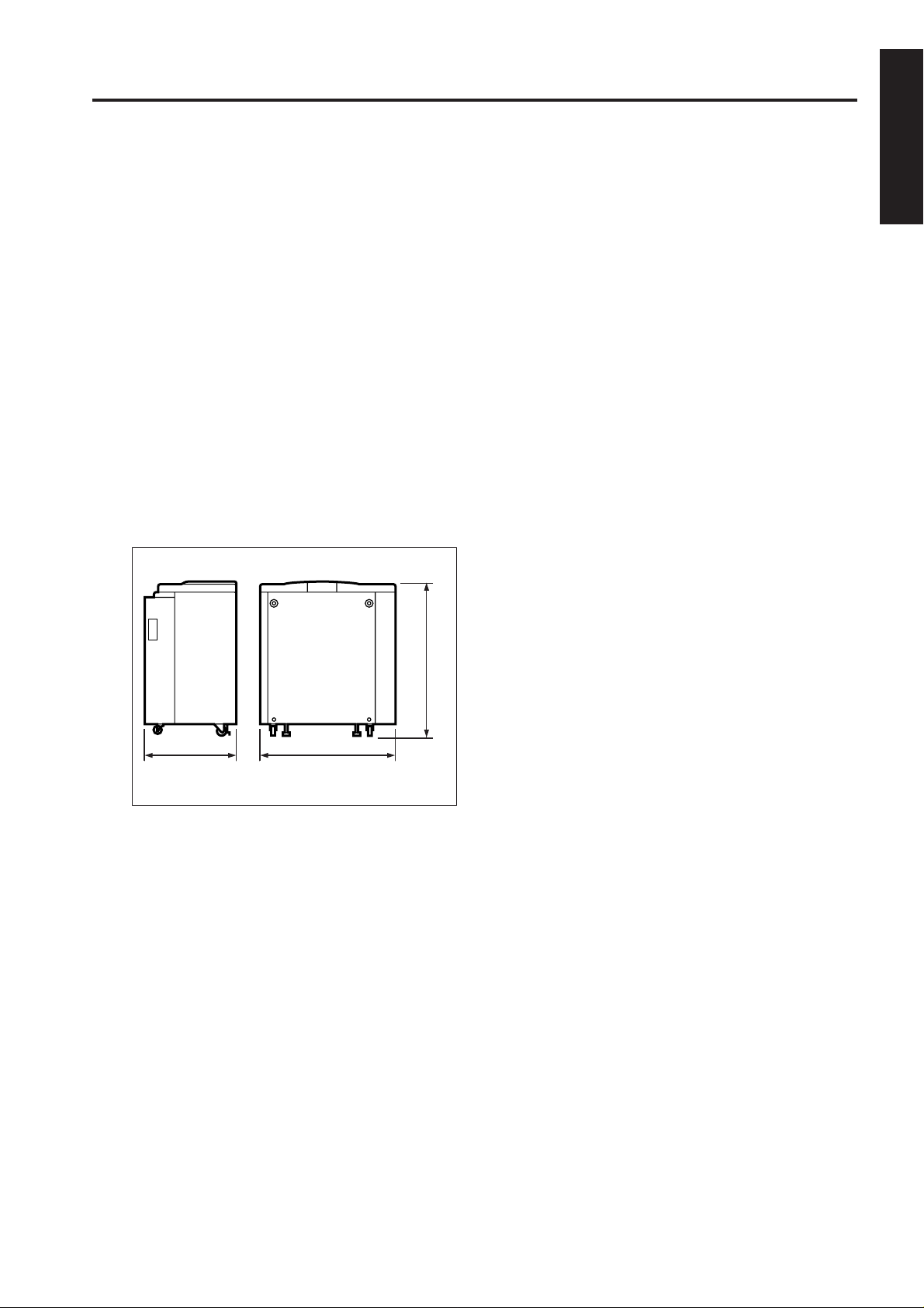
Weight: Approx. 30 kg
Machine dimensions:
82W
1 OUTLINE
430mm
639mm
[4] Maintenance
Maintenance: Same as the main unit
Machine life: Same as the main unit
[5] Operating Environment
Temperature:
10°C to 30°C (50°F to 86°F)
Humidity:
10% to 80%RH
Note: The contents of this manual may change
without prior notice.
690mm
1 - 1
Page 5
LT-401
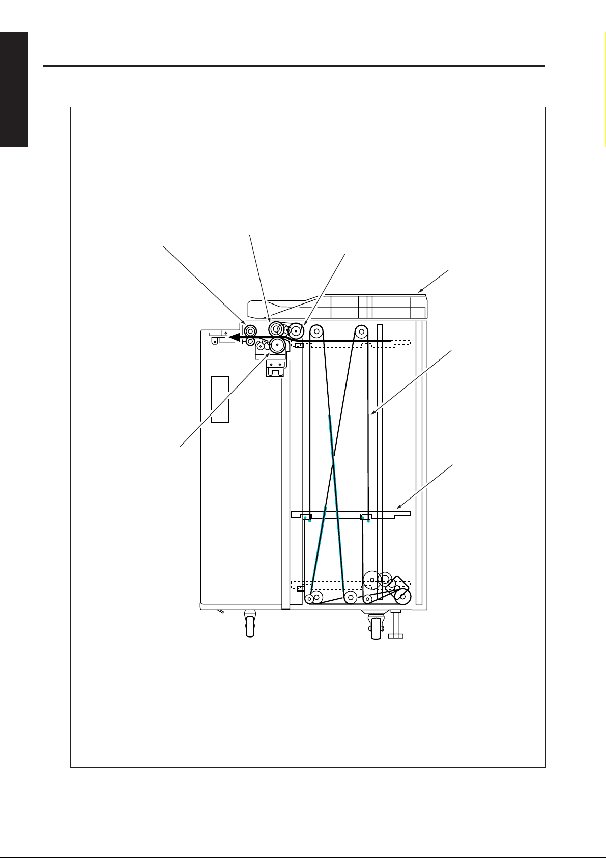
CENTER CROSS SECTION DRAWING
1 OUTLINE
Feed roller
Conveyance roller
Paper feed roller
Top cover
Up/down wire
(the other side
wire as well)
Double feed
prevention roller
Up/down plate
1 - 2
Page 6
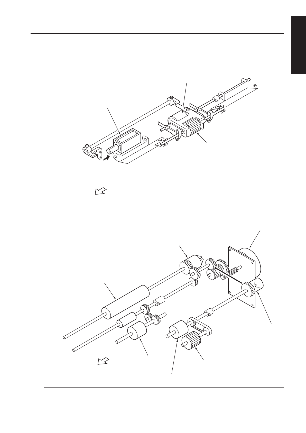
DRIVE SYSTEM DRAWING
LT-401
[1] Paper feed drive unit
LT First paper feed SD
(SD100)
FRONT
1 OUTLINE
Feed roller
Paper feed roller
Conveyance roller
FRONT
LT First paper feed MC
(MC 102)
Double feed
prevention roller
LT paper feed motor
(M101)
LT feed drive MC
(MC101)
Paper feed roller
Feed roller
1 - 3
Page 7
LT-401
1 OUTLINE
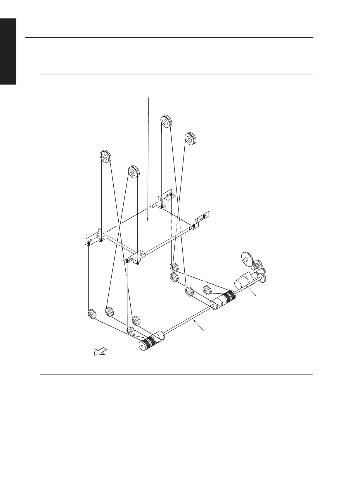
[2] Stacked paper up/down wire drive unit
Up/down plate
FRONT
LT up/down motor
Tray up/down shaft
1 - 4
Page 8

2
UNIT EXPLANATION
2 UNIT EXPLANATION
Page 9

PAPER FEED UNIT
[1] Composition
MC101(LT feed MC)
M101
(LT paper
feed motor)
MC102(LT first paper feed MC)
SD100
(LT first paper feed SD)
Paper dust
removing brush
Conveyance
roller
LT-401
PS106 (LT first paper
feed detection PS)
PS107 (LT first
paper feed PS)
2 UNIT EXPLANATION
Up/down wire
(the other side wire
as well)
M100
(LT up/down
motor)
Remaining paper
detection sensor
actuating gear
[2] Mechanisms
Mechanism Method
*1 Paper lifting Wire drive
Paper feed Paper feed roller
No paper detection Photo sensor (PS108)
+actuator
Paper size detection
*2 Remaining paper Remaining paper de-
detection tection sensor actuating
Paper conveyance Roller transport
Paper size A4, B5, 8.5 x 11
*1: Paper lifting
a. Up/down plate lifting drive operation
The up/down plate is lifted with the up/down wires.
When the top cover closes, M100 (LT up/down
drive motor) rotates and the up/down plate connected to the up/down wires rises.
None
gear+photo sensors
(PS102, PS103, PS10
4, PS105)
Up/down plate (or LT tray)
SW 100 (LT tray down drive switch)
b. Up/down plate down drive operation
The up/down plate automatically lowers by 139
mm when the top cover is opened.
Subsequently , it is lowered b y 139 mm each time
SW100 (LT tray down drive switch) is pressed.
*2: Remaining paper detection
The LT-401 is equipped with a remaining paper
detection sensor actuating gear which rotates
together with M100 (LT up/down motor) driving
the up/down plate.
The remaining paper detection sensor actuating
gear has an actuator to turn ON/OFF PS102 (L T
remaining paper detection PS1), PS103 (LT
remaining paper detection PS2), PS104 (LT
remaining paper detection PS3), and PS105 (LT
remaining paper detection PS4).
2 - 1
Page 10

LT-401
Each sensor is turned ON/OFF according to the
rotating position of the remaining paper detection sensor actuating gear and since this is linked
with the up/down position of the up/down plate,
the remaining paper quantity in the LT-401 can
be determined by monitoring the ON/OFF of each
sensor. The remaining paper quantity detected
with the four sensors is displayed on the main
body display.
M100 (LT up/down motor)
2 UNIT EXPLANATION
Gear for M100
Remaining
paper detection
gear
Actuator
PS102 (LT
remaining paper
detection PS1)
PS103 (LT
remaining
paper
detection
PS2)
PS104 (LT
remaining
paper
detection
PS3)
PS105 (LT
remaining paper
detection PS4)
[3] First paper feed control
LT DB
HTR101
MAIN BODY
HTR101 CONT
AC(H)
24VDC
PGND
5VDC
SGND
LT TXD
LT RXD CLK
LT TXD LATCH
LT TXD CLK
LT ERR
LT RXD
LT ACK
LT REQ
The first paper is fed by MC101 (LT feed) driving the
paper roller and paper feed roller . The feed roller ass'y
is lowered by SD100 (first paper-f eed) to touch the paper when MC101 (LT feed) turns ON and drive SD100
(LT first paper feed). After touching and feeding the
paper, the f eed roller ass'y is r aised by SD100 (LT first
paper feed) to release the feed roller ass'y from the
paper. Then, the paper is fed into the paper conveyance section by the paper feed roller which is driven
by M101 via MC102 (LT first paper feed).
The related signals are: PS100 (LT top cover open/
close detection), PS106 (L T feed detection), PS107 (LT
first paper feed detection), and PS110 (LT jam access
door open/close detection).
5VDC
PS100
SGND
5VDC
PS106
SGND
PS107
5VDC
PS110
SGND
24VDC
MC101 DRIVE
24VDC
MC102 DRIVE
24VDC
SD100 DRIVE
24VDC
M101 CONT
M101 EM
PGND
PS100
PS106
PS107
PS110
MC101
MC102
SD100
MS101 MS102
M101
1. Operation
a. First paper feed timing
(1) Start of first paper feed
At predefined after the copy button is pressed
(2) Start of second and subsequent papers
At predefined interval after PS106 (L T first paper
feed detection) is turned OFF by the previous
paper
2 - 2
Page 11

LT-401
(3) OFF timing
At predefined interval after PS106 is turned OFF
by the last paper
b. Interlock
The power supply line of M101 (LT paper feed)
is equipped with MS101 (LT interlock MS1) and
MS102 (LT interlock MS2). When the top cover
is opened, MS101 turns OFF, and when the jam
access door is opened MS102 turns OFF , thereby
cutting off the power supply to M101.
Furthermore, the top cover is equipped with
PS100 (LT top cover open/close detection) and
the jam access door is equipped with PS110 (LT
jam access door open/close detection) and when
either of these doors is opened during paper feed,
the M101 drive signal is turned OFF to stop the
paper feed operation.
c. Internal heater
The LCT is equipped with HTR101 (LT internal
heater) to protect the paper from humidity.
HTR101 is directly controlled by the main body
ACDB (AC drive board) r ather than b y the LTDB
(LT drive board).
2. Signals
a. Input signals
(1) PS100 (PS100 to LTDB)
Top cover open/close detection signal
[L]: Cover opened
[H]: Cover closed
(2) PS106 (PS106 to LTDB)
Transport roller exit paper detection signal
[L]: Paper detected
[H]: Paper not detected
(3) PS107 (PS107 to LTDB)
Transport roller entrance (pre-registration
position) paper detection signal
[L]: Paper detected
[H]: Paper not detected
(4) PS110 (PS110 to LTDB)
Jam access door open/close detection signal
[L]: Cover closed
[H]: Door not opened
(5) M101 EM (M101 to LTDB)
M101 rotation error detection signal
[L]: M101 rotating
[H]: M101 not rotating
(6) LT TXD (MAIN BODY to LTDB)
Serial data to transmit main body PRCB operating
status to LTDB
(7) LT TXD LATCH (MAIN BODY to LTDB)
LT TXD signal latch signal
(8) LT TXD CLK (MAIN BODY to LTDB)
LT TXD signal clock signal
(9) LT ERR (MAIN BODY to LTDB)
Signal to notify LTDB when there is error in the
main body
(10)LT ACK (MAIN BODY to LTDB)
Serial data transmission enable signal from LCT
to main body PRCB
b. Output signal
(1) MC101 DRIVE (LTDB to MC101)
MC101 ON/OFF drive signal
[L]: MC101 ON
[H]: MC101 OFF
(2) MC102 DRIVE (LTDB to MC102)
MC102 ON/OFF drive signal
[L]: MC102 ON
[H]: MC102 OFF
(3) SD100 DRIVE (LTDB to SD100)
SD100 ON/OFF drive signal
[L]: SD100 ON
[H]: SD100 OFF
(4) M101 CONT (LTDB to M101)
M101 ON/OFF control signal
[L]: M101 ON
[H]: M101 OFF
(5) LT RXD (LTDB to MAIN BODY)
Serial data to transmit the L TDB operating status
to main body PRCB
(6) LT RXD CLK (LTDB to MAIN BODY)
LT RXD signal clock signal
(7) LT REQ (LTDB to MAIN BODY)
Serial data send request signal from LCT to main
body PRCB
2 UNIT EXPLANATION
2 - 3
Page 12

LT-401
[4] Up/down plate drive control
LT DB
MAIN BODY
2 UNIT EXPLANATION
24VDC
PGND
5VDC
SGND
LT TXD
LT RXD CLK
LT TXD LA TCH
LT TXD CLK
LT ERR
LT RXD
LT ACK
LT REQ
When the top cover opens or closes, M100 (LT up/
down motor) rotates forward or backward to move the
up/down plate up or down. The up/down plate
descends by 139 mm each time SW100 (LT tray do wn
drive switch) is pressed while the top cov er is opened.
The related signals are PS100 (L T top cov er open/close
detection), PS101 (LT tray bottom limit detection), and
PS109 (LT tray top limit detection).
1. Operation
a. Up/down plate descend timing
(1) ON timing
When the top cover is opened and PS100 is
turned OFF, M100 rotates backward to lo wer the
up/down plate.
(2) OFF timing
M100 turns OFF at predefined interval after
PS100 turns OFF or SW100 turns ON. This in
turn lowers the up/down plate by 139 mm.
(3) Others
The up/down plate descends by 139 mm each
time SW100 is pressed until PS101 turns ON to
indicate the bottom limit of the up/down plate.
5VDC
PS100
SGND
5VDC
PS101
SGND
SW100
5VDC
PS109
SGND
M100 DRIVE
M100 DRIVE
PS100
PS101
SW100
PS109
M100
b. Up/down plate ascend timing
(1) ON timing
When the top cover is closed and PS100 is turned
ON, M100 rotates forward to raise the up/down
plate.
(2) OFF timing
When the up/down plate rises and PS109 (LT
tray upper limit detection) turns ON to indicate
the detection of the topmost paper, M100 turns
OFF and stops the up/down plate.
The up/down plate also stops when the top cover
is opened and PS100 turns OFF.
2. Signals
a. Input signals
(1) PS101 (PS101 to LTDB)
Up/down plate bottom limit detection signal
[L]: Up/down plate not at lower limit
[H]: Up/down plate at lower limit
(2) PS109 (PS109 to LTDB)
Up/down plate top limit detection signal
[L]: Up/down plate not at upper limit
[H]: Up/down plate at upper limit
(3) SW100 (SW100 to LTDB)
SW100 ON/OFF detection signal
[L]: SW100 ON
[H]: SW100 OFF
b. Output signals
(1) M100 DRIVE1, 2 (LTDB to M100)
M100 drive signal
These signals switches the direction of the drive
current to control the rotation direction of M100.
2 - 4
Page 13

LT-401
[5] Remaining paper detection/No paper
detection control
LT DB
MAIN BODY
24VDC
PGND
5VDC
SGND
LT TXD
LT RXD CLK
LT TXD LA TCH
LT TXD CLK
LT ERR
LT RXD
LT ACK
LT REQ
The remaining paper quantity is detected by PS102
(LT remaining paper detection 1), PS103 (LT remaining paper detection 2), PS104 (LT remaining paper
detection 3), and PS105 (LT remaining paper detection 4) and no paper detection is made by PS108 (LT
no paper detection).
The signals detected by these sensors are controlled
by LTDB (LT drive board) and displayed on the main
body display.
1. Operation
a. Remaining paper detection control
The remaining paper quantity is determined from
the ON/OFF combination of sensors PS102,
PS103, PS104, and PS105 which detect the
rotational position of M100 that is driving the up/
down plate. Each sensor turns ON or OFF according to the position of the remaining paper
detection sensor actuating gear which is linked
with the rotation of M100.
The remaining paper quantity is detectable at
eight levels, but it is displayed on the main body
display as five levels.
5VDC
PS102
SGND
5VDC
PS103
SGND
5VDC
PS104
SGND
5VDC
PS105
SGND
5VDC
PS108
SGND
M100 DRIVE
M100 DRIVE
PS102
PS103
PS104
PS105
PS108
M100
<Remaining paper quantity and display>
Stacked
paper
quantity
0~700
701~1200
1201~1700
1701~2200
2201~2700
2701~3200
3201~3700
3701 or
PS102 PS103 PS104 PS105
OFF
OFF
OFF
ON
OFF
OFF
ON
ON
OFF
ON
ON
ON
ON
ON
ON
OFF
ON
ON
OFF
OFF
ON
OFF
OFF
OFF
Remaining
paper quantity
display
OFF
1 flashing
OFF
1 on
OFF
2 on
OFF
2 on
ON
3 on
ON
3 on
ON
4 on
ON
4 on
more
Caution:
The remaining paper quantity is indicated on
the control panel with four horizontal bars.
Stacked paper quantity diff ers depending on
the thickness of the paper.
b. No paper detection control
When there is no more paper inside the LCT,
PS108 turns ON and a message is displayed on
the main body display.
2. Signals
a. Input signals
(1) PS102 (PS102 to LTDB)
Remaining paper detection sensor actuating gear
rotational position detection signal
[L]: PS102 OFF
[H]: PS102 ON
(2) PS103 (PS103 to LTDB)
Remaining paper detection sensor actuating gear
rotational position detection signal
[L]: PS103 OFF
[H]: PS103 ON
(3) PS104 (PS104 to LTDB)
Remaining paper detection sensor actuating gear
rotational position detection signal
[L]: PS104 OFF
[H]: PS104 ON
(4) PS105 (PS105 to LTDB)
Remaining paper detection sensor actuating gear
rotational position detection signal
[L]: PS105 OFF
[H]: PS105 ON
(5) PS108 (PS108 to LTDB)
LCT no paper detection signal
[L]: No paper
[H]: Paper present
2 UNIT EXPLANATION
2 - 5
Page 14

3
DISASSEMBLY/ASSEMBLY
3 DIS./ASSEMBLY
Page 15

3 DIS./ASSEMBLY
This section explains how to disassemble and reassemble the machine.
When disassembling and reassembling the machine, follow the
precautions given below.
1. Be sure the power cord has been unplugged from the wall outlet.
2. The disassembled parts must be reassembled following the
disassembly procedure in reverse unless otherwise specified.
3. Care should be taken not to lose small parts. Care should also be
taken not to install small parts in wrong places.
4. Do not operate the machine before installing all the disassembled
parts completely .
5. Removal of some screws is prohibited in this section. Never loosen
them.
Page 16

PAPER FEED SECTION
LT-401
[1] Cleaning the Paper Dust Removing
Brush
Caution: If LT is connected to the main
unit, make sure that main unit
power plug is disconnected
from the power outlet.
a. Procedure
(1) Open the top cover.
(2) Remove the two screws to detach the paper feed
cover B.
Top
cover
Screws (2)
Paper feed cover B
[2] Cleaning the PS106 (LT feed PS)/
PS107 (LT first paper feed PS)
Caution: If LT is connected to the main
unit, make sure that main unit
power plug is disconnected
from the power outlet.
a. Procedure
(1) Looking into the paper ejection side of the LT-401
from below, and clean sensors through the cavity
for PS106 and the cavity for PS107 using a
blower brush or the like.
Cavity for PS106
Cavity for PS107
Paper
exit
side
3 DIS./ASSEMBLY
(3) Insert a flat bladed screwdriver in the slots (in two
locations) for paper dust removing brush to release the locking lugs, then remove the paper
dust removing brush.
Paper dust removing
brush
Cavity
Locking lugs
(4) Clean the paper dust removing brush using a
blower brush or the like.
(5) Reinstall the above parts following the removal
steps in reverse.
[3] Removing and Reinstalling
the Paper Feed Roller Unit
Caution: If LT is connected to the main
unit, make sure that main unit
power plug is disconnected
from the power outlet.
a. Procedure
(1) Open the top cover.
(2) Remove the spring from the paper feed roller unit.
Top cover
Spring
Remove
this.
Paper feed roller
unit
Paper feed roller unit
3 - 1
Page 17

LT-401
(3) After removing the two retaining rings, remove
the two bearings outward to remove the paper
feed roller unit.
Paper feed roller unit
Bearing
Retaining ring
(4) Reinstall the above parts following the removal
3 DIS./ASSEMBLY
Retaining ring
steps in reverse.
[4] Replacing the Paper feed Roller
Rubber/Feed Roller Rubber
Caution: If LT is connected to the main
unit, make sure that main unit
power plug is disconnected
from the power outlet.
a. Procedure
(1) Remove the paper feed roller unit.
(2) Remove the bearing and paper feed reference
actuator.
Bearing
(3) Remove the two retaining rings.
(4) Remove the bearing outward to detach the roller
section from the roller fitting.
Roller fitting
Retaining
ring
Bearing
Bearing
(5) Remove the bearing from the opposite side of the
coupling, then remove the paper feed roller from
the shaft.
(6) Remove the retaining ring to pull the feed roller
from the shaft.
(7) Remove the rubber from each roller.
Paper feed roller rubber
Paper feed
roller
Shaft
Coupling
Paper feed reference actuator
Bearing
3 - 2
Bearing
Retaining
ring
Shaft
Feed roller
rubber
Feed roller
Paint
mark
Page 18

LT-401
(8) Reinstall the above parts following the removal
steps in reverse.
Caution 1: Make sure rollers and rubber por-
tions are oriented properly when
reinstalling them.
Caution 2: Make sure the one-way clutch
direction is correct.
Caution 3: Check whether grease or the like
is present on each roller.
[5] Replacing the Double Feed
Prevention Roller
Caution: If LT is connected to the main
unit, make sure that main unit
power plug is disconnected
from the power outlet.
a. Procedure
Caution: With the power held on, press the
SW100 (L T tra y down s witch) to move
the up/down plate down to the bottom
in advance.
(1) Remove the paper feed roller unit.
(2) Remove the two screws to detach the double
feed prevention roller unit cover.
(3) Remove the two screws to detach the double
feed prevention roller unit.
Caution: When reinstalling the double feed
prevention roller unit, tighten the
screws on the rear side first.
Double feed prevention roller unit
Screws
(4) Remove the two retaining rings, fit the shaft into
the D-cut in the fitting, and remove the double
feed prevention roller together with the shaft.
3 DIS./ASSEMBLY
Double feed
prevention roller
Double feed
prevention roller
unit cover
Screws
Double feed
prevention roller
D-cut
Retaining ring
3 - 3
Page 19

LT-401
(5) Remove the double feed prevention roller rubber
from the double feed prevention roller.
Paint mark
Double feed
prevention roller
Double feed
prevention roller
rubber
(6) Reinstall the double feed prevention roller in the
3 DIS./ASSEMBLY
reverse order of the removal procedure.
Caution 1: Make sure the double feed pre ven-
tion roller rubber is oriented
properly when reinstalling it.
Caution 2: Check whether scratch or like is
visible on the pet cock for the
drive gear.
Caution 3: Check whether grease or the like
is present on double feed roller.
[6] Replacing MC101 (LT feed MC)/
MC102 (LT first paper feed MC)
a. Procedure
(1) Open the top cover.
(2) Remove the spring from the paper feed roller unit.
(3) Remove the two screws to detach the top cover.
Top cover
Screws
Shaft
(4) Remove the two screws to detach the clutch
replacement cover.
Clutch replacement
cover
3 - 4
Screws
Page 20

LT-401
(5) Disconnect two relay connectors (CN765, CN766)
of the clutches.
(6) Remove the Retaining ring to detach each clutch.
MC101 (LT Paper feed MC)
Retaining
ring
Relay
connector
(CN766)
MC102 (LT first
paper feed MC)
Retaining
ring
Relay connector
(CN765)
(7) Reinstall the above parts following the removal
steps in reverse.
Caution: When installing each MC, make
sure that the stopper of each clutch
is on the predefined position.
(3) Remove four screws to detach the right side
cover.
Screws
Right side
cover
Screws
(4) After opening the jam access door, remove four
screws to detach the front cover.
Caution: Remove four screws and then
remove the front cover with the
jam access door closed.
3 DIS./ASSEMBLY
[7] Replacing the Up/down Wires
a. Procedure
Caution: With the power held on, press the
SW100 (L T tra y down s witch) to move
the up/down plate down to the bottom
in advance.
(1) Open the top cover.
(2) Remove the clutch replacement cover.
Jam access door
Screws
Screws
Right side cover
3 - 5
Page 21

LT-401
(5) Remove the five screws to detach the rear cover.
Screw
(6) Remove the five relay connectors (CN749,
CN780, CN781, CN782, CN783) to disconnect
3 DIS./ASSEMBLY
the wiring harness from the up/down motor mount-
ing plate.
(7) Remove the E-ring to detach the up/down gear.
(8) Pull the pin from the shaft.
(9) Remove the E-ring to detach the bearing.
(10)Remove the three screws to detach the up/down
motor assembly.
Screw
Rear cover
Screw
(11)Replace the up/down wire following the instruc-
tions in “Removing Up/Down Wires” and “Installing Up/Down Wires.”
Caution: Four up/down wires with different
length, two at the front and two at the
back, are used. Wires with the same
length can be used either at the front
or back if they are used in the same
location.
Wire A
Wire B
Wire C
Wire D
Up/down
motor
assembly
Shaft
Relay connector
(CN749)
Screw
Screw
Pin
Relay
connector
(CN780)
Bearing
Relay
connector
(CN781)
Relay
connector
(CN782)
Relay
connector
(CN783)
Screw
E-ring
Up/down
gear
E-ring
3 - 6
Page 22

<Removing the up/down wire >
LT-401
Up/down plate
14.Release the metal
ball and remove
wire A.
7. Release the metal
ball and remove
wire C.
9. Release the metal
ball and remove
wire D.
12.Release the metal
ball and remove
wire B.
Wire A
Wire B
Wire B
Wire A
Wire D
Wire C
2. Release the metal
ball and remove
wire C.
18.Release the metal
ball and remove
wire A.
4. Release the metal
ball and remove
wire D.
16.Release the metal
ball and remove
wire B.
1. Remove the E ring.
3. Remove the pulley.
5. Remove the pulley.
3 DIS./ASSEMBLY
Wire C
Wire D
6. Remove the E ring.
8. Remove the pulley.
10.Remove the pulley.
11.Remove the E ring,
pulley, and release
wire B.
FRONT
13.Remove the pulley
and release wire A.
Tray
up/down
shaft
15.Remove the E
ring, pulley, and
release wire B.
17.Remove the pulley
and release wire A.
3 - 7
Page 23

LT-401
<Installing up/down wire>
7. Pass wire A through
15. Pass wire C through
each pulley and
attach the metal ball.
12. Pass wire D through
3 DIS./ASSEMBLY
10. Pass wire B through
Wire A
Wire B
each pulley and
attach the metal ball.
each pulley and
attach the metal ball.
each pulley and
attach the metal ball.
Wire C
Wire D
Wire B
Wire A
FRONT
Up/down plate
Tray up/down
shaft
20. Pass wire B through each
pulley and attach the
metal ball.
2. Pass wire A through each
pulley and attach the
metal ball.
17. Pass wire D through each
pulley and attach the
metal ball.
5. Pass wire B through each
pulley and attach the
metal ball.
Wire D
Wire C
18. Insert wire C in tray
up/down shaft to
attach the pulley and
fasten with E ring.
13. Insert wire C in tray
up/down shaft to
attach the pulley and
fasten with E ring.
14. Wind wire C six times
around the pulley so
that it pulls out the
top.
six times
11. Insert wire D in tray
up/down shaft, attach
the pulley, and then
wind wire D six times
around the pulley so
that it pulls out the
top.
six times
1. Insert wire A in
tray up/down
6.
shaft to attach
the pulley and
then pull out
wire A from the
bottom.
3. Insert wire B in tray
up/down shaft to attach
8.
the pulley and fasten with
E ring.
4. Pull out wire B from under
the pulley.
9.
19. Wind wire C six
times around the
pulley so that it pulls
out the top.
six times
16. Insert wire D in tray
up/down shaft, attach
the pulley, and then
wind wire D six times
around the pulley so
that it pulls out the
top.
six times
3 - 8
Page 24

(12)After installing the up/down wires, make sure the
up/down wires are passed in the grooves in the
pulleys properly and wires do not run on the sides
of the pulleys. Also make sure the up/down plate
can be moved up and down smoothly by hand.
Caution: If the up/down plate does not move
up and down smoothly , replace the up/
down wires.
(13)Install the up/down wire drive motor assembly,
up/down gear, and relay connectors, following
the removal steps in reverse.
(14)Remove the E-ring to detach the idle gear.
(15)Rotate the remaining paper detection gear until
the round hole in this gear is aligned with the
oblong hole in the up/down motor mounting plate.
Up/down motor
mounting plate
Remaining paper
detection gear
LT-401
Round
Oblong
hole
E-ringIdle gear
hole
(16)Install the idle gear.
(17)Attach the covers following the removal steps in
reverse.
Caution: After replacing the up/down wires,
correct inclination and deviation of the
up/down plate. (Refer to “ADJUSTMENT.”)
3 DIS./ASSEMBLY
3 - 9
 Loading...