

Page 1

4
ELECTRIC PARTS LIST
ELECTRIC PARTS LIST
4
Page 2
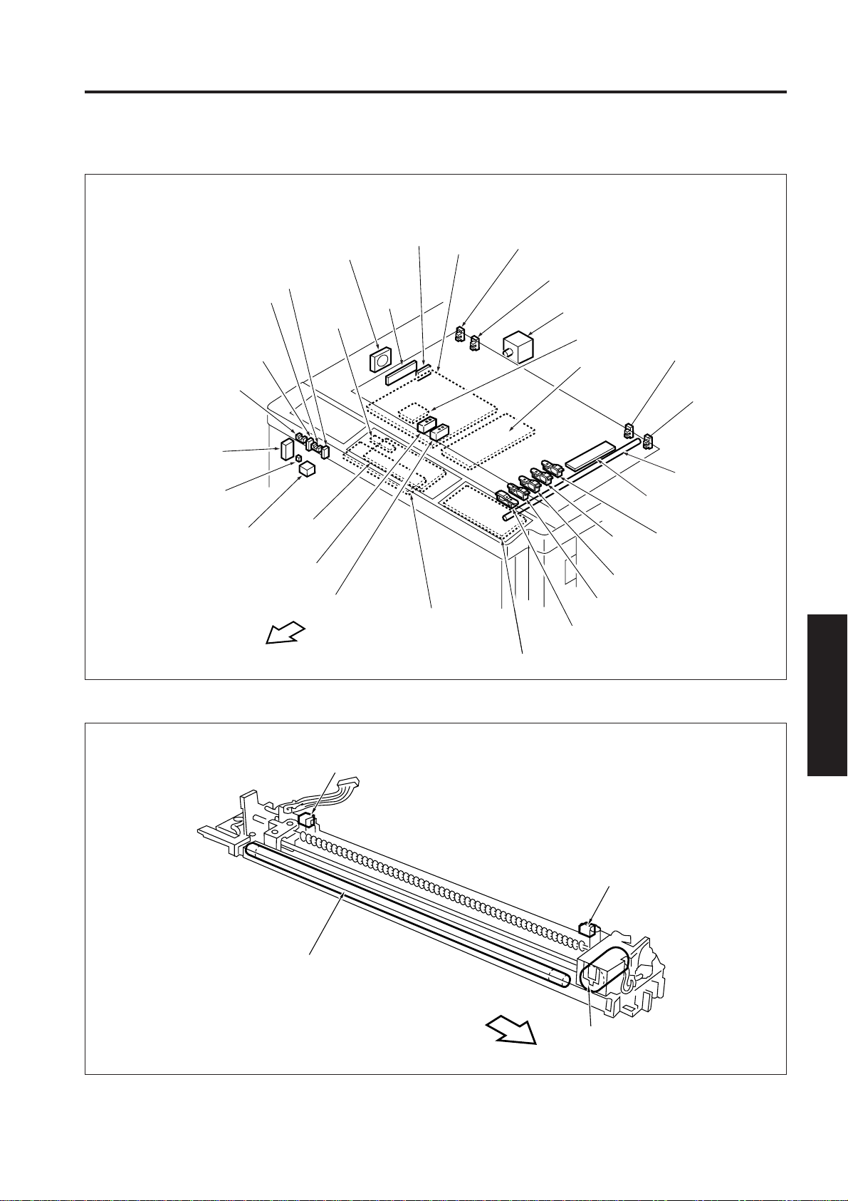
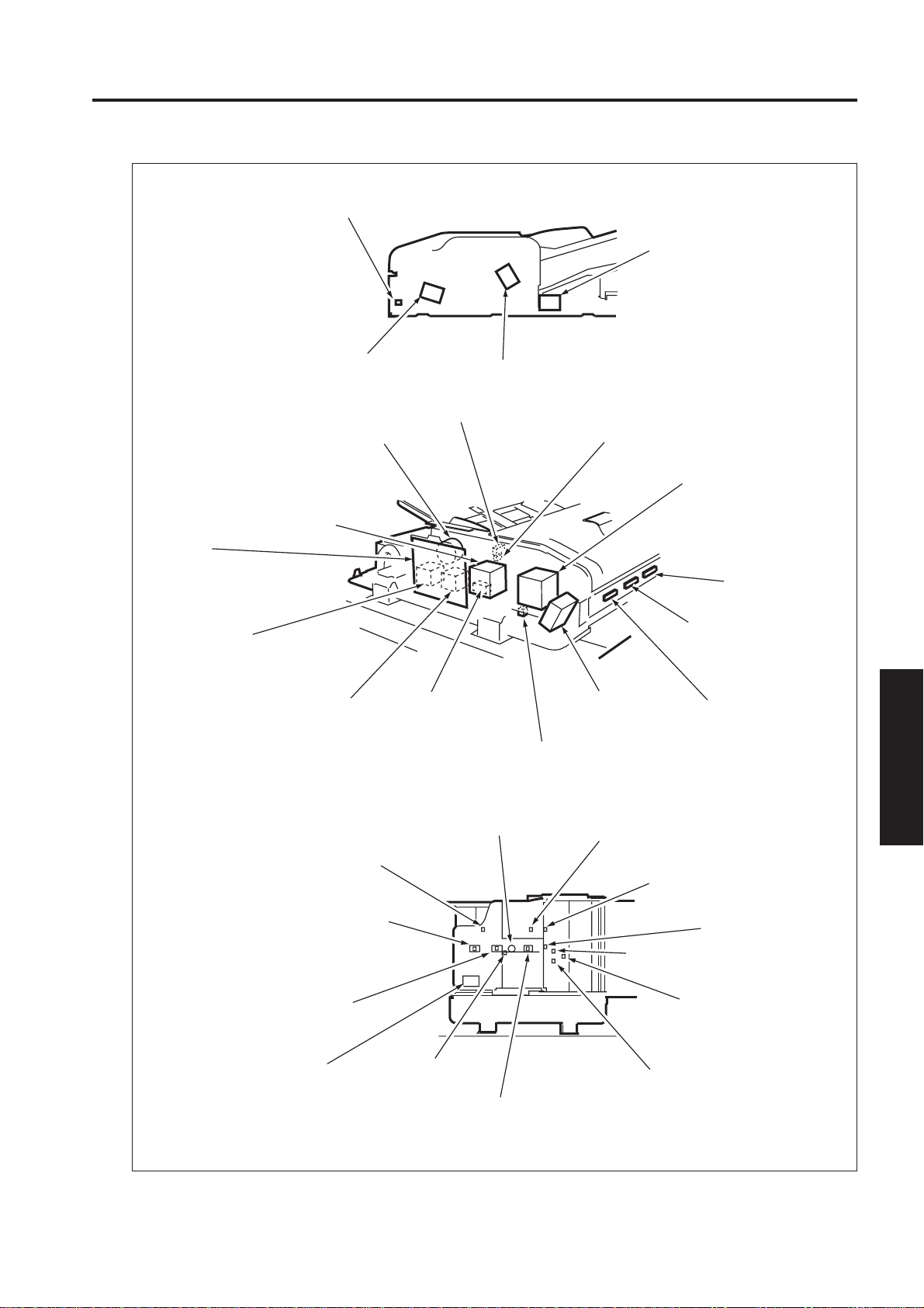
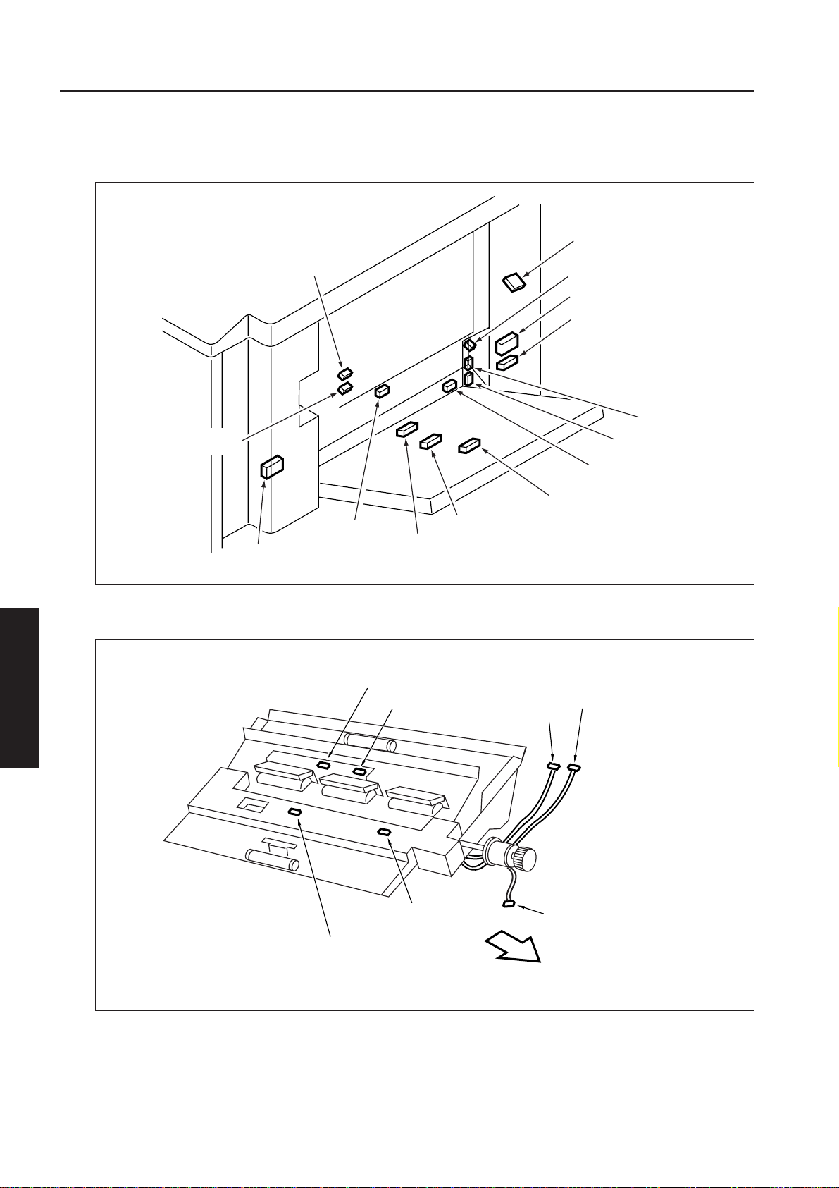
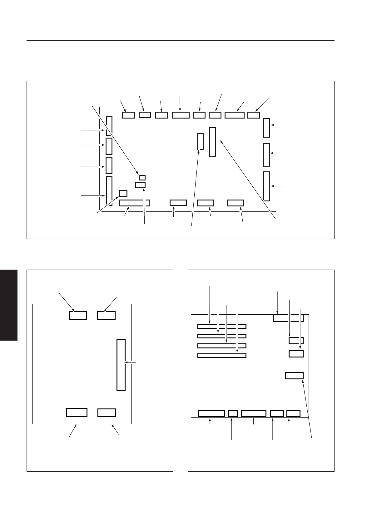
7075 PARTS LAYOUT DRAWING
7075 ELECTRICAL PARTS LAYOUT DRAWING
[1] Read Section/Operational Section
ICB
PS24
Front door open/close
detection PS1
MS2
Interlock 2
PS25
Front door open/close
detection PS2
SW1
Main switch
SW2
Reset switch
C(T)
Total counter
FM7
Scanner cooling fan
MS1
Interlock 1
OB INVB
OB Inverter
board
LCD
Indicator
board
PS63
APS sensor 2
PS62
APS sensor 1
FRONT
Image
control
board
ADB
A/D
converter
board
OB1
Operation board 1
OP IFB
Optional I/F
board
PS7
ADF brake PS
PS5
Scanner HP PS
M13
Scanner drive motor
MB
Memory board
ICB IFB
ICB I/F board
PS67
APS sensor 6
PS65
APS sensor 4
OB2
Operation board 2
PS6
Original HP PS
L1
Exposure lamp
L1 INVB
L1 Inverter
PS68
PS66
APS sensor 5
PS64
APS sensor 3
APS sensor 7
Scanner
reverse PS
[2] Charging Corona Wire Unit
PS41
Charging wire cleaning pad HP PS
PCL
Pre-charging exposure lamp
FRONT
ELECTRIC PARTS LIST
4
PS42
Charging wire cleaning pad limit PS
M23
Charger cleaning motor
4 - 1
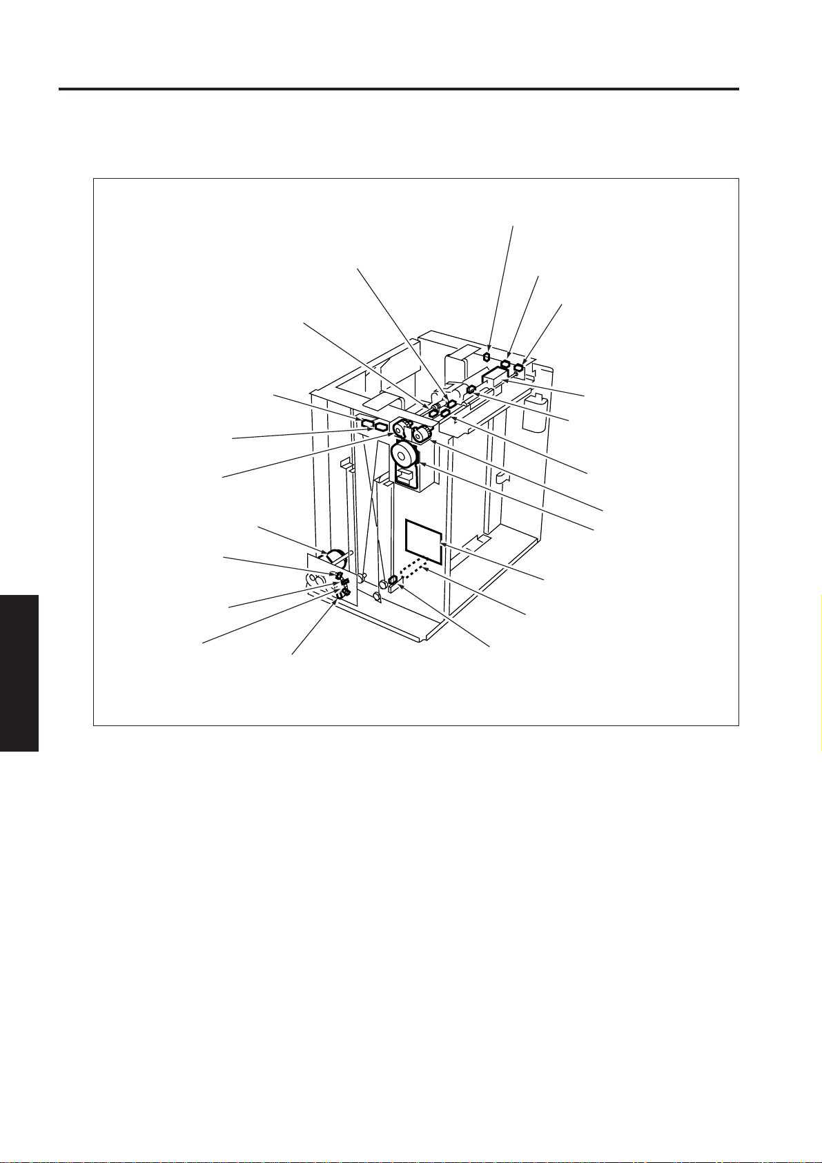
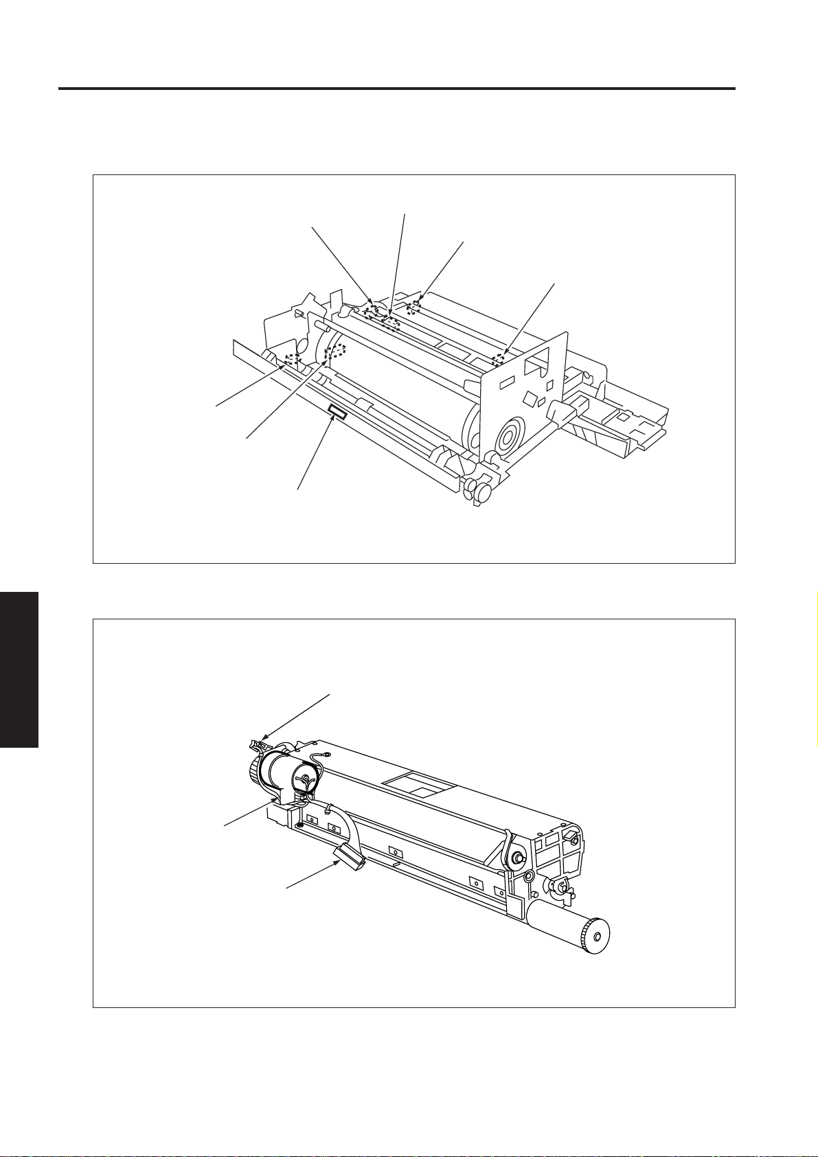
Page 3
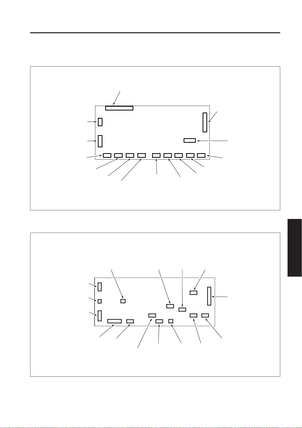
7075 PARTS LAYOUT DRAWING
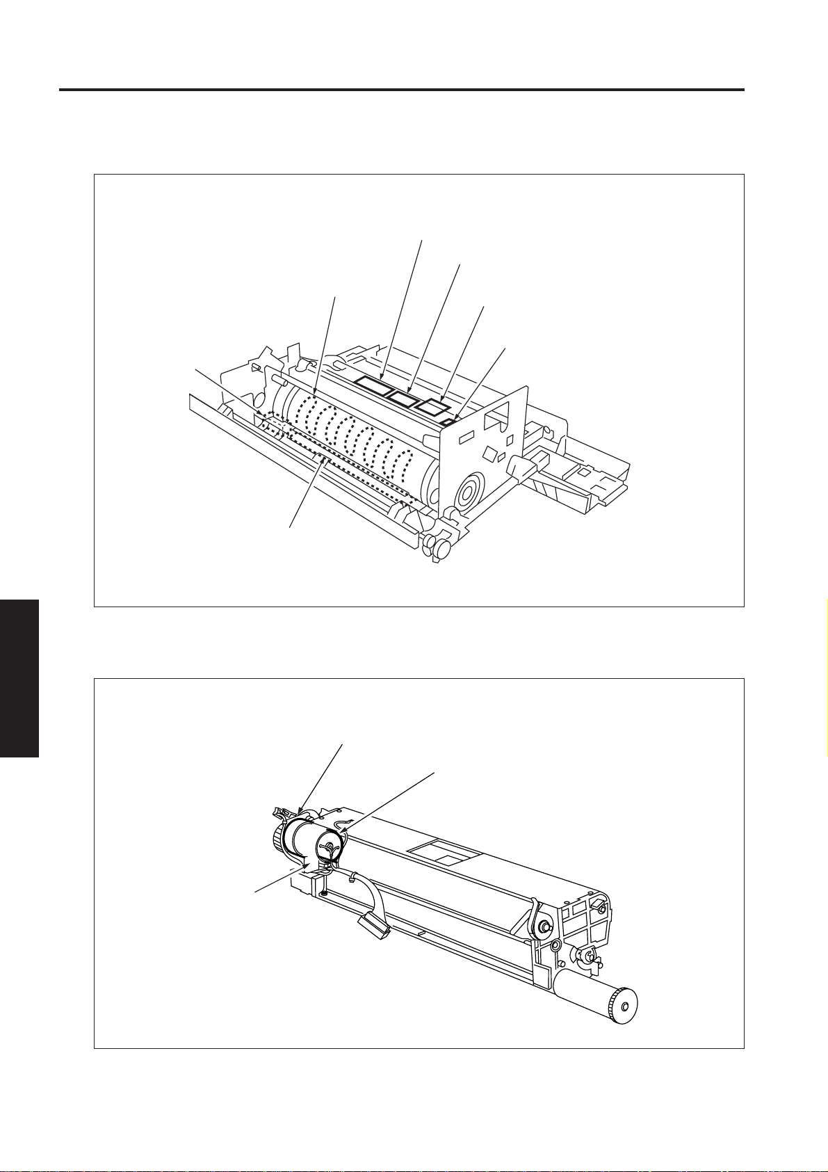
[3] Drum Unit
HTR1
Drum heater
DPSB
Drum potential sensor board
DPS
Drum potential sensor
DTSB
Drum temperature sensor board
SD4
Separation claw SD
[4] Cleaning Unit
ELECTRIC PARTS LIST
4
TH5
Drum temperature sensor
TCSB
Toner control sensor board
PS30
Blade PS1
M14
Blade motor
PS31
Blade PS2
4 - 2
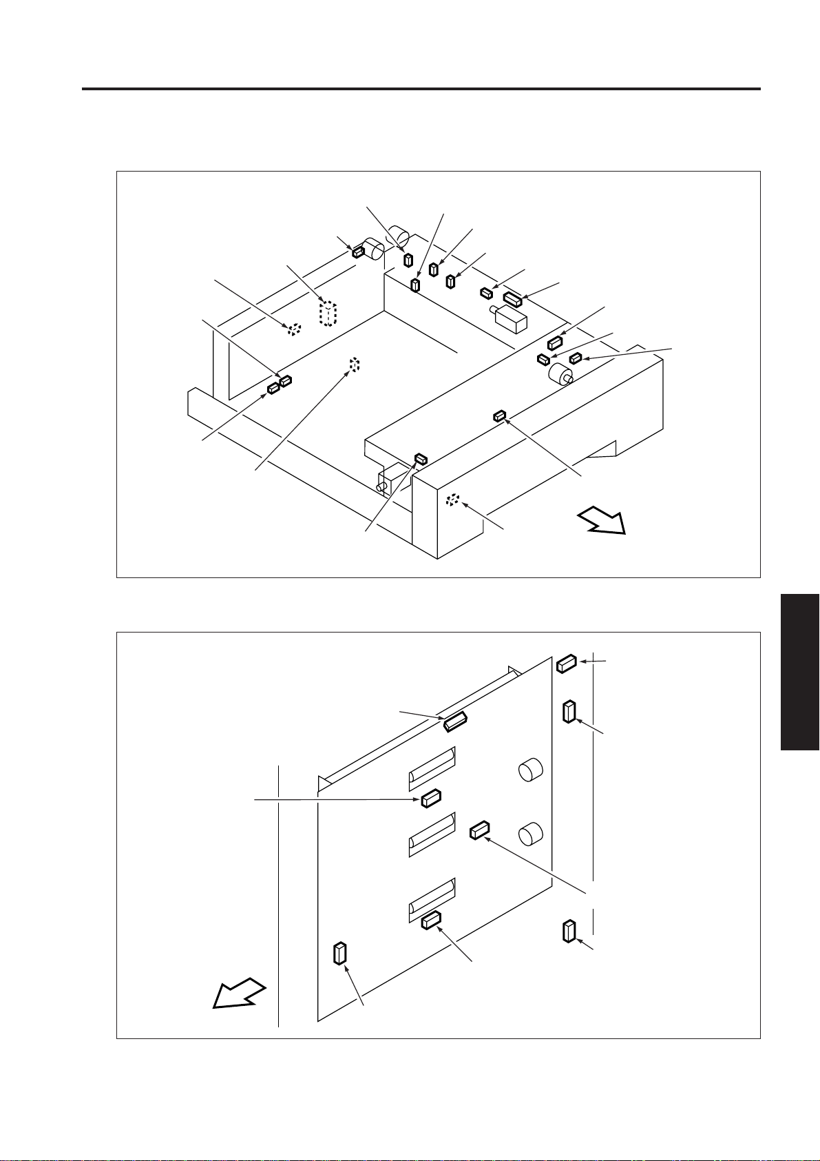
Page 4
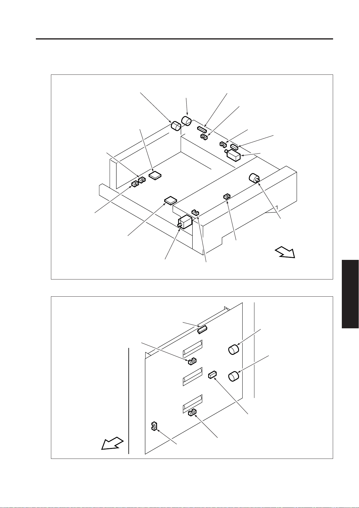
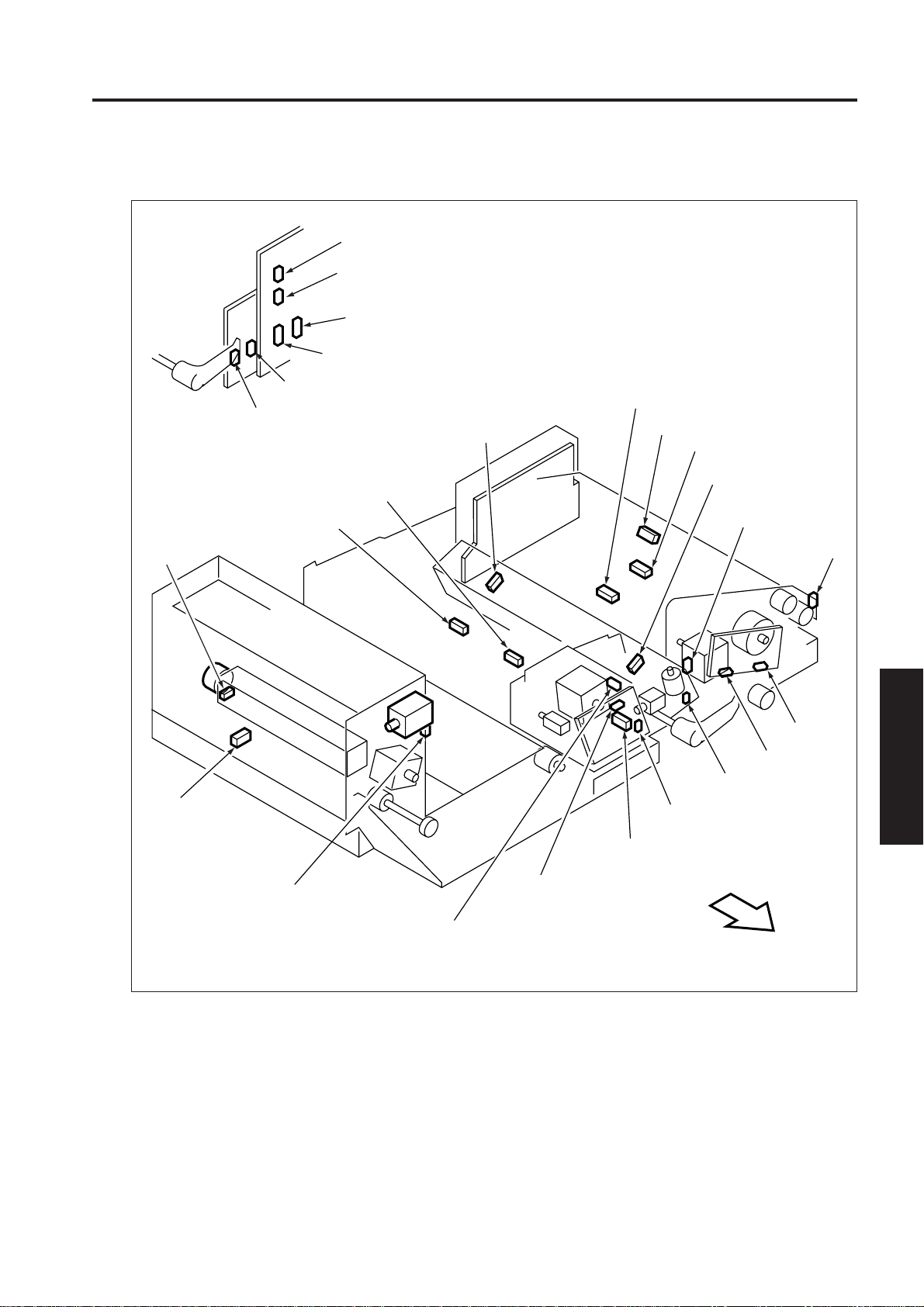
[5] Tray 1,2,3
7075 PARTS LAYOUT DRAWING
PS33/36/39
Paper size detection
PS2-1/2/3
PS32/35/38
Paper size detection
PS1-1/2/3
VR1/2/3
Paper size detection VR 1/2/3
MC3/5/7
Feed clutch 1/2/3
HTR2/3/4
Tray heater 1/2/3
MC4/6/8
Pre-registration clutch 1/2/3
SD5/6/7
Lock Solenoid 1/2/3
PS48/50/52
Paper pre-registration PS 1/2/3
PS26/27/28
No paper PS 1/2/3
PS20/21/22
Tray upper limit PS 1/2/3
PS47/49/51
Paper feed PS 1/2/3
SD8/9/10
Pick up SD 1/2/3
M19/20/21
Up drive motor 1/2/3
PS14/15/16
Handle release PS
1/2/3
PS34/37/40
Remaining paper detection PS 1/2/3
FRONT
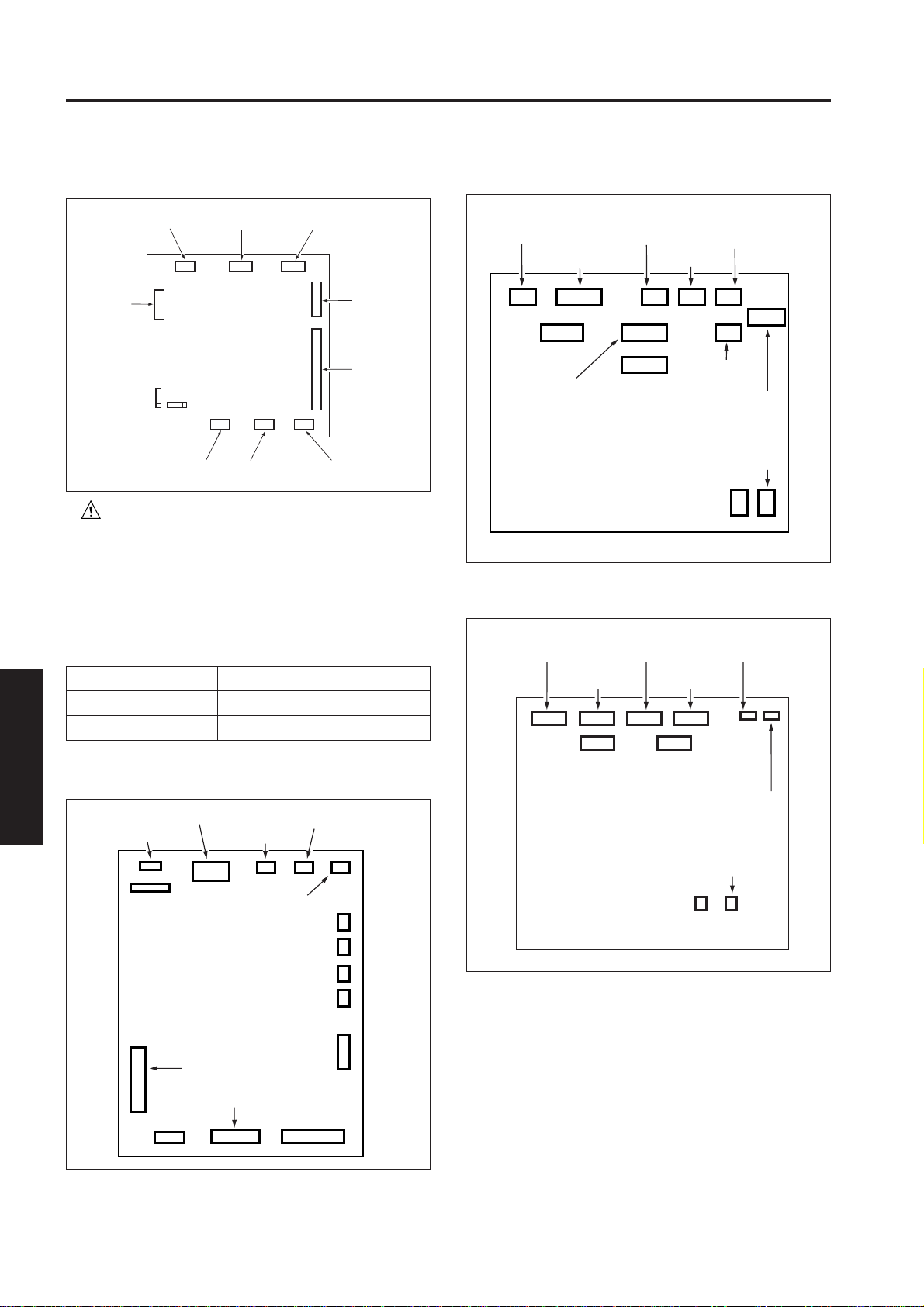
[6] Vertical Conveyance Section
PS18
Vertical conveyance PS1
FRONT
PS54
Loop PS
PS19
PS17
Open/close detection PS
Vertical conveyance PS3
MC9
Vertical conveyance
clutch1
MC10
Vertical conveyance
clutch 2
PS53
Vertical conveyance PS2
ELECTRIC PARTS LIST
4
4 - 3
Page 5

7075 PARTS LAYOUT DRAWING
[7] By-pass Feed Section
PS23
Tray upper limit PS (by-pass)
FM5
Write section
cooling fan 1
FM8
Write section
cooling fan 2
SD11
Pick up SD (by-pass)
M22
Up/down motor (by-pass)
PS43
Tray lower limit PS
(by-pass)
PS29
No paper PS (by-pass)
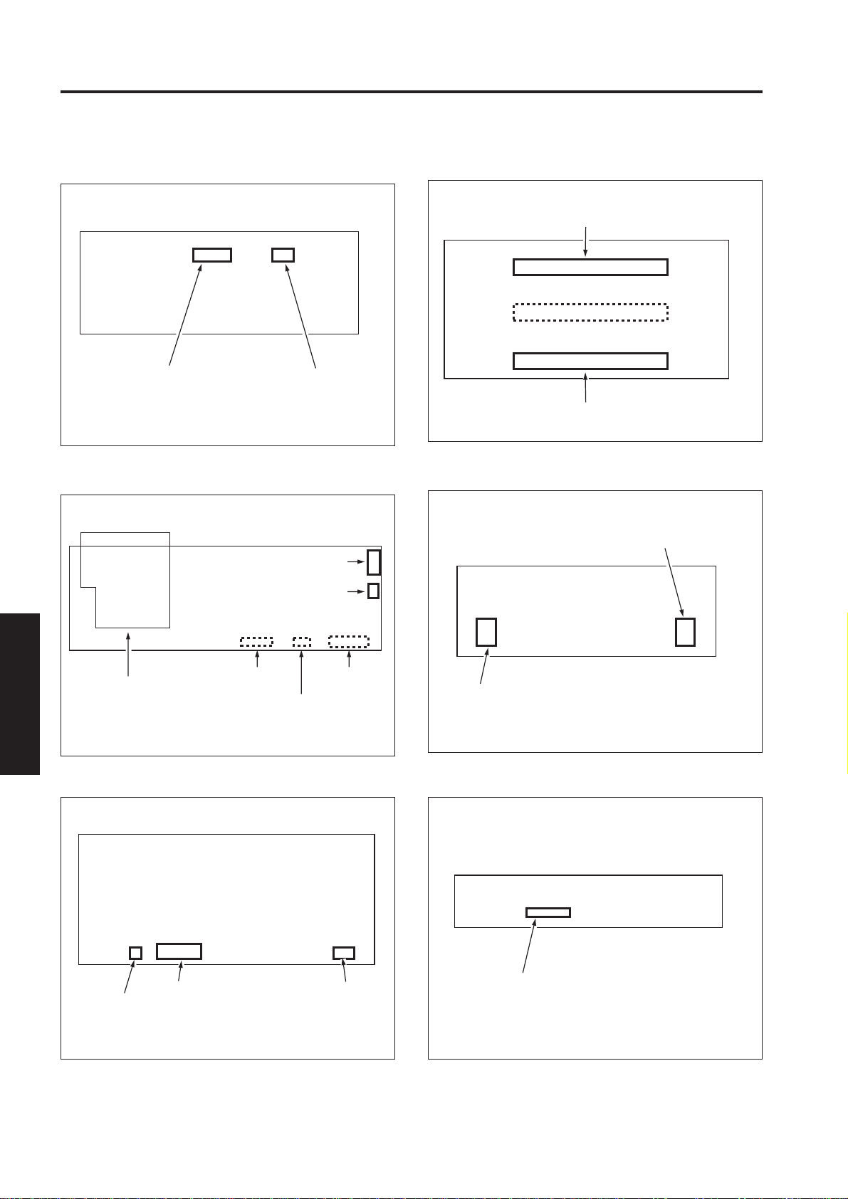
[8] Second Paper Feed Section
ELECTRIC PARTS LIST
4
PS45
Leading edge detection PS
PS55
VR4
Paper size detection VR (by-pass)
Paper size PS1 (by-pass)
PS44
Registration PS
PS1
Paper mis-centering PS
PS56
Paper size PS2 (by-pass)
MC1
Registration MC
4 - 4
FRONT
Page 6

[9] ADU Unit
PS13
ADU No paper detection PS
PS58
ADU paper reverse PS
FM1
Paper exit
fan
PS57
paper reverse/
PS
PS8
Paper reverse/
conveyance PS
PS12
Transfer/separation wire
cleaning pad limit PS
M7
ADU reverse motor
M5
SD2
Paper reverse
gate SD
Paper reverse/
exit motor
HV2
High voltage unit 2
TSL
Transfer
synchronization lamp
ADUSDB
ADU stand drive
board
7075 PARTS LAYOUT DRAWING
PS59
ADU deceleration PS
PS60
ADU Pre-registration PS
PS46
ADU exit PS
PS11
Transfer/Separation wire cleaning
pad HP PS
SD1
ADU lock SD
JAMIB
Jam indicator
board
SD3
Fixing guide SD
M8
ADU conveyance motor
PS9
ADU paper conveyance PS
M9
Transfer motor
M12
Registration motor
MC2
ADU Pre-registration
M18
Transfer/Separation cleaning
motor
PS10
ADU handle release PS
MC
FRONT
PS61
Paper exit PS
PS57
Paper
reverse PS
PS58
ADU paper
reverse PS
PS9
ADU paper
PS8
Paper reverse/conveyance PS
conveyance PS
PS13
ADU No paper
detection PS
PS45
Copy paper leading
edge detection PS
PS59
ADU deceleration PS
4 - 5
ELECTRIC PARTS LIST
4
PS44
Registration PS
PS46
ADU exit PS
PS60
ADU pre-registration PS
Page 7
7075 PARTS LAYOUT DRAWING
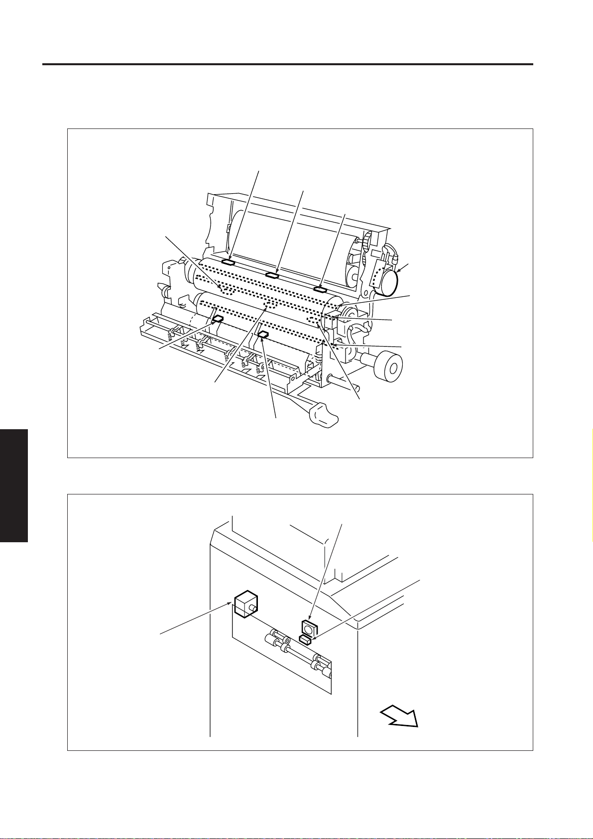
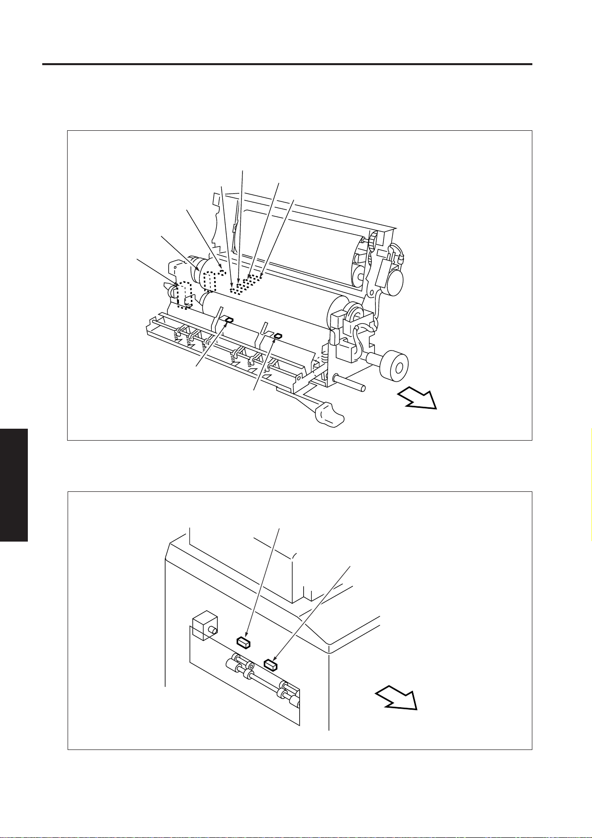
[10] Fixing Unit
TH4
Fixing temperature
sensor 4
PS3
Fixing jam PS
TH2
Fixing temperature sensor 2
TH1
Fixing temperature sensor 1
TS1
Thermostat (upper)
M16
Web drive motor
L2
Fixing heater lamp 1
L3
Fixing heater lamp 2
L4
Fixing heater lamp 3
[11] Paper Exit Section
ELECTRIC PARTS LIST
4
M10
Paper exit motor
TH3
Fixing temperature
sensor 3
TS2
Thermostat 2 (lower)
PS2
Fixing exit PS
FM6
Main body cooling fan 3
PS61
Paper exit PS
4 - 6
FRONT
Page 8

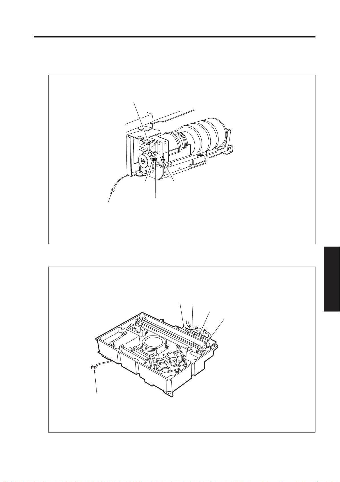
[12] Toner Supply Unit
M11
Toner supply motor 1
7075 PARTS LAYOUT DRAWING
[13] Write Section
PMDB
Polygon motor drive board
M15
Toner supply motor 2
INDXSB
Index sensor board
TLD
Toner level detection sensor
M17
Polygon motor
M24
Laser correction motor
ELECTRIC PARTS LIST
4
LDB1
Laser driver board 1
4 - 7
LDB2
Laser driver board 2
Page 9

7075 PARTS LAYOUT DRAWING
[14] Control/Drive Unit in Rear Section
SCDB
Scanner drive board
M2
Drum motor
M3
Developing motor
HV1
High voltage unit 1
FM2
Developing section fan
M1
Main motor
KRDS
KRDS board
M13
Scanner drive motor
KRDS
LAN IFB
LAN I/F board
FM4
Main unit cooling
fan 2
FM3
Main unit cooling
fan 1
M6
Loop roller
motor
PSMB
Power
supply
management
ELECTRIC PARTS LIST
board
4
DCDB
DC drive board
DCPS1
DC power
supply unit 1
M4
Paper feed
motor
PRCB
Printer control
board
DCPS2
DC power
supply unit 2
RL1
Main relay
RL3
AC input relay for IP
CBR1
Circuit
breaker 1
M10
Paper exit motor
CBR2
Circuit breaker 2
TRC1
Triac 1
TRC2
Triac 2
ACDB
AC drive board
Transformer
NF
Noise filter
RL2
AC input relay for DCPS2
4 - 8
Page 10
OPTIONAL PARTS LAYOUT DRAWING
DF-313 ELECTRICAL PARTS LAYOUT DRAWING
PS301
RADF open/close detection PS
SD303
Original exit gate SD
SD301
Flapper drive SD
M303
Tray up/down drive motor
M302
DFCB
RADF
control board
M305
Original exit motor 2
Original feed motor
M304
Original exit motor 1
PS313
Original exit reverse detection PS
PS302
Original size detection PS1
PS303
Original size detection PS2
PTBD
Tray board
MS301
Cover open/close MS
SD304
SDF switching SD
VR301
Original size
detection VR
PS314
Original exit PS2
PS310
Original count detection PS
SD302
Pressure roller release SD
PS316
Tray lower limit detection PS
FM301
ADF fan
PS317
APS timing PS
PS304
Reverse jam detection PS
PS309
Original reversal detection PS
PS315
Tray upper limit detection PS
PS305
No original detection PS
M301
Original conveyance motor
PS311
Original skew
detection PS 1
PS308
Original conveyance
detection PS
PS312
Original skew
detection PS2
ELECTRIC PARTS LIST
4
PS307
Original exit PS1
PS306
Original registration
detection PS
4 - 9
Page 11
OPTIONAL PARTS LAYOUT DRAWING
LT-401 ELECTRICAL PARTS LAYOUT DRAWING
SW100
LT tray down drive switch
PS108
LT No paper detection PS
PS107
LT pre-registration PS
MS102
LT top cover interlock MS2
PS100
LT top cover open/
close detection PS
MC101
LT feed drive MC
M100
LT up/down motor
PS102
LT remaining
paper detection PS1
PS103
LT remaining
paper detection PS2
PS104
LT remaining
paper detection PS3
PS105
LT remaining paper detection PS4
MS101
LT top cover interlock MS1
PS110
LT jam access door
open/close detection PS
SD100
LT 1st paper feed SD
PS109
LT upper limit detection PS
PS106
LT feed PS
MC102
LT 1st paper feed MC
M101
LT paper feed motor
LTDB
LT drive board
HTR101
LT internal heater
PS101
LT lower limit detection PS
ELECTRIC PARTS LIST
4
4 - 10
Page 12

7075 CONNECTOR LAYOUT DRAWING
7075 CONNECTOR LAYOUT DRAWING
[1] Read Section
651 (W: 3pin)
640 (BK:4pin)
665 (W: 3pin)
666 (W: 3pin)
650 (W: 3pin)
652 (W: 3pin)
653 (W: 3pin)
660 (W: 3pin)
661 (W: 3pin)
662 (W: 3pin)
663 (W: 3pin)
664 (W: 3pin)
FRONT
[2] Charging Corona Wire Unit
356 (W: 2pin)
631 (BK:4pin)
353 (W: 11pin)
ELECTRIC PARTS LIST
4
357 (W: 3pin)
358 (W: 3pin)
359 (W: 3pin)
4 - 11
FRONT
Page 13
7075 CONNECTOR LAYOUT DRAWING
[3] Drum Unit
342 (W: 2pin)
341 (BK: 26pin)
[4] Cleaning Unit
350 (W: 4pin)
353 (W: 7pin)
340 (B: 12pin)
351 (W: 4pin)
341 (BK: 10pin)
ELECTRIC PARTS LIST
4
361 (W: 3pin)
360 (W: 3pin)
355 (BK: 9pin)
4 - 12
Page 14
[5] Tray 1,2,3
7075 CONNECTOR LAYOUT DRAWING
250, 252 (BK: 24pin)
269, 307 (W: 2pin)
271, 288 (W: 3pin)
270, 287 (W: 3pin)
268, 252 (W: 3pin)
261, 278 (W: 2pin)
260, 277 (W: 2pin)
255, 283 (W: 3pin)
262, 279 (W: 6pin)
275 (W: 3pin)
276 (W: 3pin)
274 (W: 3pin)
273 (W: 3pin)
263, 280 (W:6pin)
264 (W: 2pin)
277, 289
(W:2pin)
265, 282 (W: 3pin)
FRONT
267, 285 (BK: 2pin)
[6] Vertical Conveyance Section
292 (W: 3pin)
293 (W: 3pin)
295 (W: 3pin)
254 (W: 12pin)
253 (W: 10pin)
294 (W: 3pin)
750 (W: 10pin)
ELECTRIC PARTS LIST
4
FRONT
296 (W: 3pin)
4 - 13
Page 15
7075 CONNECTOR LAYOUT DRAWING
[7] By-pass Feed Section
471 (BK:9pin)
77 (BK:4pin)
76 (BK:4pin)
473 (W:13pin)
[8] Second Paper Feed Section
246 (W:3pin)
247 (W:2pin)
470 (W:13pin)
254 (W:12pin)
248 (W:2pin)
254 (W:7pin)
244 (W:3pin)
243 (W:3pin)
242 (W:3pin)
241 (W:3pin)
ELECTRIC PARTS LIST
4
599 (W: 3pin)
570 (W: 3pin)
598 (W: 3pin)
591 (W: 10pin)
569 (W: 7pin)
568 (W: 8pin)
565 (W: 2pin)
FRONT
4 - 14
Page 16
[9] ADU Unit
7075 CONNECTOR LAYOUT DRAWING
557 (W: 6pin)
565 (W: 3pin)
569 (W: 7pin)
568 (W: 8pin)
592 (W: 3pin)
578 (W: 3pin)
678 (W: 6pin)
593 (W: 2pin)
581 (W: 3pin)
580 (W: 3pin)
586 (W: 3pin)
583 (W: 3pin)
588 (W: 3pin)
584 (W: 3pin)
531 (W: 7pin)
587 (W: 3pin)
585 (W: 3pin)
557 (W: 6pin)
577 (W: 3pin)
564 (W: 2pin)
580 (W: 5pin)
561 (W: 2pin)
ELECTRIC PARTS LIST
4
525 (W: 2pin)
562 (W: 2pin)
569 (W: 6pin)
FRONT
4 - 15
Page 17
7075 CONNECTOR LAYOUT DRAWING
[10] Fixing Unit
489 (W: 5pin)
462 (W: 2pin)
451 (BK: 20pin)
450 (B: 8pin)
488 (W: 4pin)
487 (W: 3pin)
486 (W: 2pin)
[11] Paper Exit Section
ELECTRIC PARTS LIST
4
465 (W: 3pin)
464 (W: 3pin)
FRONT
177 (W: 3pin)
480 (W: 3pin)
4 - 16
FRONT
Page 18
[12] Toner Supply Unit
7075 CONNECTOR LAYOUT DRAWING
482 (W: 6pin)
[13] Write Section
184 (W: 4pin)
473 (W: 13pin)
483 (W: 3pin)
193 (W: 6pin)
484 (W: 3pin)
192 (W: 13pin)
190 (W: 12pin)
191 (W: 14pin)
ELECTRIC PARTS LIST
4
583 (W: 5pin)
4 - 17
Page 19
7075 CONNECTOR LAYOUT DRAWING
[14] Printer Control Board
224 (W: 7pin)
291 (N.C.)
230 (W: 3pin)
222 (W: 15pin)
228 (W: 8pin)
227 (W: 9pin)
211 (GY: 60pin)
271 (GY:16pin)
220 (GY: 50pin)
292 (N.C.)
295 (N.C.) 200 (W: 5pin)
290 (N.C.)
[15] Power Supply Management Board
225 (GY: 20pin)
37 (N.C.)
298 (N.C.)
[16] Image Control Board
229 (W: 5pin)
216 (W: 15pin)
218 (W: 12pin)
223 (GY: 20pin)
215 (GY: 18pin)
210 (GY: 30pin)
213 (GY: 60pin)
299 (N.C.)
904 (W: 5pin)
ELECTRIC PARTS LIST
4
900 (W: 8pin)
902 (W: 3pin)
901
(W: 18pin)
903 (W: 4pin)
117 (BK: 168pin)
116 (BK: 168pin)
115 (BK: 168pin)
113 (BK: 120pin)
111 (GY: 8pin)
114 (BK: 168pin)
110 (GY: 34pin)
118 (W: 20pin)
112 (BK: 120pin)
128 (BN: 20pin)
129 (BN: 40pin)
119 (W: 3pin)
120 (BK: 60pin)
4 - 18
Page 20
[17] ICB I/F Board
101 (W: 3pin)
7075 CONNECTOR LAYOUT DRAWING
127 (BK: 120pin)
100 (W: 10pin)
134 (BK: 20pin)
133 (W: 8pin)
132 (W: 13pin)
131 (W: 14pin)
130 (W: 12pin)
[18] ADU Stand Drive Board
500 (W: 8pin)
140 (W: 9pin)
139 (W: 8pin)
135 (GY: 22pin)
137 (GY: 20pin)
138 (W: 13pin)
523 (W: 6pin)527 (W: 7pin)528 (W: 8pin)524 (W: 6pin)
145 (N.C.)
ELECTRIC PARTS LIST
4
501 (W: 2pin)
510 (W: 11pin)
525 (W: 12pin)
526 (W: 10pin)
591 (N.C.)
593 (N.C.)
4 - 19
594 (N.C.)
520 (GY: 28pin)
521 (GY: 16pin)
522 (W: 12pin)
Page 21
7075 CONNECTOR LAYOUT DRAWING
[19] DC Drive Board
301 (W: 2pin)
325
(W: 6pin)
F2
300 (W: 6pin)
Caution: Must use fuses specified by Konica
324 (W: 6pin)
F1
321 (W: 7pin)
323 (W: 7pin)
320 (W: 14pin)
when replacing F1 and F2. If fuses
are not specified by Konica, the
safety feature may not work,
resulting in burn damage to the
board or personal injury.
322
(W: 12pin)
310
(GY: 60pin)
[21] DC Power Supply Unit 1
60 (W: 6pin)
57 (W: 8pin)
58 (W: 8pin)
55 (W: 10pin)
59 (W: 4pin)
54 (W: 5pin)
52 (W: 5pin)
56 (W: 10pin)
53 (W: 7pin)
1 (W: 2pin)
[22] DC Power Supply Unit 2
51 (W: 4pin)
2 (W: 2pin)
Parts specified by Konica
Part Part number
F1 963003200
F2 963003000
[20] AC Drive Board
ELECTRIC PARTS LIST
4
35 (W: 5pin)
420 (GY: 18pin)
36 (N.C.)
410 (GY: 60pin)
400 (W: 8pin)
424 (W: 2pin)
401 (W: 2pin)
FT1 (W: 1pin)
FT3 (W: 1pin)
FT2 (W: 1pin)
FT4 (W: 1pin)
430 (W: 4pin)
440 (W: 5pin)
422 (W: 6pin)
442 (W: 5pin)
71 (W: 7pin)
72 (W: 8pin)
73 (W: 8pin)
74 (W: 10pin)
76 (W: 9pin)
75 (W: 4pin)
FT4 (W: 1pin)
FT1 (W: 1pin)
FT2 (W: 1pin)
FT3 (W: 1pin)
4 - 20
Page 22

7075 CONNECTOR LAYOUT DRAWING
[23] Scanner Drive Board
620 (W: 3pin)
623 (W: 7pin)
622 (W: 4pin)
621 (W: 4pin)
610 (W: 15pin)
600 (W: 6pin)
[24] High Voltage Unit 1
[26] Jam Indicator Board
531 (W:7pin)
[27] L1 Inverter
251 (W:9pin)
[25] High Voltage Unit 2
551 (W:11pin)
250 (W:3pin)
550 (W:4pin)
632 (W: 3pin) 2 (W: 2pin)
[28] Drum Potential Sensor Board
457 (W: 5pin)
458 (W: 4pin)
ELECTRIC PARTS LIST
4
4 - 21
Page 23
7075 CONNECTOR LAYOUT DRAWING
[29] Drum Temperature Sensor Board
455 (W: 4pin)
456 (BK: 2pin)
[30] Operation Board 1
161 (BK: 14pin)
[32] Optional I/F Board
123 (W: 120pin)
122 (BK: 60pin)
124 (W: 120pin)
[33] OB Inverter
165 (W: 3pin)
152
ELECTRIC PARTS LIST
4
[31] Operation Board 2
163 (W: 3pin)
164 (BK: 24pin) 151 (W: 7pin)
162 (W: 4pin)
150 (W: 10pin)
153 (W: 3pin)
160 (BK: 24pin)
166 (W: 4pin)
[34] Toner Control Sensor Board
454 (W: 9pin)
4 - 22
Page 24

7075 CONNECTOR LAYOUT DRAWING
[35] KRDS
219 (W: 11pin)
217 (BK: 25pin)
[36] Index Sensor Board
[39] Polygon Motor Drive Board
130 (W: 5pin)
422 (W: 12pin)
[40] Memory Board
141 (W: 20pin)
442 (W: 11pin)
[37] A/D Converter Board
410 (W: 5pin)
411 (W: 34pin)
[38] Laser Driver Board 1/2
142 (W: 20pin)
[41] LAN I/F Board
144
(W: 8pin)
ELECTRIC PARTS LIST
4
145 (W: 8pin)
440 (W: 12pin)
4 - 23
Page 25

OPTION CONNECTOR LAYOUT DRAWING
DF-313 CONNECTOR LAYOUT DRAWING
4 (W: 7pin)
3 (W: 8pin)
1 (W: 4pin)
16 (W: 3pin)
15 (W: 6pin)
ELECTRIC PARTS LIST
4
49 (W: 3pin)
6 (W: 6pin)
5 (W: 3pin)
14 (W: 6pin)
13 (W: 6pin)
57 (W: 2pin)
7 (W: 9pin)
12 (W: 7pin)
59 (W: 2pin)
8 (GY: 24pin)
64/65 (W: 3pin)
54 (W: 6pin)
61 (W: 2pin)
66 (W: 2pin)
41 (W: 3pin)
10 (W: 6pin)
11 (W: 6pin)
11 (W: 6pin)
51 (W: 3pin)
50 (W: 3pin)
52 (W: 3pin)
53 (W: 3pin)
54/55 (W: 6pin)
35 (W: 3pin)
22 (W: 9pin)
21 (W: 6pin)
34 (W: 3pin)
23 (W: 3pin)
4 - 24
44 (W: 3pin)
45 (W: 3pin)
48 (W: 3pin)
38 (W: 3pin)
39 (W: 3pin)
37 (W: 3pin)
41 (W: 3pin)
Page 26

OPTION CONNECTOR LAYOUT DRAWING
LT-401 CONNECTOR LAYOUT DRAWING
744 (W: 3pin)
742 (W: 3pin)
741 (W: 3pin)
766 (W: 2pin)
784 (W: 2pin)
747 (W: 3pin)
746 (W: 3pin)
765 (W: 2pin)
774 (W: 2pin)
762 (W: 3pin)
749 (W: 3pin)
780 (B: 3pin)
781 (W: 3pin)
783 (W: 3pin)
782 (B: 3pin)
Caution: Must use fuses specified by
Konica when replacing F1. If
fuse is not specified by Konica,
the safety feature may not work,
resulting in burn damage to the
board or personal injury.
745 (W: 3pin)
761 (W: 2pin)
767 (W: 2pin)
773 (W: 3pin)
740 (W: 3pin)
773 (W: 2pin)
771 (W: 2pin)
751 (W: 6pin)
750 (W: 10pin)
720 (W: 5pin)
F1
723 (W: 8pin)
721
(W: 8pin)
722
(GY: 20pin)
ELECTRIC PARTS LIST
4
Parts specified by Konica
Part Part number
F1 963003200
700 (W: 4pin) 710 (GY: 18pin)
4 - 25
Page 27

7075 OVERALL WIRING DIAGRAM (1/5)
CBR1
BK BK
NF
FORMER
751-5
GY
18
305-5
GY
17
305-3
GY
16
305-1
GY
15
TRANS
BK
12-1
90-1
10 11
BK
BK
BK BK
MAIN RELAY
W
4
W
506
12-4
90-2
1
MAIN SWITCH
13-1
RL1
SW1
20-1
BK BK
13-3
2
W
TRC1
504
TRC2
505
100V SYSTEM
BK
501
503
OUTLET
13-2
20-3
BK
RESET SWITCH
SW2
21-1
INLET
W
11-1
10-1
BK BK
21-2
13-4
BK
10-2
W
10-4
W
1
RL3
)
2-1 AC(H
10-3
BK
W
WW W
1
1-1 AC(H
2-2 AC(C
1-2 AC(C
)
)
)
53-1 5VDC
53-2 5VDC
53-3 5VDC
RBR
R
R
172-1
172-2
R
R
20
21
22
53-4 SGND
53-5 SGND
53-6 SGND
B
B
172-3
172-4
177-7
B
B
23
24
25
59-1 12VDC
BN
172-5
BN
27
ICB
59-2 5VDC
59-3 SGND
59-4 SGND
BBB
172-7
172-8
172-9
BBB
R
29
30
31
58-7 SGND
57-2 12VDC
BN
172-10
33
32
54-2 5VDC
54-4 SGND
B
B
R
34
35
36
PRCB
BK
W
W
BVYGYBRB
R
DCPS 1 DCPS 2
57-6 SGND
54-5 V DES
57-1 12VDC
54-1 5VDC
54-3 SGND
57-5 SGND
57-3 12VDC
55-1 5VDC
55-6 SGND
57-7 SGND
58-1 12VDC
56-1 5VDC
60-2 -5VDC
60-4 SGND
56-6 SGND
58-5 SGND
56-3 5VDC
56-8 SGND
55-2 5VDC
55-7 SGND
57-4 12VDC
55-3 5VDC
55-8 SGND
55-4 5VDC
57-8 SGND
60-1 -5VDC
56-7 SGND
B
B
B
B
45
46
ACDB
BN
258-2
47
48
BBBRBRB
R
GY
258-3
258-4
258-5
258-6
258-7
49
50
51
52
ADUSDB
R
R
278-3
278-3
278-4
55
53
54
28
HDD
SCDB
R
GY
26
R
BN
BN
37
41
38
42
39
40
DCDB
BGYBRB
RBR
BN
472-4-5
472-3-6
472-2-7
472-1-8
472-5-4
177-5
177-4
177-3
B
RBR
BN
57
56
LT-401
61
58
62
60
63
72
74
OB
56-2 5VDC
58-5 SGND
58-2 12VDC
BN
177-2
177-1
755-2
66
64
65
ADB
5VDC 52-1
56-5 5VDC
56-10 SGND
60-5 SGND
B
BRB
R
755-3
755-6
89
67
77
FNS
SGND 52-2
56-4 5VDC
56-8 SGND
758-3
758-4
70
DF-313
REM/2 52-3
REM/1 52-4
SW SIG 52-5
SGND 51-1
F GND BT1
58-3 12VDC
BN
342-3
68
PRCB
Y
5VDC 51-2
SGND 51-3
REM/2 51-4
RL2
10-5
PT-3 AC(H
)
SGND 71-1
10-6
PT-4 AC(C
)
72-1 24VDC
O
78 79 80
DCDB
O
5VDC 71-2
SGND 71-3
REM/2 71-4
REM/3 71-5
CUR EM 71-6
NC 71-7
72-5 PGND
72-2 24VDC
72-6 PGND
73-1 24VDC
73-5 PGND
72-4 24VDC
72-8 PGND
73-2 24VDC
73-6 PGND
72-3 24VDC
73-6 PGND
73-3 24VDC
OBKOBKOBKOBKOBKOBKOBKOBKO
BK
258-1
258-8
342-1
342-2
81 82 83 84 85 86 87 88 89 90 91 92 93 94 95 96 97
M4
ACDB
ADUSDB
LT-401
PMDB
DPSB
72-7 PGND
73-4 24VDC
73-8 PGND
HDD
74-1 24VDC
74-7 PGND
278-1
278-5
278-2
74-2 24V2
74-8 PGND
74-10 PGND
75-1 24VDC
75-3 PGND
74-9 PGND
75-2 24VDC
75-4 PGND
BK
BKOBK
BKOBK
278-6
278-7
755-1
755-4
755-5
758-1
758-2
100
112 102 103 104 105 106 107 108 109 110 111
98 99
FNS
SCANNER
DF-313
24VDC FT1
24VDC FT2
F GND BT1
76-1 PGND
76-2 PGND
76-3 PGND
76-4 PGND
76-5 PGND
76-6 PGND
BKBKBKBKBKBKBK
M3M2M1
HV1
M15
DCDB
76-8 PGND
76-7 PGND
BK
ACDB
ADUSDB
MS2 MS1
80-1
BK
80-2
BK
81-1
81-2
81-3
81-4
81-5
OOOOOOO
113 114 115 116 117 118 119 120
M3M2M1
HV1
M15
650
651
652
653
654
655
656
80-3
BK
80-4
BK
82-1
82-3
82-2
O
ACDB
DCDB
ADUSDB
4
5
657
658
659
200V SYSTEM
510
509
BN
R
B
B
B
R
R
B
B
TRC1
TRC2
CBR2
100-5 12VDC
100-7 5VDC
100-8 SGND
100-9 SGND
100-10 SGND
100-1 5VDC
100-2 5VDC
100-3 SGND
100-4 SGND
504
505
501
503
503
502
508
APS
SENSOR
PS62
665-3
R
163-9-1
174-1-12
RBNB
5VDC 137-A1
RL3
1
OUTLET
W
3
5
SCANNER
APS
APS
APS
SENSOR
SENSOR
1
2
SENSOR
3
APS
SENSOR
4
5
PS63 PS64 PS65 PS66 PS67 PS68
665-2
665-1
666-3
666-2
666-1
662-3
662-2
662-1
664-3
664-2
664-1
661-3
661-2
661-1
R
R
R
B
B
163-7-3
163-8-2
163-6-4
174-3-10
174-2-11
174-4-9
Y
H
H
PS62 137-A3
PS63 137-A4
137-A2
B
163-5-5
174-5-8
V
H
PS64 137-A5
B
163-4-6
174-6-7
GY
H
PS65 137-A6
R
B
163-3-7
174-7-6
w
H
PS66 137-A7
APS
SENSOR
6
663-3
663-2
R
163-2-8
174-8-5
BK
PS67 137-A8
166-1
166-2
166-3
166-4
OB INVB
165-1
165-2
164-1
164-24
163-1
163-2
OB2
165-3
163-3
L
475-1
GY
475-5
BN
BN
57
475-6
R
R
475-4
B
58
B
60
475-3
Y
475-2
V
LCD
APS
SENSOR
7
161-1
161-14
162-1
161-4
P
160-24
157-5-5
157-4-6
157-3-7
157-2-8
157-1-9
GY
GY
GY
GY
P
CARD TXD 140-9
OB1 RXD ACK 140-4
OB1 TXD REQ 140-5
140-6
140-7
140-8
160-1
442-6
442-7
442-8
442-9
442-10
442-11
442-12
WRITING
442-1
442-13
442-2
442-3
442-4
442-5
442-6
442-7
442-8
442-9
442-10
OB1
442-1
442-2
442-3
442-4
442-5
442-6
442-7
442-8
442-9
442-10
442-11
442-11
442-12
442-12
663-1
660-3
660-2
660-1
R
B
B
LASER
CORRECTION
MOTOR
M24
INDEXSB LDB1 LDB2
442-1
442-2
442-3
442-4
442-5
RCRCRC
136-1-9
195-1
195-2
O
BN
H
PS68 137-A9
O
193-6-1
193-5-2
BN
PPPPP
NC 137-A10
M24 PWR A 133-1
M24 PWR B 133-2
174-9-4
H
195-3
193-4-3
BN
M24 DRIVE A 133-3
195-4
Y
193-3-4
Y
M24 DRIVE A’ 133-4
195-5
193-2-5
V
BOR
M24 DRIVE B 133-5
195-6
GY
193-1-6
GY
w
P
H
H
HLVL 133-7
SMPR 133-8
M24 DRIVE B’ 133-6
194-1
194-2
194-3
194-4
194-5
Y
O
R
BN
192-13-1
192-12-2
192-11-3
192-10-4
192-9-5
GY
GY
GY
GY
P
5VDC 132-1
SGND 132-2
SGND 132-4
M INDEX 1 132-3
194-6
194-7
194-8
194-9
B
V
W
GY
192-8-6
192-7-7
192-6-8
192-5-9
GYGYGY
GY
SGND 132-6
SGND 132-8
S INDEX 1 132-7
M INDEX 2 132-5
194-10
194-11
194-12
194-13
R
O
BK
BN
192-4-10
192-3-11
192-2-12
192-1-13
GY
GY
GY
GY
PPP
H
1PR 132-12
SGND 132-10
HL VL 132-11
S INDEX 2 132-9
Y
191-14-1
191-12-3
191-13-2
GY
GY
GY
5VDC 131-1
SGND 132-13
SGND 131-2
GY
LD1 APC CONT 1 131-3
191-11-4
191-10-5
GY
LD1 APC CONT 2 131-4
191-9-6
191-8-7
191-7-8
191-6-9
GYGYGY
GY
P
H
H
SGND 131-6
LD1 ALM 131-7
LD1 ICLK 131-8
LD1 VIDEO 131-5
GY
LD1 DCLK 131-9
191-5-10
GY
LD1 DI 131-10
191-4-11
191-3-12
GY
GY
LD1 AO 131-11
LD1 PR 131-12
190-12-1
190-11-2
GY
GY
NC 131-13
NC 131-14
5VDC 130-1
SGND 130-2
190-10-3
GY
LD1 APC CONT 1 130-3
190-9-4
GY
LD1 APC CONT 2 130-4
190-8-5
190-7-6
190-6-7
190-5-8
GYGYGY
GY
PHH
SGND 130-6
LD1 ALM 130-7
LD1 ICLK 130-8
LD1 VIDEO 130-5
190-4-9
GY
LD1 DCLK 130-9
190-3-10
GY
LD1 DI 130-10
190-2-11
190-1-12
GY
GY
LD1 AO 130-11
LD1 PR 130-12
ICB IFB - 1 / 2
72
60
475-8
RBR
475-7
B
153-1 5VDC
153-2 NC
154-3 CGND
PPP
157-9-1
157-8-2
157-7-3
157-6-4
GYGYGY
GY
GY
PPP
OB1 TXD 140-1
140-2
140-3
506
507
27
29
30
31
32
21
22
23
24
4 - 27
Page 28

7075 OVERALL WIRING DIAGRAM (2/5)
650
651
652
653
654
655
656
657
658
659
64
65
900-1 5VDC
900-2 SGND
900-6 REM/2
900-3 REM/1
R
20
900-5 5VDC
900-4 SW SIG
900-7 REM/3
900-8 CUREM
901-A1 WT LED
901-A2 ST LED
901-A3 ST SIG
901-A4 ALARM
901-A5 CPU OF
901-A6 IPRL CNT
VWY
R
O
GY
BN
472-3
472-2
472-1
197-5
350-5
GY
61
350-4
B
62
63
350-3
R
350-2
B
350-1
BN
197-4
197-3
197-2
197-1
410-5 -5VDC
410-4 SGND
410-3 5VDC
410-2 SGND
410-1 12VDC
901-A7 WT LON
Y
901-A8 ST LON
B
901-A9 SET CLK
901-B1 ST SIG
901-B2 RING
901-B3 SW SIG
V
GY
RC
411-1 TCK1
411-2 SGND
411-3 TCK2
411-4 SGND
PSMB
901-B4 24R CNT
901-B5 REM/2
901-B6 REM/3
R
O
BK
BN
411-5 RCK1
411-6 SGND
411-7 RCK2
901-B7 CUR EM
901-B8 N/C
901-B9 N/C
Y
411-8 SGND
411-9 TG
411-10 CLMP
411-11 S CK
411-12 S IN
411-13 S LD
176-4-4
140
ADB
411-14 MD 0
411-15 MD 1
411-16 MD 2
904-1 SGND
904-2 VDE REM
904-3 SGND
904-4 IP WEK
BYB
V
176-3-5
176-2-6
176-7-1
141
142
143
411-17 S LP
411-18 SGND
411-19 AD CK
411-20 APR
904-5 N/C
411-21 OD 0
5VDC 903-1
RL3 DRIVE 903-2
5VDC 903-3
RL2 DRIVE 903-4
411-22 OD 1
411-23 OD 2
411-24 OD 3
411-25 OD 4
176-1-7
411-26 OD 5
176-2-6
176-3-5
B
R
BN
5VDC 902-1
SGND 902-2
RING 902-3
L
L
411-27 OD 6
411-28 OD 7
411-29 OD 8
BK
BK
W
W
411-30 SGND
411-31 ED 0
411-32 ED 1
411-33 ED 2
RL3
RL2
KRDS
411-34 ED 3
LAN RB
175-1-13
175-2-12
175-3-11
175-4-10
175-5-9
175-6-8
175-7-7
175-8-6
175-9-5
175-10-4
175-11-3
GYGYGYGYGYGYGYGYGYGYGYGYGY
RING 138-8
ALARM 138-1
ST LON 138-5
CPU OF 138-2
WT LON 138-4
IPRL CNT 138-3
SET CLK 138-6
ST SIG 138-7
REM/2 138-11
SW SIG 138-9
24R CNT 138-10
ICB IFB - 2 / 2
175-12-2
175-13-1
REM/3 138-12
CUR EM 139-13
600
135-A1
B
BN
601
CN 112
CN 112
135-A2
135-A3
R
O
603
602
135-A4
PPPPPPPPP
135-A5
135-A6
135-A7 IPB IFB RXD
135-A8 SGND
135-A9 IPB IFB RXD REQ
135-A10 IPB IFB RXD ACK
135-A11 SGND
135-B1 IPB IFB RXD ERR
Y
BGNBVB
607
606
605
604
W
GY
611
610
609
608
135-B3 PVV
135-B4
135-B5 B VV
R
O
BN
614
613
612
135-B6 S VV
YGNV
615
616
110-1
110-2
110-3
135-B7 BYPAS SIZE
135-B8 EE VV
135-B9
GY
618
617
110-4
110-5
110-6
110-7
110-8
110-9
110-10
110-11
110-12
110-13
110-14
ICB
PPPPPPPPPPPPPPPPP
134-A1 HCLK
134-A2 DFD0
134-A3 DFD1
134-A4 DFD2
134-A5 DFD3
134-A6 DFD4
134-A7 DFD5
135-B10
W
619
134-A8 DFD6
ISW INTERFACE CONNECTER
RC
110-15
110-16
110-17
110-18
134-A9 DFD7
134-A10 PCLK
134-B1 PBUSY
110-19
110-20
110-21
110-22
110-23
134-B2 ADREQ
134-B3 XFLAG
134-B4 HBUSY
134-B5 DAVIL
134-B6 INT
110-24
110-25
110-26
110-27
110-28
134-B7 AC1284
134-B8 SGND
134-B9 SGND
134-B10 SGND
(FOR ISW TOOL)
110-29
110-30
110-31
110-32
101-1 5VDC
101-2 SGND
POWER
CONNECTER
110-33
110-34
DF TXD REQ 137-B2
DF TXD ACK 137-B3
DF RXD REQ 137-B5
DF RXD ACK 137-B6
PPPPPPP
139-1 5VDC
139-2 KRDS TXD
176-8-1
176-7-2
RC
OP IFB
CN 113 CN 113 CN 124
173-8-1
DF TXD 137-B1
P
P
P
DF RXD 137-B4
P
P
P
DF VALID 137-B7
P
PS315 137-B8
L
139-3 KRDS RTS
139-4 KDRS DTR
139-5 KDRS RXD
139-6 KDRS CRS
139-7 KDRS DSD
176-6-3
176-5-4
176-4-5
176-3-6
176-2-7
176-1-8
139-8 KDRS DSR
BN
173-7-2
R
173-6-3
O
173-5-4
Y
173-4-5
B
173-3-6
V
173-2-7
GY
173-1-8
W
CN 123
DF - 313
69
70
102
103
HDD IFB
IP IFB
SGND
140
141
4 - 28
VDB RBM
SGND
IP WEK
142
143
HDD
92
93
IP
28
25
Page 29

7075 OVERALL WIRING DIAGRAM (3/5)
SCANNER
EXPOSURE
LAMP
L1
LV
HV
M13 DRIVE W 620-3
610-5
610-6
INVB
832-1
832-2
BK
BK
831-1
831-2
O
830-1
830-2
O
H
24VDC 623-1
L1 CONT 623-2
610-7
610-8
610-9 FM7 EM
832-3
BK
831-3
831-4
830-3
NC 623-3
L
HHH
610-10 PS5
610-11 PS7
SCANNER
DRIVE
MOTOR
M13
100
96
53
54
95
97
601-7
601-1
O
94
601-2
601-3
601-4
601-5
601-6
O
R
B
B
B
600-3 24VDC
600-4 24VDC
600-1 5VDC
600-2 SGND
600-5 PGND
600-6 PGND
M13 DRIVE U 620-1
610-1
610-2
M13 DRIVE V 620-2
610-3
610-4
SCANNER
COOLING
FAN
FM7
640-1
640-2
640-4
B
L
PGND 621-3
FM7 EM 621-2
FM7 DRIVE 621-1
610-12 PS6
610-13 PS4
610-14 SCAN24V FEM
SCANNER
ADF
BRAKE
ORIGINAL
HP
HP
SENSOR
PS5 PS7 PS6 PS4
650-3
650-2
650-1
651-3
651-2
651-1
652-3
652-2
R
BRB
454-1
454-5
R
L
PS5 622-2
5VDC 622-1
B
SGND 622-3
H
PS7 622-4
R
5VDC 623-4
PS6 623-5
SCDB
610-15 SGND
H
652-1
454-7
SCANNER
B
SGND 623-6
RETURN
SENSOR
653-3
653-2
454-5
653-1
H
PS4 623-7
PAPER SIZE
SENSOR
1-1
PS32 PS33 PS26 PS48 PS20 PS47 PS14 PS34 VR1
270-1
270-2
270-3
R
BN
PAPER SIZE
B
SENSOR
2-1
271-1
271-2
RBY
271-3
NO PAPER
SENSOR 1
275-1
275-2
262-6-1
262-5-2
R
Y
REGISTRATION
SENSOR 1
275-3
262-4-3
B
PAPER
PRE-
276-3
262-3-4
R
276-2
262-2-5
BN
TRAY 1
276-1
262-1-6
B
TRAY
UPPER
LIMIT
SENSOR 1
274-1
274-2
263-3-4
263-2-5
R
TRAY 2 TRAY 3
PAPER
FEED
SENSOR 1
HANDLE
RELEASE
SENSOR 1
PAPER
DETECTION
SENSOR 1
PAPER
SIZE
DETECTION
VR 1
PAPER SIZE
SENSOR
1-2
PAPER SIZE
SENSOR
2-2
NO PAPER
SENSOR 2
PAPER
PRE-
REGISTRATION
SENSOR 2
TRAY
UPPER
LIMIT
SENSOR 2
PAPER
FEED
SENSOR 2
REMAINING
PS35 PS36 PS27 PS50 PS21 PS49 PS15 PS37 VR2
274-3
273-3
273-2
273-1
265-3
265-2
265-1
266-1
266-2
266-3
268-3
268-2
268-1
270-1
270-2
270-3
271-1
271-2
271-3
275-1
275-2
275-3
276-3
276-2
276-1
274-1
274-2
274-3
273-3
273-2
B
R
RBY
B
B
R
R
V
263-1-6
263-6-1
263-5-2
263-4-3
B
B
R
Y
BN
B
R
V
V
B
BN
R
262-6-1
R
262-5-2
Y
Y
262-4-3
B
R
262-3-4
R
BN
262-2-5
BN
B
262-1-6
B
R
263-3-4
R
BN
263-2-5
BN
B
263-1-6
B
R
263-6-1
R
Y
263-5-2
Y
273-1
B
263-4-3
B
HANDLE
RELEASE
SENSOR 2
265-3
265-2
R
V
265-1
B
REMAINING
PAPER
DETECTION
SENSOR 2
266-1
266-2
R
266-3
V
PAPER
DETECTION
268-3
B
SIZE
VR 2
R
PAPER SIZE
SENSOR
1-3
PAPER SIZE
SENSOR
2-3
NO PAPER
SENSOR 3
PAPER
PRE-
REGISTRATION
SENSOR 3
TRAY
UPPER
LIMIT
SENSOR 3
PAPER
FEED
SENSOR 3
PS38 PS39 PS28 PS52 PS22 PS51 PS16 PS40 VR3
268-2
268-1
287-1
287-2
287-3
288-1
288-2
288-3
275-1
275-2
275-3
276-3
276-2
276-1
274-1
274-2
274-3
273-3
273-2
280-2-5
BN
280-1-6
B
280-6-1
R
280-5-2
Y
273-1
280-4-3
B
R
RBY
B
V
B
BN
279-6-1
279-5-2
279-4-3
279-3-4
279-2-5
279-1-6
B
R
Y
280-3-4
B
R
R
BN
HANDLE
RELEASE
SENSOR 3
282-3
282-2
R
V
282-1
B
REMAINING
PAPER
DETECTION
SENSOR 3
283-1
283-2
R
V
DETECTION
283-3
B
PAPER
SIZE
VR 3
268-3
R
268-2
268-1
B
V
GY
GYGYGYGYGYGYGYGYGYGYGYGYGY
M13 V1 216-5
M13 V0 216-6
H
L1 CONT 216-7
L
FM7 CONT 216-8
216-9
216-10
216-11
P
M13 V2 216-4
M13 F/R 216-2
33
BN
CN200-1 12VDC
R
34
26
35
36
CN200-2 5VDC
GY
CN200-3 V_DES
B
CN200-4 SGND
B
CN200-5 SGND
M13 CLK 216-1
M13 CSEL 216-3
216-12
216-13
SCAN24V FEM 216-14
GY
SGND 216-15
250-12
250-14
250-11
250-23
Y
R
W
B
H
PS32 220-A3
5VDC 220-A2
SGND 220-A4
TRAY 1 SET 220-A1
250-15
Y
PS33 220-A6
250-19
Y
H
PS26 220-A10
250-21
GY
H
PS48 220-A13
250-17
GY
H
PS20 220-A8
250-22
BK
H
PS47 220-A14
250-16
V
H
PS14 220-A7
250-18
250-10
250-20
R
V
BK
L
PS34 220-A9
5VDC 220-A11
251-12
251-14
W
H
VR1 220-A12
TRAY 2 SET 220-A17
251-11
251-23
251-15
Y
R
B
PS35 220-A19
5VDC 220-A18
SGND 220-A20
251-19
Y
Y
H
PS36 220-A22
PS27 220-B1
251-21
GY
H
PS50 220-B4
251-17
GY
H
PS21 220-A24
251-22
BK
H
PS49 220-B5
251-16
V
H
PS15 220-A23
251-18
251-10
251-20
R
V
BK
L
VR2 220-B3
PS37 220-A25
5VDC 220-B2
252-12
252-14
252-11
252-23
Y
R
W
B
H
PS38 220-B13
5VDC 220-B12
SGND 220-B14
TRAY 3 SET 220-B11
252-15
Y
NC 220-B15
PS39 220-B16
252-19
Y
H
PS28 220-B20
252-21
GY
H
PS52 220-B23
252-17
GY
H
PS22 220-B18
252-22
BK
H
PS51 220-B24
252-16
252-18
V
H
PS16 220-B17
252-10
252-20
R
V
BK
L
VR3 220-B22
PS40 220-B19
5VDC 220-B21
PRCB - 1 / 3
H
228-4 M15 CONT
228-5 M15 EM
108
BNVBK
470-9-5
470-8-6
470-7-7
GY
473-5-9
473-6-8
473-7-7
Y
W
BK
184-2
184-3
184-4
H
228-6 M3 CONT
114
Y
O
182-1
182-2
DEVELOPING
MOTOR
H
HHHHH
211-A1
211-A2 M19 CONT
211-A3
211-A4
211-A5 MC4 CONT
211-A6 SD5 CONT
211-A7 MC3 CONT
211-A8 SD8 CONT
78
O
300-1 24VDC
BN
37
38
39
40
79
118
109
R
B
B
BK
O
BK
300-2 12VDC
300-3 5VDC
300-4 SGND
300-5 SGND
300-6 PGND
301-1 24VDC
301-2 PGND
H
320-1 24VDC
320-2 M19 CONT
OBKOYV
250-3
250-4
250-5
O
O
BK
O
264-1
264-2
260-1-2
M19
MC3 MC4 SD8 SD5
UP
FEED
DRIVE
CLUTCH 1
MOTOR 1
H
H
320-3 24VDC
320-4 MC3 CONT
320-5 MC4 CONT
250-6
250-7
V
Y
O
260-2-1
261-1-2
261-2-1
SOLENOID 1
PRE-
REGISTRATION
CLUTCH 1
O
272-1-2
PICK-
UP
250-8
272-2-1
H
320-6 SD8 CONT
GY
BN
H
310-A2
12V_F 310-A1
H
320-7 SD5 CONT
Y
250-9
Y
O
267-1
267-2
LOCK
SOLENOID 1
M19 EM 310-A3
L
M19 FEM 310-A4
310-A5
310-A6
310-A7
H
320-8 24VDC
320-9 M20 CONT
OBKOYV
251-3
251-4
O
BK
264-1
264-2
M20
UP
DRIVE
CLUTCH 2
MOTOR 2
310-A8
TRAY 1 TRAY 2 TRAY 3 BY-PASS DRUMVERTICAL
HHHHH
211-A9 M20 CONT
211-A10
211-A11
211-A12 MC6 CONT
211-A13 SD6 CONT
211-A14 MC5 CONT
L
310-A9
310-A12
310-A13
310-A14
M20 EM 310-A10
M20 FEM 310-A11
H
H
H
320-10 24VDC
320-11 MC5 CONT
320-12 MC6 CONT
320-13 SD9 CONT
GY
251-5
251-6
251-7
251-8
V
O
260-1-2
Y
260-2-1
O
261-1-2
261-2-1
O
272-1-2
BN
272-2-1
MC5 MC6 SD9 SD6
FEED
PRE-
REGISTRATION
CLUTCH 2
PICK-
UP
SOLENOID 2
SOLENOID 2
211-A15 SD9 CONT
211-A16 M21 CONT
310-A15
310-A16
H
320-14 SD6 CONT
Y
251-9
Y
O
267-1
267-2
LOCK
211-A17
M21 EM 310-A17
211-A18
L
M21 FEM 310-A18
HHH
H
211-A19 MC8 CONT
211-A20 SD7 CONT
211-A21 MC7 CONT
211-A22 SD10 CONT
310-A19
310-A20
310-A21
310-A22
H
321-1 24VDC
321-2 M21 CONT
OBKOYV
252-3
252-4
252-5
281-1
281-2
277-1-2
M21
MC7 MC8 SD10 SD7
UP
FEED
DRIVE
CLUTCH 3
MOTOR 3
211-A23 M22 TR1
211-A24 M22 TR2
211-A25 M22 TR3
310-A23
310-A24
310-A25
H
H
321-3 24VDC
321-4 MC7 CONT
321-5 MC8 CONT
252-6
252-7
277-2-1
278-1-2
278-2-1
SOLENOID 3
PRE-
REGISTRATION
CLUTCH 3
211-A26 M22 TR4
211-A27
L
310-A26
M22 FEM 310-A27
H
321-6 SD10 CONT
GY
252-8
289-1-2
289-2-1
PICK-
UP
SOLENOID 3
HHH
211-A28 SD11 CONT
211-A29 MC9/10 CONT
310-A28
310-A29
H
321-7 SD7 CONT
Y
252-9
285-1
285-2
LOCK
211-A30 M23 CONT
211-B1 M23 F/R
310-A30
311-B1
211-B2
M23 EM 311-B2
211-B3 M14 PL
211-B4 M14 NL
311-B3
322-1 M22 DRIVE 1
BN
254-1-12
247-1
M22
UP/DOWN
MOTOR
(BY-PASS)
211-B5 M14 PR
211-B6 M14 NR
211-B7
211-B8
311-B5
311-B6
M14 CEM 311-B7
L
M14 24FEM 311-B8
311-B4
H
322-2 M22 DRIVE 2
322-3 24VDC
322-4 SD11 CONT
322-5
V
O
BN
254-2-11
254-3-10
254-4-9
247-2
248-2-1
248-1-2
SD11 MC9 MC10
PICK-
UP
SOLENOID
(BY-PASS)
H
H
211-B9 SD4 CONT
211-B10 PCL CONT
311-B9
311-B10
H
322-6 24VDC
322-7 MC9 CONT
Y
O
253-1-10
253-2-9
YOV
OO
290-1-2
290-2-1
VERTICAL
CONVEYANCE
CLUTCH 1
PAPER
FEED
211-B11
211-B12
24VDC 311-B11
24VDC 311-B12
H
322-8 M10 CONT
BN
253-3-8
291-1-2
291-2-1
VERTICAL
CONVEYANCE
CLUTCH 2
211-B13
5VDC 311-B13
P
211-B14 M11 CLK
211-B15
311-B14
SGND 311-B15
323-1 M14 DRIVE 1
O
341-15
O
355-1
M14
CLEANING
BLADE
MOTOR
P
211-B16 M11 VREF
211-B17
211-B18 M6 CLK
L
311-B16
M11 FEM 311-B17
323-2 M14 DRIVE 2
323-6 M23 DRIVE 1
R
BK
341-17
341-18
341-16
341-24
B
R
BK
353-3-9
353-2-10
355-2
B
R
359-1
359-3
M23
CHARGER
CLEANING
MOTOR
211-B19 SGND
211-B20 M6 F/R
311-B18
311-B19
311-B20
323-7 M23 DRIVE 2
B
B
BK
353-1-11
BK
359-2
L
211-B21 M11 RES
211-B22 M6 OFF
311-B21
311-B22
323-3 24VDC
O
341-12
341-13
O
354-1
354-2
SD4
SEPARATION
CLAW
SOLENOID
211-B23 M6 VREF
211-B24
L
311-B23
M6 24FEM 311-B24
H
323-4 SD4 CONT
V
O
V
353-11-1
356-1-2
PCL
PCL
H
323-5 PCL CONT
BK
341-14
BKBKOBK
353-10-2
356-2-1
211-B25
FM5 EM 311-B25
12
340-2
352-1
355-9
L
L
211-B26 FM5 CONT
211-B27 FM5 H/L
311-B26
311-B27
13
340-3
W
352-2
HTR1
211-B28
211-B29
211-B30
L
SGND 311-B30
24VDC 311-B29
FM5 FEM 311-B28
PPPPPPP
324-1 24VDC
324-2 24VDC
324-3 M11 DRIVE A
OOV
470-6-8
470-5-9
470-4-10
GYGYGYGYGY
473-8-6
473-9-5
473-10-4
OOYBNV
482-1-6
482-2-5
482-3-4
M11 M6
TONER
SUPPLY
MOTOR 1
324-4 M11 DRIVE A
324-5 M11 DRIVE B
YBNV
470-3-11
470-2-12
473-11-3
473-12-2
W
482-4-3
482-5-2
324-6 M11 DRIVE B
325-1 24VDC
325-2 24VDC
470-1-13
GY
473-13-1
482-6-1
LOOP
ROLLER
MOTOR
DCDB
P
325-3 M6 DRIVE A
325-4 M6 DRIVE A
325-5 M6 DRIVE B
325-6 M6 DRIVE B
L
L
322-9 FM5/FM8 DRIVE
322-10 FM5/FM8 H/L
322-11 FM5 EM
322-12 PGND
O
Y
BN
BK
471-6
471-8
471-7
471-9
76-1
76-3
76-2
76-4
FM5
WRITE
SECTION
COOLING
FAN 1
77-1
77-2
FM8
WRITE
SECTION
COOLING
FAN 2
77-3
L
228-1 TLD CONT
228-2 TLD
228-3 SGND
V
R
B
117
O
470-13-1
470-12-2
470-11-3
470-10-4
GYGYGY
GYGYGY
473-1-13
473-2-12
473-3-11
V
R
B
473-4-10
O
483-3-1
483-2-2
483-1-3
GYGYGY
184-1
484-1
484-2
484-3
M15
TLD
TONER
TONER
SUPPLY
LEVEL
MOTOR 2
DETECTION
SENSOR
77-4
P
228-7 M3 CLK
228-8 M3 EM
116 107
105
BNVBKOBNVBK
182-3
182-4
182-5
181-1
181-2
M3
MAIN
MOTOR
H
229-1 M1 CONT
229-2 M1 EM
181-3
181-4
M1
2-1 SGND
2-2 24VDC
P
230-1
230-2 M17 CLK
86
Y
O
BN
474-1
474-2
474-3
474-4
583-5
583-1
583-2
583-3
O
Y
BK
130-5
130-2
M17 EM 130-1
2-3 M17 MAG A’
2-4 M17 MAG A
2-5 M17 MAG B’
2-6 M17 MAG B
M17
POLYGON
MOTOR
H
230-3 M17 CONT
87
V
BK
474-5
583-4
V
BN
130-3
130-4
PMDB
PPP
2-7 M17 MAG C’
2-8 M17 MAG C
2-9 M17 DRIVE C
H
220-A15 FEEDM_CONT
88
O
Y
306-1
183-1
183-2
183-3
M4
PAPER
FEED
MOTOR
2-10 M17 DRIVE B
2-11 M17 DRIVE A
H
220-A16 FEEDM_EM
229-3 M2 CONT
229-4 M2 F/R
229-5 SGND
229-6 M2 EN
115 106
89
W
306-2
183-4
V
Y
Y
O
BN
BK
158-1
158-2
158-3
158-4
158-5
Y
V
O
W
BN
180-1
180-2
180-3
180-4
180-5
M2
DRUM
MOTOR
BK
158-6
BK
180-6
4 - 29
Page 30

7075 OVERALL WIRING DIAGRAM (4/5)
BY-PASS VERTICAL PAPER FEED FIXING
PAPER SIZE
SENSOR
1
PAPER SIZE
SENSOR
PAPER SIZE
DETECTION
VR
(BY-PASS) (BY-PASS) (BY-PASS) (BY-PASS)
NO
PAPER
SENSOR
2
TRAY
LOWER
LIMIT
SENSOR
(BY-PASS) (BY-PASS)
VR4 PS29 PS55 PS56 PS43 PS23
241-3
241-2
241-1
244-1
244-2
244-3
242-3
242-2
242-1
243-3
243-2
243-1
245-1
245-2
245-3
R
B
W
254-4-4
254-6-7
Y
L
PS43 222-6
254-1-12
254-8-5
254-3-10
V
B
R
VR4 222-8
5VDC 222-1
SGND 222-3
R
Y
B
254-1-7
254-2-6
254-3-5
254-2-11
Y
L
PS29 222-2
254-4-9
BN
PS55 222-4
254-5-8
V
PS56 222-5
H
213-A1 RL1 DRIVE
213-A2 RL1 SIG
213-A3 C(T) DRIVE
213-A4
213-A5 ACV EM1
213-A6 ZERO CROSS
213-A7 HTR CONT
213-A8 L2 CONT
TRAY
UPPER
LIMIT
SENSOR
246-3
R
HHH
213-A9 L3 CONT
213-A10 L2/L3 CONT
246-2
246-1
B
Y
254-5-3
254-7-6
BN
H
PS23 222-7
P
213-A11 L4 CONT
213-A12 AC5V FEM
213-A13 AC12V FEM
213-A14 M16 CLK
LOOP
SENSOR
VERTICAL
CONVEYANCE
SENSOR
1
VERTICAL
CONVEYANCE
SENSOR
2
VERTICAL
CONVEYANCE
SENSOR
3
PS54 PS18 PS53 PS19 PS17
292-3
292-2
292-1
293-3
293-2
293-1
294-3
294-2
294-1
295-3
295-2
R
B
Y
253-7-4
253-6-5
253-5-6
B
R
BN
H
PS54 222-10
5VDC 222-9
SGND 222-11
H
213-A15 SGND
213-A16 M16 CONT
213-A17
213-A18 HTR1 DRIVE
213-A19 DH OPEN
R
B
BN
253-4-7
Y
H
PS18 222-12
P
213-A20 M10 CLK
213-A21 SGND
213-A22 M10 VREF
213-A23 M10 RES
213-A24 M10 OFF
R
Y
253-3-8
BN
H
PS53 222-13
213-A25
213-A26
B
213-A27
213-A28
295-1
R
V
253-2-9
V
H
PS19 222-14
L
213-A29
213-A30
213-B1 FM3 CONT
B
OPEN/CLOSE
DETECTION
L
213-B2 FM3 H/L
213-B3
296-3
296-2
296-1
R
B
GY
253-1-10
Y
H
PS17 222-15
L
L
213-B4
213-B5 FM4 CONT
213-B6 FM4 H/L
213-B7
L
213-B8
213-B9 FM6 CONT
451-1
FIXING
EXIT
SENSOR
PS2 PS3
464-1
464-2
464-3
B
R
W
BK
451-12
451-13
451-15
451-17
RYO
W
GY
H
H
PS2 223-A9
5VDC 223-A2
5VDC 223-A3
SGND 223-B2
FIX SET 1 223-A1
L
213-B10 FM6 H/L
213-B11
213-B12
SENSOR
H
213-B13 FM2 CONT
213-B14 NC
213-B15
FIXING
JAM
465-1
465-2
465-3
R
W
451-14
451-16
451-18
B
V
H
PS3 223-A10
5VDC 223-A4
213-B16
FIXING
1
TH1
466-1-2
R
451-2
W
466-2-1
R
451-3
BN
FIXING
TEMPARATURE
SENSOR
2
TH2
467-1-3
467-3-1
W
451-4
451-5
BN
TEMPARATURE
B
BK
451-19
451-10
V
O
GY
SENSOR
L
FIX SET 2 223-B1
TH1 ANG 1 223-A5
TH1 ANG 2 223-A6
TH2 ANG 1 223-A7
223-B3
223-B4
213-B17 AC ENB
213-B18
213-B19 C(K) SIG
213-B20 C(K) CONT
213-B21
213-B22
213-B23
213-B24
W
O
TH2 ANG 2 223-A8
213-B25
FIXING
TEMPARATURE
SENSOR
3
TH3
468-1-4
BK
451-6
O
TH3 ANG 1 223-B5
213-B26
213-B27
213-B28
468-3-2
BK
451-7
V
TH3 ANG 2 223-B6
213-B29
FIXING
TEMPARATURE
SENSOR
213-B30
4
TH4
469-2-4
B
451-8
R
TH4 ANG 1 223-B7
BLADE
BLADE
SENSOR
SENSOR
1
2
PS30 PS31 PS41 PS42
360-1
360-2
360-3
361-1
361-2
355-3
355-4
355-5
355-6
469-4-2
B
451-9
R
R
341-19
341-20
R
5VDC 225-A1
V
R
B
341-21
V
B
PS30 225-A2
SGND 225-A3
355-7
Y
341-22
Y
PS31 225-A4
TH4 ANG 2 223-B8
CHARGING
WIRE
CLEANING
PAD HP
SENSOR
361-3
357-1
357-2
357-3
355-8
353-3-9
353-4-8
353-5-7
B
B B
Y Y
R R
341-11
Y
L
NC 225-A5
PS41 225-A6
SGND 225-A7
PRCB - 2 / 3
CHARGING
WIRE
CLEANING
PAD LIMIT
SENSOR
358-1
358-2
358-3
353-6-6
353-7-5
353-8-4
R R
W W
341-23
W
H
PS42 225-A8
DRUM
DPS
DPS ANG 1 457-3
DPS ANG 2 457-4
DPS DRIVE A 457-1
DPS DRIVE B 457-2
DPSB
458-1
458-2 DPS ANG
458-3
458-4
Y
B
B
O
350-4-1
350-3-2
350-2-1
340-1
340-4
90 91
350-1-4
340-5
340-6
340-12
340-11
68
B B
224-6
H
AGND 224-7
DRUM SET 224-1
TEMPARATURE
TH5
TH5 ANG 1 456-1
TH5 ANG 2 456-2
DTSB
455-1
455-2
455-3 DRUM TEMP
455-4
Y
B
R
O
351-4-1
351-3-2
351-2-3
351-1-4
340-7
340-8
340-9
340-10
224-4
5VDC 224-3
AGND 224-5
12VDC 224-2
DRUM
SENSOR
TONER CONTROL SENSOR
454-1
R
341-1
R
5VDC 225-B1
BOARD
TCSB
454-2
454-3
454-4
454-5
454-6 Dmax SIG
454-7 Dmax MONI
Y
Y
V
V
W
W
341-2
341-3
341-4
341-5
341-6
341-7
V
Y
Y
W
BK
GY
LLL
γ LED CONT 225-B4
JAM LED CONT 225-B5
γ /Dmax LED Vref 225-B3
Dmax LED CONT 225-B2
225-B6
225-B7
454-9 JAM SIG
454-8 γ SIG/MONI
Y
W
341-8
341-9
VGYB
225-B8
225-B9
454-10
BN
341-10
AGND 225-B10
400-1 24VDC
400-2 12VDC
400-3 5VDC
400-4 SGND
400-5 SGND
R
O
B
B
BN
80
41
42
45
46
BN
410-A1
400-6 SGND
401-1 24VDC
401-2 PGND
BK
BK
81
119
110
Y
R
O
H
410-A2
410-A3
(C)T FEM 410-A4
PPP
422-1 24VDC
422-2 24VDC
422-3 M10 DRIVE A
422-4 M10 DRIVE A
422-5 M10 DRIVE B
GYGYGYGYGY
431-1-6
431-2-5
431-3-4
431-4-3
431-5-2
M10
PAPER
EXIT
MOTOR
V
B
GN
410-A7
ACV EM1 410-A5
ZERO CROSS 410-A6
L
L
P
422-6 M10 DRIVE B
420-A1 FM3 DRIVE
O
GY
431-6-1
85-1
85-3
W
GY
410-A8
410-A9
420-A2 FM3 H/L
420-A3 FM3 EM
420-A4 PGND
Y
W
BK
85-2
85-4
R
BK
BN
410-A10
410-A11
AC5V FEM 410-A12
L
L
420-A5 FM4 DRIVE
420-A6 FM4 H/L
V
O
86-1
86-3
86-2
Y
O
410-A14
AC12V FEM 410-A13
420-A7 FM4 EM
420-A8 PGND
88-1
W
BK
86-4
179-1
GN
410-A15
L
FM3 FM4 FM6 FM2
MAIN BODY
MAIN BODY
COOLING
FAN
2
MAIN BODY
COOLING
COOLING
FAN
1
V
B
L
410-A16
M16 VEM 410-A17
L
420-B2 FM6 DRIVE
420-B3 FM6 H/L
420-B4 FM6 EM
420-B5 PGND
Y
O
W
BK
88-3
88-2
88-4
179-3
179-2
179-4
FAN
3
W
GY
BK
410-A18
410-A20
DH OPEN 410-A19
L
420-B6 FM2 DRIVE
420-B7 NC
87-1
DEVELOPING
SUCTION
FAN
R
BN
410-A21
410-A22
420-B8 FM2 EM
420-B9 PGND
W
BK
87-2
87-3
Y
O
GN
410-A23
410-A24
M10 24FEM 410-A25
H
420-A9 24VDC
420-B1 C(T) CONT
O
BK
88-5
88-6
170-2-7
170-1-8
85-1
85-2
)
C(T
TOTAL
COUNTER
V
B
W
GY
BK
BN
NC 410-A26
15
250-1
269-1
410-B1
NC 410-A27
NC 410-A28
NC 410-A29
NC 410-A30
430-1 HTR2 CONT
430-2 HTR3 CONT
BK
BK
305-2
305-4
BK
BK
GY
GY
GY
250-13
251-1
251-13
252-1
GY
GY
269-2
269-1
269-2
307-1
HTR216HTR317HTR418HTR101
Y
R
O
L
FM3 EM 410-B3
FM3 FEM 410-B4
HFAN1 HL 410-B2
430-3 HTR4 CONT
BK
305-6
BK
GY
252-13
751-5
751-6
307-2
361-1
361-2
LT-401
B
GNVGY
410-B5
410-B6
FM4 EM 410-B7
430-4 HTR101 CONT
FT3 HTR1 CONT
343-1
BK
12 13 10 11
W
BK
410-B10
L
410-B9
FM4 FEM 410-B8
H
FT4 HTR1 DRIVE
343-2
Y
R
O
BN
L
410-B13
FM6 EM 410-B11
SFAN HL 410-B14
FM6 FEM 410-B12
FT2 AC30V(H)
FT1 AC30V(C)
BK
551-7
551-17
V
B
GN
L
AC ENB 410-B17
FM2 EM 410-B15
FM2 FEM 410-B16
L
400-7 24VDC
400-8 RL1 CONT
90-5
90-6
RL1
MAIN
RELAY
W
GY
410-B19
C(K) FEM 410-B18
R
BK
BN
410-B20
VENDER FEED 410-B22
VENDER CPOY 410-B21
Y
O
PAPER SIZE 0 410-B23
PAPER SIZE 1 410-B24
424-1 M16 DRIVE 1
424-2 M16 DRIVE 2
R
B
451-11
451-20
W
BK
M16
WEB
DRIVE
MOTOR
B
GN
PAPER SIZE 2 410-B25
PAPER SIZE 3 410-B26
442-4 L4 DRIVE
440-1 L2 DRIVE
500 502
501 503
500 502
450-3
450-1
462-1CN450-8
L4L2L3
W
TS1
CN450-5
BK
BK
CN14-1
BK
2
V
W
GY
NC 410-B28
NC 410-B29
VENDER double slded 410-B27
442-1 L3 DRIVE
504
W
BK
450-2
W
BK
TS2
BK
SGND 410-B30
440-2 L2 TRIG
442-2 L3 TRIG
440-4 AC(C)
442-5 AC(C)
442-3 AC(C)
505
4
506
ACDB
440-3 T3 DRVG
507
100V SYSTEM
35-1 24VDC
35-2 C(K)
35-3 SGND
35-4 C(K) CONT
35-5 PGND
953-1
953-2
953-5
935-6
)
C(K
VENDOR
PAPER SIZE 0 36-3
VENDER FEED 36-2
VENDER CPOY 36-1
COIN
PAPER SIZE 1 36-3
PAPER SIZE 2 36-3
NC 36-8
PAPER SIZE 3 36-3
VENDER double slded 36-7
NC 36-9
PGND 36-10
451-11
BK
M16
WEB
DRIVE
MOTOR
451-20
W
501
W
W
450-3
450-1
462-1
L4L2L3
R
R
TS1
TS2
CN450-8
CN450-5
BKBKBK
CN14-1
BK
2
502
CN450-6
509 508
504
W
450-2
BK
CN450-7
505
507
510
4
506
BK
200V SYSTEM
4 - 30
Page 31

7075 OVERALL WIRING DIAGRAM (5/5)
HV1
255-1 24VDC
255-2 12VDC
256-1 SGND
256-2
256-3
256-4
256-5
256-6
256-7
256-8 C SIG
256-9 B FB
R
O
GYGYGYGYGYGYGYGYGY
113
68
255-3 PGND
BK
104
600
601
B
BN
604
603
602
R
O
609
608
607
606
605
Y
BGNBVB
619
618
PAPER
617
EXIT
616
SENSOR
615
614
613
612
611
610
PS61
480-3
R
480-2
480-1
B
Y
FRONT
DOOR
OPEN/CLOSE
SENSOR
1
PS24 PS25
85-3
85-2
85-1
B
Y
R
81-1-6
81-2-5
81-3-4
FRONT
DOOR
OPEN/CLOSE
SENSOR
2
87-3
87-2
V
R
81-4-3
81-5-2
87-1
B
81-6-1
FS - 108
FS - 108BM
177-1-3
170-3-6
170-6-3
177-2-2
170-2-7
170-5-4
177-3-1
170-1-8
170-4-5
Y
BBB
GY
BN
GY
GN
Y
V
R
O
W
O
RRR
W
BN
PPP
215-B2 S SHIFT(DC)
215-B3
215-B4
215-B5 S SHIFT(AC)
Y
R
O
BN
540-11
540-12
540-13
540-14
Y
R
O
BN
P
215-B6 T SHIFT
215-B9 SGND
215-B7 ADU MCLK
P
B
W
540-15
540-18
540-16
540-17
P
B
W
P
215-B8
215-A8 ADU REQ
V
GY
540-8
540-7
V
GY
P
215-A7 ADU ACK
215-A6
215-A5
P
B
V
540-6
540-5
P
B
V
PPP
215-A4
215-A3 ADU LATCH
Y
OBNR
540-4
540-3
Y
OBNR
540-2
215-A2 ADU TXD CLK
215-A1 ADU TXD
540-1
510-1
510-2
510-3
510-4 ADU RXD CLK
510-8 ADU ERR
510-6 ADU RXD
510-7
510-5
510-9 RESIST
510-10
510-11
PRCB - 3 / 3
TRANSFER
MOTOR
557-6-1
557-5-2
GYGYGYGYGY
24VDC 527-1
24VDC 527-2
P
P
P
REVERSE
M9 M7 M8
557-4-3
557-3-4
557-2-5
557-1-6
GY
PPP
P
24VDC 523-1
M9 DRIVE A 527-3
M9 DRIVE A 527-4
M9 DRIVE B 527-5
M9 DRIVE B 527-6
PAPER
REVERSE
SENSOR
ADU
CONVEYANCE
PPP
M7 DRIVE A 523-3
M7 DRIVE A 523-4
M7 DRIVE B 523-5
MOTOR
559-6-1
559-5-2
GYGYGYGYGY
P
24VDC 528-1
24VDC 528-2
M7 DRIVE B 523-6
MOTOR
24VDC 523-2
ADU
559-4-3
M8 DRIVE A 528-3
559-3-4
REGISTRATION
560-1
559-2-5
559-1-6
GY
P
24VDC 521-A1
M8 DRIVE A 528-4
M8 DRIVE B 528-5
M8 DRIVE B 528-6
MOTOR
M12
560-2
560-3
HPPPP
M12 CONT 521-A5
560-4
M12 EM 521-A7
M12 CLK 521-A6
227-1
HHH
C SHIFT 227-4
G SHIFT 227-5
C CONT 1 227-2
C CONT 2 227-3
PAPER
REVERSE
/EXIT
MOTOR
M5
560-5
PPP
PGND 521-B12
24VDC 524-1
24VDC 524-2
M5 DRIVE A 524-3
M5 DRIVE A 524-4
M5 DRIVE B 524-5
227-9
B CONT 227-6
B SHIFT 227-7
227-8
PAPER
TRANSFER
/SEPARATION
CLEANING
MOTOR
EXIT
FAN
M18 FM1
561-1
561-2
592-1
592-2
592-3
O
Y
W
BK
BK
M18 DRIVE 1 520-B7
M18 DRIVE 2 520-B8
LLL
PGND 525-5
FM1 EM 525-4
FM1 DRIVE 525-3
P
M5 DRIVE B 524-6
P
IPB IFB TXD 210-A1
FIXING
GUIDE
SOLENOID
SD3 SD1 SD2 MC2 MC1 PS46 PS44 PS45
562-2-1
210-A7
210-A8
PPP
SGND 210-A2
SGND 210-A5
IPB IFB TXD ACK 210-A4
IPB IFB TXD REQ 210-A3
IPB IFB TXD ERR 210-A6
ADU
LOCK
SOLENOID
593-2-1
593-1-2
562-1-2
O
O
VBNO
Y
H
H
24VDC 520-B13
24VDC 522-1
SD3 CONT 520-B10
SD1 CONT 522-3
210-A9
210-A10
210-A11
210-A12
210-A13
PAPER
REVERSE
GATE
-REGISTRATION
SOLENOID
CLUTCH
525-2-1
525-1-2
H
24VDC 525-1
SD2 CONT 525-2
210-A15
210-B1
210-B2
210-B3
RESET 210-B4
TONER 210-A14
RESET CONT 210-B5
ADU
REGISTRATION
PRE
CLUTCH
565-2-1
O
24VDC 521-B11
564-1-2
Y
H
MC2 CONT 521-A8
565-1-2
O
GY
H
24VDC 520-B14
MC1 CONT 520-B11
564-2-1
5VDC 210-B6
5VDC 210-B7
ADUSDB
L
520-B5 PS11
520-B3 SGND
520-B2 5VDC
R
B
BN
576-3-4
576-4-3
B
R
BN
585-1
586-3
TRANSFER
/SEPARATION
WIRE
CLEANING
PAD LIMIT
SENSOR
H
520-B6 PS12
520-B4 SGND
Y
B
576-5-2
576-6-1
Y
B
586-2
586-1
587-3
HANDLE
RELEASE
SENSOR
522-2 5VDC
522-4 PS10
522-5 SGND
520-A1 24VDC
O
568-1-8
Y
R
B
O
587-2
587-1
591-10
ADU
PAPER MIS-CENTERING
520-A3 -5VDC
GY
568-2-7
GY
591-4
568-3-6
591-3
H
H
H
H
H
H
H
525-7 5VDC
525-9 PS57
525-11 SGND
525-6 5VDC
525-8 PS8
525-10 SGND
521-A2 5VDC
521-B3 PS58
521-B8 SGND
521-A13 5VDC
521-B6 PS9
521-B10 SGND
521-B1 5VDC
521-B7 PS13
521-B11 SGND
521-A12 5VDC
521-B5 PS59
521-B9 SGND
521-A4 5VDC
521-B4 PS60
521-A10 SGND
521-B1 5VDC
V
Y
R
571-3-1
B
578-3
571-2-2
Y
578-2
B
571-1-3
R
578-1
R
554-3-1
579-3
554-2-2
579-2
B
554-1-3
579-1
R
553-3-1
580-3
V
553-2-2
580-2
B
553-1-3
580-1
R
572-3-1
581-3
572-2-2
581-2
Y
R
R
R
B
B
B
573-1-3
582-1
574-3-1
583-3
W
574-2-2
583-2
574-1-3
583-1
575-3-1
584-3
BN
572-1-3
573-3-1
573-2-2
581-1
582-3
582-2
R
B
GY
575-2-2
575-1-3
576-1-6
576-2-5
B
R
Y
R
584-2
584-1
585-3
585-2
PS57 PS8 PS58 PS9 PS13 PS59 PS60 PS11 PS12 PS10 PS1
PAPER
REVERSE
/CONVEYANCE
SENSOR
ADU
PAPER
REVERSE
SENSOR
PAPER
CONVEYANCE
SENSOR
ADU
ADU
NO PAPER
DECELERATION
SENSOR
ADU
SENSOR
ADU PRE-
REGISTRATION
SENSOR
TRANSFER/
SEPARATION
WIRE
CLEANING
PAD HP
SENSOR
PS61 210-B9
PS24 210-B10
PS25 210-B11
5VDC 210-B8
SGND 210-B12
ADU
REGISTRATION
EXIT
SENSOR
SENSOR
588-3
588-2
588-1
577-1-3
577-2-2
577-3-1
Y
B
R
H
PS46 521-B2
5VDC 521-A3
SGND 521-A9
520-A2 5VDC
520-A4 PS1 VIDEO
520-A5 PS1 SI
520-A6 PS1 CLK
520-A7 PS1 LED
520-A8 SGND
Y
R
V
B
BN
GY
568-4-5
568-5-4
568-6-3
568-7-2
568-8-1
Y
R
V
B
BN
GY
591-1
591-6
591-8
591-9
591-2
SENSOR
SGND 210-B13
SGND 210-B14
LEADING
EDGE
DETECTION
SONSOR
V
B
R
590-3
589-2
599-2-2
V
569-5-3
V
589-1
599-3-1
B
569-4-4
B
R
569-3-5
R
590-2
569-2-6
589-3
599-1-3
R
569-6-2
R
H
PS44 520-A14
5VDC 520-A12
5VDC 520-A11
SGND 520-A10
520-A8 SGND
TRANSFER
SYNCHRONIZATION
LAMP
TSL
590-1
567-2-1
567-1-2
Y
B
O
W
569-1-7
Y
B
H
H
PS45 520-A13
SGND 520-A9
24VDC 520-B12
TSL CONT 520-B9
LPL
L
526-1 24VDC
526-3 GP CONT
526-4 T CONT
523-5 S CONTZ
Y
V
O
BN
550-1
551-1
551-2
551-3
551-4
551-5
652-1
653-1
653-2
653-3
653-4
HV2
JAM INDICATION
JAMIB
531-7-1
531-6-2
531-5-3
531-4-4
531-3-5
531-2-6
O
Y
B
R
BN
HHHHH
5VDC 522-6
JAM L1 522-7
JAM L2 522-8
JAM L3 522-9
JAM L4 522-10
526-6 SEL
526-7
526-8
W
GY
BNBNBK
551-6
551-7
551-8
551-9
551-10
551-11
L
L
653-5
653-6
653-7
S FB(DC) 653-8
S FB(AC) 653-9
T SIG 653-10
S SIG 653-11
531-1-7
V
GY
24VDC 501-1
PGND 501-2
24VDC 500-1
12VDC 500-2
SGND 522-12
5VDC 500-4
JAM L5 522-11
-5VDC 500-7
SGND 500-5
SGND 500-8
PGND 500-3
526-9 SGND
526-10 PGND
B
550-3
550-4
652-3
652-4
PPPPPPP
217-A1 LT TXD
217-A2 5VDC
217-A3 LT TXD CLK
217-A4 SGND
217-A5 LT LATCH
217-A6 SGND
217-A7 LT RXD CLK
217-A8 SGND
217-B1 LT ERR
217-B2 SGND
217-B3 LT RXD
217-B4 SGND
541-1
541-2
542-1
542-2
542-3
542-4
542-5
542-6
542-7
542-8
257-1
O
257-2
BK
258-1
O
258-2
BN
258-3
R
258-4
GY
258-5
B
258-6
B
258-7
B
258-8
BK
O
BK
O
BN
R
GY
B
B
BK
[How to see the diagram]
1.The signals shown reflect levels present
under normal idling conditions with
the main switch turned ON.
2.Wiring symbols in the figure are as follows.
(1) [Symbol]
(2) [Color code]
BN - Brown B - Blue
R - Red V - Violet
O - Orange GY - Gray
Y - Yellow W - White
GN - Green BK - Black
LB - Light blue P - Pink
Example: Y/GN represents
green yellow striped pattern.
P
217-B5 LT ACK
217-B6 SGND
217-B7 LT REQ
217-B8 SGND
120
111
82
47
Crimp
48
49
V
50
51
Connector
FIN TXD 218-1
SGND 218-2
FIN TXD REQ 218-3
SGND 218-4
FIN TXD ACK 218-5
SGND 218-6
FIN RXD 218-7
SGND 218-8
FIN RXD REQ 218-9
SGND 218-10
FIN RXD ACK 218-11
SGND 218-12
52
83
50-1
V
Faston
Wire(Violet)
66
750-8-3
750-9-2
67
750-10-1
98
85
751-4
756-12-1
GY
756-11-2
GY
756-10-3
GY
756-9-4
GY
756-8-5
GY
756-7-6
GY
756-6-7
GY
756-5-8
GY
756-4-9
GY
756-3-10
GY
756-2-11
GY
756-1-12
GY
750-1-10
750-2-9
750-3-8
750-4-7
750-5-6
750-6-5
750-7-4
LT - 401
(3) RC is ribbon cable.
(4) Signal flow
The solid black circle ( ) among
the connector symbols ( )
indicates the direction of signal flow.
Example)
CB
5VDC
PS1
SGND
Direction of
signal flow
99
BK
PS1
77
112
55
56
84
O
B
R
751-1
751-3
751-2
4 - 31
Page 32

DF-313 OVERALL WIRING DIAGRAM
51-3
Y
8-B5
5VDC
Original
conveyance
detection PS
PS308
50-1
LB
8-A8
L
PS305 LED CONT
APS timing
PS
PS317
53-1
53-2
B
LB
8-B1
8-A12
L
SGND
PS317
53-3
Y
8-B2
5VDC
Original
skew
detection PS2
PS312
52-1
52-2
52-3
B
Y
LB
8-B3
8-A11
8-A10
L
H
5VDC
PS312
PS312 LED CONT
Original
skew
detection PS1
PS311
51-1
51-2
B
LB
8-B4
8-A9
L
H
PS311
PS311 LED CONT
[How to see the diagram]
1.The signals shown reflect levels present
under normal idling conditions with
the main switch turned ON.
2.Wiring symbols in the figure are as follows.
(1) [Symbol]
50-1
V
V
50-2
B
8-B6
8-A7
H
5VDC
PS308
50-3
Y
RADF open
/close PS
PS301
49-1
49-2
B
LB
8-B7
8-A6
L
SGND
PS301
49-3
Y
8-B8
5VDC
Original
exit
PS1
PS307
48-1
WWW
47-3
47-2
46-1
46-2
LB
8-A5
H
PS307
1-1
1-2
R
BK
48-2
47-1
46-3
B
8-B9
8-A4
5VDC
SGND
1-3
O
48-3
Y
1-4
GY
Original
reversal detection
PS
PS309
45-1
45-2
45-3
BBB
43-6
43-5
43-4
42-1
42-2
42-3
B
Y
LB
8-A3
8-B10
8-B11
L
H
5VDC
PS309
PS309 LED CONT
PS315
DF VALID
DF CTS
DF DTR
DF RXD
L
PPP
P
3-1
3-2
3-3
3-4
3-5
3-6
P
Y
LB
W
BK
BN
jam detection
3-7
3-8
V
B
Reverse
PS
PS304
44-1
44-2
44-3
BBB
43-3
43-2
43-1
46-1
46-2
46-3
B
Y
LB
8-A2
8-A1
8-B12
L
H
5VDC
PS304
PS304 LED CONT
Tray lower
limit detection
PS
PS316
41-1
41-2
41-3
BBB
5-3
5-2
5-1
L
5VDC
SGND
PS316
54-6
55-1
56-2
57-1
24VDC
SD301 DRIVE
H
15-1
15-2
B
B
54-5
55-2
B
B
56-1
57-2
Tray upper
limit detection
PS
PS315
40-1
40-2
40-3
BBB
7-9
7-8
7-7
H
5VDC
SGND
PS315
24VDC
15-3
B
54-4
54-3
55-3
55-4
B
58-2
58-1
59-1
59-2
No original
detection
SD302 DRIVE
H
15-4
B
B
PS
PS305
39-1
BBB
7-6
5VDC
24VDC
15-5
B
54-2
55-5
B
60-2
61-1
39-2
39-3
7-5
7-4
H
SGND
PS305
SD303 DRIVE
H
15-6
B
54-1
55-6
B
60-1
61-2
Original
registration detection
PS
PS306
38-1
38-2
38-3
BBB
7-3
7-2
7-1
L
H
5VDC
PS306
PS306 LED CONT
24VDC
SD304 DRIVE
H
9-1
9-2
B
B
62-3
62-2
63-1
63-2
PGND
9-3
64-3
65-1
64-2
65-2
DFCB
FM301 LD
FM301 DRIVE
L
H
9-4
9-5
BBB
64-1
65-3
Original
size detection
PS1
PS302
35-3
35-1
35-2
Y
B
LB
22-1
22-2
22-3
H
5VDC
SGND
PS302
M302 DRIVE B
M302 DRIVE B
M302 DRIVE A
M302 DRIVE A
PPP
P
10-1
10-2
10-3
10-4
Y
R
O
BN
24VDC
24VDC
10-5
10-6
W
BK
Original
size detection
PS2
PS303
36-3
36-1
36-2
Y
B
LB
22-4
22-5
22-6
H
5VDC
SGND
PS303
21-1
R
6-1
5VDC
24VDC
11-1
BK
Original count
PTBD
21-2
21-3
21-4
Y
W
LB
6-2
6-3
6-4
HHH
PS310
PS303
PS302
24VDC
M301 DRIVE A
M301 DRIVE A
PPP
11-2
11-3
11-4
B
O
W
detection
PS
PS310
37-3
37-1
37-2
Y
B
LB
22-7
22-8
22-9
H
5VDC
SGND
PS310
21-5
21-6
P
BK
6-5
6-6
SGND
VR301
M301 DRIVE B
M301 DRIVE B
P
11-5
11-6
Y
R
Original
size detection
VR
VR301
LB
BN
23-1
23-2
5VDC
VR301
M303 DRIVE B
M303 DRIVE B
M303 DRIVE A
M303 DRIVE A
24VDC
PPP
P
14-1
14-2
14-3
14-4
14-5
Y
R
O
BK
BN
B
23-3
SGND
24VDC
14-6
R
M304 DRIVE B
M304 DRIVE B
M304 DRIVE A
M304 DRIVE A
PPP
P
12-2
12-3
12-4
12-5
Y
R
O
BN
24VDC
24VDC
12-6
12-7
W
BK
Original
exit
PS2
PS314
33-3
33-2
WWW
4-1
4-2
5VDC
SGND
Original exit
reverse detection
33-1
4-3
H
PS314
M305 DRIVE B
M305 DRIVE B
PPP
13-1
13-2
O
BN
PS
PS313
34-3
34-2
34-1
BBB
4-4
4-5
4-6
L
H
5VDC
PS313
PS313 LED CONT
M305 DRIVE A
M305 DRIVE A
24VDC
24VDC
P
13-3
13-4
13-5
13-6
Y
R
W
BK
Cover open
/close MS
MS301
66-1
B
16-1
H
MS301
66-2
O
16-2
24VDC
Connector
Crimp
Faston
Wire(Violet)
(2) [Color code]
BN - Brown B - Blue
R - Red V - Violet
O - Orange GY - Gray
Y - Yellow W - White
GN - Green BK - Black
LB - Light blue P - Pink
Example: Y/GN represents
green yellow striped pattern.
(3) RC is ribbon cable.
(4) Signal flow
The solid black circle ( ) among
the connector symbols ( )
indicates the direction of signal flow.
Example)
5VDC
PS1
SGND
Direction of
signal flow
PS1
CB
31-3
5VDC
31-4
SGND
31-1
31-2
32-8
PGND
24VDC
MAIN BODY
32-7
32-3
32-2
32-1
32-6
32-5
PPP
DF RTS
DF DSR
32-4
DF TXD
SD301 SD302 SD303 SD304
Flapper
drive SD
Pressure roller
release SD
Original
exit gate
SD
SDF switchingSDADF fan Original
FM301
M302
feed motor
M301
Original
conveyance motor
Tray up/down
drive motor
M304 M305M303
Original
exit motor 1
Original
exit motor 2
4 - 32
Page 33

LT-401 OVERALL WIRING DIAGRAM
LT FEED DRIVE
CLUTCH
MC101
766-1-2
766-2-1
723-3
723-4
24VDC
H L
MC101 DRIVE
5VDC
PS100
SGND
722-A1
722-A4
722-A7
746-1
746-2
746-3
PS100
LT
TOP COVER
OPEN/CLOSE
DETECTION
SENSOR
[How to see the diagram]
1.The signals shown reflect levels present
under normal idling conditions with
the main switch turned ON.
2.Wiring symbols in the figure are as follows.
(1) [Symbol]
Crimp
V
50-1
Connector
V
Faston
Wire(Violet)
(2) [Color code]
BN - Brown B - Blue
R - Red V - Violet
O - Orange GY - Gray
Y - Yellow W - White
GN - Green BK - Black
LB - Light blue P - Pink
Example: Y/GN represents
green yellow striped pattern.
(3) RC is ribbon cable.
(4) Signal flow
The solid black circle ( ) among
the connector symbols ( )
indicates the direction of signal flow.
Example)
5VDC
PS1
SGND
Direction of
signal flow
PS1
CB
LT FIRST PAPER FEED
CLUTCH
LT FIRST PAPER FEED
SOLENOID
LT UP/DOWN
DRIVE MOTOR
LT
INTERLOCK
MS1
LT
INTERLOCK
MS2
LT PAPER FEED
MOTOR
LT INTERNAL
HEATER
MAIN BODY
MC102
SD100
M100
MS101
MS102
M101
HTR101
HTR101 CONT
LT TXD LATCH
AC(H)
24VDC
PGND
5VDC
SGND
LT TXD
LT TXD CLK
LT ERR
LT ACK
762-1
762-2
762-3
762-4
750-1-10
P
P
P
P
P
750-10-1
765-1-2
765-2-1
767-1-2
766-2-1
749-2
749-1
761-1
761-2
751-6
751-5
751-1
751-4
751-2
751-3
750-2-9
750-4-7
750-6-5
850-5-6
750-3-8
750-7-4
750-8-3
750-9-2
773-3
773-4
723-5
723-6
723-7
723-8
723-1
723-2
720-1
720-2
720-3
720-4
700-1
700-2
700-3
700-4
710-A1
710-A2
710-A3
710-A5
710-A7
710-A9
710-B2
710-B4
710-B6
710-B8
24VDC
MC102 DRIVE
H
24VDC
SD100 DRIVE
H
M100 DRIVE 1
M100 DRIVE 2
24VDC
M101 CONT
H
M101 EM
H
PGND
5VDC
SGND
LT RXD CLK
P
P
LT RXD
P
LT REQ
LT DB
5VDC
PS101
SGND
5VDC
PS102
SGND
5VDC
PS103
SGND
5VDC
PS104
SGND
5VDC
PS105
SGND
5VDC
PS106
SGND
PS107
PS108
PS109
PS110
SW100
722--A6
H
722-B10
H
H
L
L
L
H
722-A2
722-A8
722-A3
722-A5
722-A9
722B8
722-B5
722-B2
722-B9
722-B6
722-B3
722-B7
722-B4
721-1
721-2
721-3
721-3
721-4
721-5
721-6
721-7
773-5
773-6
773-12
773-7
773-8
773-9
773-10
773-11
748-1
748-2
745-1
745-2
745-3
780-1
780-2
780-3
781-1
781-2
781-3
782-1
782-2
782-3
783-1
783-2
783-3
740-3
740-2
740-1
741-3
741-2
741-1
742-1
742-2
742-3
744-1
744-2
744-3
747-1
747-2
747-3
PS101
PS102
PS103
PS104
PS105
PS106
PS107
PS108
PS109
PS110
SW100
LT TRAY
LOWER LIMIT
DETECTION
SENSOR
LT
REMAINING
PAPER
DETECTION
SENSOR
1
LT
REMAINING
PAPER
DETECTION
SENSOR
2
LT
REMAINING
PAPER
DETECTION
SENSOR
3
LT
REMAINING
PAPER
DETECTION
SENSOR
4
LT
FEED
DETECTION
SENSOR
LT FIRST PAPER
FEED
DETECTION
SENSOR
LT NO
PAPER
DETECTION
SENSOR
LT TRAY
UPPER LIMIT
DETECTION
SENSOR
LT JAM
ACCESS DOOR
OPEN/CLOSE
DETECTION
SENSOR
DOWN DRIVE
SWITCH
4 - 33
Page 34

JAM CODE LIST
JAM CODE LIST
Classification
By-pass tray
Tr ay 1
Jam
code
J10-1
J10-2
J11-1
J11-2
J11-3
Cause
PS44 (registration) is not turned
ON within the specified time after
SD11 (pick up (by-pass)) is in the
standby state.
PS44 (registration) is not turned
OFF within the specified time after
SD11 (pick up (by-pass)) is turned
ON.
PS48 (paper pre-registration 1) is
Operating
not turned ON within the specified
time after MC4 (pre-registration
MC 1) is turned ON.
PS47 (paper feed 1) is not turned
ON within the specified time after
MC3 (feed MC1) is turned ON.
PS18 (vertical conveyance 1) is
ON during idling.
Machine response
If there is paper in the
copy process when
this jam occurs, the
machine stops after
completion of paper
ejection.
If there is paper in the
copy process when
this jam occurs, the
machine stops after
completion of paper
ejection.
Countermeasure
Remove the original
from the bypass
tray and remove the
jammed paper.
Remove the tray
and remove the
jammed paper.
Open the vertical
conveyance door of
the main body and
remove the jammed
paper.
J11-4
Main body and LCT
J11-5
Tr ay 2
J12-1
J12-2
J12-3
J12-5
J12-5
PS47 (paper feed 1) is ON during
idling.
Stationary
PS48 (paper pre-registration 1) is
ON during idling.
PS50 (paper pre-registration 2) is
not turned ON within the specified
time after MC6 (pre-registration
MC2) is turned ON.
PS49 (paper feed 2) is not turned
Operating
ON within the specified time after
MC5 (feed MC2) is turned ON.
PS19 (vertical conveyance 3) is
ON during idling.
PS49 (feed 2) is ON during idling.
PS50 (paper pre-registration 2) is
Stationary
ON during idling.
If there is paper in the
copying process
when this jam occurs,
the machine stops
after completion of
paper ejection.
Open the vertical
conveyance door of
the main body and
remove the jammed
paper.
Remove the tray
and remove the
jammed paper.
Open the vertical
convey ance door of
the main body and
remove the jammed
paper. Remove the
tray and remov e the
jammed paper.
Open the vertical
conveyance door of
the main body and
remove the jammed
paper.
ELECTRIC PARTS LIST
4
4 - 35
Page 35

JAM CODE LIST
Classification
Tray 3
LT-401
Main body and LCT
ELECTRIC PARTS LIST
4
Paper feed
and
conveyance
(common
to all trays)
Jam
code
J13-1
J13-2
J13-3
J13-4
J13-5
J14-1
J14-2
J14-3
J14-4
J17-1
Cause
PS52 (paper pre-registration 3) is
not turned ON within the specified
time after MC8 (pre-registration
MC3) is turned ON.
Operating
PS51 (paper feed 3) is not turned
ON within the specified time after
MC7 (feed MC3) is turned ON.
PS19 (vertical conveyance 3) is
ON during idling.
PS51 (paper feed 3) is ON during
idling.
Stationary
PS52 (paper pre-registration 3) is
ON during idling.
PS107 (LT first paper feed
detection) is not turned ON within
the specified time after MC102
(LT first paper feed MC) is turned
ON.
PS106 (LT feed detection) is not
Operating
turned ON within the specified
time after MC101 (LT feed drive
MC) is turned ON.
PS106 (LT feed detection) is ON
during idling.
PS107 (LT first paper feed
Stationary
detection) is ON during idling.
PS44 (registration) is not turned
ON within the specified time after
PS54 (loop) or PS46 (ADU exit)
is turned ON.
Operating
Machine response
If there is a paper in
copying process
when this jam occurs,
the machine stops
after completion of
paper ejection.
If there is a paper in
copying process
when this jam occurs,
the machine stops
after completion of
paper ejection.
If there is a paper in
copying process
when this jam occurs,
the machine stops
after completion of
copied paper ejection.
Countermeasure
Open the vertical
convey ance door of
the main body and
remove the jammed
paper.
Remove the tray
and remove the
jammed paper.
Open the vertical
conveyance door of
the main body and
remove the jammed
paper.
Open the vertical
conveyance jam
door of the main
body and remove
the jammed paper.
Remove the tray
and remove the
jammed paper.
Open the LCT
cover and remove
the jammed paper.
Open the LCT door
and remove the
jammed paper.
Open the right door,
draw out the ADU,
open the paper
registration and
loop roller unit jam
removal mechanism and jam
access guide B,
and remove the
jammed paper.
4 - 36
Page 36

JAM CODE LIST
Classification
Paper feed
and
conveyance
(tray 1)
Paper feed
and
conveyance
(tray 2/3)
Paper feed
and
conveyance
(tray 2)
Paper feed
and
conveyance
(tray 3)
LT-401
Paper feed
and
conveyance
Main body and LCT
Vertical
paper
conveyance
access
door
LT-401
Drum
code
J17-2
J17-3
J17-4
J17-5
J17-6
J17-7
J17-8
J17-9
J17-10
J19-1
J19-2
J21-1
J21-2
Jam
Cause
PS54 (loop) is not turned ON
within the specified time after
PS47 (paper feed 1) is turned ON.
PS54 (loop) is not turned ON within
the specified time after PS53
(vertical conveyance 2) is tur ned
ON.
PS53(vertical conveyance 2) is
not turned ON within the specified
time after PS49 (paper feed 2) is
turned ON.
PS53 (vertical conveyance 2) is
Operating
not turned ON within the specified
time after PS51 (paper feed 3) is
turned ON
PS54 (loop) is not turned ON
within the specified time after
PS106 (LT feed detection) is
turned ON.
PS45 (leading edge detection) is
ON during idling.
PS44 (registration) is ON during
idling.
PS46 (ADU exit) is ON during
idling.
Stationary
PS54 (loop) is ON during idling.
The vertical conveyance door or
top cover is opened during
copying.
The jam access door is opened
during copying.
Operating
The drum wrapping paper
detection sensor detected paper
at the specified timing in the print
sequence.
The drum wrapping paper
detection sensor is detecting
paper during idling.
Machine response
If there is a paper in
copying process
when this jam occurs,
the machine stops
after completion of
copied paper ejection.
If there is a paper in
copying process
when this jam occurs,
the machine stops
after completion of
paper ejection.
If there is a paper in
copying process
when this jam occurs,
the machine stops
after completion of
paper ejection.
If there is a paper in
copying process
when this jam occurs,
the machine stops
after completion of
paper ejection.
Countermeasure
Open the vertical
paper conveyance
jam access door of
the main body and
the jammed paper.
Open the vertical
paper conveyance
jam access door of
the main body and
remove the jammed
paper.
Open the LCT jam
access door and
remove the jammed
paper.
Open the front door,
draw out the ADU,
and remove the
jammed paper.
Open the vertical
conveyance door of
the main body and
remove the jammed
paper.
Open the LCT jam
access door and
remove the jammed
paper.
Open the front right
door, draw out the
ADU, and remove
the jammed paper.
ELECTRIC PARTS LIST
4
Stationary
4 - 37
Page 37

JAM CODE LIST
Classification
Second
paper feed
and
conveyance
Fixing unit:
paper
ejection
(straight
paper
ejection)
Fixing unit:
paper exit
(paper
reverse
and exit)
(ADU)
Fixing unit:
paper
Main body
ejection
(paper
reverse
and eject)
Fixing unit:
Exit
ELECTRIC PARTS LIST
4
conveyance
Jam
code
J31-1
J31-2
J32-1
J32-2
J32-3
J32-4
J32-5
J32-6
J32-8
J32-9
J32-10
J32-11
Cause
PS45 (leading edge detection) is
not turned ON within the specified
time after MC1 (Registration) is
turned ON.
PS2 (fixing exit) is not turned ON
within the specified time after
PS45 (leading edge detection) is
turned ON.
PS61 (paper exit) is not turned
ON within the specified time after
PS2 (fixing exit) is turned ON.
PS57 (paper reverse) is not
Operating
turned ON within the specified
time after PS2 (fixing exit) is
turned ON.
PS57 (paper reverse) is not
turned ON again within the
specified time after PS57 (paper
reverse) is turned ON.
PS61 (paper exit) is not turned
ON within the specified time after
PS57 (paper reverse) is turned
ON again.
PS61 (paper exit) is not turned
ON within the specified time after
PS61 (paper exit) is turned ON.
PS61 (paper exit) is ON during
idling.
PS57 (paper reverse) is ON
during idling.
PS2 (fixing exit) is ON during
idling.
PS8 (paper reverse/con ve yance)
Stationary
is ON during idling.
PS3 (fixing jam) is ON during
idling.
Machine response
If there is a paper in
copying process
when this jam occurs,
the machine stops
after completion of
paper ejection.
If there is a paper in
copying process
when this jam occurs,
the machine stops
after completion of
paper ejection.
Countermeasure
Open the front right
door, draw out the
ADU, and remove
the jammed paper.
Open the front right
door, draw out the
ADU, and remove
the jammed paper.
4 - 38
Page 38

JAM CODE LIST
Classification
Front door
ADU inlet
paper
conveyance
ADU paper
reverse
and
conveyance
Main body and LCT
LCT to
ADU paper
feed
code
J51-1
J92-1
J92-2
J92-3
J93-1
J93-2
J93-3
J93-4
J94-1
J94-2
J94-3
Jam
Cause
The front right or left door is
opened during copying.
PS58 (ADU paper rev erse ) is not
turned ON within the specified
time after PS57 (paper reverse)
is turned ON.
Operating
PS58 (ADU paper reverse) is not
turned ON again within the
specified time after PS58 (ADU
paper reverse) is turned ON.
PS58 (ADU paper reverse) is ON
during idling.
Stationary
PS59 (ADU deceleration) is not
turned ON within the specified
time after PS58 (ADU paper
OperatingStationary
reverse) is turned ON.
PS59 (ADU deceleration) is ON
during idling.
PS9 (ADU paper conveyance) is
ON during idling.
PS8 (paper reverse/
conveyance) is ON during idling.
PS60 (ADU pre-registration ) is
not turned ON within the
specified time after PS59 (ADU
deceleration) is turned ON.
PS46 (ADU exit) is not turned ON
Operating
within the specified time after
PS60 (ADU pre-registration) is
turned ON.
PS60 (ADU pre-registration) is
ON during idling.
Machine response
The machine stops
immediately.
If there is a paper in
copying process
when this jam occurs,
the machine stops
after completion of
paper ejection.
The machine stops
immediately.
If there is paper in
copying process
when this jam occurs,
the machine stops
after completion of
paper ejection.
If there is a paper in
copying process
when this jam occurs,
the machine stops
after completion of
paper ejection.
Countermeasure
Open the front right
door, draw out the
ADU, and remove
the jammed paper.
ELECTRIC PARTS LIST
4
Stationary
4 - 39
Page 39

JAM CODE LIST
Classification
DF-313 J61-1
RADF
ELECTRIC PARTS LIST
4
Jam
code
J61-2
J62-1
J62-2
J62-3
J62-4
J62-5
J62-6
J62-7
Cause
PS301 (RADF open/close
detection) is turned OFF during
RADF operation.
MS301 (cover open/close) is
turned OFF during RADF
operation.
PS306 (original registration
detection) remains OFF within the
specified time after start of
prefeed.
PS308 (original conveyance
detection) is not turned ON within
the specified time after start of
prefeed at the front surface of the
two-sided original (including onesided original).
PS308 (original conveyance
detection) is not turned ON within
the specified time after start of
prefeed at the back surface of the
two-sided original.
PS308 (original conveyance
detection) is not turned OFF
within the specified time when
Operating
M301 (original conveyance roller
drive) is rotating in the forward
direction.
PS308 (original conveyance
detection) is not turned OFF
within the specified time when
M301 (original conveyance roller
drive) is rotating in the backward
direction.
When a large-size two-sided
original is fed into the reversal
section, PS309 (original reversal
detection) is not turned ON within
the specified time after turning
ON of PS308 (original conveyance detection).
When a large-size one-sided
original is ejected, PS307
(original exit 1) is not turned ON
within the specified time after
turning ON of PS308 (original
conveyance detection).
Machine response
RADF stops immediately.
If there is a paper in
or after the copying
process, the machine
stops after completion
of copied paper
ejection.
Countermeasure
Open the jam
access cover and
remove jammed
paper.
4 - 40
Page 40

JAM CODE LIST
Classification
DF-313
RADF
Jam
code
J62-8
J62-9
J62-10
J63-1
J63-2
J63-3
J63-4
J63-5
Cause
When a large-size two-sided
original is ejected, PS307
(original exit 1) is not turned ON
within the specified time after
turning ON of PS309 (original
reversal detection).
When a large-size one-sided
original is ejected, PS307
(original exit 1) is not turned OFF
within the specified time.
When a large-size two-sided
original is ejected, PS307
(original exit 1) is not turned OFF
within the specified time.
When a large-size two-sided
original is fed out of the reversal
section, PS309 (original reversal
detection) is not turned ON.
When a large-size two-sided
original is fed into the reversal
section, PS309 (original reversal
Operating
detection) is not turned OFF
within the specified time.
When a large-size two-sided
original is fed out of the reversal
section, PS309 (original reversal
detection) is not turned OFF
within the specified time.
When a small-size one-sided
original is ejected, PS314
(original exit 2) is not turned ON
within the specified time after
turning ON of PS309 (original
reversal detection).
When a small-size two-sided
original is ejected, PS314
(original exit 2) is not turned ON
within the specified time after
turning ON of PS313 (original exit
reverse detection).
Machine response
RADF stops immediately.
If there is a paper in
or after the copying
process, the machine
stops after completion
of copied paper
ejection.
Countermeasure
Open the jam
access cover and
remove jammed
paper.
ELECTRIC PARTS LIST
4
4 - 41
Page 41

JAM CODE LIST
Classification
DF-313 J63-6
Jam
code
J63-7
J63-8
J63-9
Cause
When a small-size one-sided
original is ejected, PS314 (original
exit 2) is not turned OFF within
the specified time.
When a small-size two-sided
original is ejected, PS314 (original
exit 2) is not turned OFF within
the specified time.
When a small-size two-sided
original is fed into the reversal
section, PS309 (original reversal
detection) is not turned ON within
the specified time after turning ON
of PS308 (original conveyance
detection).
When a small-size two-sided
Operating
original is fed out of the reversal
section, PS309 (original reversal
detection) is not turned ON.
Machine response
RADF stops immediately.
If there is a paper in
or after the copying
process, the machine
stops after completion
of copied paper
ejection.
Countermeasure
Open the jam
access cover and
remove jammed
paper.
RADF
ELECTRIC PARTS LIST
4
J63-10
J63-11
J65-1
J65-2
J65-4
J65-8
J65-10
When a small-size two-sided
original is fed into the reversal
section, PS309 (original reversal
detection) is not turned OFF.
When a small-size two-sided
original is fed out of the reversal
section, PS309 (original reversal
detection) is not turned OFF.
PS306 (original registration
detection) is ON during idling.
PS308 (original conveyance
detection) is ON during idling.
PS309 (original reversal detection) is ON during idling.
PS307 (original exit 1) is ON
Stationary
during idling.
PS313 (original exit reverse
detection) is ON during idling.
4 - 42
Page 42

JAM CODE LIST
Classification
DF-313
RADF
FS-108/BM
FNS
Jam
code
J65-20
J65-40
J72-16
J72-17
J72-18
J72-19
J72-20
J72-21
J72-22
J72-23
J72-24
J72-25
Cause
PS314(original exit 2) is ON
during idling.
PS304(reverse jam detection) is
ON during idling.
Stationary
PS4(FIN entrance passage) is not
turned ON within the specific time
after the main body paper exit PS
is turned ON.
PS10(paper exit 2) is not turned
ON within the specific time after
PS4(FIN entrance passage) is
turned ON.
PS5(stacker conveyance passage)
is not turned ON within the specific
time after PS4(FIN entrance
passage) is turned ON (in staple
mode).
PS5(satcker conveyance passage)
is not turned OFF within the specific
time after it turns ON.
PS6(paper exit 1) is not turned ON
within the specific time after the
paper exit operation is started (in
staple mode).
PS6(paper exit 1) is not turned
Operating
OFF within the specific time after it
turns ON after the paper exit
operation is started (in staple
mode).
PS1(subtray paper exit) is not
turned ON within the specific time
after PS4(FIN entrance passage)
is turned ON (in subtray paper
exit).
PS1(subtray paper exit) is not
turned OFF within the specific time
after it turns ON (in subtray paper
exit).
PS28(folding passage/1) is not
turned ON within the specific time
after the staple is completed.
PS25(folding paper exit) is not
turned ON within the specific time
after folding is completed.
Machine response
RADF stops immediately.
If there is a paper in
or after the copying
process, the machine
stops after completion
of paper ejection.
FNS/main body stops
immediately .
Countermeasure
Open the movable
cover and remove
jammed paper.
Remove jammed
paper from FNS/
main body if present.
ELECTRIC PARTS LIST
4
4 - 43
Page 43

JAM CODE LIST
Classification
FS-108/BM
PI-108
FNS
PI-108MB
ELECTRIC PARTS LIST
4
Jam
code
J72-26
J72-27
J72-28
J72-29
J72-30
J72-35
J72-36
J72-37
J72-81
J72-82
J72-83
J72-90
Cause Machine response Countermeasure
PS25(folding paper exit) is not
turned OFF within the specific
time after it turns ON.
PS20(stacker no paper detection)
is OFF when the staple is started.
PS5(stacker conv ey ance passage)
is not turned OFF within the specific
time after it turns ON.
PS10(paper exit 2) is not turned
OFF within the specific time after
it turns ON.
PS6(paper exit 1) is not turned
OFF within the specific time after
it turns ON.
PS201(sheet passage) is not
turned ON within the specific time
after MC201(paper feed) is turned
ON.
PS5(stacker con veyance passage)
is not turned ON within the specific
time after PS201(sheet passage)
is turned ON.
PS10(paper exit 2) is not turned
ON within the specific time after
PS201(sheet passage) is turned
Operating
ON.
PS30(clincher HP/R) and PS31
(stapler HP/R) are not turned ON
within the specific time after M21
(clincher R) and M22(stapler R)
go ON.
PS33(clincher HP/F) and PS34
(stapler HP/F) are not turned ON
within the specific time after M23
(clincher F) and M24(stapler F) go
ON.
PS30(clincher HP/R), PS33
(clincher HP/F), PS31(stapler HP/
R) and PS34(stapler HP/F) are
not turned ON within the specific
time after M21(clincher R),
M23(clincher/ F), M22(stapler R)
and M24(stapler/ F) go ON.
FNS does not operate within the
specific time after it receives startoperation signal from the main
body.
FNS/main body stops
immediately .
Remove jammed
paper from FNS/
main body if present.
4 - 44
Page 44

JAM CODE LIST
Classification
FS-108/BM
FNS
FS-108
Jam
code
J73-1
J73-2
J73-3
J73-4
J73-5
J73-6
J73-7
J73-9
J73-10
J73-14
Cause Machine response Countermeasure
PS6(paper exit 1) is ON during
idling.
PS5(stacker conv eyance passage)
is ON during idling.
PS26(folding passage/2) is ON
during idling.
PS13(entrance paper detection)
is ON during idling.
PS4(FIN entrance passage) is
ON during idling.
PS10(paper exit 2) is ON during
Stationary
idling.
PS1(subtray paper exit) is ON
during idling.
PS28(folding passage/1) is ON
during idling.
PS25(folding paper exit) is ON
during idling.
PS201(sheet passage) is ON
during idling.
FNS/main body stops
immediately .
Remove jammed
paper from FNS/
main body if present.
4 - 45
ELECTRIC PARTS LIST
4
Page 45

ERROR CODE LIST
ERROR CODE LIST
Classification
Drive
Tr ay 1
Main body
ELECTRIC PARTS LIST
4
Warning
code
F13-01
F13-02
F13-03
F18-10
F18-11
F18-12
F18-13
Causes
A trouble detection signal is detected
two consecutive times (the first signal
is ignored) in 4 seconds after turning
ON of M4 (paper feed).
A trouble detection signal is detected
two consecutive times (the first signal
is ignored) in 2 seconds after turning
ON of M101 (LT paper feed).
An M6 trouble detection signal (blown
fuse) is detected when M6 (loop
roller) is ON.
An M19 trouble detection signal is
detected when M19 (up drive 1) is
ON.
PS20 (tray upper limit 1) which has
been OFF is not turned ON within 10
seconds of upward movement
started by turning ON of M19 (up
drive 1). At this time, a trouble
detection signal (24V off) is detected.
PS20 (tray upper limit 1) which has
been OFF is not turned ON within 10
seconds of upward movement started
by turning ON of M19 (up drive 1). At
this time, a trouble detection signal
(blown fuse) is detected.
PS20 (tray upper limit 1) which has
been OFF is not turned ON within 10
seconds of upward movement
started by turning ON of M19 (up
drive 1). At this time, no trouble
detection signal is detected.
Operation in case of
warning occurrence
The machine stops
immediately and RL1
(main) is turned OFF.
If there is a paper in
copying process
when this trouble occurs, the machine
stops after completion of copied paper
ejection. RL1 (main)
is turned OFF.
The machine stops
immediately and RL1
(main) is turned OFF.
Error code is not displayed on operation
panel. It is displayed
only on data collection, list output, and
KRDS. Message
"Please load paper in
tray 1." is displayed
on operation panel
because tray has not
completed ascending.
Estimated abnormal
parts
M4 (paper feed)
PRCB (printer
control board)
M101 (LT paper
feed)
LTDB (LT drive
board)
M6 (loop roller )
DCDB (DC drive
board)
M19 (up drive 1)
DCDB (DC drive
board)
PRCB (printer
control board)
PS20 (tray upper
limit 1)
4 - 46
Page 46

ERROR CODE LIST
Classification
Tr ay 2
Main body
Tray 3
Warning
code
F18-20
F18-21
F18-22
F18-23
F18-30
F18-31
F18-32
Causes
When M20 (up drive 2) is ON, an
M20 error detection signal is
detected.
PS21 (tray upper limit 2) which has
been OFF is not turned ON within
10 seconds of upward movement
started by turning ON of M20 (up
drive 2). At this time, a trouble
detection signal (24V off) is detected.
PS21 (tray upper limit 2) which has
been OFF is not turned ON within
10 seconds of upward movement
started by turning ON of M20 (up
drive 2). At this time, a trouble
detection signal (blown fuse) is
detected.
PS21 (tray upper limit 2) which has
been OFF is not turned ON within
10 seconds of upward movement
started by turning ON of M20 (up
drive 2). At this time, no trouble
detection signal is detected.
When M21 (up drive 3) is ON, an
M21 trouble detection signal is
detected.
PS22 (tray upper limit 3) which has
been OFF is not turned ON within
10 seconds of upward movement
started by turning ON of M21 (up
drive 3). At this time, a trouble
detection signal (24V off) is detected.
PS22 (tray upper limit 3) which has
been OFF is not turned ON within 10
seconds of upward movement started
by turning ON of M21 (up drive 3). At
this time, a trouble detection signal
(blown fuse) is detected.
Operation in case of
warning occurrence
The machine stops
immediately and RL1
(main) is turned OFF.
Error code is not displayed on operation
panel. It is displayed
only on data collection, list output, and
KRDS. Message
"Please load paper in
tray 2." is displayed
on operation panel
because tray has not
completed ascending.
The machine stops
immediately and RL1
(main) is turned OFF.
Error code is not displayed on operation
panel. It is displayed
only on data collection, list output, and
KRDS. Message
"Please load paper in
tray 3" is displa yed on
operation panel because tray has not
completed ascending.
Estimated abnormal
parts
M20 (up drive 2)
DCDB (DC drive
board)
PRCB (printer
control board)
PS21 (tray upper
limit 2)
M21 (up drive 3)
DCDB (DC drive
board)
PRCB (printer
control board)
PS22 (tray upper
limit 3)
ELECTRIC PARTS LIST
4
4 - 47
Page 47

ERROR CODE LIST
Classification
Tr ay 3
Main body
LT-401
LCT
ELECTRIC PARTS LIST
4
Warning
code
F18-33
F18-40
F18-41
F18-42
F18-43
Causes
PS22 (tray upper limit 3) which has
been OFF is not turned ON within 10
seconds of upward movement started
by turning ON of M21 (up drive 3).
At this time, no trouble detection
signal is detected.
When M100 (LT up/down drive) is
ON, an M100 trouble detection signal
has been continuously detected for
one second.
PS109 (L T tra y upper limit detection)
or PS101 (LT tray lower limit
detection) which has been OFF is not
turned ON within 35 seconds of
upward or downward movement
started by turning ON of M100 (LT
up/down drive). At this time, a trouble
detection signal (24V off) is detected.
PS109 (L T tra y upper limit detection)
or PS101 (LT tray lower limit
detection) which has been OFF is not
turned ON within 35 seconds of
upward or downward movement
started by turning ON of M100 (LT
up/down drive). At this time, a trouble
detection signal (blown fuse) is
detected.
PS109 (L T tra y upper limit detection)
or PS101 (LT tray lower limit
detection) which has been OFF is not
turned ON within 35 seconds of
upward or downward movement
started by turning ON of M100 (LT
up/down drive). At this time, no
trouble detection signal is detected.
Operation in case of
warning occurrence
Error code is not displayed on operation
panel. It is displayed
only on data collection, list output, and
KRDS. Message
"Please load paper in
tray 3" is displa yed on
operation panel because tray has not
completed ascending.
The machine stops
immediately and RL1
(main) is turned OFF.
Error code is not displayed on operation
panel. It is displayed
only on data collection, list output, and
KRDS. Message
"Please load paper in
tray 4" is displa yed on
operation panel because tray has not
completed ascending.
Estimated abnormal
parts
M21 (up drive 3)
DCDB (DC drive
board)
PRCB (printer
control board)
PS22 (tray upper
limit detection)
M100 (LT up/down
drive)
LTDB (LT drive
board)
PS109 (LT tray
upper limit
detection)
4 - 48
Page 48

ERROR CODE LIST
Classification
By-pass tray
Main body
Warning
code
F18-51
F18-52
F18-53
Causes
PS23 (tray upper limit (by-pass)) or
PS43 (tray lower limit (by-pass))
which has been OFF is not turned
ON within 10 seconds of upward or
downward movement started by
turning ON of M22 (up/down (bypass)). At this time, a trouble
detection signal (24V off) is detected.
PS23 (tray upper limit (by-pass)) or
PS43 (tray lower limit (by-pass))
which has been OFF is not turned
ON within 10 seconds of upward or
downward movement started by
turning ON of M22 (up/down (bypass)). At this time, a trouble
detection signal (blown fuse) is
detected.
PS23 (tray upper limit (by-pass)) or
PS43 (tray lower limit (by-pass))
which has been OFF is not turned
ON within 10 seconds of upward or
downward movement started by
turning ON of M22 (up/down (bypass)). At this time, no trouble
detection signal is detected.
Operation in case of
warning occurrence
Operation panel displays jam error (J10-
01). It is reset by paper re-load. Error
code is displayed on
data collection, list
output, and KRDS.
Estimated abnormal
parts
M22 (up/down (bypass))
DCDB (DC drive
board)
PRCB (printer
control board)
PS43 (tray lower
limit (by-pass))
4 - 49
ELECTRIC PARTS LIST
4
Page 49

ERROR CODE LIST
Classification
Wire
cleaning
abnormality
Main body
ELECTRIC PARTS LIST
4
Warning
code
F21-01
F21-02
Causes
• When SW1 (main switch) has been
ON and PS41 (charging wire
cleaning pad HP) has been OFF,
PS41 is not turned ON within 35
seconds of home position search
operation (forward) started by turning
ON of M23 (charger cleaning). At this
time, a trouble detection signal
(blown fuse) is not detected.
• PS41 is not turned OFF within 15
seconds after start of reversal
operation (return). At this time, a
trouble detection signal (blown fuse)
is not detected.
• PS42 (charging wire cleaning pad
limit) is not turned ON within 35
seconds after detection of turning
OFF of PS41 (charging wire cleaning
pad HP) at the start of reversal
operation (return), or PS41 is not
turned ON within 35 seconds after
turning ON of PS42. At this time, a
trouble detection signal (blown fuse)
is not detected.
• When SW1 (main s witch) has been
ON and PS41 (charging wire
cleaning pad HP) has been OFF,
PS41 is not turned ON within 35
seconds of home position search
operation (forward) started by turning
ON of M23 (charger cleaning). At this
time, a trouble detection signal
(blown fuse) is detected.
• PS41 is not turned OFF within 15
seconds after start of reversal
operation (return). At this time, a
trouble detection signal (blown fuse)
is detected.
Operation in case of
warning occurrence
The machine stops
immediately and RL1
(main) is turned OFF.
Estimated abnormal
parts
M23 (charger
cleaning)
DCDB (DC drive
board)
PRCB (printer
control board)
PS41 (charging
wire cleaning pad
HP)
4 - 50
Page 50

ERROR CODE LIST
Classification
Wire
cleaning
abnormality
Main body
Warning
code
F21-02
F21-03
F21-04
Causes
• PS42 (charging wire cleaning pad
limit) is not turned ON within 35
seconds after detection of turning
OFF of PS41 (charging wire cleaning
pad HP) at the start of reversal
operation (return), or PS41 is not
turned ON within 35 seconds after
turning ON of PS42. At this time, a
trouble detection signal (blown fuse)
is detected.
A motor lock signal is detected during
the cleaning pad moving from the
PS42 (charging wire cleaning pad
limit) side to the PS41 (charging wire
cleaning pad HP) side. After retr y,
the fifth motor lock signal is detected.
• When SW1 (main s witch) has been
ON and PS11 (transfer/separation
wire cleaning pad HP) has been OFF,
PS11 is not turned ON within 40
seconds of home position search
operation (return) started by turning
ON of M18 (transfer/separation
cleaning). At this time, a trouble
detection signal (blown fuse) is not
detected.
• PS11 is not turned OFF within 15
seconds after start of reversal
operation (return). At this time, a
trouble detection signal (blown fuse)
is not detected.
• PS12 (transfer/separation wire
cleaning pad limit) is not turned ON
within 40 seconds after detection of
turning OFF of PS11 (transfer/
separation wire cleaning pad HP) at
the start of reversal operation
(return), or PS11 is not turned ON
within 40 seconds after turning ON
of PS12. At this time, a trouble
detection signal (blown fuse) is not
detected.
Operation in case of
warning occurrence
The machine stops
immediately and RL1
(main) is turned OFF .
Estimated abnormal
parts
M23 (charger
cleaning)
DCDB (DC drive
board)
PRCB (printer
conrol board)
PS41 (charging
wire cleaning pad
HP)
M23 (charger
cleaning)
DCDB (DC drive
board)
PRCB (printer
control board)
PS41 (charging
wire cleaning pad
HP)
PS42 (charging
wire cleaning pad
limit)
M18 (transfer/separation cleaning)
ADUSDB (ADU
stand drive board)
PS11 (transfer/
separation wire
cleaning pad HP)
ELECTRIC PARTS LIST
4
4 - 51
Page 51

ERROR CODE LIST
Classification
Wire
cleaning
abnormality
Main body
ELECTRIC PARTS LIST
4
Warning
code
F21-05
F21-06
Causes
• When SW1 (main switch) has been
ON and PS11 (transfer/separation
wire cleaning pad HP) has been OFF,
PS11 is not turned ON within 40
seconds of home position search
operation (return) started by turning
ON of M18 (transfer/separation
cleaning). At this time, a trouble
detection signal (blown fuse) is
detected.
• PS11 is not turned OFF within 15
seconds after start of reversal
operation (return). At this time, a
trouble detection signal (blown fuse)
is detected.
• PS12 (transfer/separation wire
cleaning pad limit) is not turned ON
within 40 seconds after detection of
turning OFF of PS11 (transfer/
separation wire cleaning pad HP) at
the start of reversal operation
(return), or PS11 is not turned ON
within 40 seconds after turning ON
of PS12. At this time, a trouble
detection signal (blown fuse) is
detected.
A motor lock signal is detected during
movement from the PS12 (transfer/
separation wire cleaning pad limit)
side to the PS11 (transfer/separation
wire cleaning pad HP) side. After
retry, the fifth motor lock signal is
detected.
Operation in case of
warning occurrence
The machine stops
immediately and
RL1 (main) is turned
OFF.
Estimated abnormal
parts
M18 (transfer/separation cleaning)
ADUSDB (ADU
stand drive board)
PS11 (transfer/
separation wire
cleaning pad HP)
M18 (transfer/separation cleaning)
ADUSDB (ADU
stand drive board)
PS11 (transfer/
separation wire
cleaning pad HP)
PS12 (transfer/
separation wire
cleaning pad limit)
Motor
abnormality
F23-01
F23-02
A trouble detection signal is detected
two consecutive times (the first signal
is ignored) in 7 seconds after turning
ON of M15 (toner supply 2).
Because a trouble detection signal
had been detected one second after
turning ON of M3 (developing), M3
was turned OFF for 0.5 second and
ON again. One second later, a
trouble detection signal was detected
again.
4 - 52
M15 (toner supply 2)
PRCB (printer
control board)
M3 (developing)
PRCB (printer
control board)
Page 52

ERROR CODE LIST
Classification
Motor
abnormality
Main body
Warning
code
F23-03
F23-04
F23-05
F23-06
F23-07
F23-08
Causes
An M14 (cleaning blade) trouble
detection signal (excessive current)
is detected.
The drum READY1 signal (ready) is
not detected within 4 seconds after
turning ON of M2 (drum drive motor),
or the drum READY1 signal (not
ready) is not detected within 4
seconds after turning OFF of M2. At
this time, a trouble detection signal
(24V off) is detected.
The drum READY1 signal (ready) is
not detected within 4 seconds after
turning ON of M2 (drum), or the drum
READY1 signal (not ready) is not
detected within 4 seconds after
turning OFF of M2. At this time, an
M14 (cleaning blade) trouble
detection signal (blown fuse) is
detected.
The drum READY1 signal (ready) is
not detected within 4 seconds after
turning ON of M2 (drum), or the drum
READY1 signal (not ready) is not
detected within 4 seconds after
turning OFF of M2. At this time, no
trouble detection signal is detected.
The blade READY signal (ready) is
not detected within 5 seconds after
turning ON of the blade replacement
signal, or the blade READY signal
(not ready) is not detected within
5 seconds after turning OFF of
the blade replacement signal. At
this time, a trouble detection signal
(24V off) is detected.
The blade READY signal (ready) is
not detected within 5 seconds after
turning ON of the blade replacement
signal, or the blade READY signal
(not ready) is not detected within 5
seconds after turning OFF of the
blade replacement signal. At this
time, an M14 (cleaning blade) trouble
detection signal (blown fuse) is
detected.
Operation in case of
warning occurrence
The machine stops
immediately and RL1
(main) is turned OFF.
Estimated abnormal
parts
M14 (cleaning
blade)
DCDB (DC drive
board)
PRCB (printer
control board)
PS30 (blade 1)
PS31 (blade 2)
ELECTRIC PARTS LIST
4
4 - 53
Page 53

ERROR CODE LIST
Classification
Motor
abnormality
Main body
ELECTRIC PARTS LIST
4
Warning
code
F23-09
F23-10
F23-11
F24-01
F24-02
Causes
The blade READY signal (ready) is
not detected within 5 seconds after
turning ON of the blade replacement
signal, or the blade READY signal
(not ready) is not detected within 5
seconds after turning OFF of the
cleaning blade replacement signal.
At this time, no trouble detection
signal is detected.
The drum READY2 signal (ready) is
not detected within 5 seconds after
turning ON of M2 (drum).
A trouble detection signal (blown
fuse) is detected when M11 (toner
supply 1) is turned ON.
One minutes after starting control
over the HTR1 (drum heater) at
depression of SW1 (main switch), the
change in TH5 (drum temperature)
temperature is 2°C or less and the
drum temperature is 10°C or lower.
One minutes after starting control
over the HTR1 (drum heater) at
depression of SW1 (main switch), the
change in TH5 (drum temperature)
temperature is 2°C or less and the
drum temperature is 10°C or higher.
One minute after this, the drum
temperature is 60°C or higher.
Operation in case of
warning occurrence
The machine stops
immediately and RL1
(main) is turned OFF.
Estimated abnormal
parts
M14 (cleaning
blade)
DCDB (DC drive
board)
PRCB (printer
control board)
PS30 (blade 1)
PS31 (blade 2)
M2 (drum)
PRCB (printer
control board)
M11 (toner supply 1)
DCDB (DC drive
board)
TH5 (drum temperature)
DTSB (drum temperature sensor
board)
PRCB (printer
control board)
HTR1 (drum heater)
High voltage
power supply
abnormality
F24-04
F28-01
F28-02
F28-03
Drum heater short-circuit
The charging ON/OFF operation has
been performed five consecutive
times since the charging trouble
detection signal was detected at start
of charging.
The toner transfer ON/OFF operation
has been performed five consecutive
times since the transfer trouble
detection signal was detected at start
of toner transfer.
The toner separation ON/OFF
operation has been performed five
consecutive times since the
separation trouble detection signal
was detected at start of toner
separation.
4 - 54
If there is a paper in
copying process
when this jam occurs,
the machine stops
after completion of
copied paper
ejection. RL1 (main)
is turned OFF.
HTR1 (drum heater)
HV1 (high voltage
unit1)
HV2 (high voltage
unit 2)
Page 54

ERROR CODE LIST
Classification
High voltage
power
supply
abnormality
Process
abnormality
Main body
Warning
code
F28-04
F29-01
F29-02
F29-03
F29-04
F29-05
F29-06
F29-07
F29-08
F29-09
Causes
An HV2 (high voltage unit 2) trouble
detection signal (blown 24V fuse) is
detected.
The Dmax sensor is dirty during
Dmax correction. If this trouble is
detected ten successive times, the
corresponding service code is
displayed.
The rotation speed of the developing
sleeve reached the maximum value
during Dmax correction.
The control patch is not output during
Dmax correction.
(No output from the Dmax sensor)
The γ sensor is dirty during γ correction.
If E29-4 or E29-7 is detected ten
successive times, the corresponding
error code is displayed.
The control patch is not output during
γ correction.
(No output from the sensor)
A regression error occurred when the
γ curve was obtained for γ correction.
The γ sensor is dirty during dot diameter correction. If E29-4 or E29-7
is detected ten successive times,
the corresponding error code is displayed.
Dot diameter correction ended with
an abnormal value.
A drum surface potential of over 100V
was detected 5 or more times when
a 0V check was performed by dr um
potential sensor. If this trouble is
detected five successive times, the
corresponding error code is displayed.
Operation in case of
warning occurrence
The machine stops
immediately and RL1
(main) is turned OFF.
The main body stops
immediately and RL1
(main) is turned OFF.
Error code is not displayed on operation
panel. It is displayed
only on data collection, list output, and
KRDS. Main body
control is performed
using previous data.
The main body stops
immediately and RL1
(main) is turned OFF.
Error code is not displayed on operation
panel. It is displayed
only on data collection, list output, and
KRDS. Main body
control is performed
using previous data.
The main body stops
immediately and RL1
(main) is turned OFF.
Error code is not displayed on operation
panel. It is displayed
only on data collection, list output, and
KRDS. Main body
control is performed
using previous data.
The main body stops
immediately and RL1
(main) is turn OFF.
Estimated abnormal
parts
HV2 (high voltage
unit 2)
TCSB (toner
control sensor
board)
PRCB (printer
control board)
ELECTRIC PARTS LIST
4
DPSB (drum
potential sensor
board)
PRCB (printer
control board)
4 - 55
Page 55

ERROR CODE LIST
Classification
Process
abnormality
Main body
Fan
abnormality
ELECTRIC PARTS LIST
4
Warning
code
F29-10
F29-11
F29-12
F29-13
F29-14
F29-15
F32-01
F32-02
F32-03
Causes
The control patch is not output because Vl exceeds 350V during dr um
potential correction.
Drum potential correction is not completed if it is made 5 or more times.
If this trouble is detected 5 successive
times, the corresponding error code
is displayed.
Drum potential correction is not completed if it is made 10 or more times.
If this trouble is detected 5 successive
times, the corresponding error code
is displayed.
Automatic adjustment of the transfer
current is not completed.
Automatic adjustment of the separation (AC) current is not completed.
Automatic adjustment of the separation (DC) current is not completed.
Automatic adjustment of the dev eloping bias (DC) current is not completed.
The FM2 EM signal was abnormal 2
seconds after turning FM2
(developing suction) ON.
Two seconds after turning FM2 OFF
and ON again, the FM2 EM signal is
still abnormal and a trouble detection
signal (24V off) is detected.
The FM2 EM signal was abnormal 2
seconds after turning FM2
(developing suction) ON.
Two seconds after turning FM2 OFF
and ON again, the FM2 EM signal is
still abnormal and a trouble detection
signal (blown fuse) is detected.
The FM2 EM signal was abnormal 2
seconds after turning FM2
(developing suction) ON.
Two seconds after turning FM2 OFF
and ON again, the FM2 EM signal is
still abnormal and a trouble detection
signal (24V off/blown fuse) is not
detected.
Operation in case of
warning occurrence
The main body stops
immediately and RL1
(main) is turned OFF.
Error code is not displayed on operation
panel. It is displayed
only on data collection, list output, and
KRDS. Main body
control is performed
using previous data.
The machine stops
immediately and RL1
(main) is turned OFF.
Estimated abnormal
parts
DPSB (drum
potential sensor
board)
PRCB (printer
control board)
HV1 (high voltage
unit 1)
HV2 (high voltage
unit 2)
PRCB (printer
control board)
ADUSDB (ADU
stand drive board)
ACDB (AC drive
board)
FM2 (developing
suction)
4 - 56
Page 56

ERROR CODE LIST
Classification
Fan
abnormality
Main body
ADU stand
motor
abnormality
Warning
code
F32-04
F32-05
F32-06
F32-07
F33-01
F33-02
F33-03
F33-04
F33-05
Causes
The FM1 EM signal was abnormal 2
seconds after turning ON of FM1
(paper exit). Two seconds after
turning FM1 OFF and ON again, the
FM1 EM signal is still abnormal and
a trouble detection signal (24V off)
is detected.
The FM1 EM signal was abnormal 2
seconds after turning ON of FM1
(paper exit). Two seconds after
turning FM1 OFF and ON again, the
FM1 EM signal is still abnormal and
a trouble detection signal (blown
fuse) is detected.
The FM1 EM signal was abnormal 2
seconds after turning ON of FM1
(paper exit). Two seconds after
turning FM1 OFF and ON again, the
FM1 EM signal is still abnormal and
a trouble detection signal (24V off/
blown fuse) is not detected.
FM1 (paper exit) EM signal becomes
faulty after completion of printing.
A trouble detection signal is detected
2 consecutive times (the first signal
is ignored) 4 seconds after turning
ON of M12 (registration motor).
When M5 (paper reverse/e xit) which
has been OFF is turned ON, a trouble
detection signal (blown fuse) is
detected.
When M9 (transfer) which has been
OFF is turned ON, a trouble detection
signal (blown fuse) is detected.
When M10 (paper exit) which has
been OFF is turned ON, a trouble
detection signal (blown fuse) is
detected.
When M16 (Web drive) which has
been OFF is turned ON, a trouble
detection signal (blown fuse/24 V off)
is detected.
Operation in case of
warning occurrence
The machine stops
immediately and RL1
(main) is turned OFF.
Error code is not displayed on operation
panel. It is displayed
only on data collection, list output, and
KRDS.
The machine stops
immediately and RL1
(main) is turned OFF.
If there is a paper in
copying process
when this jam occurs,
the machine stops
after completion of
copied paper
ejection. RL1 (main)
is turned OFF.
Estimated abnormal
parts
ADUSDB (ADU
stand drive board)
FM1 (paper exit)
M12 (registration)
M5 (paper reverse/
exit)
ADUSDB (ADU
stand drive board)
M9 (transfer)
ADUSDB (ADU
stand drive board)
M10 (paper exit)
ACDB (AC drive
board)
M16 (Web drive)
ACDB (AC drive
board)
ELECTRIC PARTS LIST
4
4 - 57
Page 57

ERROR CODE LIST
Classification
ADU stand
motor
abnormality
Too high
fixing
temperature
abnormality
Main body
Too low
fixing
temperature
abnormality
ELECTRIC PARTS LIST
4
Fixing
sensor
abnormality
Warning
code
F33-06
F34-01
F34-02
F34-03
F34-04
F35-01
F35-02
F36-01
F36-02
Causes
When M16 (Web drive) which has
been OFF is turned ON, error
detection signal (24V off) detected
blown fuse in normal condition.
TH1 (fixing temperature 1) has
detected 210°C or more five
consecutive times at intervals of 1
second.
TH3 (fixing temperature 3) has
detected 230°C or more five
consecutive times at intervals of 1
second.
Overheating (228°C or higher) was
detected for TH1 (fixing temperature
1) and TH2 (fixing temperature 2)
output voltage by the comparator
circuit.
Overheating (228°C or higher) was
detected for TH3 (fixing temperature
3) and TH4 (fixing temperature 4)
output voltage by the comparator
circuit.
TH1 (fixing temperature 1) does not
detect 50°C or higher when 180
seconds have passed since fixing ON
control started at depression of SW1
(main switch).
TH3 (fixing temperature 3) does not
detect 50°C or higher when 180
seconds have passed since fixing ON
control started at depression of SW1
(main switch).
TH1 (fixing temperature 1) has
detected 200°C or higher 30 or more
consecutive times at intervals of 1
second.
TH3 (fixing temperature 3) has
detected 220°C or higher 30 or more
consecutive times at intervals of 1
second.
Operation in case of
warning occurrence
If there is a paper in
copying process
when this jam occurs,
the machine stops
after completion of
copied paper ejection. RL1 (main) is
turned OFF.
The machine stops
immediately. RL1
(main) is turned OFF.
Estimated abnormal
parts
M16 (Web drive)
PRCB (printer
control board)
ACDB (AC drive
board)
L2 (fixing heater
lamp 1)
L3 (fixing heater
lamp 2)
L4 (fixing heater
lamp 3)
TH1 (fixing temperature 1)
TH2 (fixing temperature 2)
TH3 (fixing temperature 3)
TH4 (fixing temperature 4)
4 - 58
Page 58

ERROR CODE LIST
Classification
Fixing
sensor
abnormality
Warning
code
F36-03
F36-04
F36-05
F36-06
Causes
Underheating (-6°C or less) was detected for TH1 (fixing temperature 1)
output voltage by the comparator circuit.
Underheating (-6°C or less) was detected for TH3 (fixing temperature 3)
output voltage by the comparator circuit.
Underheating (-6°C or less) or overheating (240.5°C or more) was detected for TH2 (fixing temperature 2)
output voltage by the comparator
circuit.
Underheating (-6°C or less) or overheating (240.5°C or more) was detected for TH4 (fixing temperature 4)
output voltage by the comparator
circuit.
Operation in case of
warning occurrence
The machine stops
immediately. RL1
(main) is turned OFF.
Estimated abnormal
parts
PRCB (printer
control board)
ACDB (AC drive
board)
L2 (fixing heater
lamp 1)
L3 (fixing heater
lamp 2)
L4 (fixing heater
lamp 3)
TH1 (fixing temperature 1)
TH2 (fixing temperature 2)
TH3 (fixing temperature 3)
TH4 (fixing temperature 4)
Main body
Scanner
abnormality
F41-01
F41-02
F41-03
PS5 (scanner HP) or PS7 (ADF
brake) is not turned ON within 0.5
seconds after start of HP search
operation, or an M13 (scanner drive)
trouble detection signal (24V off) is
detected.
PS5 (scanner HP) or PS7 (ADF
brake) is not turned ON within 0.5
seconds after start of HP search
operation, or an M13 (scanner drive)
trouble detection signal (blown fuse)
is detected.
PS5 (scanner HP) or PS7 (ADF
brake) is not turned ON within 0.5
seconds after start of HP search
operation, or an M13 (scanner drive)
trouble detection signal (24 V off/
blown fuse) is not detected.
SCDB (scanner
drive board)
M13 (scanner drive)
PS7 (ADF brake)
PS5 (scanner HP)
PS6 (original HP)
PS4 (scanner
return)
ELECTRIC PARTS LIST
4
4 - 59
Page 59

ERROR CODE LIST
Classification
Scanner
abnormality
Warning
code
F41-04
F41-05
F41-06
F41-07
Causes
During HP search operation, PS5
(scanner HP) is not turned ON within
1 second after turning ON of PS7
(ADF brake). An M13 (scanner drive)
trouble detection signal (24V off) is
detected.
During HP search operation, PS5
(scanner HP) is not turned ON within
1 second after turning ON of PS7
(ADF brake). An M13 (scanner drive)
trouble detection signal (blown fuse)
is detected.
During HP search operation, PS5
(scanner HP) is not turned ON within
1 second after turning ON of PS7
(ADF brake). An M13 (scanner drive)
trouble detection signal (24V off/
blown fuse) is not detected.
During scan-forward operation, PS4
(scanner return) is turned ON before
PS6 (original HP) is turned ON.
Operation in case of
warning occurrence
The machine stops
immediately. RL1
(main) is turned OFF.
Estimated abnormal
parts
SCDB (scanner
drive board)
M13 (scanner drive)
PS7 (ADF brake)
PS5 (scanner HP)
PS6 (original HP)
PS4 (scanner
return)
PS6 (original HP)
PS4 (scanner
return)
Main body
ELECTRIC PARTS LIST
4
Write
abnormality
F41-08
F41-09
F41-10
F41-11
During scan-forward operation, PS4
(scanner return) is not turned ON
within 0.13 second after turning OFF
of PS6 (original HP).
After original scanning, PS7 (ADF
brake) is turned ON before PS5
(scanner HP) is turned ON.
The M17 lock signal is not detected
within 25 seconds after an attempt
is made to change the M17 (polygon)
speed. The trouble detection signal
(24V off) is detected.
The M17 (polygon) loc k signal is not
detected within 25 seconds after an
attempt is made to change the M17
(polygon) speed. The trouble
detection signal (24V off) is not
detected.
PS7 (ADF brake)
PS5 (scanner HP)
PMDB (polygon
mirror drive board)
PRCB (printer
control board)
M17 (polygon)
4 - 60
Page 60

ERROR CODE LIST
Classification
Fan
abnormality
Main body
Warning
code
F42-01
F42-02
F42-03
F42-04
F42-05
F42-06
F42-07
Causes
The FM7 EM signal was abnormal 2
seconds after turning ON of FM7
(scanner cooling). Two seconds after
turning FM7 OFF and ON again, the
FM7 EM signal is still abnormal and
a trouble detection signal (24V off) is
detected.
The FM7 EM signal was abnormal 2
seconds after turning ON of FM7
(scanner cooling). Two seconds after
turning FM7 OFF and ON again, the
FM7 EM signal is still abnormal and
a trouble detection signal (blown
fuse) is detected.
The FM7 EM signal was abnormal 2
seconds after turning ON of FM7
(scanner cooling). Two seconds after
turning FM7 OFF and ON again, the
FM7 EM signal is still abnormal and
a trouble detection signal (24 V off/
blown fuse) is not detected.
The FM5 EM signal was abnormal 2
seconds after turning ON of FM5/8
(write section cooling 1/2). Two
seconds after turning FM5 OFF and
ON again, the FM5 EM signal is still
abnormal and a trouble detection
signal (24 V off) is detected.
The FM5 EM signal was abnormal 2
seconds after turning ON of FM5/8
(write section cooling 1/2). Two
seconds after turning FM5 OFF and
ON again, the FM5 EM signal is still
abnormal and a trouble detection
signal (blown fuse) is detected.
The FM5 EM signal was abnormal 2
seconds after turning ON of FM5/8
(write section cooling 1/2). Two
seconds after turning FM5 OFF and
ON again, the FM5 EM signal is still
abnormal and a trouble detection
signal (24 V off/blown fuse) is not
detected.
At the start of copying, an FM5 (write
section cooling 1/2) trouble detection
signal is detected.
Operation in case of
warning occurrence
The machine stops
immediately. RL1
(main) is turned OFF.
Estimated abnormal
parts
SCDB (scanner
drive board)
FM7 (scanner
cooling)
DCDB (DC drive
board)
FM5 (write section
cooling 1)
FM8 (write section
cooling 2)
ELECTRIC PARTS LIST
4
4 - 61
Page 61

ERROR CODE LIST
Classification
Image
control
abnormality
Main body
ELECTRIC PARTS LIST
4
Warning
code
E46-01
E46-02
E46-03
E46-05
E46-06
E46-08
E46-12
E46-13
Causes
During image write, APC cannot be
performed for sub-scanning beam
correction.
The 12 VDC power for driving the
laser is not supplied. The laser does
not turn ON due to defective MPC or
laser.
The index sensor cannot detect the
laser because the polygon mirror
does not rotate, the index sensor is
displaced, or the index sensor is
defective.
Illegal address of FIFO for scanner.
During image read, image data
compression is not completed
normally.
Illegal address of FIFO for printer.
During image write, image data
expansion is not completed normally .
The FIFO of the compression/
expansion chip caused an error
interrupt.
During image write, the compressed
image data remains after completion
of the expansion process.
Decompression error.
When APC is performed, the index
sensor output does not change.
Compression of the read image and
expansion in the page memory are
not completed within the specified
time after negation of SVV.
During image read, image data
compression from the scanner to the
memory is not completed within the
specified time.
Image data expansion from the
scanner to the page memory is not
completed within the specified time.
SVV is not detected within the
specified time.
Operation in case of
warning occurrence
If copy operation is
being performed, the
main body stops after
paper ejection.
The RL1 (main) is
turned OFF.
Estimated abnormal
parts
Write section
ICB (image control
board) power
connector
ICB (image control
board)
ICB (image control
board)
ICB (image control
board)
ICB (image control
board)
ICB (image control
board)
Write section
Po w er connector of
ICB (image control
board)
ICB (image control
board)
PRCB (printer
control board)
ICB (image control
board)
DF-313
4 - 62
Page 62

ERROR CODE LIST
Classification
Image
control
abnormality
Main body
Warning
code
E46-14
E46-15
E46-16
E46-17
E46-19
E46-21
E46-23
E46-24
E46-25
Causes
During image write, image data
expansion from the memory to the
printer is not completed within the
specified time.
Image data output from the page
memory to the printer is not
completed within the specified time.
PVV is not detected within the
specified time.
During image write, improper
processing was performed. For
example, the expansion device was
accessed although there was no
resource.
During image read, improper
processing was performed. For
example, the expansion device was
accessed although there was no
resource.
During image processing, a filter
coefficient could not be generated
properly.
During access to the memory device,
a software error was detected.
Expansion from the memory to the
page memory is not completed within
the specified time.
Compression from the page memory
to the memory is not completed
within the specified time.
Compressed data transfer between
memories is not completed within the
specified time.
During image read, SVV is not turned
OFF within the specified time and
therefore preparation for next page
scanning cannot be started.
Shading correction error (GA error)
AOC/AGC error
-
The light blocking cov er and lens cover
are removed from the read section.
-
The A/D conversion board connector
is disconnected.
-
The exposure lamp intensity is excessive.
- The exposure lamp does not light.
Operation in case of
warning occurrence
If copy operation is
being performed, the
main body stops after
paper ejection.
The RL1 (main) is
turned OFF.
Estimated abnormal
parts
PRCB (printer
control board)
ICB (image control
board)
ICB (image control
board)
ICB program
ICB (image control
board)
ICB program
ICB (image control
board)
ICB program
ICB (image control
board)
ICB program
PRCB (printer
control board)
ICB program
ELECTRIC PARTS LIST
4
ICB (Image Control
Board)
ICB (Image
Control Board)
ICB program
ADB (A/D
conversion board)
L1 (exposure
lamp)
4 - 63
Page 63

ERROR CODE LIST
Classification
Image
control
abnormality
Main body
ELECTRIC PARTS LIST
4
Warning
code
E46-26
E46-27
E46-29
E46-30
E46-31
E46-32
E46-33
E46-34
E46-60
E46-61
Causes
Correction data saved on a resolution basis is not found.
The density correction γ curve cannot be generated properly.
Calibration start error
Calibration end error
An attempt was made to carry out
APC initial sampling before
completion of MPC.
An attempt was made to perform
MPC during APC.
An attempt was made to make subscan beam correction before
completion of APC or MPC.
An attempt was made to make subscan beam interval correction although
the image write clock was abnormal.
Adjustment of the sub-scan beam
interval failed for the following
reason:
- Defective index sensor
- M24 (laser correction) driving
failure
- Abnormal 12 VDC power supply
- M17 (polygon) driving failure
Scanning started before completion
of original skew correction. (Skew
correction was not in time.)
Operation in case of
warning occurrence
Error code is not displayed on operation
panel. It is displayed
only on data collection, list output, and
KRDS.
If copy operation is
being performed, the
main body stops after
paper ejection.
The RL1 (main) is
turned OFF.
Error code is not displayed on operation
panel. It is displayed
only on data collection, list output, and
KRDS.
Estimated abnormal
parts
ICB (image control
board)
ICB (image control
board)
ICB (image control
board)
ICB program
ICB (image control
board)
ICB program
ICB (image control
board)
ICB program
ICB (image control
board)
ICB program
ICB (image control
board)
ICB program
ICB (image control
board)
ICB program
Write section
DFCB (RADF control
board)
PS311(original miscentering detection 1)
PS312(original miscentering detection 2)
E46-62
E46-63
E46-64
Printing started before correction of
paper mis-centering. (Mis-centering
correction was not in time.)
AGC was retried because of
reduction in exposure lamp intensity,
but no error occurred.
The PWM γ curve could not be
generated properly.
4 - 64
PS1 (paper miscentering)
L1(exposure lamp)
TCSB(toner control
sensor board)
Page 64

ERROR CODE LIST
Classification
Image
control
abnormality
Communication
abnormality
Main body
Warning
code
E46-80
E46-81
E46-82
E46-83
E46-90
E46-91
E
50-01
E
50-02
E
50-03
E
50-04
E
50-05
E
50-10
E
50-11
Causes
The message queue was insufficient
or destroyed.
The parameter value is too large.
The ID of the message queue source
task is undefined.
The message reception event is
undefined.
The access to the memory is illegal.
The header read address is illegal.
Main unit drive serial input error 1.
Serial data is not received from the
main unit drive section within 0.5
second after reception of power-on
ACK.
Main unit drive serial input error 2.
Serial data is not received from the
main unit drive section within 0.5
second after reception of power-on
ACK.
Main unit drive serial input error 3.
Serial data is not received from the
main unit drive section within 0.5
second after reception of power-on
ACK.
Main unit drive serial input error 4.
Serial data is not received from the
main unit drive section within 0.5
second after reception of power-on
ACK.
Drive board communication
reception error detection fault.
A reception error occurred during
reception of drive board serial data,
or a data checksum error or ID
information error occurred four
consecutive times although a resent
request had been issued three times.
Image processing board
communication break error.
Initial data is not received from ICB
(image control board) within 10
seconds after power-on.
Image control board communication
serial reception error detection fault.
Operation in case of
warning occurrence
If copy operation is
being performed, the
main body stops after
paper ejection.
The RL1 (main) is
turned OFF.
The machine stops
immediately. RL1
(main) is turned OFF.
Estimated abnormal
parts
ICB (image control
board)
ICB (image control board)
DIMM contact failure
ICB (image control
board)
PRCB (printer
control board)
ELECTRIC PARTS LIST
4
PRCB (printer
control board)
Drive boards
PRCB (printer
control board)
ICB (image control
board)
ICB (image control
board)
4 - 65
Page 65

ERROR CODE LIST
Classification
Fan
abnormality
Main body
ELECTRIC PARTS LIST
4
Warning
code
F52-01
F52-02
F52-03
F52-04
F52-05
F52-06
Causes
The FM3 EM signal and FM4 EM
signal were abnormal 2 seconds after
turning ON of FM3 (main body
cooling 1) and FM4 (main body
cooling 2). Two seconds after turning
FM3 and FM4 OFF and ON again,
the FM3 EM signal and FM4 EM
signal are still abnormal and a trouble
detection signal (24 V off) is detected.
The FM3 EM signal and FM4 EM
signal were abnormal 2 seconds after
turning ON of FM3 (main body
cooling 1) and FM4 (main body
cooling 2). Two seconds after turning
FM3 and FM4 OFF and ON again,
the FM3 EM signal and FM4 EM
signal are still abnormal and a trouble
detection signal (24 V off) is not
detected.
The FM3 EM signal was abnormal 2
seconds after turning ON of FM3
(main body cooling 1). Two seconds
after turning FM3 OFF and ON again,
the FM3 EM signal is still abnormal
and a trouble detection signal (blown
fuse) is detected.
The FM3 EM signal was abnormal 2
seconds after turning ON of FM3
(main body cooling 1). Two seconds
after turning FM3 OFF and ON again,
the FM3 EM signal is still abnormal
and a trouble detection signal (blown
fuse) is not detected.
The FM4 EM signal was abnormal 2
seconds after turning ON of FM4
(main body cooling 2). Two seconds
after turning FM4 OFF and ON again,
the FM4 EM signal is still abnormal
and a trouble detection signal (blown
fuse) is detected.
The FM4 EM signal was abnormal 2
seconds after turning ON of FM4
(main body cooling 2). Two seconds
after turning FM4 OFF and ON again,
the FM4 EM signal is still abnormal
and a trouble detection signal (blown
fuse) is not detected.
Operation in case of
warning occurrence
The machine stops
immediately. RL1
(main) is turned OFF.
Estimated abnormal
parts
ACDB (AC dr ive
board)
FM3 (main body
cooling 1)
FM4 (main body
cooling 2)
ACDB (AC dr ive
board)
FM3 (main body
cooling 1)
ACDB (AC dr ive
board)
FM4 (main body
cooling 2)
4 - 66
Page 66

ERROR CODE LIST
Classification
Fan
abnormality
Main body
Motor
abnormality
Counter
abnormality
Warning
code
F52-07
F52-08
F52-09
F52-10
F52-11
F53-01
F53-02
F53-03
F53-04
Causes
The FM6 EM signal was abnormal 2
seconds after turning ON of FM6
(main body cooling 3). Two seconds
after turning FM6 OFF and ON
again, the FM6 EM signal is still
abnormal and a trouble detection
signal (24V off) is detected.
The FM6 EM signal was abnormal 2
seconds after turning ON of FM6
(main body cooling 3). Two seconds
after turning FM6 OFF and ON
again, the FM6 EM signal is still
abnormal and a trouble detection
signal (blown fuse) is not detected.
The FM6 EM signal was abnormal 2
seconds after turning ON of FM6
(main body cooling 3). Two seconds
after turning FM6 OFF and ON
again, the FM6 EM signal is still
abnormal and a trouble detection
signal (24V off/blown fuse) is not detected.
At the start of copying, an FM3 (main
body cooling 1) or FM4 (main body
cooling 2) trouble detection signal is
detected.
At the start of copying, an FM6 (main
body cooling 3) trouble detection
signal is detected.
A trouble detection signal has been
detected twice (one signal is ignored) 3
seconds after turning ON of M1 (main).
When C (T) (total counter) which has
been OFF is turned ON, a trouble
detection signal (blown fuse/24 V off)
is detected.
When C (T) (total counter) which has
been OFF is turned ON, a trouble
detection signal (blown fuse) is
detected. A troub le detection signal
(24 V off) is not detected.
When C (K) (key counter) which has
been OFF is turned ON, a trouble
detection signal (blown fuse/24 V off)
is detected.
Operation in case of
warning occurrence
The machine stops
immediately. RL1
(main) is turned OFF.
Error code is not displayed on operation
panel. It is displayed
only on data collection, list output, and
KRDS. However, the
counter does not
function.
Estimated abnormal
parts
ACDB (AC dr ive
board)
FM6 (main body
cooling 3)
ACDB (AC dr ive
board)
FM3 (main body
cooling 1)
FM4 (main body
cooling 2)
ACDB (AC dr ive
board)
FM6 (main body
cooling 3)
M1 (main)
ACDB (AC dr ive
board)
C (T) (total counter)
ACDB (AC dr ive
board)
C (K) (key counter)
ELECTRIC PARTS LIST
4
4 - 67
Page 67

ERROR CODE LIST
Classification
Counter
abnormality
Power
supply
abnormality
Main body
Operation
ELECTRIC PARTS LIST
4
panel
abnormality
Warning
code
F53-05
F53-06
F53-07
F53-08
F53-09
F53-10
F53-11
F53-12
E56-2
F56-11
F56-12
F56-13
Causes
When C (K) (key counter) which has
been OFF is turned ON, a trouble
detection signal (blown fuse) is
detected. A trouble detection signal
(24V off) is not detected.
During serial initial communication, a 12
V blow fuse signal (AC driv e) is detected.
During serial initial communication, a 5
V blow fuse signal (AC drive) is detected.
A 12V trouble detection signal is
detected on PRCB (printer control
board).
An excessive AC voltage error
signal is detected.
During serial initial communication, a 5
V blow fuse signal (DC drive) is detected.
A trouble detection signal (solenoid/
blown motor fuse) is detected at the
time of start. A trouble detection
signal (24V off) is detected.
A trouble detection signal (solenoid/
blown motor fuse) is detected at the
time of start. A trouble detection
signal (24V off) is not detected.
Communication between the ICB
(image control board) and OB1
(operation board 1) does not start
within 30 seconds after SW1 (main)
is turned ON.
When SW1 (main switch) was turned
ON, area which had not been written
by ISW was detected in the operation
section control program (O1).
When SW1 (main switch) was turned
ON, area which had not been written
by ISW was detected in the operation
section control program (O2).
When SW1 (main switch) was turned
ON, area which had not been written
by ISW was detected in the operation
section control program (O3).
Operation in case of
warning occurrence
Error code is not displayed on operation
panel. It is displayed
only on data collection,
list output, and KRDS.
However, the counter
does not function.
The machine stops
immediately. RL1
(main) is turned OFF.
Error code is not displayed on operation
panel. It is displayed
only on data collection,
list output, and KRDS.
The machine stops
immediately. RL1
(main) is turned OFF.
Operation panel does
not display normally.
Estimated abnormal
parts
ACDB (AC drive
board)
C (K) (key counter)
PRCB (printer
control board)
Abnormal voltage
input
PRCB (printer
control board)
Solenoids
Motors
ICB (image control
board)
OB1 (operation
board 1)
O1 program
O2 program
O3 program
4 - 68
Page 68

ERROR CODE LIST
Classification
DF-313
abnormality
RADF
Warning
code
E60-01
E60-02
E60-03
F60-11
F67-01
F67-02
F67-03
F67-04
F67-05
Causes
A resend request was received after
the main unit had sent data in
response to the data resend request
from DF-313.
A checksum error or SRGA reception
error was detected when data was
received in response to the data
resend request which had been sent
at detection of a checksum error or
SRGA reception error (during
reception in the serial communication
mode).
No response to initial communication
request from main body to RADF for
5 seconds after SW1 (main switch)
is turned ON.
When SW1 (main switch) was turned
ON, an area which had not been
written by ISW was detected in the
RADF control program.
PS306 (original registration
detection) fault.
PS308 (original conveyance
detection) fault.
PS309 (original reversal detection)
fault.
Non-volatile memory fault.
FM301 (ADF fan) fault.
Operation in case of
warning occurrence
If copy operation is
being performed, the
main body stops after
paper ejection.
The RL1 (main) is
turned OFF.
If there is a paper in
copying process
when this jam occurs,
the machine stops
after completion of
copied paper ejection. RL1 (main) is
turned OFF.
Estimated abnormal
parts
ICB (image control
board)
DFCB (RADF
control board)
Communication
cable
DFCB (RADF
control board)
RADF program
PS306 (original
registration
detection)
PS308 (original
conveyance
detection)
PS309 (original
reversal detection)
DFCB (RADF
control board)
FM301 (ADF fan)
ELECTRIC PARTS LIST
4
F67-06
F67-07
F67-08
PS304 (reverse jam detection) fault.
PS313 (original exit reverse
detection) fault.
M303 (tray up/dpwn drive) fault.
4 - 69
PS304 (reverse
jam detection)
PS313 (original
exit reverse
detection)
M303 (tray up/down
drive)
Page 69

ERROR CODE LIST
Classification
FS-108/BM
abnormality
FNS
ELECTRIC PARTS LIST
4
Warning
code
E70-1
E70-2
F77-1
F77-2
F77-3
F77-4
F77-5
F77-6
F77-7
F77-8
Causes
Communication error .
Start response error.
The shift unit does not reach the shift
position or home position within the
specified time.
PS2(tray upper limit) or PS7
(staple paper exit upper limit) does
not go ON within the specified time
after the start of M3(tray up-down)
operation.
PS8 (alignment plate/upper HP)
does not go OFF within the specified
time after the start of M5 (alignment
plate/upper) operation, or does not
turn ON after OFF.
M7(paper exit roller) does not reach the
prescribed speed within the specified
time after the start of its operation.
Opening/closing operation is not
completed within the spe-cified time
after the start of M8(paper exit
opening) operation. (PS12(paper exit
opening) does not go ON or OFF.)
PS11(stapler movement HP) does
not go OFF after the start of
M11(stapler movement) operation.
Or it does not go ON after OFF.
M4 (stapler rotation) abnormality.
Stapler/R rotation abnormality.
Operation in case of
warning occurrence
The main body and
FNS are stopped
immediately. RL1
(main) is turned
OFF.
Estimated abnormal
parts
FNS CB (FNS control
board)
Connector
FNS CB (FNS control
board)
Connector
FNS CB (FNS control
board)
M2 (roller shift)
PS18 (roller shift HP)
FNS CB (FNS control
board)
M3 (tray up-down)
PS2 (tray upper limit)
PS7 (staple paper
exit upper limit)
FNS CB (FNS control
board)
RB (relay board)
M5 (alignment plate/
upper)
PS8 (alignment plate/
upper HP)
FNS CB (FNS control
board)
FNS CB (FNS control
board)
M8 (paper exit
opening)
PS12 (paper exit
opening)
FNS CB (FNS control
board)
RB (relay board)
M11 (stapler
movement)
PS11 (stapler
movement HP)
FNS CB (FNS control
board)
RB (relay board)
M4 (stapler rotation)
FNS CB (FNS control
board)
RB (relay board)
PS14 (stapler
rotation HP)
4 - 70
Page 70

ERROR CODE LIST
Classification
FS-108/BM
abnormality
FNS
Warning
code
F77-11
F77-12
F77-15
F77-21
F77-22
F77-23
F77-24
Causes
PS33(clincher HP/F) and PS34(stapler
HP/F) do not go ON within the
specified time after the start of
M23(clincher/F) and M24(stapler/F)
operation.
PS30(clincher HP/F) and PS31(stapler
HP/F) do not go ON within the
specified time after the start of
M21(clincher R) and M22(stapler R)
operation.
M1(FNS conve yance) does not reach
the prescribed speed within the
specified time after the start of its
operation.
PS23(stapling and folding stopper
HP) does not go ON within the
specified time after M14(stapling and
folding stopper) starts operation of
HP detection.
PS24(alignment plate/lower HP)
does not go ON within the specified
time after M15(alignment plate/lower)
starts operation of HP detection.
PS21(stapling and folding stopper
release HP) does not go ON within
the specified time after M17(stapling
and folding stopper release) starts
ope-ration of HP detection.
PS27(folding stopper HP) does not
go ON within the specified time after
M18(folding stopper) starts operation
of HP detection.
Operation in case of
warning occurrence
The main body and
FNS are stopped
immediately. RL1
(main) is turned
OFF.
Estimated abnormal
parts
FNS CB (FNS control
board)
RB (relay board)
M23 (clincher/F)
M24 (stapler/F)
PS33 (clincher HP/F)
PS34 (stapler HP/F)
FNS CB (FNS control
board)
RB(relay board)
M21(clincher/R)
M22(stapler/R)
PS30(clincher HP/R)
PS31(stapler HP/R)
FNS CB (FNS control
board)
M1(FNS conve yance)
FNS CB (FNS control
board)
RB (relay board)
M14 (stapling and
folding stopper)
PS23 (stapling and
folding stopper HP)
FNS CB (FNS control
board)
RB (relay board)
M15 (alignment
plate/lower)
PS24 (alignment
plate/lower HP)
FNS CB (FNS control
board)
RB (relay board)
M17 (stapling and
folding stopper
release)
PS21 (stapling and
folding stopper
release HP)
FNS CB (FNS control
board)
M18 (folding stopper)
PS27 (folding
stopper HP)
ELECTRIC PARTS LIST
4
4 - 71
Page 71

ERROR CODE LIST
Classification
FS-108/BM
abnormality
PI-108
abnormality
FNS
FS-108/BM
abnormality
ISW
abnormality
ELECTRIC PARTS LIST
4
Main body
Warning
code
F77-25
F77-26
F77-41
F77-91
F77-92
F80-01
F80-10
F80-11
F80-12
F80-13
F80-21
F80-30
F80-31
F80-32
Causes
PS22(folding knife HP) does not go
ON within the specified time after
M19(folding knife) starts operation of
HP detection.
M20(folding conveyance) does not
reach the prescribed speed within
the specified time after the start of
its operation.
PS203 (sheet tray lower limit) or
PS204 (sheet tray upper limit) does
not go ON within the specified time
after the start of M201(sheet tray)
operation.
Communication abnormality in FNS
CB(FNS control board) when subCPU receives data.
Communication abnormality in FNS
CB(FNS control board) when main
CPU receives data.
No response from PRCB (printer
control board) for 5 seconds after
SW1 (main switch) is turned ON.
When SW1 (main switch) was turned
ON, an area which had not been
written by ISW was detected in the
printer control program.
When SW1 (main switch) was turned
ON, an area which had not been
written by ISW was detected in the
video I/F printer control program.
When data is transferred by ISW,
normal header information cannot be
received within the specified time.
When data is transferred by ISW, a
checksum error or header error was
detected in the downloaded data.
When data is transferred by ISW,
data cannot be written to the flash
ROM properly.
Operation in case of
warning occurrence
The main body and
FNS are stopped
immediately. RL1
(main) is turned OFF.
RL1 (main) is turned
OFF.
Estimated abnormal
parts
FNS CB (FNS control
board)
M19 (folding knife)
PS22 (folding knife
HP)
FNS CB (FNS control
board)
M20 (folding
conveyance)
FNS CB (FNS control
board)
DB(PI drive board)
M201(sheet tray)
PS203(sheet tray
lower limit)
PS204(sheet tray
upper limit)
FNS CB (FNS control
board)
FNS CB (FNS control
board)
PRCB (printer control board)
C1 program
C2 program
C3 program
C4 program
Video I/F program
Printer cable
Defective printer
cable
Program file error
Printer cable
Program transfer
destination board.
4 - 72
Page 72

ERROR CODE LIST
Classification
ADU stand
abnormality
Main body
Warning
code
E90-01
E90-02
F93-01
F93-02
F93-03
F93-04
F93-05
F93-06
Causes
ADU drive serial input error 1. Serial
data cannot be received from
ADUSDB (ADU stand drive board) 0
(ID) within 0.5 second when SW1
(main switch) was turned ON.
ADU drive serial input error 1. Serial
data cannot be received from
ADUSDB (ADU stand drive board) 7
(ID) within 0.5 second when SW1
(main) was turned ON.
A -5 V or 12 V blown fuse signal is
detected during serial initial
communication.
A -5 V or 12 V blown fuse signal is
not detected during serial initial
communication.
When M8 (ADU conveyance )
which has been OFF is turned ON,
a trouble detection signal (blown
fuse) is detected.
When M7 (ADU reverse) which has
been OFF is turned ON, a trouble
detection signal (blown fuse) is
detected.
A trouble detection signal (solenoid/
blown motor fuse) is detected at the
time of start. A trouble detection
signal (24 V off) is detected.
A trouble detection signal (solenoid/
blown motor fuse) is detected at the
time of start. A trouble detection
signal (24 V off) is not detected.
Operation in case of
warning occurrence
RL1 (main) is turned
OFF.
The FNS/main body
stops immediately
and RL1 is turned
OFF.
If there is a paper in
copying process when
this trouble occurs, the
machine stops after
completion of paper
ejection. RL1 (main) is
turned OFF.
The machine stops
immediately and RL1
(main) is turned off.
Estimated abnormal
parts
ADUSDB (ADU
stand drive board)
ADUSDB (ADU
stand drive board)
ADUSDB (ADU
stand drive board)
M8 (ADU conveyance)
M7 (ADU reverse)
Solenoids
Motors
ELECTRIC PARTS LIST
4
4 - 73
Page 73

TIMING CHART
Output 1
Output 2
Main motor
Paper feed motor
Feed clutch 1
Pre-registration clutch 1
Loop roller motor
Registration clutch
Drum motor
Developing motor
Paper reverse/exit motor
Paper exit motor
ADU reverse motor
ADU conveyance motor
ADU pre-registration clutch
Paper reverse gate solenoid
Paper pre-registration sensor
Vertical conveyance sensor 1
Loop sensor
Registration sensor
Leading edge detection sensor
Fixing exit sensor
Paper reverse sensor
ADU paper reverse sensor
Paper exit sensor
ADU deceleration sensor
ADU Pre-registration sensor
Copying starts
ADU exit sensor
Developing bias
Transfer
Separation
Guide plate
Separation claw drive solenoid
Pre-charge exposure lamp
Charging
Item
Time (sec)
M1
Symbol
M4
MC3
MC4M6MC1
M2
M3
SD4
PCL
M5
M10
M7
M8
MC2
SD2
PS48
PS18
PS54
PS44
PS45
PS2
PS57
PS61
PS58
PS59
PS60
PS46
High
Low
High
LowFR
High
Low
High
LowFR
High
Low
0
1
2
3
4
5
6
78
9
(sec)
min380ms
timer
300ms
70ms
timer
timer
timer
timer
timer
timer
timer
timer
timer timer timer timer
timer
timer timer
timer timer
timer timer
timer timer
timer
7075 TIMING CHART (A4, LIFE SIZE, TWO ORIGINALS, TWO SHEETS SET, TRAY 1)
ELECTRIC PARTS LIST
4
4 - 74
Page 74

UP
DOWN
800mm/s
370mm/s
350mm/s
R
F
569mm/s
370mm/sF370mm/s
569mm/sR569mm/s
370mm/s
F
370mm/s
569mm/s
R
M303
PS315
PS316
PS310
PS305
PS306
PS308
PS309
PS307
M302
M301
PS304
SD302
SD301
M304
PS313
PS314
SD303
M305
569mm/s
370mm/sF370mm/s
250mm/s
569mm/s
R
0
1
2 3
4
5 6
7 8
9
10
(sec)
Symbol
Item
Time (sec)
Tray up/down drive motor
Tray upper limit detection PS
Tray lower limit detection PS
Original count detection PS
No original detection PS
Original feed motor
Original registration detection PS
Original conveyance detection PS
Original conveyance motor
Original exit motor 1
Original
reversal detection PS
Original exit
PS 1
Reverse jam detection PS
Pressure roller release SD
Flapper drive SD
Original exit motor 2
Original exit
reverse detection PS
Original exit
PS 2
Original exit
gate SD
V-VALID signal
Copying starts
First
document
scanned
Second
document
scanned
Third
document
scanned
Last document ejection completed
TIMING CHART
DF-313 TIMING CHART (A4, SINGLE SIDE ORIGINALS, THREE SHEETS)
ELECTRIC PARTS LIST
4
4 - 75
Page 75

UP
DOWN
800mm/s
370mm/s
350mm/s
R
F
569mm/s
370mm/sF370mm/s
569mm/s
R
569mm/s
370mm/sF370mm/s
569mm/s
R
569mm/s
370mm/s
F
370mm/s
250mm/s
569mm/s
R
0
1 2
3 4
5
6 7
8
9 10
(sec)
M303
PS315
PS316
PS310
PS305
PS306
PS308
PS309
PS307
M302
M301
PS304
SD302
SD301
M304
PS313
PS314
SD303
M305
Symbol
Item
Time (sec)
V-VALID signal
Copying starts
First document
front scanned
First
document
back scanned
Second document
front scanned
Second
document
back scanned
Third document
front scanned
Third document back scanned
Last document ejection completed
Tray up/down drive motor
Tray upper limit detection PS
Tray lower limit detection PS
Pressure roller release SD
Flapper drive SD
Original exit
PS 2
Original count detection PS
No original detection PS
Original feed motor
Original registration detection PS
Original conveyance detection PS
Original conveyance motor
Original exit motor 1
Original
reversal detection PS
Original exit
PS 1
Reverse jam detection PS
Original exit motor 2
Original exit
reverse detection PS
Original exit
gate SD
TIMING CHART
DF-313 TIMING CHART (A4, DOUBLE SIDE ORIGINALS, THREE SHEETS)
ELECTRIC PARTS LIST
4
4 - 76
Page 76

M101
MC101
MC102
PS107
PS106
SD100
0 1 2
(sec)
Symbol
Item
Time (sec)
LT paper feed motor
LT feed drive clutch
LT first paper feed solenoid
LT first paper feed clutch
LT first paper feed
detection sensor
LT feed detection sensor
Loop amount
Copying starts
TIMING CHART
LT-401 TIMING CHART (A4, Two papers)
ELECTRIC PARTS LIST
4
4 - 77
 Loading...