

Page 1

2
UNIT EXPLANATION
2 UNIT EXPLANATION
Page 2
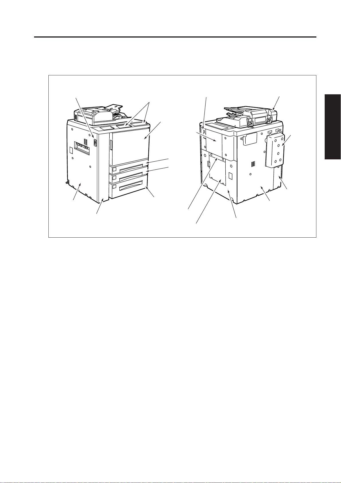
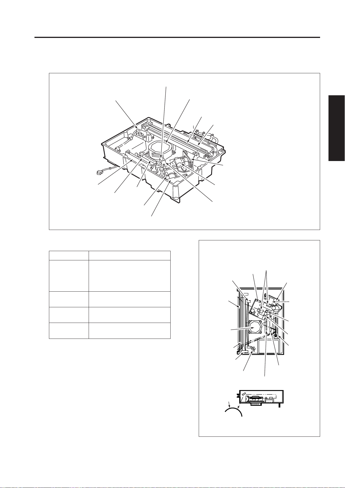
EXTERNAL SECTION
[1] Composition
Main switch
Operation panel
Front right door
Right side cover
(upper)
EXTERNAL SECTION
RADF
Left side cover
Left front door
Bypass tray
Tr a y 1
Tr ay 2
Tr a y 3
Right side cover
(middle)
Vertical
Conveyance
door
Cooling
cover
2 UNIT EXPLANATION
Optional cover
Rear cover
Right side cover
(lower)
2 - A - 1
Page 3
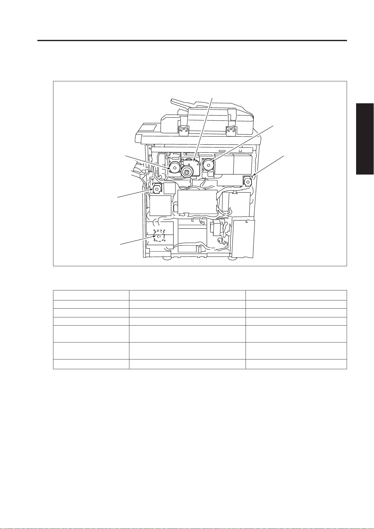
DRIVE SECTION
[1] Composition
DRIVE SECTION
Drum motor (M2)
Main motor (M1)
Developing motor (M3)
Loop roller motor (M6)
Paper feed motor (M4)
[2] Mechanisms
Mechanism
*1 Drum drive
*1 Developing drive
*1 Main drive
*1 Paper feed drive
*1 By-pass/loop drive
*1 Paper exit drive
Driven Parts
Drum, toner guide roller
Developing sleeve
Fixing upper roller
Tray 1/2/3, Vertical conveyance roller
(middle/lower)
By-pass feed roller, loop roller, vertical
conveyance roller (upper)
Paper exit roller
Paper exit motor
(M10)
2 UNIT EXPLANATION
Method
Gear drive (dedicated motor)
Gear drive (dedicated motor)
Gear drive (dedicated motor)
Gear drive (dedicated motor) + Belt
Gear drive (dedicated motor)
Gear drive (dedicated motor)
*1 Independent drive mechanisms
Drive mechanisms are driven by dedicated motors to ensure high-speed operation and to improve serviceability and developing performance.
2 - B - 1
Page 4

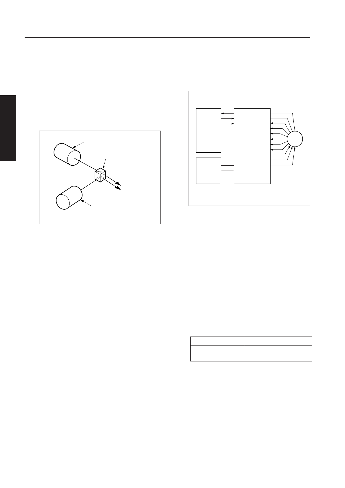
DRIVE SECTION
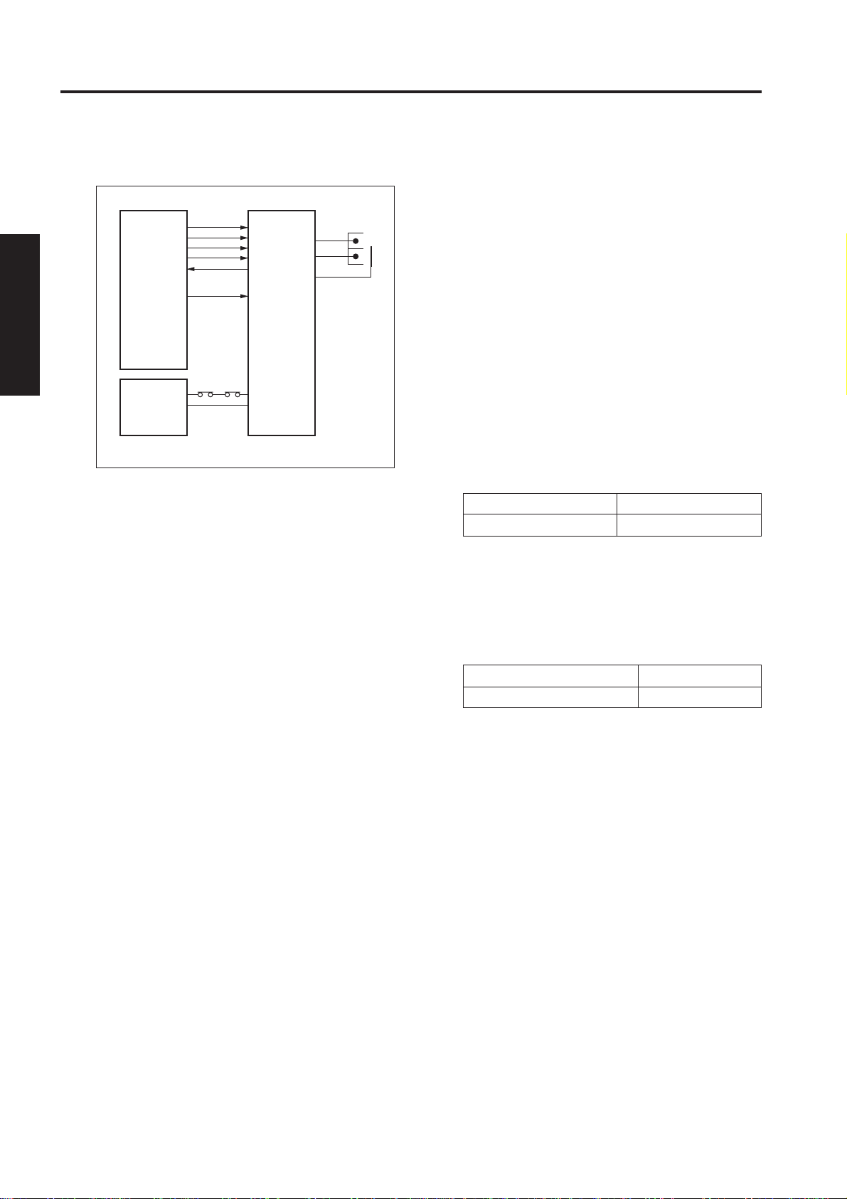
[3] M1 (Main) Control
MS2 MS1
24VDC
PGND
DCPS2
M1 CONT
M1 EM
2 UNIT EXPLANATION
M1 (main) is controlled by the PRCB (printer control
board) and the motor drive power is supplied from
DCPS2 (DC power supply unit 2).
1. Operation
M1 is a motor driven by 24V DC. It drives fixing
upper and lower rollers, paper conveyance belts,
and thick paper conveyance roller. M1 incorporates a speed controller circuit to send a signal
indicating abnormal rotation to PRCB when the
PLL lock has been released for longer than the
specified period of time.
M1 starts rotating when the START PRINT button is pressed and stops when the last copied
paper has been ejected. During the warm-up
operation, M1 rotates to rotate the fixing rollers.
When either one of the front doors of this machine
opens or closes, MS1 (interlock 1) or MS2
(interlock 2) actuates to stop supplying the DC
power to the motor, causing the M1 to stop.
PRCB
M1
[4] M2 (Drum) Control
MS2 MS1
24VDC
PGND
DCPS2
M2
M2CONT
M2 F/R
SGMD
M2 EN
PRCB
M2 (drum) is controlled by the PRCB (printer control
board) and the motor drive power is supplied from
DCPS2 (DC power supply unit 2).
1. Operation
M2 is a motor driven by 24V DC. It drives a drum,
toner guide brush, toner guide shaft, toner
conveyance screw, and separation claw swing
sections. M2 incorporates a speed sensor (encoder) to send a feedback signal to PRCB. Using
this signal, PRCB detects the rotational speed
and calculates the PWM duty to be given to the
motor, controlling the M2 speed. In addition to
the speed sensor, M2 also has a flywheel mechanism to ensure accurate and steady rotation.
M2 starts rotating when the ST ART PRINT button
is pressed and stops when the last copied paper
has been ejected.
When either one of the front doors of this machine
opens or closes, MS2 (interlock 1) or MS2
(interlock 2) actuates to stop supplying the DC
power to the motor, causing the M2 to stop.
2. Signals
a. Input signal
(1) M1 EM (M1 to PRCB)
M1 fault detection signal
[H]: Abnormal rotation (PLL lock has been
released for 2 to 3 seconds or longer.)
[L]: Normal rotation
b. Output signal
(1) M1 CONT (PRCB to M1)
M1 drive control signal.
[H]: M1 ON
[L]: M1 OFF
2. Signals
a. Input signal
(1) M2 EN (M2 to PRCB)
M2 motor encoder signal
b. Output signals
(1) M2 CONT (PRCB to M2)
M2 drive control signal (PCOM)
[L]: M2 ON
[H]: M2 OFF
(2) M2 F/R (PRCB to M4)
M2 rotational direction switchover signal
[H]: CCW (relative to motor shaft)
[L]: CW (relative to motor shaft)
2 - B - 2
Page 5
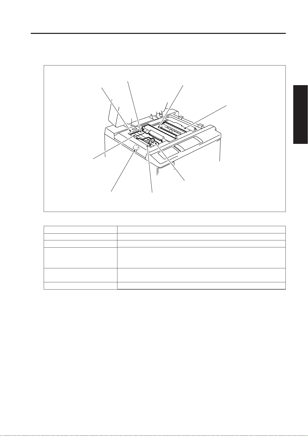
READ SECTION
[1] Composition
Optics rail (R)
Slit glass
READ SECTION
Scanner drive wire
Exposure unit
V-mirror unit
(2nd and 3rd mirrors)
2 UNIT EXPLANATION
Scanner cooling fan (FM7)
[2] Mechanisms
Mechanism
Light source
Exposure
Scanning
Lamp power supply
Optics cooling
CCD unit
A/D converter
board
Method
Xenon lamp
Light source shift slit exposure
Platen original scanning: 1st, 2nd, and 3rd mirrors are shifted.
RADF original scanning: Original is moved with light source held
stationary.
Lamp cord
Cooling fan
2 - C - 1
Page 6

READ SECTION
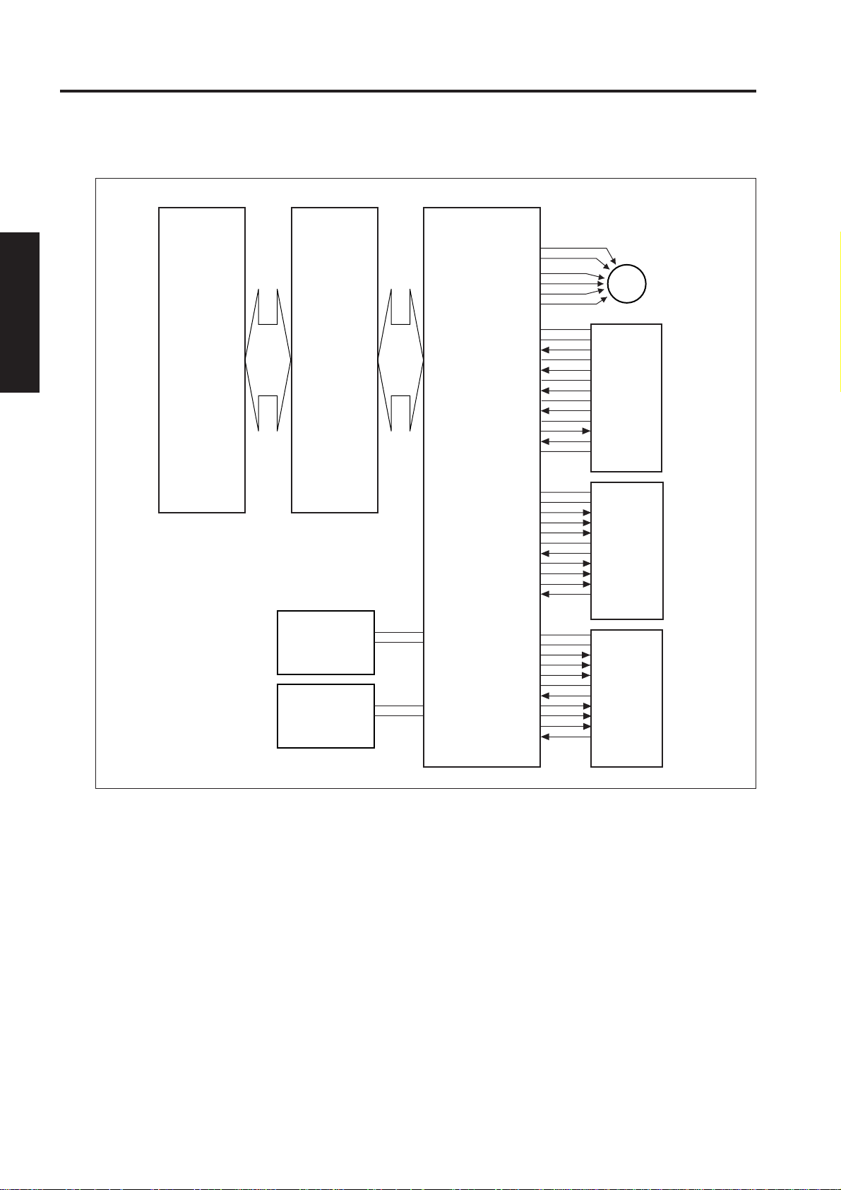
[3] M13 (Scanner Drive) Control
2 UNIT EXPLANATION
M13 CLK
M13 F/R
M13 CSEL
M13 V0
M13 V1
M13 V2
PS5
PS7
PS6
PS4
PRCB SCDB DCPS1
M13 DRIVE U
M13 DRIVE V
M13 DRIVE W
5VDC
PS5
SGND
PS7
5VDC
PS6
SGND
PS4
M13
PS5
PS7
PS6
PS4
24VDC
PGND
DCPS2
5VDC
SGND
M13 (scanner drive) is driven by the SCDB (scanner
drive board) and is controlled by the PRCB (printer
control board).
Related signals are PS4 (scanner reverse), PS5
(scanner HP), PS6 (original HP), and PS7 (ADF
brake).
1. Operation
a. Operation of M13
M13 is a 3-phase stepping motor driven using
the 3-phase bipolar constant-current drive
method. The motor is turned ON/OFF by
supplying/stopping clock pulses.
b. Movement speed of the exposure unit
Scanning speed
Operation mode
Scan
Movement speed
370 mm/sec (400 dpi, 1:1)
164.4 mm/sec (600 dpi,
1:1)
Forward
Home position
569.23 mm/sec
92.5 mm/sec
search
2 - C - 2
Page 7

c. Positions of sensors
Paper exit side Paper feed side
PS7 PS5 PS6 PS4
ADF break Scanner HP
PS7 PS5
READ SECTION
White correction
d. Exposure unit home position search
If the exposure unit is not at the home position
when the main switch is turned ON or when the
START PRINT button is pressed, the home
position is searched for in the follo wing manner:
(1) When the exposure unit is on the paper exit side
with respect to the home position
When the exposure unit is at PS7 (ADF brake)
(PS7 is ON), it moves forward at a low speed
until PS5 (scanner HP) turns ON and OFF again,
then it stops. Next the exposure unit moves
backward until PS5 turns ON again.
When the exposure unit is between PS7 and PS5,
it moves backward until PS7 turns ON before
moving forward as mentioned above.
(2) When the exposure unit is on the paper feed side
When the exposure unit is at PS5 (PS5 is ON), it
moves forward at a low speed until PS5 turns
OFF before moving as discussed in (1) above.
When the exposure unit is on the paper feed side
with respect to PS5, it stops after PS5 turns ON
and moves forward before moving as discussed
in (1) above.
400dpi shading correction
600dpi shading correction
2 UNIT EXPLANATION
f. ADF copy operation
PS7 PS5
Original read
position
e. Read with shading correction
When L1 (exposure lamp) is turned ON, the
exposure unit mov es toward the paper e xit side,
thus reading the light reflected by the white
reference plate installed underneath the glass
stopper plate and performing white correction.
Then, L1 is turned OFF for black correction,
returning to the home position. Shading correction
is performed at 400 dpi and 600dpi.
g. Platen copy operation
Scanner HP
PS5 PS6 PS4
AE scan
Original area judgment
Exposure scan
Home position search
Original HP
Scanner
return
2 - C - 3
Page 8

READ SECTION
2. Signals
a. PRCB input signals
(1) PS4 (PS4 to SCDB to PRCB)
Scanner reverse detection signal.
In the platen mode, the return position of the
exposure unit is detected on the original's leading
edge side.
[L]: The exposure unit is detected.
[H]: The exposure unit is not detected.
(2) PS5 (PS5 to SCDB to PRCB)
Scanner home position detection signal.
The reference position for the home position of
2 UNIT EXPLANATION
the exposure unit is detected.
[L]: The exposure unit is detected.
[H]: The exposure unit is not detected.
(3) PS6 (PS6 to SCDB to PRCB)
Original home position detection signal.
In the platen mode, the reference position for the
original's leading edge is detected.
[L]: The exposure unit is detected.
[H]: The exposure unit is not detected.
(4) PS7 (PS7 to SCDB to PRCB)
ADF brake detection signal.
In the DF mode, the exposure reference position
is detected.
[L]: The exposure unit is detected.
[H]: The exposure unit is not detected.
b. PRCB output signals
(1) M13 CLK (PRCB to SCDB)
Clock signal for M13
(2) M13 F/R (PRCB to SCDB)
M13 rotational direction switchover signal.
[L]: The exposure unit is moved toward the
paper exit side.
[H]: The exposure unit is moved toward the
paper feed side.
(3) M13 CSEL (PRCB to SCDB)
M13 excitation switchover signal.
[L]: 2-/3-phase excitation
[H]: 2-phase excitation
(4) M13 V0 to V2 (PRCB to SCDB)
M13 excitation current switchover signal.
c. OPDB output signals
(1) M13 DRIVE, U, V, W (SCDB to M13)
M13 drive control signals.
These signals are used to control rotation of M13.
By supplying and stopping clock pulses, the motor
is turned ON/OFF and the rotational direction is
switched.
[4] Exposure control
L1 CONT
PRCB SCDB
24VDC
L1 CONT
L1 (exposure lamp) is driven by the L1 INVB (L1
inverter) and is controlled by the PRCB (printer control
board) via the SCDB (scanner drive board).
1. Operation
L1 is a xenon lamp driven by the inverter circuit.
The xenon lamp can emit a constant quantity of
light and generates less heat than other lamps,
requiring neither light quantity controller circuit
nor thermal protector circuit that have been used
in the conventional machines. However, since
L1 is held lit when the exposure unit is
nonoperational in the DF mode, a FM7 (scanner
cooling) is installed in the read section.
2. Signals
a. Output signals
(1) L1 CONT (PRCB to SCDB to L1 INVB)
L1 ON/OFF control signal.
[L]: L1 ON
[H]: L1 OFF
L1 INVB
24VDC
PGND
DCPS2
LV
HV
L1
2 - C - 4
Page 9
READ SECTION
5VDC
PS62
SGND
PS63
PS64
PS65
PS66
PS67
PS68
PRCB ICB IFB
PS62
PS63
PS64
PS65
PS66
PS67
PS68
DCPS1
5VDC
SGND
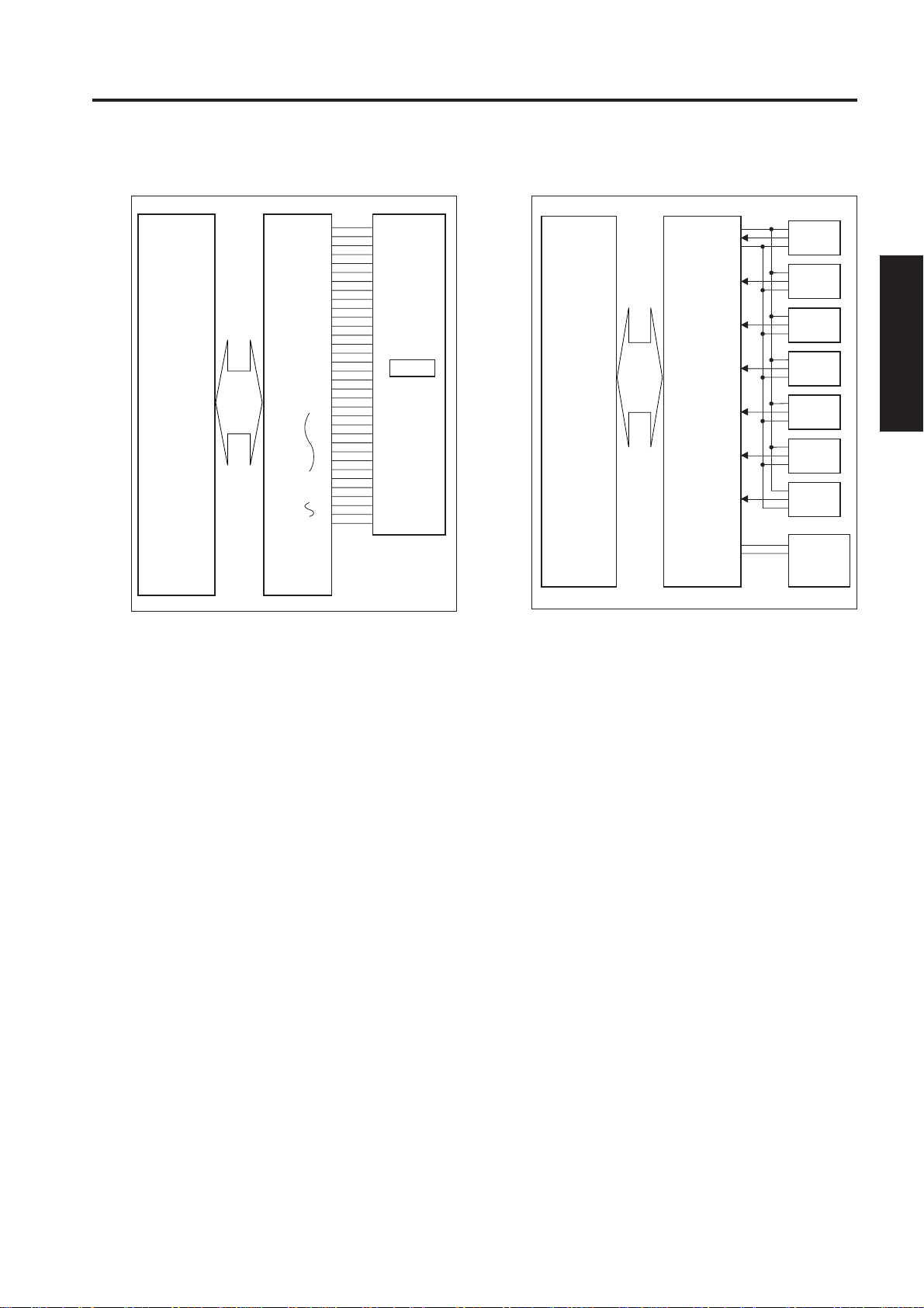
[5] Original Read Control
TCK1
SGND
TCK2
SGND
RCK1
SGND
RCK1
SGND
TG
CLMP
S CK
S IN
S LD
MD0
MD1
MD2
S LP
SGND
AD CK
APR
OD0
OD8
SGND
ED0
ED3
ICB IFB ICB
[6] APS Control
CCD
ADB
2 UNIT EXPLANATION
Original read control is performed by the ADB (A/D
converter board) and CCD sensor installed in the ADB.
1. Operation
The light reflected by the exposed original is input
to the CCD sensor through the lens. The analog
voltage corresponding to the quantity of input light
is A/D-converted in the ADB, being output to the
ICB (image control board).
a. Original read
The original read timing is as follows:
(1) Platen mode
Specified interval after exposure unit turns PS6
(original HP) ON.
(2) DF mode
After lapse of the specified time after the original's
leading edge turns ON PS308 (Original).
The APS method used in the platen mode is different
from that used in the DF mode.
The signal read by the APS sensor or the original size
detection sensor of the RADF is processed by the CB
(control board).
1. Operation
a. APS detection
(1) DF mode
The original size is detected according to the
combination of ON/OFF states of PS302 (original
size detection 1) and PS303 (original size
detection 2) and the resistance value of VR301
(original size detection).
2 - C - 5
Page 10

READ SECTION
(2) Platen mode
The paper size is detected according to the
combination of ON/OFF states of PS62 (APS 1),
PS63 (APS 2), PS64 (APS 3), PS65 (APS 4),
PS66 (APS 5), PS67 (APS 6), and PS68 (APS
7).
The APS sensor consists of LEDs and
photosensors. Lights emitted from the LEDs is
reflected by the original and received by
photosensors.
2 UNIT EXPLANATION
Paper exit side
Relationships between sensors and original sizes
are as follows:
Sensor
Paper
size
B5R
B5
B4
A4R
A4
A3
8.5 x 11R
8.5 x 11
8.5 x 14
11x 17
Min. size
PS63
PS62 PS68
PS66
PS64
PS67
PS65
Photo sensor
LED
PS62 PS63 PS64 PS65 PS66 PS67 PS68
ON
OFF
b. APS detection timing
The APS detection timing differs between the
platen mode and DF mode.
(1) DF mode
When the DF mode is selected or original is set
on the RADF original feed tray, APS detection
takes place using PS302 (original size detection
1), PS303 (original size detection 2), and VR301
(original size detection).
(2) Platen mode
When RADF is closed and PS315 (APS timing)
turns ON, APS detection takes place using PS62
to PS68.
2. Signals
a. Input signals
(1) PS62 (PS62 to ICB IFB)
Paper size detection signal
[L]: Paper is detected.
[H]: Paper is not detected.
(2) PS63(PS63 to ICB IFB)
Paper size detection signal
[L]: Paper is detected.
[H]: Paper is not detected.
(3) PS64 (PS64 to ICB IFB)
Paper size detection signal
[L]: Paper is detected.
[H]: Paper is not detected.
(4) PS65 (PS65 to ICB IFB)
Paper size detection signal
[L]: Paper is detected.
[H]: Paper is not detected.
(5) PS66 (PS66 to ICB IFB)
Paper size detection signal
[L]: Paper is detected.
[H]: Paper is not detected.
(6) PS67 (PS67 to ICB IFB)
Paper size detection signal
[L]: Paper is detected.
[H]: Paper is not detected.
(7) PS68 (PS68 to ICB IFB)
Paper size detection signal
[L]: Paper is detected.
[H]: Paper is not detected.
2 - C - 6
Page 11

READ SECTION
[7] AE Control
ICB IFB ICB
TCK1
SGND
TCK2
SGND
RCK1
SGND
RCK1
SGND
TG
CLMP
S CK
S IN
S LD
MD0
MD1
MD2
S LP
SGND
AD CK
APR
OD0
OD8
SGND
ED0
ED3
CCD
ADB
(2) DF mode
The image at the leading edge of the original is
read when the PRINT START button is pressed.
The read data is used to measure the image
density on the original.
<AE sampling area>
(1) Main scanning direction
• 10-mm area inside the original detected by
APS
(2) Sub scanning direction
Range between 2mm to 7.3mm from the leading
edge of the original.
2 UNIT EXPLANATION
The CCD sensor detects the image density on an
original during AE scanning to select the optimum copy
gamma correction curve.
AE processing is controlled by the ICB (image control
board).
1. Operation
a. AE detection
(1) Platen mode
The image density on an original is measured
while the exposure unit moves from the home
position to the leading edge of the original after
depression of the START PRINT button.
<AE sampling area>
(1) When ADF is closed
10mm inside perimeter of original size detected
by APS.
(2) When ADF is opened
Entire original area detected by forward scanning.
2 - C - 7
Page 12
WRITE UNIT
[1] Composition
WRITE UNIT
Cylindrical lens 1
Index sensor board
2nd mirror
[2] Mechanisms
Mechanism
*1 Scan
Light source
*2 Positioning
*3 Laser beam
combining
fθ lens 2
fθ lens 1
Collimator lens unit 1
Laser driver board LD1
Method
Polygon mirror
Rotational speed:
21,850.4 rpm (400dpi)
32,775.6 rpm (600dpi)
Laser diodes (two)
(Output: Max. 20 mW)
Index sensor
Fine adjustment prism
Beam combining prism
Polygon mirror
Cylindrical lens 2
3rd mirror
Collimator lens unit 2
Beam combining prism
CY2 lens
3rd mirror
Polygon
mirror
Laser driver board LD2
Semiconductor
laser LD2
Compression prism
2 UNIT EXPLANATION
Semiconductor laser
LD1
Collimator
lens unit
Beam
combining
prism
CY1 lens
*1 Path of laser light
The light output from semiconductor laser is
radiated onto the OPC drum via the collimator
lens, compression prism, fine adjustment prism,
beam combining prism, cylindrical lens 1, polygon
mirror,fθ lens 1, fθ lens 2, second mirror,
cylindrical lens 2, and third mirror.
2 - D - 1
Glass cover
Index mirror
Index sensor
OPC drum
2nd mirror
fθ lens 2
fθ lens 1
Page 13
WRITE UNIT
*2 Positioning
Each laser beam is positioned by the
compression prism and fine adjustment prism.
*3 Laser beam combining
Two laser beams output at right angle to each
other are redirected in the same direction using
the beam combining prism.
2 UNIT EXPLANATION
Semiconductor laser 1
Laser 1 beam passes
Laser 2 beam
reflected
Beam combining
prism
Semiconductor
laser 2
[3] M17 (Polygon ) Control
M17 is driven by the PMDB (polygon driver board)
and is controlled by the PRCB (printer control board).
M17 EM
M17 CLK
M17 CONT
PRCB
24VDC
PGND
DCPS2 PMDB
1. Operation
a. Explanation of operation
M17 is a 3-phase brushless DC motor which is
driven by the 3-phase bipolar method. The
current flowing through the coil is switched
according to the position of the rotor detected by
the position sensor (magnetic sensor) in the
motor.
This motor rotates the polygon mirror to scan the
laser beams from LDB1 and 2 (laser driver boards
1 and 2) in the axial direction of the drum. Its
rotation is held constant by PLL control.
b. Rotational speed
M17 is powered by 24 VDC and its speed is as
follows:
SGND
24VDC
M17 MAG A’
M17 MAG A
M17 MAG B’
M17 MAG B
M17 MAG C’
M17 MAG C
M17 DRIVE C
M17 DRIVE B
M17 DRIVE A
M17
2 - D - 2
Machine state Rotational speed
400 dpi 21,850.4 rpm
600 dpi 32,775,6 rpm
2. Signals
a. PRCB input signals
(1) M17 EM (PMDB to PRCB)
This signal indicates the clock synchronization
state of M17.
[L]: Synchronous (normal)
[H]: Asynchronous (abnormal)
Page 14

b. PRCB output signals
(1) M17 CONT (PRCB to PMDB)
This signal turns ON/OFF M17.
[L]: M17 ON
[H]: M17 OFF
(2) M17 CLK (PRCB to PMDB)
This is a reference clock signal f or PLL-controlling
M17 in PMDB.
c. PMDB input signals
(1) M17 MAG A/A’ (M17 to PMDB)
(2) M17 MAG B/B’ (M17 to PMDB)
(3) M17 MAG C/C’ (M17 to PMDB)
Output signals from the position sensor (magnetic
sensor) incorporated in M17.
The PMDB detects the position of the motor
rotator using these signals, switching among
outputs, M17 DRIVE A to C.
d. PMDB output signals
(1) DRIVE A to C (PMDB to M17)
M17 drive signals.
M5 DRIVE A to C supplies the corresponding
voltages to M17. Pulses of the voltages
applied to M17 are shown below. The pulse
widths of the PMDB output signals change as
shown below depending on the state of M17
rotation, causing the effective values of the
voltages supplied to M17. Thus, the M17
speed can be controlled.
WRITE UNIT
2 UNIT EXPLANATION
M5 DRIVE A
M5 DRIVE B
M5 DRIVE C
2 - D - 3
Page 15
WRITE UNIT
[4] Image Write Control
2 UNIT EXPLANATION
M24 PWR A
M24 PWR B
M24 DRIVE A
M24 DRIVE A’
M24 DRIVE B
M24 DRIVE B’
5VDC
SGND
M INDEX 1
SGND
M INDEX 2
SGND
S INDEX1
SGND
S INDEX 2
SGND
HL VL
IPR
SGND
M24
INDEXSB
ADB
ICB
5VDC
SGND
DCPS1
24VDC
PGND
DCPS2
The analog image data from the CCD sensor is A/Dconverted by the ADB (A/D conv erter board), then sent
to the ICB (image control board) for data processing.
The processed image data is converted into a laser
beam according to the control signal received from
the ICB through the ICB IFB (ICB I/F board), then the
beam is radiated onto the drum surface. Two lasers
5VDC
SGND
LD1 SH
LD1 ENB
LD1 VIDEO
SGND
LD1 ALM
LD1DCLK
LD1 DI
LD1 LD
LD1 PR
LDB1
5VDC
SGND
LD2 SH
LD2 ENB
LD2 VIDEO
SGND
LD2 ALM
LD2 DCLK
LD2 LD
LD2 AD
LD2 PR
LDB2ICB IFB
are provided to write two lines of image data per scan.
The write start position is detected by the INDXSB
(index sensor board). The ICB has an E-RDH
(electronic RDH processing) function to store digitized
data. Various editing functions can be performed
based on this data.
2 - D - 4
Page 16
WRITE UNIT
1. Operation
a. Image processing
The following processing is performed by the ICB
(image control board):
(1) AOC (Auto Offset Control)
During shading correction, a read operation takes
place while L1 (exposure lamp) is OFF, and the
analog offset voltage of the output from the CCD
sensor is automatically adjusted so that the
resulting level is the lower limit of the A/D
converter.
(2) AGC (Auto Gain Control)
During shading correction, the white reference
plate is read, and the amplification of the analog
output from the CCD sensor is automatically
adjusted so that the resulting level is the upper
of the A/D converter.
(3) Shading correction
<Timing>
• When SW1 (main switch) is turned ON
(4) Brightness/density conversion
(5) EE processing
(6) Text/dot pattern judgment
(7) Filtering/magnification change processing
(8) Magnification change processing
(9) Copy gamma correction
(10)Skew correction
(11)Error diffusion processing
(12)Data compression
(13)Write density control
b. Write
The ICB (image control board) sends image data
on a pixel basis to LDB1 and LDB2 according to
the control signals from the PRCB (printer control
board).
LDB1 and LDB2 cause the lasers to emit for a
period corresponding to the image data. This laser light is radiated onto the drum surface.
(1) MPC (Maximum Power Control)
ICB informs LDB1 and LDB2 of the maximum
output value and sets that value for the laser
beam emission. LDB1 and LDB2 store this setting
value and maintain the quantity of the laser beam
emission using the APC (Auto Power Control).
<MPC timing>
a) When SW1 (main switch) is turned ON
(2) APC (Auto Power Control)
The ICB outputs an APC start instruction to the
LDB at the following timing, after MPC is set.
<APC timing>
a) The LDB1 and LDB2 automatically monitor the
laser drive current one line at a time, and
controls it so that the light intensity remains
the MPC value.
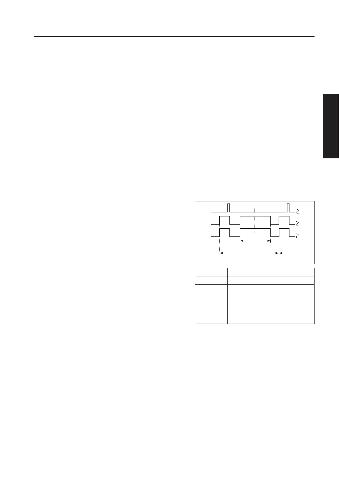
(3) Write timing
a) Main scanning direction
Using INDEX signal from INDXSB, determines
the laser write reference position for each scan
in the drum rotation direction, and writes the
image to copy paper using the paper position
information derived from the paper position
detection by PS1(paper mis-centering).
INDEX
Laser
output 1
Laser
output 2
ab c d e
Symbol
a
b
b-c
c-d
d-e
Image area
1st scanning 2nd scanning
Description
Laser goes ON for first scan
Index sensor goes ON.
The timing at the left is controlled
by counting the LD1 IRCLK and
LD2 IRCLK signals. It differs
depending on the document size.
b) Sub scanning direction
Specified interval after PS44 (registration)
detects the tip of the copy paper.
(4) Laser beam position correction
a) Main scanning direction
The index sensor detects the deviation of the
positions of the two beams. This error is
corrected by changing the timing of the light
emission from the laser.
b) Sub scanning direction
The index sensor detects the deviation of the
positions of two beams in order to change the
angle of the fine adjustment prism of the LD1
laser using M24 (laser correction), thus adjusting the vertical angle of the beam.
2 UNIT EXPLANATION
2 - D - 5
Page 17

WRITE UNIT
2. Signals
a. ICB IFB input signals
(1) M INDEX 1, 2 (INDEXSB to ICB IFB)
This is an index signal used to detect deviation
of vertical scanning.
(2) S INDEX 1, 2 (INDEXSB to ICB IFB)
This is an index signal used to detect deviation
of horizontal scanning.
(3) IPR (INDEXSB to ICB IFB)
This signal monitors the INDEXSB power supply .
[H]: Normal
[L]: Abnormal
2 UNIT EXPLANATION
(4) LD1 ALM (LDB1 to ICB IFB)
This signal indicates the state of the LD1 laser
drive current.
[H]: Normal
[L]: Abnormal
(5) LD1 PR (LDB1 to ICB IFB)
LD1 power supply monitor signal.
[H]: Normal
[L]: Abnormal
(6) LD2 ALM (LDB2 to ICB IFB)
This signal indicates the state of the LD2 laser
drive current.
[H]: Normal
[L]: Abnormal
(7) LD2 PR (LDB2 -> ICB IFB)
LD2 power supply monitor signal.
[H]: Normal
[L]: Abnormal
b. ICB IFB output signals
(1) M24 PWR A (ICB IFB to M24)
M24 A-phase drive signal.
(2) M24 PWR B (ICB IFB to M24)
M24 B-phase drive signal.
(3) M24 DRIVE A/A'(ICB IFB to M24)
M24 A-phase drive pulse signal.
(4) M24 DRIVE B/B' (ICB IFB to M24)
M24 B-phase drive pulse signal.
(5) LD1 SH (ICB IFB to LDB1)
One scan line equivalent APC sampling signal.
(6) LD1 ENB (ICB IFB to LDB1)
Laser APC function ON/OFF control signal.
Laser beam emission stops when it is OFF.
(7) LD2 SH (ICB IFB to LDB2)
One scan line equivalent APC sampling signal.
(8) LD2 ENB (ICB IFB to LDB2)
Laser APC function ON/OFF control signal.
Laser beam emission stops when it is OFF.
(9) LD1 VIDEO (ICB IFB to LDB1)
LD1 laser image signal.
(10)LD2 VIDEO (ICB IFB to LDB2)
LD2 laser image signal.
(11)LD1 DCLK (ICB IFB to LDB1)
LD1 clock signal for MPC value data transmission.
(12) LD1 DI (ICB IFB to LDB1)
LD1 data signal for MPC.
(13) LD1 AD (ICB IFB to LDB1)
LD1 MPC value storage command signal.
(14) LD2 DCLK (ICB IFB to LDB2)
LD2 clock signal for MPC value data transmission.
(15) LD2 DI (ICB IFB to LDB2)
LD2 data signal for MPC.
(16) LD2 AD (ICB IFB to LDB2)
LD2 MPC value storage command signal.
2 - D - 6
Page 18
DRUM UNIT
[1] Composition
DRUM UNIT
Charging corona unit
Developing unit
Separation claws
Cleaning/toner recycle unit
Cleaning/toner recycle unit
[2] Mechanisms
Mechanism
Carriage support
PCL/TSL
*1 Auxiliary separa-
tion
*2 Conveyance
assistance
PCL
Method
Fixed rail
LED
Separation claws
Ratchet wheel
Charging corona unit
TSL
2 UNIT EXPLANATION
Separation claw solenoid
Developing unit
Transfer and separation corona unit
mechanism slides the separation claws about
5 mm back and forth in parallel with the drum
surface.
Separation claw
Separation
claw
solenoid(SD4)
The drum unit is an integral assembly consisting of a
drum, charging corona unit, developing unit, cleaning
unit, toner recycle unit, PCL, and separation claws.
*1 Auxiliary separation
• To prevent paper jamming, three separation
claws are used to separate paper from the
drum forcibly. These separation claws are
pressed against the drum or detached from it
by turning ON/OFF the separation claw
solenoid (SD4).
• To prevent a specific part of image copied
paper from being stained and to prevent the
drum from being scratched, the swing
*2 Conveyance assistance
The thick paper conveyance ability has been
improved by the use of ratchets.
2 - E - 1
Page 19

DRUM UNIT
[3] Separation Claw Control
24VDC
SD4 DRIVE
DCDB
SD4 CONT
M2CONT
M2EM
24VDC
PGND
PRCB
24VDC
DCPS2
MS2 MS1
PGND
2 UNIT EXPLANATION
Separation claws are driven by SD4 (separation claw
drive solenoid). Separation claws are slid by M2 (main).
SD4 is controlled by the PRCB (printer control board)
via the DCDB (DC drive board).
1. Operation
a. Separation claw ON/OFF control
SD4 is a pull-type solenoid powered by 24 VDC .
It turns ON to press separation claws against the
drum to help image copied paper separate.
(1) SD4 operation timing
SD4 turns ON after a lapse of specified time from
turning ON of PS45 (leading edge detection). It
turns OFF after a lapse of the time set by the
PRCB timer.
b. Separation claw swing control
Separation claws are swung by M2 (main) via
the cam mechanism.
2. Signals
a. CB output signal
(1) SD4 CONT (CB to DCDB)
SD4 drive control signal.
[L]: SD4 ON
[H]: SD4 OFF
b. DCDB output signal
(1) SD4 DRIVE (DCDB to SD4)
SD4 drive control signal.
[L]: SD4 ON
[H]: SD4 OFF
SD4
M2
[4] Paper Guide Plate Control
GP CONT
PRCB
24VDC
PGND
DCPS2
ADUSDB
To prevent toner from adhering to the paper guide
plate, a constant voltage is applied to the paper guide
plate. This voltage is supplied from HV2 (high v oltage
unit 2) and is controlled by the serial data sent from
the PRCB (printer control board) via the ADUSDB
(ADU frame control board). When the front door of
this machine opens or closes, MS1 (interlock 1) or
MS2 (interlock 2) operates to interrupt the DC power
supply to HV2, stopping the voltage application to the
paper guide plate.
1. Operation
a. ON/OFF timing
Turning ON/OFF in sync with M2 (drum)
b. Applied voltage
-500 VDC
2. Signal
a. Output signal
(1) GP CONT (ADUSDB to HV2)
This signal controls turning ON/OFF the voltage
application to paper guide plate.
[L]: Voltage applied
[H]: Voltage not applied
GP
HV2
2 - E - 2
Page 20
DRUM UNIT
[5] Drum Potential Control
DPS DRIVE A
DPS DRIVE B
DPS ANG 1
DPS ANG 2
DPSB
PRCB
DCPS2
DPS ANG
SGND
24VDC
PGND
The drum potential is detected by the DPS (Drum
Potential Sensor) and send the PRCB (printer control
board) via the DPSB (drum potential sensor board).
1. Operation
Drum potential control is performed to keep the
drum surface potential constant and maintain
image quality regardless of the usage
environment or the number of copies.
(1) Method
The image is created on the drum surface by the
difference in the exposure potential and
developing bias. A patch is created with laser
PWM maximum.
The developing bias is corrected so that the
difference between the after exposure potential
(solid black area) and the developing bias is
always 500V and the charging current and the
grid voltage are corrected so that the difference
between the before exposure potential and
developing bias is 150V.
(2) Timing
a) When the fixing temperature is lower than 50°C
at power ON.
b) At the end of job after every 5,000 copies.
DPS
2. Signals
a. PRCB Input signals
(1) DPS ANG (DPSB to PRCB)
Analog signal corresponding to the drum
charging potential.
b. DPSB Input signals
(1) DPS ANG 1 and 2(DPS to DPSB)
Analog signal corresponding to the drum
charging potential.
c. DPSB output signals
(1) DPS DRIVE A and B(DPSB to DPS)
DPS(drum potential) drive signal.
2 UNIT EXPLANATION
2 - E - 3
Page 21
DRUM UNIT
[6] HTR1 (drum heater) Control
12VDC
5VDC
DRUM TEMP
AGND
TH5 ANG1
TH5 ANG2
TH5
12VDC
5VDC
SGND
DCPS1
2 UNIT EXPLANATION
AC(H)
AC(C)
The drum is heated by HTR1 (drum heater). The
PRCB (printer control board) detects the drum
temperature with TH5 (drum temperature sensor) and
controls HTR1 through ACDB (AC drive board). TH5
is a sensor that changes resistance according to the
detected temperature. Therefore, its value is
converted to voltage by DTSB (drum temperature
sensor board) and output to PRCB.
1. Operation
a. Temperature Control
HTR1 is normally maintained at 30°C and the
temperature is increased only when humidity is
high. When warming up under high humidity , the
drum is rotated after the drum temperature
reaches a specified value and then drum potential
control, Dmax control, and gradation correction
control are performed. When warm up completes,
HTR1 is turned ON/OFF to maintain the drum
temperature constant. Under high humidity, the
temperature is raised to 45°C every 30 minutes
and then returned to specified temperature to
prevent dew condensation.
b. Error detection
HTR1 is equipped with self recover type
thermostat to prevent abnormal increase in drum
temperature. The thermostat turns off at 70°C.
HTR1 CONT
PRCB
HTR1 CONT
HTR1 DRIVE
ACDB
DTSB
HTR1
2. Signals
a. PRCB input signal
(1) DRUM TEMP (TH5 to DTSB to PRCB)
Drum temperature signal. The relationship
between drum temperature and output voltage
is linear.
b. PRCB output signal
(1) HTR1 CONT (PRCB to ACDB to HTR1)
Drum heater ON/OFF control signal
c. ACDB output signal
(1) HTR1 CONT (DTSB to HTR1)
Drum heater ON/OFF control signal
(2) HTR1 DRIVE (DTSB to HTR1)
Drum heater drive power supply line
2 - E - 4
Page 22
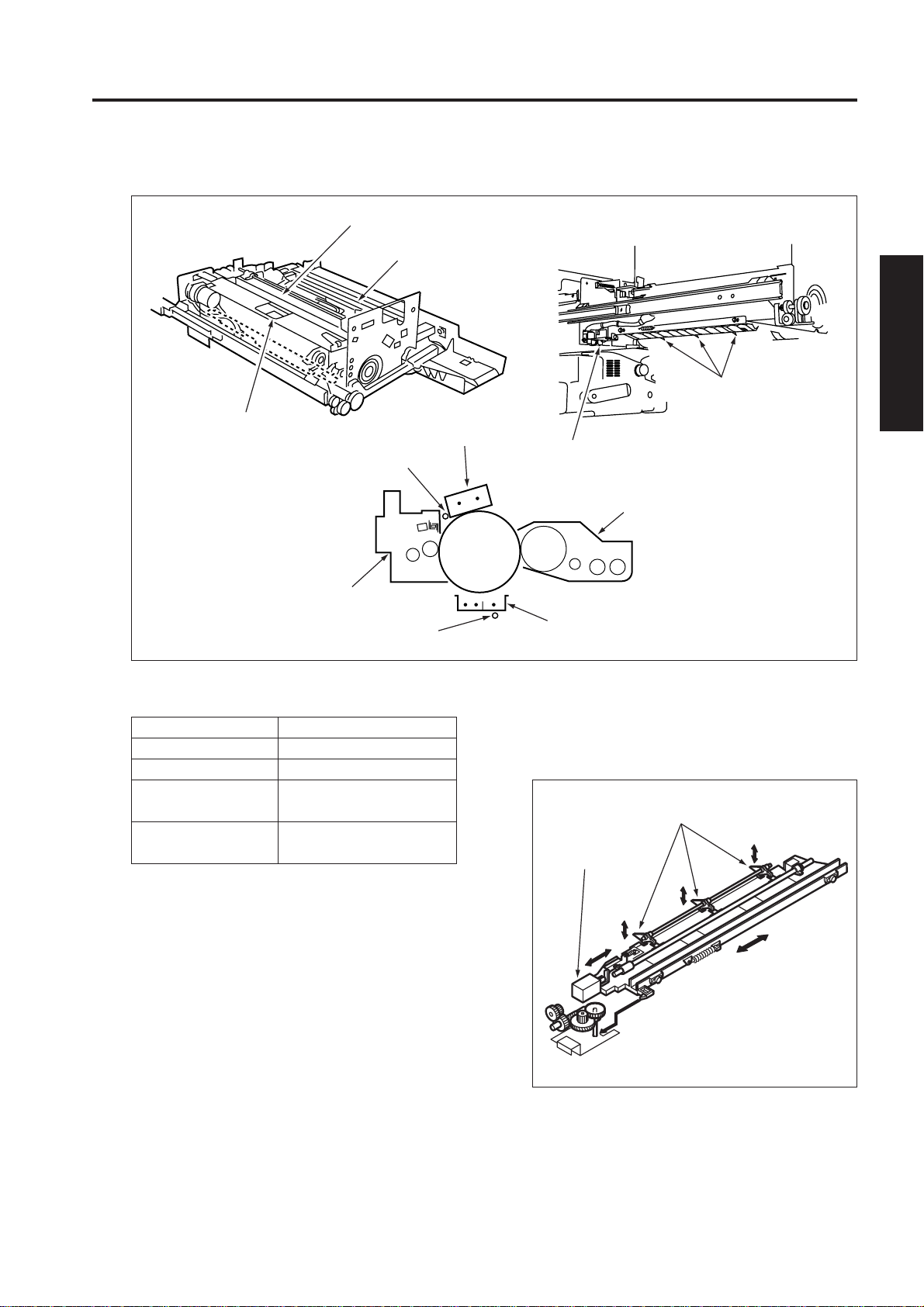
CORONA UNIT SECTION
[1] Composition
CORONA UNIT SECTION
<Charging corona unit>
Charging corona unit
Charging
wire cleaning
motor (M23)
Charging
wire cleaning
material
[2] Mechanisms
Mechanism
*1 Charging
Scorotron (DC negative
corona discharge). Discharge
wire: Tungsten, 0.06 mm dia.
(gold-plated skin path: with
automatic wire cleaner). Grid
control: Gold-plated stainless
plate
*2 Toner
transfer
DC positive corona discharge.
Discharge wire: Oxide film
tungsten, 0.06 mm dia., with
automatic wire cleaner.
Toner
detach
AC/DC corona discharge.
Discharge wire: Oxide film
tungsten, 0.06 mm dia., with
automatic wire cleaner
*1 Cleaning the charging wire
The charging corona unit has wire cleaning pads.
The charging wire cleaning pad drive motor
moves the charging wire cleaning pad back and
forth, removing toner and dirt from the wires.
Method
PCL
<Transfer and separation corona unit>
Transfer entrance
guide plate
Plunging prevention plate
Charging
wire
Guide rollers
Transfer
corona unit
Separation corona unit
Charging wire
cleaning material
*2 Cleaning the transfer and separation wires
The transfer and separation wire unit has a wire
cleaner. The transfer and separation wire
cleaning pads drive motor moves the transfer and
separation wire cleaning pads back and forth,
removing toner and dirt from the wires.
Transfer wire
Separation wire cleaning
material
cleaning material
Transfer wire
2 UNIT EXPLANATION
2 - F - 1
Separation wire
Page 23
CORONA UNIT SECTION
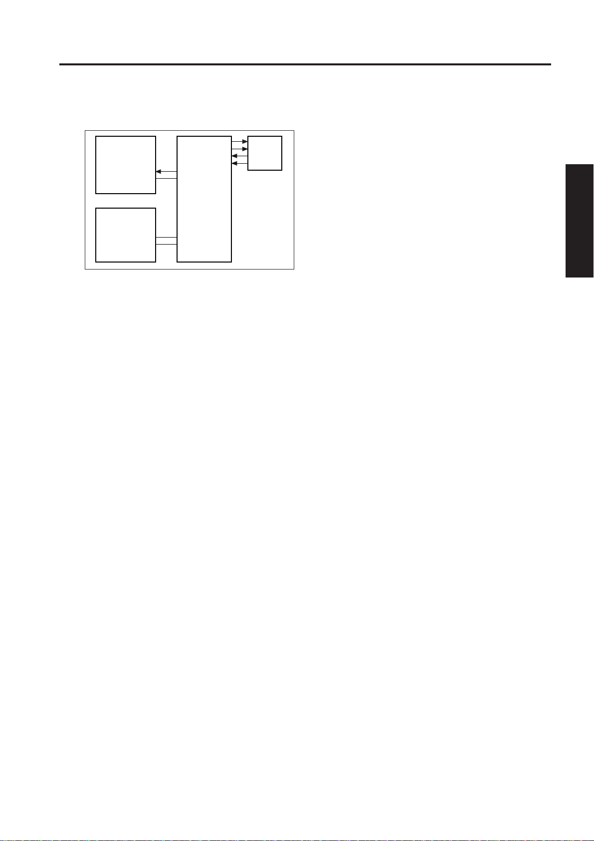
[3] Charging Control
C CONT1
C CONT2
C SHIFT
SGND
G SHIFT
PRCB
2 UNIT EXPLANATION
24VDC
DCPS2 HV1
MS2 MS1
PGND
Charging control is performed using the serial data
sent from the PRCB (printer control board) via the
ADUSDB (ADU stand drive board). HV1 (high voltage
unit 1) is used to apply voltage to the charging wires.
1. Operation
a. Charging
A Scorotron charging method is used. 24 VDC
supplied from DCPS2 is raised to a negative DC
voltage which is then discharged after being
applied to the charging wire.
When the front door of this machine opens or
closes, MS1 (interlock 1) or MS2 (interlock 2)
operates to interrupt the DC power supply to HV1,
stopping the voltage supply to the charging
corona unit and charging grid.
b. Grid voltage
The grid voltage is output from HV1 to the
charging plate.
C SIG
CHARGING
2. Signals
a. Input signal
(1) C SIG (HV1 to PRCB)
Leak or short detection signal.
[L]: Normal
[H]: Abnormal
b. Output signals
(1) C CONT1, 2 (PRCB to HV1)
Charging 1/2 output ON/OF control signal.
[L]: Charging voltage ON
[H]: Charging voltage OFF
(2) C SHIFT (PRCB to HV1)
Charging corona unit output level control signal.
The output to the charging corona unit is
controlled according to the duty ratio of the pulse
(PWM) signal sent from the PRCB.
C SHIFT duty 20% to 80%
Charging output range -500µA to -1900µA
(3) G SHIFT (PRCB to HV1)
Charging grid output level control signal.
The output to the charging grid is controlled
according to the duty ratio of the pulse (PWM)
signal sent from the PRCB.
G SHIFT duty 20% to 80%
Grid voltage output range -400 V to -1000 V
2 - F - 2
Page 24

CORONA UNIT SECTION
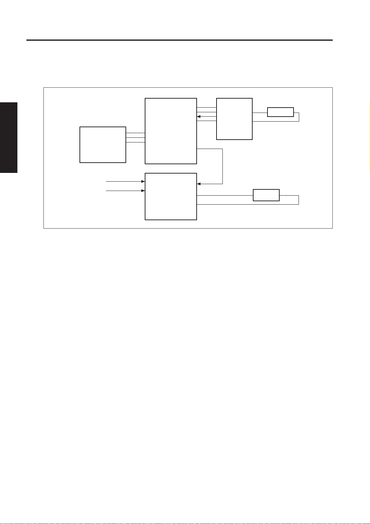
[4] Transfer/Separation Control
24VDC
PGND
DCPS2
MS2 MS1
24VDC
T CONT
S CONT
SEL
T SIG
S SIG
SGND
PGND
ADUSDB
S SHIFT(DC)
S FB(AC)
S FB(DC)
S SHIFT(AC)
T SHIFT
PRCB HV2
The transfer and separation corona unit is controlled
by the PRCB (printer control board) and ADUSDB
(ADU stand drive board) via the HV2 (high voltage
unit 2). Between the the PRCB and ADUSDB, signals
are exchanged using serial data. When the front door
of this machine opens or closes, MS1 (interlock 1) or
MS2 (interlock 2) operates to interrupt the DC power
supply to HV2, stopping the voltage supply to the
transfer and separation corona unit.
SEPARATION
TRANSFER
b. PRCB output signals
(1) T SHIFT (PRCB to HV2)
Transfer corona unit output level control signal.
This signal controls the level of the output to the
transfer corona unit according to the duty ratio of
the pulse (PWM) signal sent from the PRCB.
T SHIFT duty 20% to 80%
Transfer DC output range
70µA to -700µA
(2) S SHIFT (DC) (PRCB to HV2)
Separation corona unit output level control signal.
This signal controls the level of the output (DC
bias component) to the separation corona unit
according to the duty ratio of the pulse (PWM)
signal sent from the PRCB.
S SHIFT duty 20% to 80%
Separation DC output range
0µA to -300µA
(3) S SHIFT (AC) (PRCB to HV2)
Separation corona unit output level control signal.
This signal controls the level of the output (AC
component) to the separation corona unit according to the duty ratio of the pulse (PWM) signal
sent from the PRCB.
2 UNIT EXPLANATION
1. Operation
a. Transfer
Positiv e DC high voltage is used for toner transf er
to the drum surface.
b. Separation
AC high voltage is used for toner separation from
the drum surface.
2. Signals
a. PRCB input signals
(1) S FB (AC) (HV2 to PRCB)
Toner separation (AC) current feedback signal.
This signal monitors the toner separation (AC)
current. It is a 0 to 5V analog signal corresponding to the output level.
(2) S FB (DC) (HV2 to PRCB)
Transfer and separation (DC) current feedback
signal
This signal monitors the toner transfer and
separation (DC) current. It is a 0 to 5V analog
signal corresponding to the output level.
S SHIFT duty 20% to 80%
Separation AC output range
500µA to 1400µA
c. ADUSDB input signals
(1) T SIG (HV2 to ADUSDB)
Leak or short toner transfer abnormality detection signal
[L]: Normal
[H]: Abnor mal
(2) S SIG (HV2 to ADUSDB)
Leak or short toner separation abnormality detection signal
[L]: Normal
[H]: Abnormal
2 - F - 3
Page 25

CORONA UNIT SECTION
d. ADUSDB output signals
(1) T CONT (ADUSDB to HV2)
Transfer corona unit output ON/OFF control
signal.
[L]: Transfer corona unit ON
[H]: Transfer corona unit OFF
(2) S CONT (ADUSDB to HV2)
Separation corona unit output ON/OFF control
signal.
[L]: Separation corona unit ON
[H]: Separation corona unit OFF
(3) SEL (ADUSDB to HV2)
2 UNIT EXPLANATION
Feedback switchover signal.
This signal determines whether the feedback
signal of the transfer and separation (DC) current
is used for toner separation monitor or toner
transfer monitor.
[L]: Toner separation monitor
[H]: Toner transfer monitor
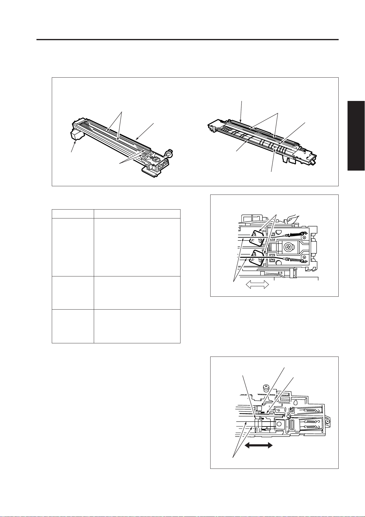
[5] M23 (Charger Cleaning ) Control
M23 CONT
5VDC
PS41
PS42
PS41
SGND
PS42
M23 F/R
M23 EM
PRCB
12VDC
5VDC
SGND
DCPS1
M23 (charger cleaning ) is a 12V DC motor which is
controlled by the PRCB (printer control board) via the
DCDB (DC drive board). Related signals are PS41
(charging wire cleaning pad HP ) and PS42 (charging
wire cleaning pad limit).
1. Operation
a. Purpose of driving
M23 is used to drive the charging wire cleaning
pad.
b. Operation timing
The charging corona wires are cleaned when the
main switch is turned ON, when the fixing
temperature is lower than 50°C (122°F). They
are also cleaned when the specified copy count
is reached.
* Changeable with 25 mode DIPSW
c. Cleaning operation
The home position of the charging wire cleaning
pad is on the rear side of machine. The charging
wire cleaning pad operates as follows:
M23
DRIVE1
M23
DRIVE2
DCDB
M23
2 - F - 4
Charging wire cleaning
pad HP PS
PS41 PS42
Cleaning (forward)
Cleaning (return)
Home search (forward)
Home search (return)
Charging wire cleaning
pad limit PS
Page 26

CORONA UNIT SECTION
2. Signals
a. PRCB input signals
(1) M23 EM (DCDB to PRCB)
M23 rotation state detection signal.
[L]: Normal rotation.
[H]: Abnormal rotation
(2) PS41 (PS41 to PRCB)
Charging wire cleaning pad home position
detection signal.
This signal detects the reference position (rear
side) of the charging wire cleaning pad home
position.
[L]: HP detected
[H]: HP not detected
(3) PS42 (PS42 to PRCB)
Charging wire cleaning pad limit detection signal.
This signal detects the front drive limit position
of charging wire cleaning pad.
[L]: Limit position detected
[H]: Limit position not detected
b. CB output signals
(1) M23 CONT (PRCB to DCDB)
M23 drive control signal.
[L]: M23 ON
[H]: M23 OFF
(2) M23 F/R (PRCB to DCDB)
M23 rotational direction signal.
[L]: CW (to the rear end from the home position)
[H]: CCW (to the home position from the rear
end)
c. DCDB output signal
(1) M23 DRIVE1, 2 (DCDB to M23)
M23 drive control signal.
The drive direction of M23 is controlled by
switching the drive current directions of two
signals.
Status
Forward stroke
of cleaning
Return stroke of
cleaning
Stop
M23 DRIVE1 M23 DRIVE2
HL
LH
LL
[6] M18 (Transfer/Separation Cleaning)
Control
M18
DRIVE1
DRIVE2
24VDC
PGND
DCPS2
PRCB
5VDC
SGND
DCPS1
MS2 MS1
5VDC
PS11
SGND
PS12
ADUSDB
M18 (transfer/separation cleaning) is a 24 VDC motor
which is controlled by the PRCB (printer control board)
via the ADUSDB (ADU stand drive board). Between
the PRCB and ADUSDB, signals are exchanged using
serial data. Related signals are PS11 (transfer/
separation wire cleaning pad HP) and PS12 (transfer/
separation wire cleaning pad limit). When the front right
or left door of this machine opens or closes, MS1
(interlock 1) or MS2 (interlock 2) operates to interrupt
the DC power supply to DCDB, stopping the voltage
supply to M18.
1. Operation
a. Purpose of driving
M8 is used to drive the transfer and separation
wire cleaning pads.
b. Operation timing
The transfer and separation wires are cleaned
when the main switch is turned ON, when the
fixing temperature is lower than 50°C, or when
the specified copy count is reached.
* Changeable with 25 mode DIPSW.
M18
M18
PS11
PS12
2 UNIT EXPLANATION
2 - F - 5
Page 27

CORONA UNIT SECTION
c. Cleaning operation
The home position of the transfer and separation
wire cleaning pads is on the front side of machine. The transfer and separation wire cleaning pads operate as follows:
Tansfer/Separation wire
cleaning pad HP
PS11 PS12
Cleaning (forward)
2 UNIT EXPLANATION
Cleaning (return)
Home search (forward)
Home search (return)
2. Signals
a. PRCB input signals
(1) PS11 (PS11 to PRCB)
T ransf er and separation wire cleaning pads home
position detection signal.
This signal detects the reference position of the
transfer and separation wire cleaning pads home
position (front side).
[L]: HP detected
[H]: HP not detected
(2) PS12 (PS12 to PRCB)
T ransf er and separation wire cleaning pads drive
limit detection signal.
This signal detects the rear limit position of the
transfer and separation wire cleaning pads.
[L]: Limit position detected
[H]: Limit position not detected
b. ADUSDB output signals
(1) M18 DRIVE1, 2 (ADUSDB to M18)
M18 drive control signal.
The drive direction of M18 is controlled by
switching the drive current directions of two
signals.
Tansfer/Separation wire
cleaning pad limit
[7] PCL/TSL Control
24VDC
PGND
DCPS2
PCL CONT
PRCB
LEDs are used for PCL (pre-charging lamp) and TSL
(transfer synchronization lamp). PCL is driven by the
DCDB (DC drive board). TSL is driven b y the ADUSDB
(ADU stand drive board). PCL and TSL are controlled
by the PRCB (printer control board).
1. Operation
PCL is turned ON/OFF in sync with M2 (drum
drive). TSL turns ON after a lapse of specified
time from turning ON of PS45 (leading edge
detection) of the second paper feed section. It
turns OFF after a lapse of specified time from
detection of the trailing edge of copy paper.
2. Signals
a. Output signals
(1) PCL CONT (PRCB to DCDB to PCL)
PCL ON/OFF control signal.
[L]: PCL ON
[H]: PCL OFF
(2) TSL CONT (ADUSDB to TLS)
TSL ON/OFF control signal.
[L]: TSL ON
[H]: TSL OFF
24VDC
PCL CONT
DCDB
24VDC
TSL CONT
ADUSDB
PCL
TSL
Status
Forward stroke
of cleaning
Return stroke of
cleaning
Stop
M18 DRIVE1 M18 DRIVE2
HL
LH
LL
2 - F - 6
Page 28
DEVELOPING UNIT
[1] Composition
Developing unit cover
Developing sleeve
Splash prevention
sheet (upper)
Developing regulation plate
Developing
sleeve
Agitator
wheel
DEVELOPING UNIT
Agitator screws
[2] Mechanisms
Mechanism Method
Developing 2-component developer
Developing bias DC bias
Developer Main agitator
agitation Auxiliary agitator
1. The developing unit drive motor (M3)
drives the following parts via the gear unit
at the back:
• Developing sleeve
• Agitator wheel
• Agitator screws
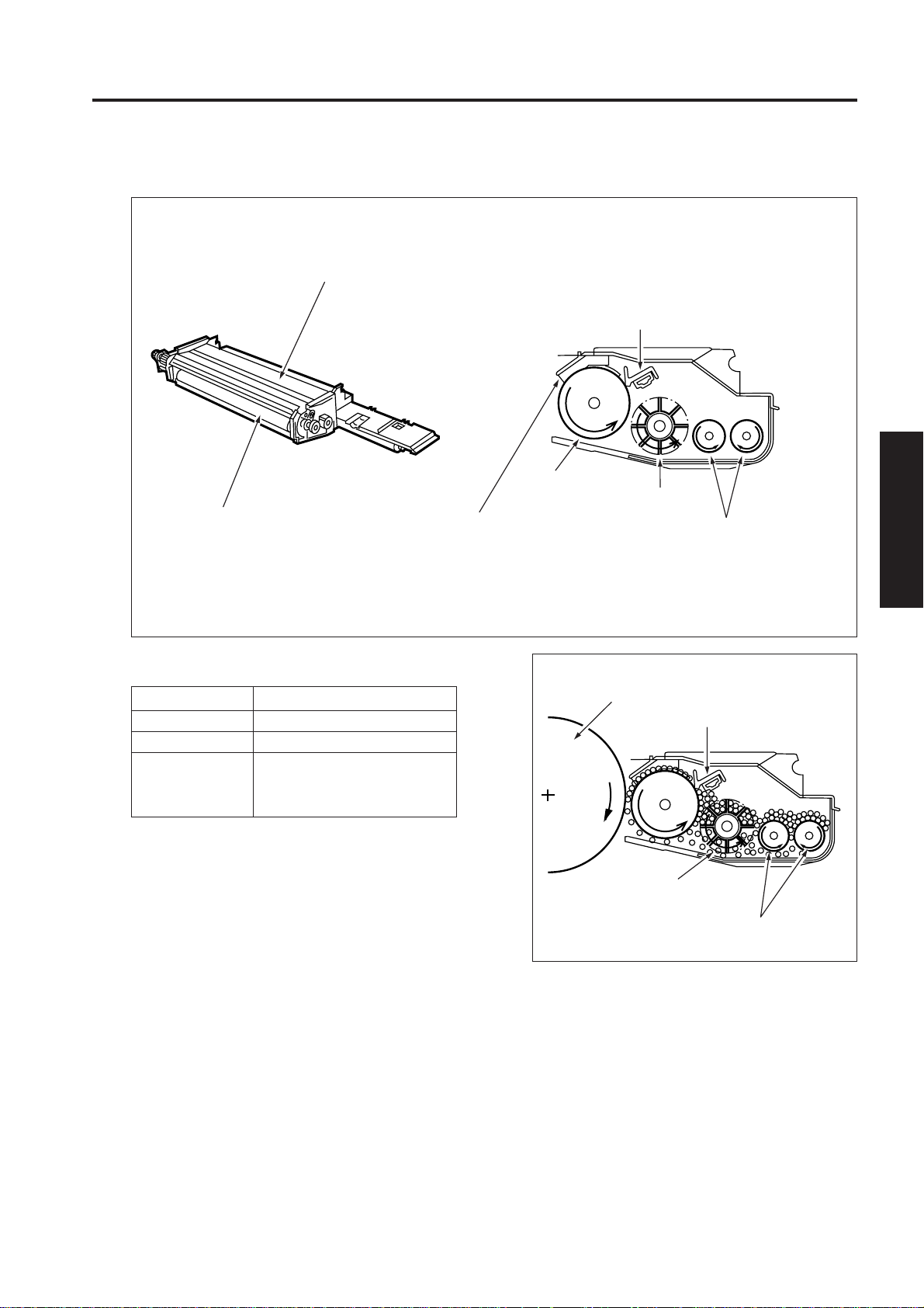
2. Flow of developer
The developer inside the developing unit is
supplied to the developing sleeve by the agitator
wheel, and maintained at a constant thickness
by the developing regulation plate (bristle height
regulation plate). The dev eloper remaining on the
developing sleeve is returned to the agitator
screws.
2 UNIT EXPLANATION
Drum
Developing regulation plate
Agitator wheel
Agitator screw
2 - G - 1
Page 29
DEVELOPING UNIT
[3] M3 (Developing Unit Drive) Control
24VDC
PGND
DCPS2
M3 CONT
M3 CLK
M3 EM
PRCB
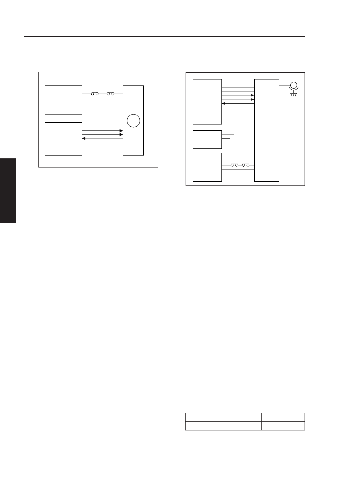
M3 (developing) is controlled by the PRCB (printer
control board) and the motor drive power is supplied
by DCPS2 (DC power supply unit 2). When the front
left or right door of this machine opens or closes, MS1
(interlock 1) or MS2 (interlock 2) operates to interrupt
the DC power supply to M3, stopping the voltage
2 UNIT EXPLANATION
supply to the developing sleeve.
MS2 MS1
M3
[4] Developing Bias Control
24VDC
5VDC
SGND
B CONT
B SHIFT
B FB
PRCB
5VDC
SGND
DCPS1
24VDC
24VDC
PGND
DCPS2
MS2 MS1
HV1
The developing bias is controlled by PRCB (printer
control board) via the HV1(high voltage unit 1). When
the front left or right door of this machine opens or
closes, MS1 (interlock 1) or MS2 (interlock 2) operates
to interrupt the DC power supply to HV1, stopping the
voltage supply to the developing sleeve.
BIAS
1. Operation
M3 which is the 24V driven DC motor drives the
developing slee ve and agitator . M3 equipped with
speed control circuit send the rotation error signal
to PRCB when PLL lock is released longer than
the specified time period. M3 starts after the
specified time interval from the start switch is ON,
and stops after the specified time interval from
the charging wire unit stops charging.
2. Signals
a. Input signals
(1) M3 EM (M3 to PRCB)
M3 fault detection signal
[H] Abnormal rotation (when PLL is unlocked
for more than 1.5 seconds)
[L] Normal rotation
b. Output signals
(1) M3 CONT (PRCB to M3)
M3 drive control signal
[L] M3 ON
[H] M3 OFF
1. Operation
The developing bias voltage is applied to the
developing sleeve based on the M2 (drum)
rotation state signal.
2. Signals
a. Input signals
(1) B FB (HV1 to PRCB)
Developing bias voltage feedback signal.
This signal monitors the developing bias v oltage.
It is an 0V to 5V analog signal corresponding to
the output level.
b. Output signals
(1) B CONT (PRCB to HV1)
Developing bias output ON/OFF control signal.
[L]: Developing bias ON
[H]: Developing bias OFF
(2) B SHIFT (PRCB to HV1)
Developing bias output level control signal.
The developing bias output level is controlled
according to the duty ratio of the pulse (PWM)
signal sent from the PRCB.
B SHIFT duty 20% to 80%
Developing bias output range -300 V to-800 V
2 - G - 2
Page 30

DEVELOPING UNIT
[5] Toner Density Control
24VDC
24VDC
M11 CLK
M11 RES
M11 VREF
M11 FEM
PRCB DCDB
24VDC
PGND
DCPS2
Toner density is controlled by controlling M11 (toner
supply 1) by PRCB (printer control board) via DCDB
(DC drive board). When the front right or left door of
this machine opens or closes, MS1 (interlock 1) or MS2
(interlock 2) operates to interrupt the DC power supply
to the motor, stopping the M15.
24VDC
24VDC
M11 DRIVE A
M11 DRIVE A
M11 DRIVE B
M11 DRIVE B
MS2 MS1
M11
2. Signals
a. PRCB input signal
(1) M11 FEM (DCDB to PRCB)
Signal detecting whether the fuse for M11 is
blown.
[L]: Not detected
[H]: Detected
b. PRCB output signals
(1) M11 CLK (PRCB to DCDB)
Reference clock signal f or M11 rotational speed
control.
(2) M11 RES (PRCB to DCDB)
M11 reset signal.
(3) M11 VREF (PRCB to DCDB)
M11 current control signal.
c. DCDB output signals
(1) M11 DRIVE A, A (DCDB to M11)
M11 A-phase drive signal.
(2) M11 DRIVE B, B (DCDB to M11)
M11 B-phase drive signal.
2 UNIT EXPLANATION
1. Operation
a. Toner density detection
The toner density detection sensor detects the
density of toner concentration in the developing
unit using a patch detection method, and outputs the corresponding analog voltage signal to
the PRCB.
The PRCB compares the detected voltage with
the reference value to determine whether toner
must be added.
b. Toner supply operation
Upon read of the patch, M11 is turned on to supply toner. The time needed to add toner depends
on the paper size.
2 - G - 3
Page 31

DEVELOPING UNIT
[6] Dmax Control
2 UNIT EXPLANATION
24VDC
24VDC
DCPS2
12VDC
DCPS1
PGND
5VDC
SGND
MS2 MS1
DRUM TEMP
Dmax LED CONT
Dmax LED Vref
JAM LED CONT
PRCB
M2 CONT
M2 F/R
SGND
M2 EM
M3 CONT
M3 CLK
M3 EM
DPS ANG
AGND
12VDC
5VDC
AGND
5VDC
Dmax SIG
Dmax MONI
JAM SIG
M2
M3
DPS DRIVE A
DPS DRIVE B
DPS ANG 1
DPS ANG 2
DPSB
TH5 ANG1
TH5 ANG2
DTSB
TCSB
DPS
TH5
Dmax control is performed by the TCSB (toner control
sensor board), M2 (drum), M3 (developing), and so
on. These par ts are controlled by the PRCB (printer
control board). Related boards and sensors are a
DPSB (drum potential sensor board), DPS (drum
potential sensor), DTSB (drum temperature sensor
board), and TH5 (drum temperature sensor).
When the front right or left door of this machine opens
or closes, MS1 (interlock 1) or MS2 (interlock 2)
operates to interrupt the DC power supply to the motor ,
stopping the M2 and M3.
1. Operation
The purpose of Dmax control is to adjust the
maximum density to the reference lev el for each
machine.
a. Dmax control
(1) Method
Latent images are created several times at the
maximum exposure lev el, images are dev eloped
with the rotational speed of the developing sleeve
varied, then each density is read by the Dmax
sensor (PD1) on the TSCB.
The developing sleeve speed detected when the
density has reached the reference level is
recorded as the optimum sleeve speed and the
developing is performed at this optimum sleeve
rotation speed.
(2) Timing
a) When the fixing temperature is lower than 50°C
at power ON
b) At the end of job after every 20,000 copies.
2 - G - 4
Page 32

2. Signals
a. PRCB input signals
(1) Dmax SIG (TCSB to PRCB)
Output voltage of the Dmax value detection
sensor (PD1) on the TCSB.
Reference voltage: 2.5V
(2) Dmax MONI (TCSB to PRCB)
This signal monitors the light reflected by the
drum surface (without toner).
The voltage applied to the Dmax detection LED
is corrected by γ/Dmax LED Vref so that the
output voltage becomes 4V (calibration).
Reference voltage: 4V
<Timing->
a) Before D max correction.
(3) JAM SIG (ITCSB to PRCB)
This signal detects a jam caused by paper
wrapping around the drum. A jam is detected
when the voltage becomes 4.0V or more.
[L]: LED ON
[H]: LED OFF
b. Output signals
(1) Dmax LED CONT (PRCB to TCSB)
This signal turns ON/OFF the D max LED.
(2) Dmax LED Vref (PRCB to TCSB)
Power supply line for PD1 LED on TSCB.
The voltage is adjusted so as the Dmax MONI
signal to be 4 V.
(3) JAM LED CONT (PRCB to TCSB)
This signal turns ON/OFF the JAM LED.
[L]: LED ON
[H]: LED OFF
DEVELOPING UNIT
2 UNIT EXPLANATION
2 - G - 5
Page 33

DEVELOPING UNIT
[7] Gradation Correction Control
2 UNIT EXPLANATION
24VDC
24VDC
DCPS2
12VDC
DCPS1
PGND
5VDC
SGND
MS2 MS1
/Dmax LED Vref
PRCB
M2 CONT
M2 F/R
SGND
M2 EM
M3 CONT
M3 CLK
M3 EM
DPS ANG
AGND
5VDC
LED CONT
SIG/MONI
M2
M3
DPS DRIVE A
DPS DRIVE B
DPS ANG 1
DPS ANG 2
DPSB
TCSB
DPS
Gradation correction control is performed by the TCSB
(toner control sensor board), M2 (drum), M3
(developing), and so on. These parts are controlled
by the PRCB (printer control board).
1. Operation
The gradation characteristics of the toner density
versus exposure amount at the image forming
section (drum area) are detected to obtain a linear
relation between the image density on a
document and the copying image density (toner
density).
(1) Method
Exposure is performed with the laser PWM varied
in several steps, and development is performed
at the toner transfer sleeve speed obtained by
Dmax correction.
Next, each density is read by γ sensor (PD2) on
the TCSB to detect the gradation char acteristics
of image density.
The gradation characteristics obtained here are
used as the values for correcting the laser
exposure amount.
(2) Timing
a) When the fixing temperature is lower than 50°C
at power ON
b) At the end of job after every 20,000 copies.
2. Signals
a. PRCB Input signals
(1) γ SIG/MONI (TCSB to PRCB)
Output voltage from the γ sensor (PD2) on the
TCSB. This signal monitors the light reflected
by the drum surface (without toner).
The voltage applied to the gradation detection
LED is corrected by γ/Dmax LED Vref so that the
output voltage becomes 4.5V (calibration).
Reference voltage: 4.5V
<Timing>
Before gradation correction.
2 - G - 6
Page 34

DEVELOPING UNIT
b. PRCB Output signals
(1) γ LED CONT (PRCB to TCSB)
ON/OFF control signal for gradation detection
LED.
[L]: LED ON
[H]: LED OFF
(2) γ Dmax LED Vref (PRCB to TCSB)
Power supply line to the γ LED on the TCSB.
The voltage applied to the γ LED is adjusted so
that the γ MONI signal becomes 4.5V
[8] Dot Diameter Correction Control
5VDC
/Dmax LED Vref
LED CONT
SIG/MONI
PRCB TCSB
Dot diameter is detected by TCSB and controlled by
PRCB.
1. Operation
Dot diameter correction is performed to prevent
the fluctuation of 1 dot laser beam in diameter
due to a soil in the writing unit or a change of
developing ability.
(1) Method
Creates several same condensation dot pattern
patches changing the laser power and reads
them with γ sensor (PD2). Uses the laser power
where the γ sensor output reaches reference
voltage as MPC.
(2) Timing
a) At the end of job after every 20,000 copies.
2 UNIT EXPLANATION
2 - G - 7
Page 35

DEVELOPING UNIT
[9] FM2 (Developing Suction) Control
FM2 CONT
FM2 EM
FM2 FEM
PRCB
24VDC
PGND
DCPS2 ACDB
FM2 (Developing suction) is controlled by the PRCB
2 UNIT EXPLANATION
(printer control board) via the ACDB (AC drive board).
When the front right or left door of this machine opens
or closes, MS1 (interlock 1) or MS2 (interlock 2)
operates to interrupt the DC power supply, stopping
FM2.
1. Operation
a. ON timing
During idling: FM2 turns when M2 (drum) turns
ON.
During copying: FM2 turns when M1 (main) turns
ON.
b. OFF timing
During idling: FM2 turns OFF when M2 turns OFF
or in the specified interval after completion of
copying.
During copying: Always ON.
MS2 MS1
FM2 DRIVE
FM2 EM
PGND
FM2
b. PRCB output signals
(1) FM2 CONT (PRCB to ACDB)
FM2 control signal.
[L]: FM2 ON
[H]: FM2 OFF
c. ACDB output signal
(1) FM2 DRIVE (ACDB to FM2)
FM2 drive signal
[L]: FM2 OFF
[H]: FM2 ON
2. Signals
a. PRCB input signals (ACDB to PRCB)
(1) FM2 EM (FM2 to ACDB to PRCB)
FM2 fault detection signal.
[L]: FM2 is normal.
[H]: FM2 is abnormal.
(2) FM2 FEM (ACDB to PRCB)
Signal detecting whether the 24V fuse for FM2 is
blown.
[L]: Blown fuse is not detected.
[H]: Blown fuse is detected.
2 - G - 8
Page 36

TONER SUPPLY UNIT
[1] Composition
Toner supply
motor 1 (M11)
TONER SUPPLY UNIT
Toner cartridge
2 UNIT EXPLANATION
Push pressure lever
Toner supply
motor 2 (M15)
[2] Mechanisms
Mechanism Method
Toner supply Supply by screw
Toner level detection Piezoelectric method
130±30 g
*1 Toner agitation Agitator plates
*2 Toner cartridge Rotary cartridge
Capacity: 1700 g
Toner leakage Toner supply shutter
prevention
*1 Toner agitation
Toner agitator plates are driven by the following
two motors through the gear unit:
a. Toner supply motor 1 (M11): Drives the toner
supply screw.
b. Toner supply motor 2 (M15): Drives the toner
cartridge.
The agitator plates rotate faster when toner supply
motor 1 (M11) runs than when toner supply motor 2
(M15) runs. When the two motors are running
simultaneously, the one-way clutch installed on the
agitator shaft selects toner supply motor 2 (M15).
Shutter
The agitator plates prevent the toner from clumping
and accumulating on TLD (remaining toner detection
sensor).
Toner supply motor 1 (M11)
Toner supply motor 2 (M15)
Toner cartridge
Agitator plate
Toner supply screw
One way clutch
2 - H - 1
Page 37

TONER SUPPLY UNIT
*2 Toner cartridge
When the toner cartridge rotates, toner is fed to
the outlet of the cartridge through the spiral
groove on the surf ace of the toner cartridge. When
the outlet of the cartridge faces downward, toner
flows out of the outlet into the agitation/supply
section of the toner supply unit.
2 UNIT EXPLANATION
90° rotation
Outlet
A
C
C
To agitation/conveyance
block of toner supply unit
B
B
A
[3] Toner Level Detection Control
24VDC
PGND
DCPS2
M15 CONT
M15 EM
TLD CONT
TLD
SGND
PRCB DCPS1
Toner level detection is controlled by the TLD (toner
level detection sensor) and the PRCB (printer control
board).
12VDC
SGND
M15
TLD
1. Operation
a. Toner level detection
A piezoelectric device is used as the TLD.
When the level of toner in the cartridge becomes
low , the toner supply signal is output to the PRCB.
As a result, a message is displayed on the LCD
connected to the OB1 (operation board 1).
b. Detection timing
The detection timing is as follows:
• Power-on
• When the front door opens or closes
• During copying
c. Toner supply to toner supply unit
When the no toner state is detected by TLD, M15
(toner supply 2) is turned ON to supply toner from
the toner cartridge to the toner supply unit.
d. Detection of no toner state in toner cartridge
If the no toner state is detected by TLD after M15
has been held ON for a specified period of time,
the toner cartridge is assumed to be empty.
2 - H - 2
Page 38

2. Signals
a. Input signal
(1) TLD (TLD to PRCB)
When the level of toner in the cartridge becomes
low , this signal goes low [L], displaying a message
on the LCD connected to the OB1.
(2) M15 EM (M15 to PRCB)
M15 fault detection signal.
[L]: M15 normal
[H]: M15 Abnormal
a. Output signals
(1) TLD CONT (PRCB to TLD)
TLD power control signal.
The TLD is pow ered only when it is detecting the
toner level.
(2) M15 CONT (PRCB to M15)
M15 control signal
[L]: M15 ON
[H]: M15 OFF
TONER SUPPLY UNIT
2 UNIT EXPLANATION
2 - H - 3
Page 39

TONER SUPPLY UNIT
[4] M11 (Toner Supply 1) Control
/Dmax LED Vref
Dmax LED CONT
2 UNIT EXPLANATION
M11 (Toner Supply 1) is controlled by the PRCB
(printer control board) via the DCDB (DC drive board).
The toner density is detected by TCSB(toner control
sensor board).
When the front right or left door of this machine opens
or closes, MS1 (interlock 1) or MS2 (interlock 2)
operates to interrupt the DC power supply to the motor ,
stopping M11.
5VDC
Dmax SIG
TCSB
24VDC
24VDC
M11 CLK
M11 RES
M11 VREF
M11 FEM
24VDC
24VDC
M11 DRIVE A
M11 DRIVE A
M11 DRIVE B
M11 DRIVE B
PRCB DCDB
24VDC
PGND
MS2 MS1
DCPS2
M11
Paper size Supply time (sec.)
A3 1.14
B4 0.86
F4 0.86
A4 0.57
A4R 0.57
B5 0.43
B5R 0.43
A5 0.29
A6 0.22
1. Operation
a. Detection of toner density
The Dmax sensor (PD1) mounted on the TCSB
detects the density of the toner control chart to
output the signal corresponding to the detected
density to the PRCB.
b. Toner supply
When the voltage detected by the TCSB is below
the specified value, the PRCB issues a control
signal to drive the M11. The relationship between
the paper size and toner supply time is
summarized in the following table:
2 - H - 4
Page 40

CLEANING/TONER RECYCLE UNIT
[1] Composition
Blade drive motor (M14)
Blade 2
CLEANING/TONER RECYCLE UNIT
[2] Mechanisms
Mechanism
*1 Drum cleaning
Toner collection
*2 Toner recycle
*1 Drum cleaning
T w o cleaning blades are installed in the cleaning
section. When the blade motor (M14) rotates, the
blade release arm is pressed down. At the same
time, the cleaning blade drive shaft with two
cleaning blades 1 and 2 is turned by the wire
wound around the shaft, thereby switching
between blades 1 and 2 automatically, increasing the usable life of the blades.
Cleaning blades
(switched automatically)
Toner guide brush
Toner conveyance by
screw
Method
Blade 1
Toner guide brush
Vibration sheet
Toner conveyance screw
Blade release arm
Blade 2
Toner guide shaft
Blade 1
2 UNIT EXPLANATION
*2 Toner collection
T oner remov ed by the cleaning blade is collected
by the toner guide brush to be reused.
2 - I - 1
Page 41

CLEANING/TONER RECYCLE UNIT
[3] M14 (Blade) Control
5VDC
PS30
SGND
PS30
PS31
M14 PL
M14 NL
2 UNIT EXPLANATION
M14 PR
M14 NR
M14 CEM
M14 24FEM
PRCB
24VDC
PGND
DCPS2
M14 (cleaning blade) is a 24V DC driven motor and
drives the cleaning blades. By M14, the cleaning blade
contacts on the drum surface slight pressing or
pressing to clean the drum surface. These two blades
are automatically switched by M14. M14 is controlled
by PRCB (printer control board) through DCDB (DC
drive board). Related signals are PS30 (blade 1) and
PS31 (blade 2).
1. Operation
M14 turns ON/OFF in synchronized with ON/OFF
of M2(drum).
The blade is controlled (pressing, slight pressing,
and switching) by PS30 and PS31 detecting the
blade position, and M14 rotaing forward and
backward.
The following table shows the relationship
between PS30/PS31 and blade position.
PS31
M14 DRIVE 1
M14 DRIVE 2
M14
DCDB
5VDC
SGND
DCPS1
MS2 MS1
Sensor Blade Position
Pressing CW/ Slight CW/ Switching
CCW pressing CCW
PS30 OFF OFF ON or OFF*ON ON
PS31 ON OFF OFF OFF ON
*Note: CW/CCW indicate the M14 rotating
direction for pressing, slight pressing, and
switching. The sensor logic for slight
pressing position is different between CW
and CCW rotation.
CCW: ON
CW: OFF
2 - I - 2
Page 42

a. Blade auto switching control
This unit uses two blades with M14 rotating to
automatically replace blades. During automatic
blade replacement, M2 (drum), M3 (developing),
developing bias, guide plate voltage, and PCL
are turned ON, toner is adhered to the drum, and
then the blade cleans it to prevent blade peeling.
<Timing>
a) At the end of job after every 20,000 copies.
b. Blade setting mode
Blade setting mode is available in 36 mode as a
task after blade replacement during maintenance.
Blade setting mode adheres toner on drum as in
blade auto replacement control and then the
blade cleans toner to prevent blade peeling.
c. Black stripe creation control
In order to improve durability of the b lade (stabilize load, prevent paper dust crushing), a black
stripe toner is adhered on drum once every ten
copies and then cleaned.
*Changeable with 25 mode DIPSW.
CLEANING/TONER RECYCLE UNIT
2 UNIT EXPLANATION
2. Signals
a. PRCB input signal
(1) PS30 (PS30 to PRCB)
Blade position detection signal 1
(2) PS31(PS31 to PRCB)
Blade position detection signal 2
(3) M14 CEM
M14 error detection signal
[L]: Normal
[H]: Error
(4) M14 24FEM
M14 blown fuse detection signal
[L]: Not detected
[H]: Detected
b. PRCB output signal
(1) M14 PL,NL,PR,NR(PRCB to DCDB)
M14 drive control signal
c. DCDB output signal
(1) M14 DRIVE 1,2 (DCDB to M14)
M14 drive control signal
2 - I - 3
Page 43

TRAY 1/2 PAPER FEED UNIT
[1] Composition
TRAY 1/2 PAPER FEED UNIT
Side guides
Trailing edge stopper
Wire B
Paper size detection VR1,2
Paper size detection PS1-1, 2-1(PS32, PS33)
Paper size detection PS1-2, 2-2(PS35, PS36)
Caution: Trays 1 and 2 have the same shape
and mechanisms.
Feed roller
Paper feed roller
Double feed prevention roller
Drive pulley
2 UNIT EXPLANATION
Wire A
Up drive motor1(M19), 2(M20)
[2] Mechanisms
Mechanism
*1 Paper lift-up
Tray loading
Double feed prevention
*2 1st paper feed
No paper detection
*3 Paper size detection (Universal)
*1 Paper lift-up
a. Hoisting of up/down plate
The up/down plate is lifted up by up/down wires. When the paper tray is loaded, the up drive motor
1(M19), 2(M20) rotates to wind the up/down wires around the drive pulleys and consequently the plate
moves up and push up papers set in the tray. When the tray upper limit PS1(PS20), 2(PS21) detects the
actuator of the plate that has moved up, the up drive motor 1(M19), 2(M20) stops.
Method
Up: Paper up/down plate driven by up/down wires
Down: Falls down by its own weight
Load from the front door side
Torque limiter
Paper feed roller
Pick up solenoid 1(SD8), 2(SD9)
Photosensor + Actuator
Width: VR
Length: Photosensor + Actuators (two)
2 - J - 1
Page 44

TRAY 1/2 PAPER FEED UNIT
b. Lowering of up/down plate
When the paper feed tray is pulled out, the
guide lever shown below is disengaged from
the rail, thus releasing the coupling gear that
transmits the drive force of the up drive motor
1(M19), 2(M20) to the drive pulleys. Then, the
up/down plate falls down naturally by the
weight of papers.
2 UNIT EXPLANATION
*2 1st paper feed
To keep a constant contact pressure on the paper by the paper feed roller at the time of paper
pick-up, the weight of the paper feed roller itself
is used. The pick up solenoid 1(SD8), 2(SD9)
moves the paper feed swivel plate down so that
the paper feed roller mounted on the plate falls
down to touch the paper as well. Then, the paper feed roller picks up a paper and feeds it
toward the paper conv eyance unit. The first paper
feed solenoid moves the paper feed swivel plate
down only when paper is to be fed. Otherwise, it
releases contact.
Coupling gear
Up drive motor
1(M19), 2(M20)
Guide lever
Paper feed swivel plate
Tray insertion
direction
*3 Paper size detection
Length: The rear guide of the tray moves,
causing the paper size detection
actuator to move as well. As a result,
the two paper size detection PS1-1, 21(PS32, PS33), 1-2, 2-2 (PS35, PS36)
turn ON and/or OFF. Thus, the paper
size is automatically determined
according to the combination of the ON/
OFF states of these PSs.
Width: The side guide of the tray moves, caus-
ing the side guide (front) rack gear of
the paper size detection arm to turn the
gear of the paper size detection VR1,
2. Thus, the paper siz e is automatically
determined according to the change in
the resistance value of the VR.
Paper size
detection
PS1-1, 2-1
(PS32, PS33)
1-2, 2-2 (PS35, PS36)
Actuator
Rack gear
Feed roller
Feed roller
Pick up SD
1(SD8), 2(SD9)
Side guide (front)
Paper size VR gear
2 - J - 2
Page 45

[3] First Paper Feed Control
TRAY 1/2 PAPER FEED UNIT
24VDC
PGND
M4
PS47
PS48
PS49
PS50
M4 CONT
M4 EM
SVDC
PS47
SGND
PS48
SVDC
PS49
SGND
PS50
MC3 CONT
MC4 CONT
SD8 CONT
MC5 CONT
MC6 CONT
SD9 CONT
PRCB DCDB
5VDC
SGND
DCPS1
MC3 CONT
MC4 CONT
SD8 CONT
MC5 CONT
MC6 CONT
SD9 CONT
24VDC
24VDC
2 UNIT EXPLANATION
MC3
MC4
SD8
MC5
MC6
SD9
The 1st paper feed from tray 1 or 2 takes place as the
result of the transmission of the drive force from M4
(paper feed) to each paper feed roller, via MC3 (feed
MC 1), MC5 (feed MC 2), and MC4 (pre-registration
MC1), MC6 (pre-registration MC 2). SD8 (pickup SD1)
or SD9 (pickup SD 2) causes the roller to pick up paper .
The above operations are controlled by the PRCB
(printer control board). Related signals are PS47
(paper feed1), PS49 (paper feed 2), PS48 (preregistration 1), and PS50 (paper pre-registration 2).
1. Operation
a. First paper feed timing (feed clutch drive)
(1) When printing of the first copy starts:
Timing that is determined by the P counter from
when copying starts
(2) When printing of the second copy starts:
When PS47 or PS49 turns OFF
(3) OFF timing
After a specified count from PS48, and PS50
turns ON (adjustable)
*Changeable in 36 mode
b. Feed timing (pre-registration clutch drive)
(1) ON timing
When a drive signal is received from PRCB
(2) OFF timing
When PS47 or PS49 is turned OFF.
2 - J - 3
Page 46

TRAY 1/2 PAPER FEED UNIT
2. Signals
a. PRCB input signals
(1) PS47 (PS47 to PRCB)
Paper passage detection signal (tray 1).
[L]: Paper passed.
[H]: Paper not passed.
(2) PS49 (PS49 to PRCB)
Paper passage detection signal (tray 2).
[L]: Paper passed.
[H]: Paper not passed.
(3) PS48 (PS48 to PRCB)
First paper feed paper detection signal (tray 1).
2 UNIT EXPLANATION
[L]: Paper exists.
[H]: Paper does not exist.
(4) PS50 (PS50 to PRCB)
First paper feed paper detection signal (tray 2).
[L]: Paper exists.
[H]: Paper does not exist.
b. PRCB output signals
(1) MC3 CONT (PRCB to DCDB to MC3)
MC3 drive control signal (tray 1).
[L]: MC3 ON
[H]: MC3 OFF
(2) MC5 CONT (PRCB to DCDB to MC5)
MC5 drive control signal (tray 2).
[L]: MC5 ON
[H]: MC5 OFF
(3) MC4 CONT (PRCB to DCDB to MC4)
MC4 drive control signal (tray 1.)
[L]: MC4 ON
[H]: MC4 OFF
(4) MC6 CONT (PRCB to DCDB to MC6)
MC6 drive control signal (tray 2)
[L]: MC6 ON
[H]: MC6 OFF
(5) SD8 CONT (PRCB to DCDB to SD8)
SD8 drive control signal (tray 1)
[L]: SD8 ON
[H]: SD8 OFF
(6) SD9 CONT (PRCB to DCDB to SD9)
SD9 drive control signal (tray 2)
[L]: SD9 ON
[H]: SD9 OFF
2 - J - 4
Page 47

[4] Paper Up Drive Control
TRAY 1/2 PAPER FEED UNIT
5VDC
PS14
PS20
PS34 PS34
PS15
PS21
PS37 PS37
PS14
SGND
PS20
5VDC
PS15
SGND
PS21
5VDC
SGND
DCPS1
DCPS2
M19 CONT
M19 EM
M19 FEM
SD5 CONT
M20 CONT
M20 EM
M20 FEM
SD6 CONT
M19 CONT
SD5 CONT
M20 CONT
SD6 CONT
PRCB DCDB
24VDC
PGND
24VDC
24VDC
24VDC
24VDC
2 UNIT EXPLANATION
M19
SD5
M20
SD6
Papers stacked in the tray are pushed up by
transmitting the drive force of M19 (up drive 1) or M20
(up drive 2) to the paper up/down plate in the tray via
up/down wires. M19 and M20 are controlled by the
PRCB (printer control board) via the DCDB (DC drive
board). Related signals are PS20 (tray upper limit 1),
PS21 (tray upper limit 2), PS34 (remaining paper
detection 1), and PS37 (remaining paper detection 2).
To prevent pull-out of tray during copying operation
that cause paper jamming, a tray lock mechanism is
implemented by PS14 (handle release 1), PS15
(handle release 2), SD5 (lock SD1), and SD6 (lock
SD2).
1. Operation
a. Paper up drive control
When tray 1 or 2 is loaded, M19 or M20 goes
ON for a fixed time, raising the paper up/down
plate in the tray. When PS20 or PS21 detects
the upper limit of paper as the paper up/down
plate in the tray goes up, it goes ON and
consequently M19 or M20 goes OFF, stopping
raising the paper up/down plate. When PS20 or
PS21 goes OFF after a paper is fed, M19 or M20
goes ON again, moving the paper up/down plate
upward. The up/do wn plate in the tray is lowered
mechanically by its own weight.
b. Paper up drive timing
(1) ON timing
M19 or M20 is turned ON when loading of a tray
is detected (by shorting wires at both ends of the
drawer connector) or when PS26 or PS27 is
turned ON.
(2) OFF timing
M19 or M20 is turned OFF when PS20 or PS21
is turned ON.
2 - J - 5
Page 48

TRAY 1/2 PAPER FEED UNIT
c. Remaining Paper Detection
The level of paper remaining in each tray is detected according to the time that M19 or M20
requires to lift up the paper up/down plate when
the tray is set. This lift-up time (oper ation time of
M19 or M20) is recorded in the PRCB. Subsequently, remaining paper is detected by the paper feed counter . The detected remaining paper
level is displayed on the operation panel in 4
steps. PS34 and PS37 are used to detect the
remaining paper level when it lo wers below about
10%.
2 UNIT EXPLANATION
d. Tray lock control
When the tray handle is gripped, PS14 or PS15
is turned ON. This signal then causes SD5 or
SD6 to go ON, releasing the lock.
2. Signals
a. PRCB input signals
(1) PS14 (PS14 to PRCB)
Tray drawer handle detection signal (tray 1).
[L]: Detected
[H]: Not detected
(2) PS15 (PS15 to PRCB)
Tray drawer handle detection signal (tray 2).
[L]: Detected
[H]: Not detected
(3) PS20 (PS20 to PRCB)
Paper upper limit detection signal (tray 1).
[L]: Detected
[H]: Not detected
(4) PS21 (PS21 to PRCB)
Paper upper limit detection signal (tray 2).
[L]: Detected
[H]: Not detected
(5) PS34 (PS34 to PRCB)
Remaining paper detection signal (tray 1).
[L]: Detected
[H]: Not detected
(6) PS37 (PS37 to PRCB)
Remaining paper detection signal (tray 2).
[L]: Detected
[H]: Not detected
(7) M19 EM (DCDB to PRCB)
M19 fault (excessive current) detection signal
(tray 1).
[L]: Normal
[H]: Abnormal
(8) M19 FEM (DCDB to PRCB)
Signal indicating whether M19’s 24V fuse is
blown (tray 1)
[L]: Not detected
[H]: Detected
(9) M20 EM (DCDB to PRCB)
M20 fault (excessive current) detection signal
(tray 2)
[L]: Normal
[H]: Abnormal
(10)M20 FEM (DCDB to PRCB)
Signal indicating whether M20’s 24V fuse is b lown
(tray 2)
[L]: Not detected
[H]: Detected
b. PRCB output signals
(1) M19 CONT (PRCB to DCDB to M19)
M19 ON/OFF control signal (tray 1).
[L]: M19 ON
[H]: M19 OFF
(2) M20 CONT (PRCB to DCDB to M20)
M20 ON/OFF control signal (tray 2).
[L]: M20 ON
[H]: M20 OFF
(3) SD5 CONT (PRCB to DCDB to SD5)
SD5 drive control signal (tray 1).
[L]: SD5 ON
[H]: SD5 OFF
(4) SD6 CONT (PRCB to DCDB to SD6)
SD6 drive control signal (tray 2).
[L]: SD6 ON
[H]: SD6 OFF
2 - J - 6
Page 49

TRAY 1/2 PAPER FEED UNIT
[5] Paper Size Detection Control
5VDC
PS32
SGND
PS33
VR1
5VDC
PS35
SGND
PS36
VR2
PS32
PS33
PS35
PS36
5VDC
SGND
VR1
VR2
2. Signals
a. Input signals
(1) PS32 (PS32 to PRCB)
Paper size detection s witch ON/OFF signal (tra y
1)
(2) PS33 (PS33 to PRCB)
Paper size detection s witch ON/OFF signal (tra y
1)
(3) PS35 (PS35 to PRCB)
Paper size detection s witch ON/OFF signal (tra y
2)
(4) PS36 (PS36 to PRCB)
Paper size detection s witch ON/OFF signal (tra y
2)
(5) VR1 (VR1 to PRCB)
Paper width detection signal (tray 1)
(6) VR2 (VR2 to PRCB)
Paper width detection signal (tray 2)
2 UNIT EXPLANATION
PRCB DCPS1
The paper size in tray 1/2 is detected using PS32
(paper size 1-1), PS33 (paper size 2-1), PS35 (paper
size 1- 2), PS36 (paper size 2-2), paper size detection
VR1, and paper size detection VR2. Based on the
detection signals, the PRCB (printer control board)
judges the paper size.
1. Operation
The length of paper is detected using PS32,
PS33, PS35, and PS36. Variable resistors (VR1
and VR2) are installed at the bottom of the tray
to detect the width of paper.
The relationships between the switches and
paper sizes (lengths) are as follows:
Paper size
Switch
PS32 or PS35
PS33 or PS36
8.5 x 11 A4R to F4 8.5 x 14
or less B5R
OFF OFF ON ON
OFF ON ON OFF
or larger
2 - J - 7
Page 50

TRAY 1/2 PAPER FEED UNIT
[6] No paper detection control
5VDC
PS26
SGND
5VDC
PS27
SGND
PS26
PS27
2 UNIT EXPLANATION
PRCB DCPS1
5VDC
SGND
No paper in the tray is detected by PS26 (no paper 1)
and PS27 (no paper 2) which are controlled by the
PRCB (printer control board).
1. Operation
When the tray becomes empty, PS26 or PS27 is
turned ON, displaying a message on LCD via
the OB1 (operation board 1).
2. Signals
a. Input signals
(1) PS26 (PS26 to PRCB)
No paper detection signal (tray 1)
[L]: Paper does not exist in tray
[H]: Paper exists in tra y
2) PS27 (PS27 to PRCB)
No paper detection signal (tray 2)
[L]: Paper does not exist in tray
[H]: Paper exists in tra y
2 - J - 8
Page 51

TRAY 3 PAPER FEED UNIT
[1] Composition
Paper feed roller
Side guide
TRAY 3 PAPER FEED UNIT
Feed roller
Double feed prevention roller
Paper size detection
PS1-3(PS38), 2-3(PS39)
[2] Mechanisms
Mechanism
*1 Paper lift-up
Tray loading
Double feed prevention
*2 1st paper feed
Trailing edge stopper
Paper size
detection VR3
Method
Up: Paper up/down plate driven by up/down wires
Down: Falls down by its own weight
Front loading
Torque limiter
Paper feed roller
Pick up solenoid 3 (SD10)
Drive pulley
Front cover
2 UNIT EXPLANATION
Wire A
Wire B
Up drive motor 3 (M21)
No paper detection
*3 Paper size detection
(Universal)
*1 Paper lift-up
a. Hoisting of up/down plate
The up/down plate is lifted up by up/down wires. When the paper tray is loaded, the up drive motor 3
(M21) rotates to wind the up/down wires around the drive pulleys and consequently the plate moves up.
When the tray upper limit PS3 (PS22) detects the actuator of the plate that has moved up, the up drive
motor 3 (M21) stops.
Photosensor + Actuator
Width: VR
Length: Photosensor + Actuators (two)
2 - K - 1
Page 52

TRAY 3 PAPER FEED UNIT
b. Lowering of up/down plate
When the paper feed tray is pulled out, the guide
lever shown below is disengaged from the rail,
thus releasing the coupling gear that transmits
the drive force of the up drive motor 3(M21) to
the drive pulleys. Then, the up/down plate falls
down mechanically by the weight of papers.
2 UNIT EXPLANATION
Coupling gear
Up drive motor 3
(M21)
Guide lever
*3 Paper size detection
Length: The rear guide of the tray moves, causing the paper size detection actuator to move as
well. As a result, the two paper size detection
PS1-3 (PS38), 2-3 (PS39) turn ON and/or OFF.
Thus, the paper size is automatically determined
according to the combination of the ON/OFF
states of these PSs.
Width: The side guide of the tra y moves , causing
the side guide (front) rack gear to turn the gear
of the paper size detection VR3. Thus, the paper
size is automatically determined according to the
change in the resistance value of the VR.
Tray insertion
direction
Paper size detection
PS1-3(PS38),
2-3(PS39)
*2 1st paper feed
To keep constant contact pressure on the paper
by the paper feed roller at the time of paper pic kup, the weight of the paper feed roller itself is
used. The pick up solenoid 3(SD10) moves the
the paper feed swivel plate down so that the paper feed roller mounted on the plate falls down
to touch the paper as well. Then, the paper feed
roller picks up a paper and feeds it toward the
paper conveyance unit. The first paper feed solenoid moves the paper feed swivel plate down
only when paper is to be fed. Otherwise, it releases contact.
Paper feed swivel plate
Paper feed roller
Pick up solenoid
3(SD10)
Actuator
Rack gear
Side guide (front)
Paper size VR gear
Feed roller
2 - K - 2
Page 53

[3] First Paper Feed Control
TRAY 3 PAPER FEED UNIT
24VDC
PGND
M4
PS51
PS52
M4 CONT
M4 EM
5VDC
PS51
SGND
PS52
MC3 CONT
MC4 CONT
SD8 CONT
PRCB DCDB
The 1st paper feed from tray 3 takes place as the result
of the transmission of the drive force from M4 (paper
feed) to each paper feed roller, via MC7 (feed MC3)
and MC8 (pre-registration MC3). SD10 (pick up SD3)
causes the roller to pick up paper. The above
operations are controlled by the PRCB (printer control
board). Related signals are PS51 (paper feed 3), and
PS52 (paper pre-registration 3).
1. Operation
a. First paper feed timing (feed clutch drive)
(1) When printing of the first copy starts
Timing that is determined by the P counter from
when copying starts
(2) When printing of the second copy starts
When PS51 turns OFF after the first paper feed
detection
(3) OFF timing
After a specified count from PS50 turns ON
*Changeable in 36 mode
b. Feed timing (pre-registration clutch drive)
(1) ON timing
When a drive signal is received from PRCB
(2) OFF timing
When PS51 is turned OFF.
5VDC
SGND
DCPS1
24VDC
MC7 CONT
MC8 CONT
SD10 CONT
MC7
MC8
SD10
2. Signals
a. PRCB input signals
(1) PS51 (PS51 to PRCB)
Paper passage detection signal
[L]: Paper passed.
[H]: Paper not passed.
(2) PS52 (PS52 to PRCB)
First paper feed paper detection signal.
[L]: Paper exists.
[H]: Paper does not exist.
b. CB output signals
(1) MC7 CONT (PRCB to DCDB to MC7)
MC7 drive control signal (tray 1).
[L]: MC7 ON
[H]: MC7 OFF
(2) MC8 CONT (PRCB to DCDB to MC8)
MC8 drive control signal (tray 2).
[L]: MC8 ON
[H]: MC8 OFF
(3) SD10 CONT (PRCB to DCDB to SD10)
SD10 drive control signal (tray 1)
[L]: SD10 ON
[H]: SD10 OFF
2 UNIT EXPLANATION
2 - K - 3
Page 54

TRAY 3 PAPER FEED UNIT
[4] Paper Up Drive Control
5VDC
PS16
PS22
PS40
2 UNIT EXPLANATION
PS16
SGND
PS22
PS40
M21 CONT
M21 EM
M21 FEM
SD7 CONT
PRCB
Papers stacked in the tray are pushed up by
transmitting the drive force of M21 (up drive 3) to the
paper up/down plate in the tray via up/down wires.
M21 is controlled by the PRCB (printer control board)
via the DCDB (DC drive board). The related signals
are PS22 (tray upper limit 3) and PS40 (remaining
paper detection 3). To prevent pull-out of tray during
copying operation that cause paper jamming, a tray
lock mechanism is implemented by PS16 (handle
release 3) and SD7 (lock SD3).
1. Operation
a. Paper up drive control
When tray 3 is loaded, M21 goes ON for a fixed
time, raising the paper up/down plate in the tra y.
When PS22 detects the upper limit of paper as
the paper up/down plate in the tray goes up, it
goes ON and consequently M21 goes OFF,
stopping raising the paper up/down plate. When
PS22 goes OFF after a paper is fed, M21 goes
ON again, moving the paper up/down plate
upward. The paper up/down plate in the tray is
lowered mechanically by its own weight.
b. Paper up drive timing
(1) ON timing
M21 is turned ON when loading of a tray is
detected (by shorting wires at both ends of the
drawer connector) or when no paper is detected.
(2) OFF timing
M21 is turned OFF when PS22 is turned ON.
5VDC
SGND
DCPS1
24VDC
PGND
DCPS2
24VDC
M21 CONT
24VDC
SD7 CONT
DCDB
M21
SD7
c. Remaining Paper Detection
The level of paper remaining in each tray is detected according to the time that M21 requires to
lift up the paper up/down plate when the tray is
set. This lift-up time (operation time of M21) is
recorded in the PRCB. Subsequently , remaining
paper is detected by the paper feed counter . The
detected remaining paper level is displayed on
the operation panel in 5 steps. PS40 is used to
detect the remaining paper level when it drops
below about 10%.
d. Tray lock control
When the tray handle is gripped, PS16 is turned
ON. This signal then causes SD7 to go ON,
releasing the lock.
2. Signals
a. PRCB input signals
(1) PS16 (PS16 to PRCB)
Tray drawer handle detection signal
[L]: Detected
[H]: Not detected
(2) PS22 (PS22 to PRCB)
Paper upper limit detection signal
[L]: Not detected
[H]: Detected
(3) PS40 (PS40 to PRCB)
Remaining paper detection signal
[L]: Detected
[H]: Not detected
(4) M21 EM (DCDB to PRCB)
M21 fault (excessive current) detection signal
[L]: Normal
[H]: Abnormal
(5) M21 FEM (DCDB to PRCB)
Signal indicating if M21’s 24V fuse is blown
[L]: Not detected
[H]: Detected
b. PRCB output signals
(1) M21 CONT (PRCB to DCDB to M21)
M21 ON/OFF control signal
[L]: M21 ON
[H]: M21 OFF
(2) SD7 CONT (PRCB to DCDB to SD7)
SD7 drive control signal
[L]: SD7 ON
[H]: SD7 OFF
2 - K - 4
Page 55

TRAY 3 PAPER FEED UNIT
[5] Paper Size Detection Control
5VDC
PS38
SGND
PS39
VR3
PRCB DCPS1
The paper size in tray 3 is detected using PS38 (paper
size 1-3), PS39 (paper size 2-3) and paper size
detection VR3. Based on the detection signals, the
PRCB (printer control board) judges the paper size.
1. Operation
The length of paper is detected using PS38 and
PS39. A variable resistor (VR3) is installed at
the bottom of the tray to detect the width of paper.
The relationships between the switches and
paper sizes (lengths) are as follows:
Paper size
Switch
PS38
PS39
8.5 x 11 A4R to F4 8.5 x 14
or less B5R or larger
OFF OFF ON ON
OFF ON ON OFF
5VDC
SGND
PS38
PS39
VR3
[6] No paper detection control
5VDC
PS28
SGND
PRCB DCPS1
No paper in the tray is detected by PS28 (no paper 3)
which is controlled by the PRCB (printer control board).
1. Operation
When the tray becomes empty, PS28 is turned
ON, displaying a message on the LCD via the
OB1 (operation board 1).
2. Signal
a. Input signals
(1) PS28 (PS 28 to PRCB)
No paper detection signal
[L]: Paper does not exist in tray
[H]: Paper exists in tray
PS28
5VDC
SGND
2 UNIT EXPLANATION
2. Signals
a. Input signals
(1) PS38 (PS38 to PRCB)
Paper size detection switch ON/OFF signal
(2) PS39 (PS39 to PRCB)
Paper size detection switch ON/OFF signal
(3) VR3 (VR3 to PRCB)
Paper width detection signal
2 - K - 5
Page 56

BY-PASS TRAY
[1] Composition
By-pass double feed prevention roller
[2] Mechanisms
BY-PASS TRAY
By-pass feed roller
By-pass paper feed roller
2 UNIT EXPLANATION
By-pass feed tray
Mechanism Method
*1 First paper feed Swivel roller
Pick up solenoid
(SD11)
*2 Paper lift-up Paper up/down plate
Up/down motor
(M22) (by-pass tray)
Double feed prevention
No paper detection Photosensor
*3 Paper size detection Paper size detection
*1 By-pass paper feed roller
To keep constant contact pressure on the paper
by the paper feed roller at the time of paper pickup, the weight of the paper feed roller itself is
used. The pick up solenoid (SD11) moves the
paper feed swivel plate down(when the roller is
rotating) so that the paper feed roller mounted
on the plate falls down to touch the paper as well.
Then, the paper feed roller picks up a paper and
feeds it toward the paper conveyance section.
The first paper feed solenoid moves the paper
feed swivel plate down only when paper is to be
fed. Otherwise, it releases contact.
Torque limiter
PS (PS55/PS56),
Pick up solenoid (SD11)
Paper feed swivel plate
By-pass feed roller
*2 Paper lift-up
When paper is set in the bypass tray, the up/down
motor (by-pass) (M22) drives the paper up/down
plate via gears. Paper is automatically pushed
up to the paper feed position.
2 - L - 1
Page 57

BY-PASS TRAY
Paper up/down plate
Up/down motor
(by-pass) (M22)
[3] First Paper Feed Control
24VDC
PGND
DCPS2
MS2
MS1
2 UNIT EXPLANATION
*3 Paper size detection
The paper size is automatically detected by the
following three sensors:
• Lateral: Paper size detection VR (VR4)
• Longitudinal: Paper size PS 1/2 (PS55/PS56)
By-pass
tray
Paper size PS1 (PS55)
Paper size
Paper size
PS2 (PS56)
detection
VR(VR4)
SD11 CONT
24VDC
M6 F/R
M6 CLK
M6 RES
M6 OFF
M6 VREF
M6 24FEM
PRCB
24VDC
SD11 CONT
24VDC
24VDC
M6 DRIVE A
M6 DRIVE A
M6 DRIVE B
M6 DRIVE B
DCDB
SD11
M6
The 1st paper feed from the by-pass tray takes place
as the result of the transmission of the drive force from
M6 (loop roller) to the paper feed roller. SD11 (pick
up (by-pass tray)) moves up and releases the paper
feed roller contacting to the paper after the roller picked
up and fed the first paper to the feed roller side to
facilitate paper feeding.
The above operations are controlled by the PRCB
(printer control board).
1. Operation
a. First paper feed operation timing
Controlled at M6 ON/OFF timings and by M6 rotation direction.
2. Signals
a. PRCB input signals
(1) M6 24FEM (M6 to PRCB)
Signal indicating whether M6's 24 V fuse is blo wn.
[L]: Not detected
[H]: Detected
b. PRCB output signals
(1) M6 CLK (PRCB to DCDB)
M6 clock signal
(2) M6 RES (PRCB to DCDB)
M6 reset signal.
(3) M6 OFF (PRCB to DCDB)
M6 deenergizing signal (L: Deenergized)
2 - L - 2
Page 58

BY-PASS TRAY
(4) M6 VREF (PRCB to DCDB)
M6 current limitation signal. (L: ON)
(5) M6 F/R (PRCB to DCDB to SD11)
M6 rotational direction switching signal (L: CW
(bypass))
(6) SD11 (PRCB to DCDB to SD11)
SD11 drive control signal (bypass tray).
[L]: SD11 ON
[H]: SD11 OFF
c. DCDB output signal
(1) M6 DRIVE A,A
M6 A-phase drive control pulse signal
(2) M6 DRIVE B,B
M6 B-phase drive control pulse signal
[4] Paper Up/down Control
5VDC
PS23
PS43
PS23
SGND
PS43
M22 TR1
M22 TR2
M22 TR3
M22 TR4
M22 FEM
PRCB
By-pass tray paper is moved up and down by
transmitting the drive force of M22 (up/down (bypass)). M22 is controlled by the PRCB (printer control
board) via the DCDB (DC drive board). Related signals
are PS23 (tray upper limit (by-pass tray)) and PS43
(tray lower limit (by-pass tray)).
5VDC
SGND
DCPS1
24VDC
PGND
DCPS2
M22 DRIVE 1
M22 DRIVE 2
DCDB
M22
2 UNIT EXPLANATION
1. Operation
a. Paper up/down control
M22 is turned ON a fixed time to push up paper.
When PS23 is turned ON, M22 is turned OFF to
stop pushing up paper. M22 turns ON once more
to maintain the upper limit position of the paper.
b. Paper up timing
(1) ON timing
At start of copying
(2) OFF timing
M21 is turned OFF when PS23 is turned ON.
c. Paper down timing
(1) ON timing
Turns ON when there is no paper or when paper
jams.
(2) OFF timing
M22 is turned OFF when PS43 is turned ON.
2 - L - 3
Page 59

BY-PASS TRAY
2. Signals
a. PRCB input signals
(1) PS23 (PS23 to PRCB)
Paper upper limit position detection signal (bypass tray).
[L]: Detected
[H]: Not detected
(2) PS43 (PS43 to PRCB)
Paper lower limit position detection signal (bypass tray).
[L]: Detected
[H]: Not detected
2 UNIT EXPLANATION
(3) M22 FEM (DCDB to PRCB)
Signal indicating whether M22's 24 V fuse is
blown (by-pass tray)
[L]: Not detected
[H]: Detected
b. PRCB output signal
(1) M22 TR1-4 (PRCB to DCDB)
M22 drive control signal.
c. DCDB output signal
(1) M22 DRIVE 1, 2 (DCDB to M22)
M22 drive control signal
[5] Paper Size Detection Control
5VDC
PS55
SGND
PS56
VR4
PRCB DCPS1
The size of paper in the by-pass tray is detected by
PS55 (paper size 1 (by-pass tray)), PS56 (paper size
2 (by-pass tray)), and VR4 (paper size detection (bypass tray)). Based on the detection signals, the PRCB
(printer control board) judges the paper size.
5VDC
SGND
PS55
PS56
VR4
1. Operation
The length of paper is detected using PS55 and
PS56. The by-pass tray is provided with a variable resistor (VR4) interlocked with the guide
position to judge the width of paper according to
the change in the resistance value.
2. Signals
a. Input signals
(1) PS55 (PS55 to PRCB)
Paper size detection switch ON/OFF signal
(2) PS56 (PS56 to PRCB)
Paper size detection switch ON/OFF signal
(3) VR4 (VR4 to PRCB)
Paper width detection signal
2 - L - 4
Page 60

[6] No paper detection control
5VDC
PS29
SGND
5VDC
SGND
PRCB DCPS1
BY-PASS TRAY
PS29
2 UNIT EXPLANATION
No paper in the tray is detected by PS29 (no paper
(by-pass tray)) which is controlled by the PRCB (printer
control board).
1. Operation
When the tray becomes empty, PS29 is turned
ON, displaying a message on the LCD via the
OB1 (operation board 1).
2. Signals
a. Input signals
(1) PS29 (PS29 to PRCB)
No tray paper detection signal
[L]: Paper does not exist in tray.
[H]: Paper exists in tray.
2 - L - 5
Page 61

VERTICAL PAPER CONVEYANCE SECTION
VERTICAL PAPER CONVEYANCE SECTION
[1] Composition
Loop PS
(PS54)
Vertical
conveyance
roller (upper)
Vertical
Vertical conveyance MC1
(MC9)
Vertical conveyance MC2
(MC10)
conveyance
roller (middle)
Vertical
conveyance
roller (lower)
2 UNIT EXPLANATION
[2] Mechanisms
Mechanism Method
Paper conveyance Rollers
Conveyance drive Vertical conveyance roller (upper): Loop roller motor (M6)
Vertical conveyance roller (middle): Paper feed motor (M4)
Vertical conveyance roller (lower): Paper feed motor (M4)
2 - M - 1
Page 62

VERTICAL PAPER CONVEYANCE SECTION
[3] Vertical Paper Conveyance Control
24VDC
M4
PS54
PS18
2 UNIT EXPLANATION
PS53
PS19
PS17
M4 CONT
M4 EM
5VDC
PS54
SGND
PS18
MC9 CONT
PS53
MC10 CONT
PS19
PS17
M6 F/R
M6 CLK
M6 RES
M6 OFF
M6 VREF
M6 24FEM
M6 24FEM
PRCB DCDB
In the vertical paper conveyance section, paper is fed
vertically by transmitting the drive force of M4 (paper
feed) to the vertical conveyance middle and lower
rollers via MC9 (vertical conveyance MC1) and MC10
(vertical convey ance MC2). The upper roller is driven
by M6 (loop roller). The above parts are controlled by
the PRCB (printer control board) via DCDB (DC drive
board). Related signals are PS18 (vertical conveyance
1), PS53 (vertical conveyance 2), PS19 (vertical
conveyance 3), PS54 (loop), and PS17 (open/close
detection).
When the front right or left door of this machine opens
or closes, MS1 (interlock 1) or MS2 (interlock 2)
operates to interrupt the DC power supply to the motor ,
stopping M6.
24VDC
PGND
DCPS2
5VDC
SGND
DCPS1
24VDC
MC9 CONT
MC10 CONT
24VDC
24VDC
M6 DRIVE A
M6 DRIVE A
M6 DRIVE B
M6 DRIVE B
MS2
MS1
MC9
MC10
M6
1. Operation
Paper supplied from one of trays 1-3 is then fed
to the second paper feed unit by the M4 and M6's
drive force transmitted via MC9 and MC10. Since
the linear velocity of the vertical conveyance
middle and lower rollers driven by M4 is kept
constant at high speed rotation, the vertical conveyance middle and lower rollers are stopped
by turning off MC9 and MC10 while paper is fed
by the registration roller at low speed. At this point
the upper roller operates at low speed. In trays
2 and 3, the first paper feed operation starts earlier than the second paper feed operation starts.
Accordingly, the paper condition in the second
paper feed section is detected by PS53 to turn
OFF MC9 and MC10, stopping the conveyance
temporarily .
2. Signals
a. PRCB input signals
(1) PS17 (PS17 to PRCB)
V ertical paper transport section opening/closing
detection signal.
[L]: Open
[H]: Closed
(2) PS18 (PS18 to PRCB)
Tray 1 exit paper passage detection signal (for
jam detection)
[L]: Paper is detected.
[H]: Paper is not detected.
(3) PS19 (PS19 to PRCB)
Tray 3 exit paper passage detection signal (for
jam detection)
[L]: Paper is detected.
[H]: Paper is not detected.
(4) PS53 (PS53 to PRCB)
Tray 2 exit paper passage detection signal (for
timing detection)
[L]: Paper is detected.
[H]: Paper is not detected
(5) PS54 (PS54 to PRCB)
M6 control timing detection signal.
[L]: Paper is detected.
[H]: Paper is not detected.
(6) M4 EM (M4 to PRCB)
M4 fault detection signal
[L]: Abnormal
[H]: Normal
2 - M - 2
Page 63

b. PRCB output signals
(1) M4 CONT (PRCB to M4)
M4 drive control signal.
[L]: M4 ON
[H]: 4 OFF
(2) MC9 CONT (PRCB to DCDB to MC 9)
MC9 drive control signal.
[L]: MC9 ON
[H]: MC9 OFF
(3) MC10 CONT (PRCB to DCDB to MC10)
MC10 drive control signal.
[L]: MC10 ON
[H]: MC10 OFF
VERTICAL PAPER CONVEYANCE SECTION
2 UNIT EXPLANATION
2 - M - 3
Page 64

ADU
[1] Composition
ADU
Paper gate
Paper exit
roller
Paper reverse/
exit roller 1
Paper reverse/
exit roller 2
ADU horizontal conveyance roller 1
Paper reverse/exit entrance
roller
Paper reverse/
exit roller 3
Conveyance belts
ADU reverse
roller
ADU horizontal conveyance roller 2
Thick paper conveyance roller
Pre-transfer
section roller
Registration roller
Loop roller
2 UNIT EXPLANATION
Pre-registration
loop roller
Pre-registration
roller
ADU exit roller
SD2 (Paper reverse
gate SD)
M7 (ADU reverse
motor)
Paper dust cleaning brush
Paper dust cleaning unit draw and
lower
MC1 (Registration MC)
M2 (ADU pre-registration MC)
M8 (ADU conveyance motor)
SD1 (ADU lock SD)
Jam indicator
2 - N - 1
Page 65

ADU
[2] Mechanisms
Second paper feed paper loop
*1 Second paper feed mis-centering correction
*2 Second paper feed auxiliary mechanism
Second paper feed paper conveyance drive
*3 Second paper feed jam removal mechanism
2 UNIT EXPLANATION
Conveyance section paper conveyance
*4 Conveyance section thick paper
conveyance auxiliary mechanism
*5 Conveyance section paper suction
mechanism
*6 Conveyance section jam removal
mechanism
*7 Paper reverse/exit section paper path
selection
Paper reverse/exit section paper
conveyance
Paper reverse/exit section paper
conveyance drive
*8 Paper reverse/exit section jam removal
mechanism
*9 ADU paper feed
ADU reversed paper conveyance path
selection
ADU paper conveyance
*10 ADU pre-registration mechanism
ADU paper ejection
ADU paper conveyance drive
*11 ADU carriage jam removal mechanism
*12 ADU carriage jam indication
Mechanism
Method
Loop roller
Write information is corrected according to the information
detected by PS1 (paper mis-centering PS)
Pre-transfer section roller
Registration motor (M12) drive
Jam removal by opening the paper registration and loop
section
Jam removal by opening the pre-transfer section
Registration roller rotation knob
Conveyance belts (5)
Thick paper conveyance roller
Developing suction fan (FM2) + Suction duct
Conveyance unit opening/closing
Paper gate
Paper reverse gate solenoid (SD2) drive
Paper reverse/exit section entrance roller (1)
Paper reverse/exit rollers (3)
Paper reverse/exit motor(M5) drive
Jam removal by opening the paper reverse/exit section
jam access guide plate
Jam removal by opening the paper reverse/exit section
Paper reverse/exit roller rotation knob
Nonstack paper feed
Automatically guided according to paper guide shape
ADU reversal roller (1)
ADU horizontal transport rollers (2)
Pre-registration roller
Pre-registration loop roller
ADU exit roller
Loop roller motor (M6), ADU reverse motor(M7), ADU
conve yance motor(M8), Transfer motor (M9), Registration
motor (M12)
Jam removal by opening the open/close guide A
Jam removal by opening the open/close guide B
Jam indication board
2 - N - 2
Page 66

ADU
*1 Second paper feed paper mis-centering
correction
PS1 (paper mis-centering) is mounted at the exit
of the registration roller to detect mis-centering
or inclination of paper fed from the second paper
feed unit. The image processor uses the miscentering information detected by PS1 to correct
the image write position, thus shifting or rotating
the image write position on the mis-centered or
inclined copy paper in order to match the
document (scanned image) position with the copy
paper position.
*2 Second paper feed auxiliary mechanism
The distance between the registration roller and
the transfer and separation corona unit of this
machine is made long to ensure image position
correction operation. To assist paper conve yance
between the registration roller and the image
transfer and separation corona unit, a pre-transfer
roller is provided just before the transfer and
separation corona unit.
*3 Second paper feed unit jam removal mechanism
The registration roller is sandwiched between the
registration loop jam removal section and the pretransfer jam removal section. Jammed paper can
be removed by opening the jam removal section
and turning the registration roller rotation knob.
Registration loop jam handler
2 UNIT EXPLANATION
Pre-transfer section jam
handler
Registration roller rotation knob
Pre-transfer
section roller
Transfer/separation
corona unit
*4 Paper conveyance unit thick paper conveyance
auxiliary mechanism
To facilitate feeding the thick paper fed from the
transfer and separation corona unit, thick paper
convey ance rollers are provided. The installation
positions of thick paper conveyance rollers are
fixed and they are also used to assist conveyance
of paper other than thick paper.
Registration roller
Conveyance belt
2 - N - 3
Thick paper conveyance roller
Page 67

ADU
*5 Paper conveyance unit paper suction
mechanism
A paper suction duct is provided in the middle of
the paper conveyance and leads to the
developing suction fan (FM2) installed at the back
of the main unit. To improve the paper transportability in the paper conveyance unit, the paper
suction fan and duct are used to suck the paper
passing through the paper conveyance unit.
2 UNIT EXPLANATION
Conveyance unit
Duct
*6 Paper conveyance unit jam removal mechanism
When a paper jam occurs in the paper reversal
section in the ADU, the jammed paper can be
removed by opening the paper conveyance unit.
Suction hole
*7 Paper path selection to paper reverse/exit
section
The paper gate determines whether the paper
fed out from the fixing unit is to be ejected straight,
or reversed and ejected. The paper gate is
operated by the ON/OFF operation of SD2 (paper
reverse gate SD).
a. Paper reverse/exit operation
Normally, the paper gate opens when SD2 is
turned OFF. The paper f ed by the paper re v erse
/exit inlet roller is fed, through the path under
paper gate, into the paper reverse/exit section.
This paper is then fed to the ADU paper
conveyance unit by paper reverse/exit rollers 13 (and paper reverse roller , when f eeding a large
size paper).
However, if PS57 (paper reverse) detects the
trailing edge of the paper and consequently turns
OFF, the rollers start rotating in the opposite
direction, feeding the paper back to the paper
gate. The fed back paper is fed to the paper exit
roller, not to the paper re verse/exit entrance roller
side, because of the shape of the paper gate.
Thus, the paper is ejected to the paper exit with
the print side down.
Paper conveyance unit
ADU paper reversal
section
2 - N - 4
Page 68

Paper gate
Paper
exit roller
PS57
(paper
reverse)
Paper reverse/
exit roller 1
Paper gate
Paper reverse/exit
entrance roller
Paper
reverse/
exit roller 2
Paper reverse/exit
entrance roller
Paper
reverse/exit
roller 3
Fixing unit
roller
(upper)
Fixing unit
roller
(lower)
ADU
b. Straight ejection
When paper is ejected straight, SD2 is turned
ON to close the paper gate. The paper fed by
the paper reverse/exit entrance roller is fed
through the path over the paper gate because
this gate is closed, then fed to the paper exit roller .
Thus, the paper is ejected to the paper exit with
the print side up.
Paper gate
Paper reverse /exit
entrance roller
2 UNIT EXPLANATION
Paper
exit roller
PS57
(paper
reverse)
Paper
reverse/
exit
roller 1
Paper reverse/
exit roller 2
Fixing
roller
(upper)
Fixing
roller
(lower)
Paper
reverse/exit
roller 3
Fixing roller (upper)
Paper exit roller
Fixing roller (lower)
2 - N - 5
Page 69

ADU
c. ADU paper conveyance
In the two-sided copy mode, the paper finished
with printing on the front side is fed, through the
path under the paper gate, into the paper reverse
/exit section just like paper reverse/exit operation.
Then, the paper is fed to the ADU unit by paper
reverse and eject rollers 1-3. These rollers do
not rotate in the opposite direction even when
PS57 detects the trailing edge of the paper,
allowing the paper to be fed to the ADU paper
reversal roller.
2 UNIT EXPLANATION
PS57
(Paper
reverse)
*8 Paper reverse/exit section jam removal
mechanism
a. Jam access guide plate
When a jam occurs in the paper gate section,
the jammed paper can be removed by opening
the paper reverse/exit section jam access guide
plate.
Jam access guide plate
Fixing unit
Paper gate
Paper reverse/exit
entrance roller
ADU reverse roller
Paper reverse
/exit roller 1
Paper reverse
/exit roller 3
Paper reverse
/exit roller roller 2
b. Jam removal from the paper reverse/exit
section by paper reverse/exit roller rotation knob
When a jam occurs in the paper reverse/exit
section, the jammed paper can be removed by
opening the paper reverse/exit section and
rotating the paper reverse/exit roller rotation knob.
Paper reverse/exit
section
Paper reverse/exit roller
rotation knob
2 - N - 6
Page 70

ADU
*9 Nonstack paper feed mechanism
In the two-sided copy mode, the paper fed from
the paper reverse/exit section is conveyed to the
ADU section by the ADU reverse roller. When
PS58 (ADU paper reverse) detects the trailing
edge of paper and consequently turns OFF, the
ADU reverse roller starts rotating in the opposite
direction, feeding the paper backward. The fed
back paper is conveyanceed to the ADU
horizontal conveyance roller, not the paper
reverse/exit roller 3, because of the shape of the
conveyance path plate. Thus, paper is reversed
and fed to the ADU exit, sheet b y sheet, without
being stacked.
PS58 (ADU paper reverse)
ADU reverse roller
*10 ADU pre-registration mechanism
In the ADU, paper is looped by the pre-registr ation
roller and pre-registration loop roller to correct
paper inclination in the second paper feed unit.
The pre-registration roller is controlled by the ON/
OFF operation of MC2 (ADU pre-registration
MC). The pre-registration loop roller f eeds paper
at a constant speed with the pre-registration roller
stopped by the OFF operation of MC2, forming a
paper loop between these two rollers. As a result,
paper inclination is corrected. When MC2 is
turned ON, the pre-registration roller starts
rotating to feed paper to the second paper feed
section. Note that the pre-registration loop roller
is rotating at a constant speed and it does not
stop after formation of a paper loop is complete.
Therefore, the loop size depends on the time from
turning ON to OFF of MC2.
Registration roller
Loop roller
2 UNIT EXPLANATION
ADU horizontal
ADU
horizontal
conveyance roller 1
PS58 (ADU paper reverse)
ADU
horizontal
conveyance roller 1
conveyance roller 2
ADU reverse roller
ADU horizontal
conveyance roller 2
Pre-registration
loop roller
Pre-registration
loop roller
ADU horizontal
conveyance roller 1
Pre-registration roller
Paper looping position
Pre-registration roller
ADU
exit roller
2 - N - 7
Page 71

ADU
*11 ADU section jam removal mechanism
When a jam occurs in the ADU horizontal conveyance section, the jammed paper can be removed by opening the ADU horizontal conveyance unit jam access guide A. The paper
jammed at the ADU exit can be removed by
opening the ADU exit section jam access guide
B.
2 UNIT EXPLANATION
Jam access
guide A
*12 ADU jam indication
The ADU has a jam indicator that indicates the
location of the jam (ADU,second paper feed unit,
conveyance unit, or fixing unit). All units other
than the fixing unit are powered even after the
ADU is drawn out of the main unit, allowing the
ADU to indicate the jam location.
Warning:The interlock that is turned OFF
when the front right or left door
is opened/closed, should never
be turned ON forcibly with the
ADU drawn out.
Jam indicator
Jam access
guide B
2 - N - 8
Page 72

[3] Loop/Second Paper Feed Control
ADU
M12
MC1
PS1
PS44
PS45
24VDC
M12 CONT
M12 CLK
M12 EM
PGND
24VDC
MC1 CONT
24VDC
5VDC
-5VDC
PS1 VIDEO
PS1 SI
PS1 CLK
PS1 LED
SGND
5VDC
PS44
SGND
PS45
5VDC
SGND
24VDC
PGND
M6 24FEM
PRCB
DCPS1
DCPS2ADUSDB
5VDC
PS54
SGND
SGND
M6 F/R
M6 CLK
M6 RES
M6 OFF
M6 VREF
24VDC
PGND
PS54
24VDC
24VDC
M6 DRIVE A
M6 DRIVE A
M6 DRIVE B
M6 DRIVE B
DCDB
MS2 MS1
M6
2 UNIT EXPLANATION
The paper fed from one of trays 1-3 is fed to the second
paper feed unit. The second paper feed takes place
as the result of the transmission of the drive force from
M12 (registration) to the second paper feed roller via
MC1 (registration MC). The second paper f eed unit is
preceded by the loop roller , and this con v ey ance unit
is also used for the paper fed from the ADU or LCT
excluding the paper from the bypass tray. The loop
roller is driven by M6 (loop roller).
The above parts are controlled by the PRCB (printer
control board) via he DCDB (DC drive board) and
ADUSDB (ADU stand drive board).
Related signals are PS44 (registration), PS45 (leading
edge detection), and PS54 (loop detection). When
the front right or left door of this machine opens or
closes, MS1 (interlock 1) or MS2 (interlock 2) operates
to interrupt the DC power supply to the motors,
stopping M6 and M12.
1. Operation
a. Loop control
The paper fed from each tra y is fed to the second
paper feed roller by the loop roller. When PS44
is turned ON, the paper is decelerated and
stopped temporarily to form a loop. After a lapse
of specified time, MC1 is turned ON to transmit
the drive force of M12 to the second paper feed
roller, thus f eeding the paper to the transfer/separation section. When the second paper feed
starts, the loop roller feeds the paper at the low
linear velocity which is the same as that of the
second paper feed roller.
b. Second paper feed control
After formation of a loop is completed, MC1 is
turned ON to transmit the drive force of M12 to
the second paper feed roller , starting the second
paper feed.
c. Mis-centering detection control
Mis-centering of the paper fed from each tray is
detected by PS1(paper mis-centering) and it is
corrected at the time of image write .
A contact sensor is used as PS1. The paper edge
position is detected by mis-centering sensors.
Based on the edge position information, the
image write position is shifted to correct miscentering. PS1 operates in the specified interval
after PS45 is turned ON.
2 - N - 9
Page 73

ADU
2. Signals
a. PRCB input signals
(1) PS54 (PS54 to PRCB)
Loop formation reference timing detection signal.
The leading edge or trailing edge of paper is
detected.
[L]: Paper exists.
[H]: Paper does not exist.
b. ADUSDB input signal
(1) M12 EM (M12 to ADUSDB to PRCB)
M12 fault detection signal.
[L]: Normal
2 UNIT EXPLANATION
[H]: Abnormal
(2) PS1 VIDEO (PS1 to ADUSDB to PRCB)
PS1 sensor output signal.
(3) PS44 VIDEO (PS44 to ADUSDB to PRCB)
Second paper feed reference timing detection
signal.
[L]: Paper exists.
[H]: Paper does not exist.
(4) PS45 VIDEO (PS45 to ADUSDB to PRCB)
Paper leading edge detection signal (reference
timing for various control operations)
[L]: Paper exists.
[H]: Paper does not exist.
c. ADUSDB output signals
(1) M12 CONT (ADUSDB to M12)
M12 drive control signal.
[L]: M12 ON
[H]: M12 OFF
(2) M12 CLK (ADUSDB to M12)
M12 clock signal
(3) MC1 CONT (ADUSDB to MC1)
MC1 drive control signal.
[L]: MC1 ON
[H]: MC1 OFF
(4) PS1 SI (ADUSDB to PS1)
PS1 start pulse
(5) PS1 CLK (ADUSDB to PS1)
PS1 drive clock signal
(6) PS1 LED (ADUSDB to PS1)
PS1 LED control signal
[4] Paper Conveyance Control
24VDC
24VDC
M9 DRIVE A
M9 DRIVE A
M9 DRIVE B
M9 DRIVE B
ADUSDB
24VDC
PGND
PRCB DCPS2
MS2 MS1
Conveyance of the paper fed from the second paper
feed unit is controlled by the pre-transfer roller driven
by M9 (transfer). M9 is controlled by the PRCB (printer
control board) via the ADUSDB (ADU stand drive
board). When the front right or left door of this machine
opens or closes, MS1 (interlock 1) or MS2 (interlock
2) operates to interrupt the DC power supply to the
motor, stopping M9.
1. Operation
A 24V stepping motor is used for M9 in order to
drive constantly at low speed.
2. Signals
a. Output signals
(1) M9 DRIVE A, A (M9 to ADUSDB)
M9 A-phase drive control pulse signal
(2) M9 DRIVE B,B (M9 to ADUSDB)
M9 B-phase drive control pulse signal
M9
2 - N - 10
Page 74

[5] Paper Reverse and Exit Control
24VDC
24VDC
M5
M5 DRIVE A
M5 DRIVE A
M5 DRIVE B
M5 DRIVE B
5VDC
PS61
SGND
PS2
PS3
ADU
PS61
PS2
PS3
SD2
PS8
PS57
24VDC
SD2 CONT
5VDC
PS8
SGND
PS57
ADUSDB
The paper fed from the fixing unit is fed, through the
paper reverse and conveyance section, to the ejection
tray or ADU. The paper gate is driven by SD2 (paper
reverse gate). The paper reverse and exit roller is
driven by M5 (paper reverse/exit), and the paper exit
roller is driven by M10 (paper exit motor).
M10, M5, and SD2 are controlled by the PRCB (control
board) via the ADUSDB (ADU drive board).
Related signals are PS58 (reverse transfer), PS57
(reversal detection), PS61(paper exit), PS2 (fixing unit
exit), and PS3 (fixing unit jam detection). When the
front right or left door of this machine opens or closes,
MS1 (interlock 1) or MS2 (interlock 2) operates to
interrupt the DC power supply to the motors, stopping
M5 and M10.
5VDC
SGND
24VDC
PGND
M10 CLK
M10 VREF
M10 24FEM
PRCB
DCPS1
SGND
M10 RES
M10 OFF
24VDC
PGND
MS2 MS1
24VDC
24VDC
M10 DRIVE A
M10 DRIVE A
M10 DRIVE B
M10 DRIVE B
ACDB
DCPS2
1. Operation
a. Paper reverse gate control
The paper reverse gate is driven by SD2.
Normally , the paper reverse gate is opened and
guides the paper to the reversal unit. SD2 is
turned ON to close the gate when ejecting paper
straight.
b. M5 (paper reverse and exit) control
(1) Straight paper exit
When paper ejected straight, the paper reverse
gate is closed with SD2 turned ON. Accordingly,
paper is ejected straight at low speed rotation.
(2) Paper reverse and exit
1) The paper fed to the paper reverse and exit
section is fed to the conveyance path in the
paper reverse and exit section through the
paper reverse gate opened by the OFF
operation of SD2.
2 UNIT EXPLANATION
M10
2 - N - 11
Page 75

ADU
2) Linear velocity is changed to high speed when
the trailing edge of the paper conveyed at low
speed by M5 passes the nip of the fixing roller .
Then M5 rotates backward at high speed and
the paper is conveyed to the paper exit roller
after a specified interval since the trailing edge
of the paper turns OFF PS57.
(3) ADU conveyance
1) When SD2 is tur ned OFF, the paper reverse
gate opens to feed paper to the conveyance
path in the paper reverse and exit section just
like paper reverse and exit operation.
2 UNIT EXPLANATION
2) Linear velocity is changed to high speed and
conveys the paper when the trailing edge of
the paper conveyed at low speed passes the
fixing nip.
3) Then rotates at high speed by M7 and draws
the paper into the ADU reversal unit.
c. M10 (paper exit) control
M10 rotates at low speed after a specified interval since the start button is turned ON. During
reversal paper exit, the paper reversed by M5 is
ejected. During this time, linear velocity is reduced from high speed to low speed when PS57
is turned OFF by the trailing edge of the paper.
(Model equipped with FNS keeps ejecting at high
speed.) Paper is conveyed at low speed during
straight paper exit.
2. Signals
a. PRCB input signals
(1) PS2 (PS2 to PRCB)
Detection of paper passage at fixing unit exit
[L]: Paper exists.
[H]: Paper does not exist.
(2) PS3 (PS3 to PRCB)
Detection of jam in fixing unit
[L]: Paper exists. (Jam is detected.)
[H]: Paper does not exist. (Jam is not detected.)
(3) PS61 (PS61 to PRCB)
Detection of paper passage in ejection section
[L]: Paper exists.
[H]: Paper does not exist.
(4) M10 24FEM (M10 to PRCB)
Signal indicating whether M10's 24 V fuse is
blown.
[L]: Not detected
[H]: Detected
b. PRCB output signals
(1) M10 CLK (PRCB to M10)
M10 clock signal
M10 stops when clock stops (L).
(2) M10 REF (PRCB to M10)
M10 current indication signal
(3) M10 OF (PRCB to M10)
M10 stop signal
[L]: M10 stop
[H]: M10 stand by
c. ACDB output signals
(1) M10 DRIVE A, A (ACDB to M10)
M10 A-phase drive control clock signal.
(2) M10 DRIVE B, B (ACDB to M10)
M10 B-phase drive control clock signal.
d. ADUSDB input signals
(1) PS8 (PS8 to ADUSDB to PRCB)
Detection of paper passage in reversal/ejection
section
[L]: Paper exists.
[H]: Paper does not exist.
(2) PS57 (PS57 to ADUSB to PRCB)
Reverse and eject control ref erence timing signal.
The leading edge or trailing edge of paper is
detected.
[L]: Paper exists.
[H]: Paper does not exist.
e. ADUSDB output signals
(1) M5 DRIVE A, A (ADUSDB to M5)
M5 A-phase drive control clock signal
(2) M5 DRIVE B,B (ADUSDB to M5)
M5 B-phase drive control clock signal
2 - N - 12
Page 76

[6] ADU Paper Feed/Reversal Control
ADU
24VDC
24VDC
M5 DRIVE A
M5 DRIVE A
M5 DRIVE B
M5 DRIVE B
ADUSDB
PRCB
M5
5VDC
SGND
DCPS1 DCPS2
24VDC
24VDC
M7 DRIVE A
M7 DRIVE A
M7 DRIVE B
M7 DRIVE B
5VDC
PS58
SEND
PS59
PS60
24VDC
24VDC
PGND
M7
PS58
PS59
PS60
MS2 MS1
2 UNIT EXPLANATION
The paper fed from the paper reverse and eject section
is fed to the ADU by M5 (paper reverse/exit). In the
ADU, paper is reversed by transmitting the drive force
of M7 (ADU reverse) to the paper reverse roller. M5
and M7 are controlled by the PRCB (printer control
board) via the ADUSDB (ADU stand drive board).
Related signals are PS58 (ADU paper reverse), PS59
(ADU deceleration), and PS60 (ADU pre-registration).
When the front right or left door of this machine opens
or closes, MS1 (interlock 1) or MS2 (interlock 2)
operates to interrupt the DC power supply to the
motors, stopping M5 and M7.
1. Operation
a. ADU paper feed control
The paper fed from the paper reverse and exit
section by the drive force of M5 is then fed to the
ADU paper reversal section.
b. ADU paper reversal control
When paper is fed to the ADU reversal section,
M7 turns ON to feed paper continuously. When
the trailing edge of paper passes through PS58,
M7 starts rotating in the opposite direction, thus
feeding paper to the ADU paper conv eyance unit.
2 - N - 13
Page 77

ADU
2. Signals
a. ADUSDB input signals
(1) PS58 (PS58 to ADUSDB to PRCB)
Detection of paper passage in ADU paper
reversal section.
M7 is rotated in the opposite direction or turned
OFF with reference to this signal. The leading
edge or trailing edge of paper is detected.
[L]: Paper exists.
[H]: Paper does not exist.
(2) PS59 (PS59 to ADUSDB to PRCB)
Detection of reference timing for conveyance
2 UNIT EXPLANATION
speed change
The ADU paper conveyance speed change
timing is detected by detecting passage of paper .
[L]: Paper exists.
[H]: Paper does not exist.
(3) PS60 (PS60 to ADUSDB to PRCB)
Detection of loop timing as well as timing of paper
conveyance to second paper feed section.
The leading edge or trailing edge of paper is
detected by detecting passage of paper.
[L]: Paper exists.
[H]: Paper does not exist.
b. ADUSDB output signals
(1) M7 DRIVE A, A (ADUSDB to M7)
M7 A-phase drive control pulse signal
(2) M7 DRIVE B, B (ADUSDB to M7)
M7 B-phase drive control pulse signal
2 - N - 14
Page 78

[7] ADU Paper Conveyance/Feed Control
ADU
M12
PS59
PS60
PRCB
DCPS1
5VDC
SGND
24VDC
M12 CONT
M12 CLK
M12 EM
PGND
5VDC
PS59
SGND
PS60
M8 DRIVE A
M8 DRIVE A
M8 DRIVE B
M8 DRIVE B
ADUSDB
DCPS2
24VDC
24VDC
24VDC
SD1 CONT
24VDC
MC2 CONT
5VDC
PS9
SGND
PS10
PS13
PS46
24VDC
24VDC
PGND
M8
SD1
MC2
2 UNIT EXPLANATION
PS9
PS10
PS13
PS46
MS2 MS1
The paper fed from the ADU paper rev ersal section is
fed to the paper conveyance rollers by transmitting
the drive force of M8 (ADU conveyance) to the paper
conveyance rollers. Paper is then fed to the second
paper feed section by the drive force of M12
(registration).
Related signals are PS9 (ADU paper conveyance),
PS10 (ADU handle release), PS13(ADU no paper),
PS46 (ADU exit), PS59 (ADU deceleration), and PS60
(ADU pre-registration). SD1 (ADU lock) is provided
to lock the handle of the ADU.
When the front right or left door of this machine opens
or closes, MS1 (interlock 1) or MS2 (interlock 2)
operates to interrupt the DC power supply to the
motors, stopping M8 and M12.
1. Operation
a. ADU conveyance control
Paper is fed at the high linear velocity until PS59
is turned ON at detection of the paper edge.
b. ADU feed control
When the leading edge of the paper convey ed at
high speed by ADU conv eyance turns PS59 ON,
the M8 linear velocity is reduced to low speed
and the paper is conveyed at low speed by M12
after a specified interval. Then when the leading
edge of the paper turns PS60 ON, MC1 is turned
OFF when MC2 (ADU pre-registration) is turned
ON once more, and conveys at low speed after
loop forming time has elapsed.
2 - N - 15
Page 79

ADU
c. M8 (ADU conveyance) control
(1) On timing
When M8 is turned on at start of copying
(2) OFF timing
When PS58 is turned OFF at passage of the last
paper
d. ADU lock control
The ADU handle is locked by SD1. PS10 detects
the handle position to determine whether the
handle is locked or released.
2. Signals
2 UNIT EXPLANATION
a. ADUSDB input signals
(1) PS9 (PS9 to ADUSDB to PRCB)
Detection of paper passage in ADU section.
[L]: Paper exists.
[H]: Paper does not exist.
(2) PS10 (PS10 to ADUSDB to PRCB)
Detection of ADU handle position
[H]: Handle is released.
(3) PS13 (PS13 to ADUSDB to PRCB)
No paper detection
[L]: Paper exists.
[H]: Paper does not exist.
(4) PS46 (PS46 to ADUSDB to PRCB)
Detection of paper passage at ADU exit
[L]: Paper exists.
[H]: Paper does not exist.
b. ADUSDB input signals
(1) M8 DRIVE A,A (ADUSDB to M8)
M8 A-phase drive control clock signal
(2) M8 DRIVE B,B (ADUSDB to M8)
M8 B-phase drive control clock signal
(3) MC2 CONT (ADUSDB to MC2)
MC2 drive control signal
[L]: MC2 ON
[H]: MC2 OFF
2 - N - 16
Page 80

FIXING UNIT
[1] Composition
Fixing upper cover
Fixing paper exit unit
Cleaning web
Fixing web motor
(M16)
Fixing claw
(upper)
Fixing claw
(lower)
Fixing lower roller
Cleaning roller
Cleaning web
wind-up shaft
Fixing heater
lamp 1 (L2)
Fixing heater
lamp 2 (L3)
Pressure roller
FIXING UNIT
Cleaning web
unwinding
shaft
Cleaning
web
Fixing
upper roller
Thick paper
conveyance
auxiliary plate
Fixing heat
roller
Heater
lamp (L4)
2 UNIT EXPLANATION
Pressure release shaft
[2] Mechanisms
Mechanism Method
Fixing Pressure + heat roller
*1 Heat source Heater lamp (fixing upper roller (two lamps), Fixing heat
roller (one lamp))
*2 Cleaning Upper roller: Cleaning web (silicon oil)
Lower roller : Cleaning roller
Upper roller Aluminum + PFA tube
Lower roller Silicon rubber + PFA tube
*3 Fixing heat roller Aluminum + PTFE coating
Separation Separation claws (6 upper and 2 lower claws)
Temperature detection Upper roller:
- Noncontact type thermistor (for control) TH1
- Contact type thermistor (for fault detection) TH2
Fixing heat roller:
- Noncontact type thermistor (for control) TH3
- Contact type thermistor (for fault detection) TH4
Overheating prevention Noncontact type thermostat
(Upper roller (one), fixing heat roller (one))
Neutralizing Fixing roller (pressure) release brush
*4 Fixing roller (pressure) release Pressure release cam, spring
*5 Jam detection Actuator + Photosensor
*6 Thick paper conveyance Thick paper conveyance auxiliary plate (movable) + Fixing
guide solenoid (SD3)
2 - O - 1
Page 81

FIXING UNIT
*1 Fixing lamps
T wo halogen lamps are used f or the fixing upper
roller and one halogen lamp is used for the fixing
heat roller. These halogen lamps are intended
to reduce the warm-up time.
*2 Cleaning
Fixing upper roller: Cleaning web is used to clean
the fixing upper roller. The cleaning web windup shaft is driven intermittently by the web drive
motor (M16) via gears to supply cleaning web
from the web roll. Since the number of turns of
2 UNIT EXPLANATION
the motor is controlled according to the copy
count, the amount of cleaning web supplied is
about 0.03 mm/copy. A cleaning web which
contains silicon oil is pressed against the fixing
upper roller by the pressure roller.
Fixing lower roller: Fixing low er roller, fixing heat
roller and cleaning roller touch each other when
they rotate. The cleaning roller is used to clean
dirt off the fixing lower roller.
*3 Fixing heat roller
The fixing heat roller incorporating one halogen
lamp rotates keeping contact with the fixing lower
roller. Thus, the fixing lo wer roller is heated. The
fault detection mechanism is similar to that for
the fixing upper roller. It is used to detect
extremely high or lower temperature and a sensor
fault.
*4 Fixing roller presure/release
Pressure on the fixing lower roller to contact to
the upper roller is applied or released by rotating
the pressure release levers (two) provided at the
front and back of the fixing unit.
Caution: Be sure to perform pressure release
with the fixing upper cover closed.
Cleaning web
wind-up shaft
Pressure
roller
Cleaning roller
Cleaning web
Fixing lower
roller
Cleaning web
unwinding shaft
Fixing upper
roller
Fixing heat roller
Pressure
spring
Pressure
release shaft
pressure
released
pressure
applied
2 - O - 2
Page 82

FIXING UNIT
*5 Jam detection
When a jam occurs in the paper exit section in
the fixing unit, the jammed paper presses down
the actuator, causing the fixing jam sensor (PS3)
to detect a jam via the jam detection plate and
actuator operation.
Jammed
paper
PS3
(Fixing jam)
*6 Thick paper conveyance
When a thick paper is fed, the fixing guide
solenoid (SD3) installed on the ADU side is turned
ON and the thick paper conveyance auxiliary
plate installed at the inlet of the fixing unit is
pressed down via the arm, thus improving transportability of thick paper.
Thick paper conveyance auxiliary plate
2 UNIT EXPLANATION
Arm
Actuator
SD3 (Fixing guide solenoid)
2 - O - 3
Page 83

FIXING UNIT
[3] M16 (Web Drive)
5VDC
PS2
PS3
PS2
SGND
PS3
2 UNIT EXPLANATION
M16 (web drive) is controlled by the PRCB (printer
control board) via the ACDB (AC driv e board). Related
signals are PS2 (fixing exit) and PS3 (fixing jam).
1. Operation
When PS2 is turned ON by passage of paper,
the PRCB controls M16 according to the value
of the cleaning web counter. The cleaning web
counter value is incremented together with the
total counter in the ejection section of the main
body . The relationship between the cleaning w eb
counter values and M16 control is as follows:
Cleaning web M16 control
counter value
1 to 10,000 Driven for 600 ms per copy
10,001 to 20,000 Driven for 500 ms per copy
20,001 to 40,000 Driven for 400 ms per copy
40,001 to 50,000 Driven for 700 ms per 2 copies
50,001 to 200,000 Driven for 600 ms per 2 copies
200,001 to 300,000 Driven for 500 ms per 2 copies
300,001 or more Driven for 400 ms per 2 copies
M16 CONT
M16 CLK
M16 VEM
PRCB
5VDC
SGND
DCPS1
24VDC
PGND
DCPS2
M16 DRIVE 1
M16 DRIVE 2
ACDB
M16
2. Signals
a. PRCB input signals
(1) PS2 (PS2 to PRCB)
Detection of passage of paper at fixing unit exit
[L]: Paper exists.
[H]: Paper does not exist.
(2) PS3 (PS3 to PRCB)
Fixing jam detection signal
[L]: Paper exists. (Jam is detected.)
[H]: Paper does not exist. (Jam is not detected.)
(3) M16 VEM (ACDB to PRCB)
M16's 24V power detection signal
[H]: 24V power is not supplied.
b. PRCB output signals
(1) M16 CONT (PRCB to ACDB)
M16 drive control signal.
[L]: M16 standby
[H]: M16 stop
(2) M16 CLK (PRCB to ACDB)
M16 clock signal
c. ACDB output signal
(1) M16 DRIVE1, 2 (ACDB to M16)
M16 drive control signal
2 - O - 4
Page 84

[4] Fixing Temperature Control
FIXING UNIT
AC(H)
AC(C)
RL1
CBR2
TRC1
TRC2
TS1
TH1
TH2
TH3
TH4
L4TS2
L2
L3
24VDC
RL1 CONT
L4 DRIVE
L2 DRIVE
T3 DRVG
L2 TRIG
L3 DRIVE
L3 TRIG
ACDB
TH1 ANG 1
TH1 ANG 2
TH2 ANG 1
TH2 ANG 2
TH3 ANG 1
TH3 ANG 2
TH4 ANG 1
TH4 ANG 2
L2 CONT
L3 CONT
L2&L3 CONT
L4 CONT
PRCB
5VDC
SGND
DCPS1
24VDC
PGND
DCPS2
2 UNIT EXPLANATION
The fixing upper roller is heated by L2 (fixing upper
roller heater lamp 1) and L3 (fixing upper roller heater
lamp 2) and the fixing lower roller is heated by L4 (fixing
heat roller heater lamp 3) via the fixing heat roller. The
PRCB (printer control board) detects the temperature
of the fixing rollers using TH1 (fixing unit temperature
sensor 1) and controls L2, L3, L4 via the ACDB (AC
drive board).
1. Operation
a. Temperature control
The PRCB turns ON the fixing heater lamp circuit in ACDB as soon as the main switch is turned
ON, causing L2, L3, and L4 to go ON until the
fixing upper roller reaches the specified
temperature. Series/parallel s witching control is
performed over L2 and L3 to prevent flicker
(fluorescent lamp etc.). Immediately after L2 and
L3 are turned ON, they are connected in series
to suppress rush current. Then they are
connected in parallel. TRC1 (triac 1), TRC2 (triac
2) and TRC3 (triac 3) are used for this series/
parallel switching control. The series/parallel
switching circuit is provided with CBR2 (circuit
breaker 2) to prevent short current from flowing
when a operation error or fault occurs.
Set temperature: 200°C
Warm-up time: 5 minutes or less (at room
temperature 20°C)
2 - O - 5
Page 85

FIXING UNIT
b. Protection against abnormality
Thermostats are used to prevent the temperature of the fixing rollers from rising abnormally.
TS1 (thermostat 1 (upper)) is used for the fixing
upper roller and TS2 (thermostat 2 (lower)) is
used for the fixing heat roller respectively.
Noncontact type thermostats are used, so they
do not touch each rollers.
The operating temperatures of the above thermostats are as follows:
TS1: Opens at about 180°C
TS2: Opens at about 181°C
2 UNIT EXPLANATION
2. Signals
a. PRCB input signals
(1) TH1 ANG1,2 (TH1 to PRCB)
Detection of fixing upper roller
This signal is used to control the temperature of
the fixing upper roller and to detect abnormality.
(2) TH2 ANG1,2 (TH2 to PRCB)
Detection of fixing upper roller temperature
This signal is used to detect the abnormal
temperature of the upper roller and to detect a
low temperature alarm 180°C (356°F).
(3) TH3 ANG1,2 (TH3 to PRCB)
Detection of fixing heat roller temperature
This signal is used to control the temperature of
the fixing lower roller and to detect abnormality.
(4) TH4 ANG1,2 (TH4 to PRCB)
Detection of fixing heat roller temperature
This signal is used to detect the abnormal temperature of the fixing lower roller and to detect
abnormality.
b. PRCB Output signals
(1) L2 CONT (PRCB to ACDB)
L2 drive control signal
[L]: L2 ON
[H]: L2 OFF
(2) L3 CONT (PRCB to ACDB)
L3 drive control signal
[L]: L3 ON
[H]: L3 OFF
(3) L2&L3 CONT (PRCB to ACDB)
L2&L3 drive control signal
[L]: L2 & L3 ON
[H]: L2 & L3 OFF
(4) L4 CONT (PRCB to ACDB)
L4 drive control signal
[L]: L4 ON
[H]: L4 OFF
c. ACDB output signals
(1) RL1 CONT (ACDB to RL1)
RL1 drive control signal
[L]: RL1 ON
[H]: RL1 OFF
(2) L2 DRIVE (ACDB to L2)
L2 drive control signal
[L]: RL2 ON
[H]: RL2 OFF
(3) L3 DRIVE (ACDB to L3)
L3 drive control signal
[L]: RL3 ON
[H]: RL3 OFF
(4) L4 DRIVE (ACDB to L4)
L4 drive control signal
[L]: RL4 ON
[H]: RL4 OFF
(5) L2 TRIG (ACDB to TRC1)
TRC1 trigger signal
(6) L3 TRIG (ACDB to TRC2)
TRC2 trigger signal
(7) T3 DRVG (ACDB to TRC2)
CBR2 connection line between triac switches
2 - O - 6
Page 86

[5] SD3 (fixing guide) Control
FIXING UNIT
PRCB
5VDC
SGND
DCPS1
24VDC
SD3 CONT
5VDC
PS45
SGND
ADUSDB
24VDC
PGND
DCPS2
SD3
PS45
SD3 (fixing guide) is driven by ADUSDB (ADU stand
drive board) and controled by serial data sent from
PRCB (printer control board).
1. Operation
When the thick paper mode is selected on the
operation panel, SD3 turns ON after the specified
time from PS45 (leading edge detection) detected
the paper leading edge and lowers the thick paper
conveyance auxiliary plate, widening the paper
feed space. As a result, feeding a thick paper to
the fixing unit becomes smoother.
2 UNIT EXPLANATION
2. Signal
a. Output signal
(1) SD3 CONT (ADUSDB to SD3)
SD3 drive control signal
[L]: SD3 ON
[H]: SD3 OFF
2 - O - 7
Page 87

OTHER KINDS OF CONTROL
[1] Parts Energized when the Main Switch is OFF
CBR1
NF
TRANSFOMER
SW1
SW2
OTHER KINDS OF CONTROL
AC(H)
AC(H)
AC(C)
AC30V(H)
AC30V(C)
5VDC
DCPS1
PSMB
2 UNIT EXPLANATION
1. Operation
If the power cord is plugged in the wall outlet,
the following parts are energized regardless of
whether SW1 (main) is ON or OFF:
a. CBR1 (circuit breaker 1)
If an excessive current flows due to a short in an
internal part or other factors, this breaker turns
OFF to cut off the power to the machine.
b. NF (noise filter)
The noise filter is used to reduce the noise
arriving through the power line.
c. DCPS1 (DC power supply unit 1)
Even when SW1 is OFF, part of the 5 V output is
supplied to PSMB (power supply management
board). This power supply stops when SW2
(reset switch) is turned OFF.
d. Internal heaters
Power is supplied to the tray heaters HTR2 ~
HTR4 regardless of whether the SW1 and 2 are
ON or OFF. When SW1 is tur ned ON, power
supply to HTR2 ~ HTR4 are stopped and HTR1
(drum heater ) is energized.
When SW 1 is turned on, HTR2 ~ HTR4 are
turned ON/OFF in order to maintain the drum
HTR2
HTR3
HTR4
HTR1
ACDB
HTR1 DRIVE
HTR4 CONT
HTR3 CONT
HTR2 CONT
HTR1 CONT
surface temparature at 30°C.
HTR2 and HTR3 are turned ON only when HTR1
is OFF.
e. PSMB (power supply management board)
5V DC is supplied from DCPS1 to this board
except when SW2 (reset) is OFF.
f. KRDS
The KRDS is energized regardless of whether
the main switch is ON or OFF.
2. Signals
a. ACDB output signals
(1) HTR1 CONT
Drum heater ON/OFF control signal
(2) HTR1 DRIVE
Power (24V AC) supply line for drum heater
(3) HTR2 CONT
T r ay 1 humidifying heater ON/OFF control signal
(4) HTR3 CONT
T r ay 2 humidifying heater ON/OFF control signal
(5) HTR4 CONT
T r ay 3 humidifying heater ON/OFF control signal
2 - P - 1
Page 88

OTHER KINDS OF CONTROL
[2] Parts that Operate when the Main Switch is Turned ON
2 UNIT EXPLANATION
AC(H)
AC(C)
RL1
RL2
RL3
AC(H)
AC(C)
DCPS1
AC(H)
AC(C)
DCPS2
5VDC
RL2 CONT
5VDC
RL3 CONT
PSMB
5VDC
5VDC
RL1 CONT
IP power supply
From ACDB
Fixing heater power supply
5VDC
-5VDC
12VDC
SGND
24VDC
PGND
Power supplies for boards,
motors, fans, solenoids, etc.
1. Operation
a. Power supply
When SW1 (main) is turned ON, AC power is
supplied to the DCPS1 (DC power supply unit
1). As a result, the PSMB (power supply management board) turns ON RL2 (AC input relay
for DCPS2), supplying AC po wer to DCPS2 (DC
power supply unit 2). DCPS1 supplies 5V DC, 5V DC, and 12V DC which are used in the machine. DCPS2 supplies 24V DC.
DCPS1 and DCPS2 supply power to the PRCB
(printer control board) and other boards used in
the machine, starting initial operations and control
inside the machine.
2. Signals
a. RL1 input signal
(1) RL1 CONT (ACDB to RL1)
RL1 drive control signal.
This signal controls ON/OFF operations of L2,
L3, and L4 drive power relay.
[L]: RL1 ON
[H]: RL1 OFF
b. RL2 input signal
RL2 CONT (PSWB to RL2)
RL2 drive control signal.
This signal controls ON/OFF operations of the
relay for AC power supply to DCPS2.
[L]: RL2 ON
[H]: RL2 OFF
c. RL3 input signal
(1) RL3 CONT (PSMB to RL3)
RL3 drive control signal.
This signal controls ON/OFF operations of the
relay for AC power supply to IP.
[L]: RL3 ON
[H]: RL3 OFF
2 - P - 2
Page 89

[3] Cooling Fan Control
OTHER KINDS OF CONTROL
FM5 CONT
FM5 H/L
FM5 EM
FM5 FEM
FM7 CONT
FM7 EM
FM5
FM8
FM7
FM5/FM8 DRIVE
FM5/FM8 H/L
FM5 EM
PGND
DCDB
FM7 DRIVE
FM7 EM
PGND
SCDB
24VDC
PGND
DCPS2
FM1 (paper exit) is driven by ADUSDB (ADU stand
drive board). FM3 (main body cooling 1), FM4 (main
body cooling 2), and FM6 (main body cooling 3) are
driven by the ACDB (AC drive board). FM5 (write
section cooling 1) and FM8 (write section cooling 2)
are driven by the DCDB (DC drive board), and FM7
(scanner cooling) is driven by the SCDB (scanner drive
board). All the abo ve parts are controlled by the PRCB
(printer control board).
1. Operation
A 24V DC motor is used for each cooling fan.
a. FM1
(1) ON timing
Held ON during copy operation
(2) OFF timing
Held OFF during idling
b. FM3, FM4, and FM6
(1) ON timing
• Turned ON after completion of the first warmup after power-ON
• During warm-up, turned ON when the drum
starts rotating.
FM3 CONT
FM3 H/L
FM3 EM
FM3 FEM
FM4 CONT
4M3 H/L
FM4 EM
FM4 FEM
FM6 CONT
FM6 H/L
FM6 EM
FM6 FEM
PRCB
• During idling, rotates at high speed when the
• Always rotates at high speed during copying,
(2) OFF timing
• During warm-up, turned OFF when the drum
• After completion of warm-up, held ON until the
c. FM5, FM8
(1) ON timing
Turned ON after power-on.
Always rotates at low speed during idling. During copying, rotates at high speed when the drum
temperature is higher than specified temperature
while HTR1 (drum heater) is OFF, otherwise low
speed rotation.
(2) OFF timing
Not turned OFF until the power is turned OFF.
FM1 DRIVE
FM1 EM
PGND
FM1
ADUSDB
FM3 DRIVE
FM3 H/L
FM3 EM
PGND
FM4 DRIVE
FM4 H/L
FM4 EM
PGND
FM6 DRIVE
FM6 H/L
FM6 EM
PGND
FM3
FM4
FM6
ACDB
drum temperature exceeds specified temperature.
switching to low speed rotation at specified time
after copy completes.
stops rotating.
power is turned OFF.
2 UNIT EXPLANATION
2 - P - 3
Page 90

OTHER KINDS OF CONTROL
d. FM7
(1) ON timing
Turned ON when L1 has been lit for at least 80
seconds.
(2) OFF timing
Turned OFF when L1 is turned OFF.
2. Signals
a. PRCB input signals
(1) FM3 EM (FM3 to ACDB to PRCB)
FM3 fault detection signal.
[H]: Fault is detected.
2 UNIT EXPLANATION
(2) FM3 FEM (ACDB to PRCB)
FM3's 24V DC power detection signal
[H]: 24 V power OFF
(3) FM4 EM (FM4to ACDB to PRCB)
FM4 fault detection signal.
[H]: Fault is detected.
(4) FM4 FEM (ACDB to PRCB)
FM4's 24V DC power detection signal
[H]: 24 V power OFF
(5) FM5 EM (FM5 to DCDB to PRCB)
FM5 fault detection signal.
[H]: Fault is detected.
(6) FM5 FEM (DCDB to PRCB)
FM5's 24V DC power detection signal
[H]: 24 V power OFF
(7) FM6 EM (FM6 to ACDB to PRCB)
FM6 fault detection signal.
[H]: Fault is detected.
(8) FM6 FEM (ACDB to PRCB)
FM6's 24V DC power detection signal
[H]: 24 V power OFF
(9) FM7 EM (FM7 to OPDB to PRCB)
FM7 fault detection signal.
[H]: Fault is detected.
b. PRCB output signals
(1) FM3 CONT (PRCB to ACDB)
FM3 ON/OFF control signal.
[L]: FM3 ON
[H]: FM3 OFF
(2) FM3 H/L (PRCB to ACDB to FM3)
FM3's rotational speed control signal.
[L]: Low speed
[H]: High speed
(3) FM4 CONT (PRCB to ACDB)
FM4 ON/OFF control signal.
[L]: FM4 ON
[H]: FM4 OFF
(4) FM4 H/L (PRCB to ACDB to FM4)
FM4's rotational speed control signal.
[L]: Low speed
[H]: High speed
(5) FM5 CONT (PRCB to DCDB)
FM5 ON/OFF control signal.
[L]: FM5 ON
[H]: FM5 OFF
(6) FM5 H/L (PRCB to DCDB to FM5)
FM5's rotational speed control signal.
[L]: Low speed
[H]: High speed
(7) FM6 CONT (PRCB to ACDB)
FM6 ON/OFF control signal.
[L]: FM6 ON
[H]: FM6 OFF
(8) FM6 H/L (PRCB to ACDB to FM6)
FM6's rotational speed control signal.
[L]: Low speed
[H]: High speed
(9) FM7 CONT (PRCB to OPDB)
FM7 ON/OFF control signal.
[L]: FM7 ON
[H]: FM7 OFF
c. ADUSDB input signal
(1) FM1 EM (FM1 to ADUSDB)
FM1 fault detection signal.
[L]: Normal
[H]: Abnormal
d. ADUSDB output signal
(1) FM1 DRIVE (ADUSDB to FM1)
FM1 ON/OFF control signal.
[L]: FM1 ON
[H]: FM1 OFF
e. ACDB output signals
(1) FM3 DRIVE (ACDB to FM3)
FM3 ON/OFF control signal.
[L]: FM3 ON
[H]: FM3 OFF
(2) FM4 DRIVE (ACDB to FM4)
FM4 ON/OFF control signal.
[L]: FM4 ON
[H]: FM4 OFF
2 - P - 4
Page 91

(3) FM6 DRIVE (ACDB to FM6)
FM6 ON/OFF control signal.
[L]: FM6 ON
[H]: FM6 OFF
f. DCDB output signal
(1) FM5 DRIVE (DCDB to FM5)
FM5 ON/OFF control signal.
[L]: FM5 ON
[H]: FM5 OFF
g. SCDB output signal
(1) FM7 DRIVE (OPDB to FM7)
FM7 ON/OFF control signal.
[L]: FM7 ON
[H]: FM7 OFF
OTHER KINDS OF CONTROL
2 UNIT EXPLANATION
2 - P - 5
Page 92

OTHER KINDS OF CONTROL
[4] Operation Panel Control
2 UNIT EXPLANATION
OB1 TXD
OB1 RXD
OB1 TXD ACK
OB1 RXD ACK
OB1 TXD REQ
OB1 RXD REQ
OB1
LCD
OBINVB
PRCB
OB2
5VDC
JAM L1
JAM L2
JAM L3
JAM L4
JAM L5
SGND
JAMIB DCPS1
ADUSDB
The operation panel consists of OB1 (operation board
1), OB2 (operation board 2), and LCD (indicator board).
On the backlight control board is mounted an LCD.
The LCD has a backlight which is driven by the
OBINVB (OB inverter board) and touch switches which
correspond to the display messages.
The operation panel is controlled by the OB1 based
on the serial data output from the PRCB (printer control
board).
WT LED
ST LED
SGND
PSMB
b. LCD control
(1) LCD display operation
The LCD displays various inf ormation according
to the 4-bit parallel data from the OB1.
(2) Backlight ON operation
The LCD has a backlight (cold cathode tube) to
facilitate viewing. The backlight is driven by the
OBINVB, and controlled by the OB1 via the OB2.
12VDC
5VDC
SGND
1. Operation
a. LED ON operation
The LED on the OB2 are turned ON/OFF by shift
register/latch driver. Each IC is turned ON/OFF
according to the serial data from the PRCB.
2 - P - 6
Page 93

(3) Touch switch control
The LCD has touch switches, enabling you to
directly select items displayed on the screen.
These touch switches are controlled by the OB1.
2. Signals
a. PRCB input signals
(1) OB1 RXD (OB1 to PRCB)
Serial data which informs PRCB of the operation
state of OB1.
(2) OB1 TXD REQ (OB1 to PRCB)
Signal which indicates that data is being sent from
OB1 to PRCB.
[H]: PRCB stops sending the PB1 TXD signal.
(3) OB1 TXD ACK (OB1 to PRCB)
Acknowledgment signal which is returned each
time OB1 receives one-byte data from PRCB
b. PRCB output signal
(1) OB1 TXD (PRCB to OB1)
Serial data which informs OB1 of the machine
status that is known to PRCB
(2) OB1 TXD REQ (PRCB to OB1)
Signal which indicates that data is being sent from
PRCB to OB1.
[H]: OB1 stops sending the OB1 RXD signal.
(3) OB1 TXD ACK (PRCB to OB1)
Acknowledgment signal which is returned each
time PRCB receives one-byte data from OB1
OTHER KINDS OF CONTROL
2 UNIT EXPLANATION
c. ADUSDB output signal
(1) JAM1-5 (ADUSDB to JAMIB)
LED ON control signal to JAMIB (jam indicator
board).
The LED corresponding to the jam location is
turned ON on the JAMIB.
d. OB2 input signal
(1) WT LED (PSWB to OB2)
Weekly timer LED ON/OFF control signal.
(2) ST LED (PPSWB to B2)
LCD backlight ON/OFF control signal.
2 - P - 7
Page 94

OTHER KINDS OF CONTROL
[5] Counter Control
5VDC
PS61
SGND
C(T) CONT
C(K) CONT
C(K) SIG
C(K) 24V1F
2 UNIT EXPLANATION
PRCB
5VDC
SGND
DCPS1 DCPS2
This machine has the following counters:
C (T): Total counter
C (K): Key counter
These counters are controlled by the PRCB (printer
control board).
The related signal is PS61 (paper exit).
PS61
24VDC
C(T) CONT
24VDC
C(K)
SGND
C(K) CONT
PGND
ACDB
ICB IFB
24VDC
PGND
C(T)
C(K)
OB1
OB2
2. Signals
a. Input signals
(1) PS61 (PS61 to PRCB)
Signal indicating passage of paper in the paper
exit section.
[L]: PS61 is turned ON to indicate that paper
has been ejected.
(2) C (K) 24V 1F (ACDB to PRCB)
Signal indicating the state of 24 V power supply
to C (K).
[L]: 24V power is not supplied.
b. Output signals
(1) C (T) CONT (PRCB to ACDB to C (T))
C (T) drive control signal.
[L]: C (T) ON
(2) C (K) CONT (PRCB to ACDB to C (K))
C (K) drive control signal.
[L]: C (K) ON
(3) C (K) SIG (PRCB to ACDB)
Key counter signal.
[L]: Signal exists.
c. ACDB output signal
(1) C (K) (ACDB to C (K))
Key counter signal
[L]: Signal exists.
1. Operation
This machine counts copies using a software
counter.
(1) Paper ejection counter
The count increases by 1 each time PS61 which
has been ON is turned OFF (two counts in the
dual-sided copy mode).
<Operation of each counter>
a. Copy quantity display counter on OB
Displays the count of ejected papers
b. C (K)
This counter counts in sync. with the paper exit
counter.
c. C (T)
This counter counts in sync. with the paper exit
counter.
2 - P - 8
Page 95

[6] Option Control
OTHER KINDS OF CONTROL
LCT
(LT-401)
FNS
(FS-108/FS-108BM)
ICB IFB
DF 313
PRCB DCPS1
COIN VENDOR
ACDB
Options such as LCT and FNS are controlled by the
PRCB (printer control board).
ICB
OP IFB
IP IFB HDD IFB
HDDIP
DCPS2
5VDC
SGND
24VDC
PGND
LAN RB
2 UNIT EXPLANATION
1. Operation
The FNS incorporates a CB (control board) which
exchanges only control data with the PRCB of
the main unit. The LCT and FNS are powered
by the DCPS1 (DC power supply unit 1).
2 - P - 9
 Loading...