

Page 1

LT-352
SERVICE HANDBOOK
Jul. 1999
Ver. 1.0
KONICA CORPORATION
TECHNOLOGY SUPPORT CENTER
TOKYO JAPAN
Page 2

CONTENTS
SAFETY AND IMPORTANT WARNING ITEMS................
Refer to the 7065 service handbook on page C-1
1. LT-352
LT-352 PRODUCT SPECIFICATIONS ...................... 1-1
CENTER CROSS-SECTIONAL DRAWING............... 1-2
DRIVE SECTION ....................................................... 1-3
PAPER FEED SECTION............................................ 1-5
[1] Composition ................................................... 1-5
[2] Mechanisms ................................................... 1-5
[3] Disassembly and Reassembly ....................... 1-6
[4] Centering adjustment of LT-352 .................. 1-10
2. DIAGRAMS
LT-352 ELECTRICAL PARTS LAYOUT DRAWING .. 2-1
LT-352 CONNECTOR LAYOUT DRAWING .............. 2-2
LT-352 OVERALL WIRING DIAGRAM ...................... 2-3
CONTENTS
This section covers the structure, functions, operation and method of
disassembling and assembling the machine.
Observe the following precautions when performing disassembly and
assembly work.
1. Be sure to unplug the power cord before working on the machine.
2. Perform all reassembly work by reversing the order in which the
component was disassembled, unless otherwise specified.
3. Do not lose small parts (screws, etc.) or insert them in the wrong
place.
4. Install all parts completely before operating the machine.
5. Do not loosen the screws indicated as disallowed for removal.
Page 3

1
LT-352
Page 4
LT-352 PRODUCT SPECIFICATIONS
LT-352
1. Type
Type: Large capacity paper feed tray mounted on side of
the main body.
2. Functions
Paper size: A4, 8.5" x 11"
Kind of paper: High quality paper (60 g/m
Maximum capacity: 3500 sheets (80 g/m
2
)
2
- 90 g/m2)
3. Machine Data
Power supply: 5, 24 and 40 VDC (Supplied from the
main body.)
Maximum power consumption
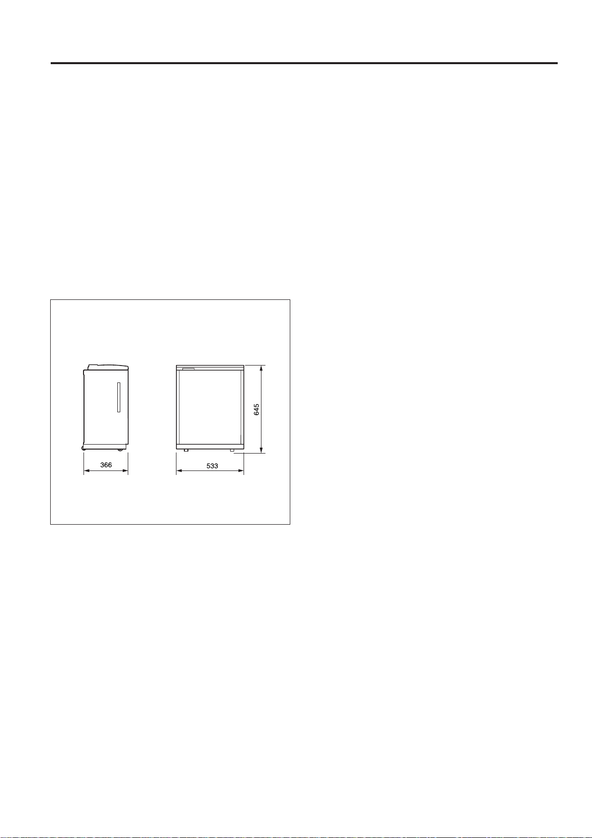
Weight: Approx. 26.6 kg
Machine dimensions
: 82 VA
: W 366 x D 553 x H 645
(Unit = mm)
4. Maintenance
Maintenance: Same as the main body
Machine life: Same as the main body
5. Operating Environment
Temperature: 10 to 33°C
Humidity: 10 to 80%RH
Note: The contents of this manual may be changed without
prior notice for the sake of improvement.
1 - 1
Page 5
LT-352
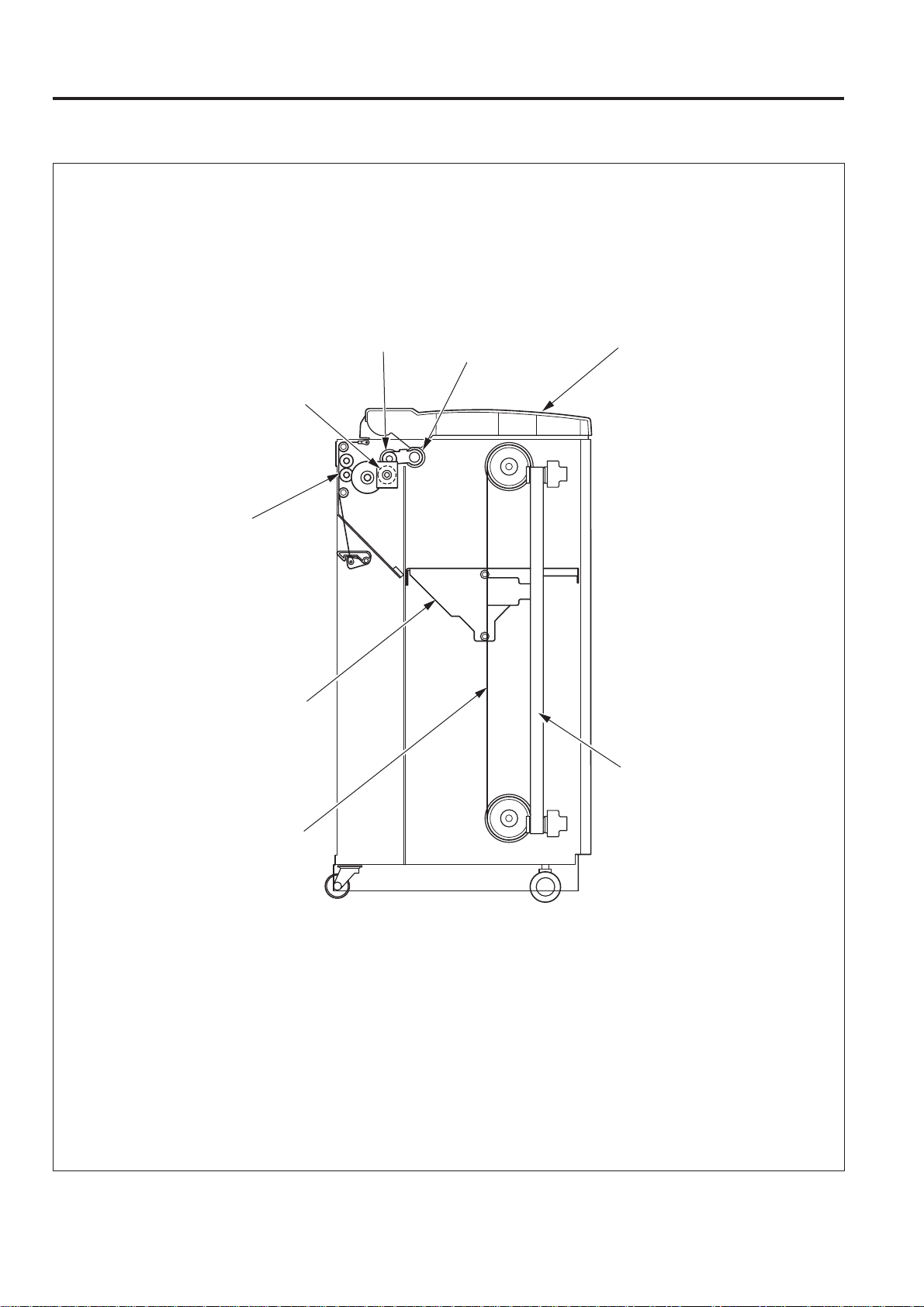
CENTER CROSS-SECTIONAL DRAWING
Double feed
prevention roller
Conveyance roller
Up/down plate
Feed roller
Paper feed roller
Upper cover
Remaining paper
indication belt
Up/down belt
1 - 2
Page 6

DRIVE SECTION
<Conveyance drive section>
Conveyance roller
LT-352
Paper feed motor
(M800)
Double feed prevention roller
Paper feed clutch
(MC800)
Feed roller
Paper feed roller
1 - 3
Page 7

LT-352
<Stacker drive section>
Up/down belt
Up/down plate
Remaining paper
indication belt
Up/down motor
Up/down shaft
1 - 4
Page 8

PAPER FEED SECTION
[1] Composition
Down button
LT-352
LT upper limit detection PS (PS801)
Paper feed roller unit
Up/down plate (Tray)
[2] Mechanisms
Mechanism Method
Paper lifting Belt drive
*1
Paper feed 1st paper feed roller
No paper detection PS800
Paper size detection None
Remaining paper indicator
*2
Paper conveyance Roller conveyance
Paper size A4, 8.5" x 11"
*1: Paper lifting
a. Lifting operation of the up/down plate
The up/down plate is lifted by belt drive.
When the upper cover is closed, the up/down plate
drive motor (M801) rotates, causing the up/down plate
coupled to the up/down drive belt to raise.
Linked to up/down plate
LT no paper detection PS (PS800)
b. Lowering operation of the up/down plate
When the upper cover is opened, the up/down plate
automatically falls 100 mm.
Subsequently, each time the down button is pressed,
the up/down plate falls a distance equal to the height of
the loaded paper.
*2: Remaining paper indicator
The amount of paper remaining in the paper tray can
be judged from the state of the indicator belt that is
visible from the front slit.
The indicator belt is directly linked to the up/down
motion of the up/down plate.
1 - 5
Page 9

LT-352
[3] Disassembly and Reassembly
1. Removing and Re-installing the Paper Feed roller
Unit
a. Procedure
(1) Open the upper cover.
(2) Remove the spring from the paper feed roller unit.
Upper cover
Spring
Paper feed
roller unit
2. Replacing the paper feed roller Rubber and the Feed
roller Rubber
a. Procedure
(1) Remove the paper feed roller unit.
(2) Remove the three stop rings and the three bearings on
the paper feed roller unit, and also the paper feed
reference actuator and the two shafts, then remove
each roller.
(3) Remove the rubber (feed rubber/A and double feed
prevention rubber) from each roller.
Paper feed
drive belt
Bearing
Feed rubber/A
Double feed
prevention
rubber
Paint mark
Feed roller
Blue mark
Stop ring
Bearing
Stop ring
(3) Remove the two stop rings and the two bearings, then
remove the paper feed roller unit.
Paper feed
roller unit
Bearing
Stop ring
Bearing
Stop ring
(4) Re-install the paper feed roller in the opposite se-
quence to removal.
Paper feed roller
Blue mark
Bearing
Stop ring
Paper feed
reference actuator
(4) Re-install the above parts in the opposite sequence to
removal.
Caution: Ensure that the mounting direction of the rubber and
rollers are correct.
1 - 6
Page 10

LT-352
3. Replacing the Double feed prevention roller rubber
a. Procedure
(1) Remove the three set screws, then remove the paper
feed cover (left).
Paper feed
cover (left)
Set screws
(2) Remove the two set screws, then remove the double
feed prevention roller unit. (When re-installing the unit,
align the drive coupling pin, then insert the two projections on the unit into the square holes before fixing the
two set screws.
(3) Remove the two stop rings, then pull out the shaft and
remove the double feed prevention roller together with
the paper feed reversal gear.
Paint mark
Double feed
prevention roller
(rubber)
Paper feed
Stop ring
Shaft
reversal gear
Stop ring
(4) Remove the double feed prevention rubber from the
double feed prevention roller.
(5) Re-install the above parts in the opposite sequence to
removal.
Caution: Ensure that the mounting direction of the rubber is
correct.
Double feed prevention
roller unit
Set screw
Set screw
1 - 7
Page 11

LT-352
4. Replacing the LT Clutch
a. Procedure
(1) Remove the four set screws, then remove the right
side cover.
Set screw
Set
screw
Right side cover
Set screw
Set screw
(2) Remove the four set screws, then remove the front
cover.
(3) Remove the two set screws, then remove the upper
cover.
Set screw
<Front>
Set screw
<Rear>
(4) Remove the four set screws, then remove the paper
feed cover (upper).
(5) Remove the three set screws, then remove the paper
feed cover (left).
Set screw
Set screw
Set screw
Front cover
Set screw
Paper feed cover
(upper)
Set screws
Set screws
Paper feed
cover (left)
1 - 8
Page 12

LT-352
(6) Disconnect the three relay connectors. (8) Remove the two set screws fixing the clutch cover from
the rear.
Relay connector (Large)
Relay
connector
(White)
Relay
connector
(Black)
(7) Remove the two E rings, then remove the two bear-
ings.
Set screw
Set screw
(9) Remove the hex socket screw, then remove LT clutch/2.
LT clutch/2 projection
Bearing
Bearing
Hex socket
screw
E rings
C ring
(10)Re-install the above parts in the opposite sequence to
removal.
Note: When re-installing the LT clutch, ensure that the projec-
tion is at the top.
1 - 9
Page 13

LT-352
[4] Centering adjustment of LT-352
Upper cover
Step
1
2
3
4
5
Set screws
Operation
Open the upper cover.
Slacken the side guide set screws (four each) at the
front and rear of the tray.
Move each side guide back and forth until the miscentering of the paper is within the standard value
range. (Move both guides by the same amount,
using the stamped marks on the guide reinforcing
plates (front/rear) and the LCT base plate below
them as a rough guide.)
Tighten the eight adjustment screws firmly, and
perform the centering adjustment for the 36 mode.
Repeat 1~4 until the miscentering value is within
the standard.
Set screws
1 - 10
Page 14

2
DIAGRAMS
Page 15

LT-352 ELECTRICAL PARTS LAYOUT DRAWING
LT-352
12
3
9
8
14
11
2
1
7
10
5
4
13
6
1. Switch/Sensor
1 PS800 LT no paper detection PS
2 PS801 LT upper limit detection PS
3 PS802 LT pre try PS
4 PS803 LT conveyance PS
5 PS804 LT release PS
6 PS805 LT lower limit detection PS
7 PS806 LT pre feed PS
8 SW800 LT down SW
9 SW801 LT cover open/close SW
2. Load
10 M800 LT paper feed Motor
11 M801 LT up/down Motor
12 MC800 LT 1st paper feed MC
3. Others
13 LT CB LT control board
14 HTR Heater
2 - 1
Page 16

LT-352
LT-352 CONNECTOR LAYOUT DRAWING
821(W:6 PIN)
811(B:3 PIN)
822(W:2 PIN)
823(BK:2 PIN)
812(R:3 PIN)
824(BK:2 PIN)
813(W:3 PIN)
826(BK:2 PIN)
816(BK:3 PIN)
816(W:3 PIN)
830(W:2 PIN)
810(W:3 PIN)
815(W:3 PIN)
820(W:11 PIN)
827(W:11 PIN)
814(W:3 PIN)
802(W:13 PIN)
803(W:18 PIN)
804(W:5 PIN)
800(W:5 PIN)
801(W:16 PIN)
391(W:2 PIN)
391(W:2 PIN)
127(BK:10 PIN)
126(BK:10 PIN)
2 - 2
831(W:2 PIN)
Page 17

LT-352 OVERALL WIRING DIAGRAM
LT DB
5V DC
SGND
M800 LD
M800 CONT
M800 MODE
M800 CLK
M800 FG
PGND
PGND
40V DC
40V DC
24V DC1
MC800 DRIVE
SGND
PS800
5V DC
PS801
PS802
SGND
PS803
5V DC
827-1803-A1
803-A2
803-A3
H
803-A4
H
803-A5
803-A6
P
803-A7
803-A8
803-A9
803-B8
803-B9
803-B1
803-B2
H
802-1
802-2
L
802-3
802-4
802-5
H
802-6
H
802-7
802-8
820-8 821-3 823-1
820-9
820-1
820-2
820-3
820-4
820-5
821-4 823-2
827-2
827-6
827-3
827-5
827-4
827-7
827-8
827-9
827-10
827-11
810-1
810-2
810-3
811-1
811-2
811-3
812-1
812-2
812-3
813-1
813-2
813-3
M800
MC800
PS800
PS801
PS802
PS803
LCT
PAPER
FEED
MOTOR
LCT 1st
PAPER FEED
CLUTCH
LCT
NO PAPER
SENSOR
LCT PAPER
UPPER LIMIT
SENSOR
LCT
PRE W
SENSOR
LCT
CONVEYANCE
SENSOR
40V DC
24V DC
PGND
5V DC
SGND
M800 CLK
M800 CONT
M801 CONT
PS806
MC800 CONT
M801 F/R
AC (H)
AC (N)
MAIN BODY
814-1
814-2
PS804
814-3
SW801
R
B
LCT
RELEASE
SENSOR
LCT COVER
DETECTOR
LCT TRAY
UP/DOWN
M801
MOTOR
816-1
816-2
816-3
PS805
SW800
LCT TRAY
LOWER LIMIT
SENSOR
LCT TRAY
DOWN
SWITCH
815-1
815-2
815-3
PS806
LCT
PRE-FEED
SENSOR
HRT
802-9
802-10
802-11
803-B3
803-B7
H
804-4
804-5
804-1
804-2
804-3
802-12
802-13
H
820-10 821-5 824-1
820-11 821-6 824-2
826-1
826-2
820-6 821-1 822-1
820-7 821-2 822-2
816-1
816-2
816-3
LCT
HEATER
126-1
88-4
126-2
99-1
126-3
88-2
126-4
140-A1
126-5
140-A2
126-6
140-A3
P
H
L
H
H
140-A4
140-A5
140-A6
140-A8
140-A9
140-B1
140-B2
140-B3
140-B4
140-B5
140-B6
140-B7
140-B8
140-B9
752-1
752-2
126-7
126-8
126-9
126-10
127-1
127-2
127-3
127-4
127-5
127-6
127-7
127-8
127-9
127-10
127-11
391-1
391-2
BK
W
391-1
391-2
800-1
800-2
800-3
800-4
800-5
801-A1
801-A2
801-A3
801-A4
801-A5 NC140-B10
801-A6
801-A7
801-A8
801-B1
801-B2
801-B3
801-B4
801-B5
801-B6
801-B7
801-B8
BK
W
M800 PLL
H
PS800
L
PS801
L
L
PS802
H
PS803
L
LT352 ADD (NC)
SW801
L
PS804
L
H
SW800
PS805
H
830-1
830-2
831-1
831-2
SGND
PS804
5V DC
24V DC
SW801
M801 DRIVE 1
M801 DRIVE 2
SGND
PS805
5V DC
SGND
SW800
2 - 3
 Loading...