

Page 1

PI-108
SERVICE HANDBOOK
Sep.1999
Ver.1.0
KONICA CORPORATION
TECHNOLOGY SUPPORT CENTER
TOKYO JAPAN
Page 2

CONTENTS
CONTENTS
SAFETY AND IMPORTANT WARNING ITEMS
Refer to the 7065 service handbook on page C-1
1. PI-108
PI-108 PRODUCT SPECIFICATIONS ..............1-1
CENTER CROSS SECTION.............................1-2
EXTERNAL SECTION.......................................1-3
[1] Composition.........................................1-3
[2] Disassembly and Reassembly.............1-3
DRIVE SYSTEM DIAGRAM..............................1-4
PAPER FEED UNIT...........................................1-5
[1] Composition.........................................1-5
[2] Mechanisms.........................................1-5
[3] Disassembly and Reassembly.............1-7
[4] Feed Control ........................................1-9
PI-108 ADJUSTMENTS ..................................1-12
[1] Adjusting the Size of the Coversheet-Tray
Width Regulation Plates ....................1-12
..............
2. DIAGRAM
PI-108 ELECTRICAL PARTS LAY OUT DRA WING ... 2-1
PI-108 CONNECTOR LAYOUT DRAWING ......2-3
PI-108 OVERALL WIRING DIAGRAM ..............2-5
PI-108 DRIVE BOARD CIRCUIT DIAGRAM.....2-6
PI-108
OPERATION BO ARD CIRCUIT DIA GRAM .....
PI-108 TIMING CHAR T (AUTO-FEED[ONLINE],
2 STAPLE,A4,2-PAGE ORIGINAL,2 COPIES) . ..2 -8
2-7
This section covers the structure,functions,operation and method of disassembling and assembling the machine.
Observe the following precautions when performing disassembly and assembly work.
1. Be sure to unplug the power cord before working on the machine.
2. Perform all reassembly work by reversing the order in which the component was disassembled,unless otherwise specified.
3. Do not lose small parts (screws,etc.) or insert them in the wrong place.
4. Install all parts completely before operating the machine.
5. Do not loosen the screws indicated as disallowed for removal.
Page 3

1
PI-108
Page 4

PI-108 PRODUCT SPECIFICATIONS
PI-108
1. Type
Sheet feeder employing torque-limiter separation
2. Functions
Automatic sheet feed (online operation)
The PI-108 automatically feeds sheets into the finisher
in accordance with instructions from the copier.
Manual sheet feed (offline operation)
User feeds sheets into finisher by operating the PI-108
controls.
User can select from three finishing modes.
• Booklet mode (available only if mounted to the FS108BM)
• Single-staple mode (staple at rear)
• Two-staple mode (flat stapling)
Copy paper
Plain paper
(high-quality paper, recycled paper, etc.)
(60g/m
Special paper
• OHP film
• Label paper
• Blueprint master paper
• 50 to 59g/m
• 91 to 200g/m
Printing paper
• Double-sided art paper
• Mat paper
• High-quality paper
2
to 90g/m2)
2
high-quality paper
2
high-quality paper
3. Power , Weight, Dimensions
Power Source: 24VDC, 5VDC (supplied from finisher)
Maximum power: Max. 25VA
Weight: PI-108: Approx. 7kg
External dimensions:
PI-108: Appro x. 330(W) x 120(H) x 456(D) (mm)
4. Maintenance
Maintenance: Same as for the main body.
Service life: Same as the main body.
5. Machine Operating Environment
Temperature: 10 to 30˚C
Humidity: 10 to 80% RH
These specifications are subject to change without notice.
Copy sizes: A3R, B4R, A4R, A4, B5, A5
Paper staking capacity: Up to 200 sheets (when using
130g/m
max. height of 40mm
Paper curling: Max. 10mm
Amount of curl
2
-equivalent paper), to
5 sheets of copy paper
1-1
Page 5

PI-108
CENTER CROSS SECTION
Paper Feed Roller
Width Regulation Plates
Feed Roller
M201 (Sheet Tray)
Sheet T ra y
Double-Feed prevention Roller
1-2
Page 6
EXTERNAL SECTION
[1] Composition
Cover A
Plate
PI-108
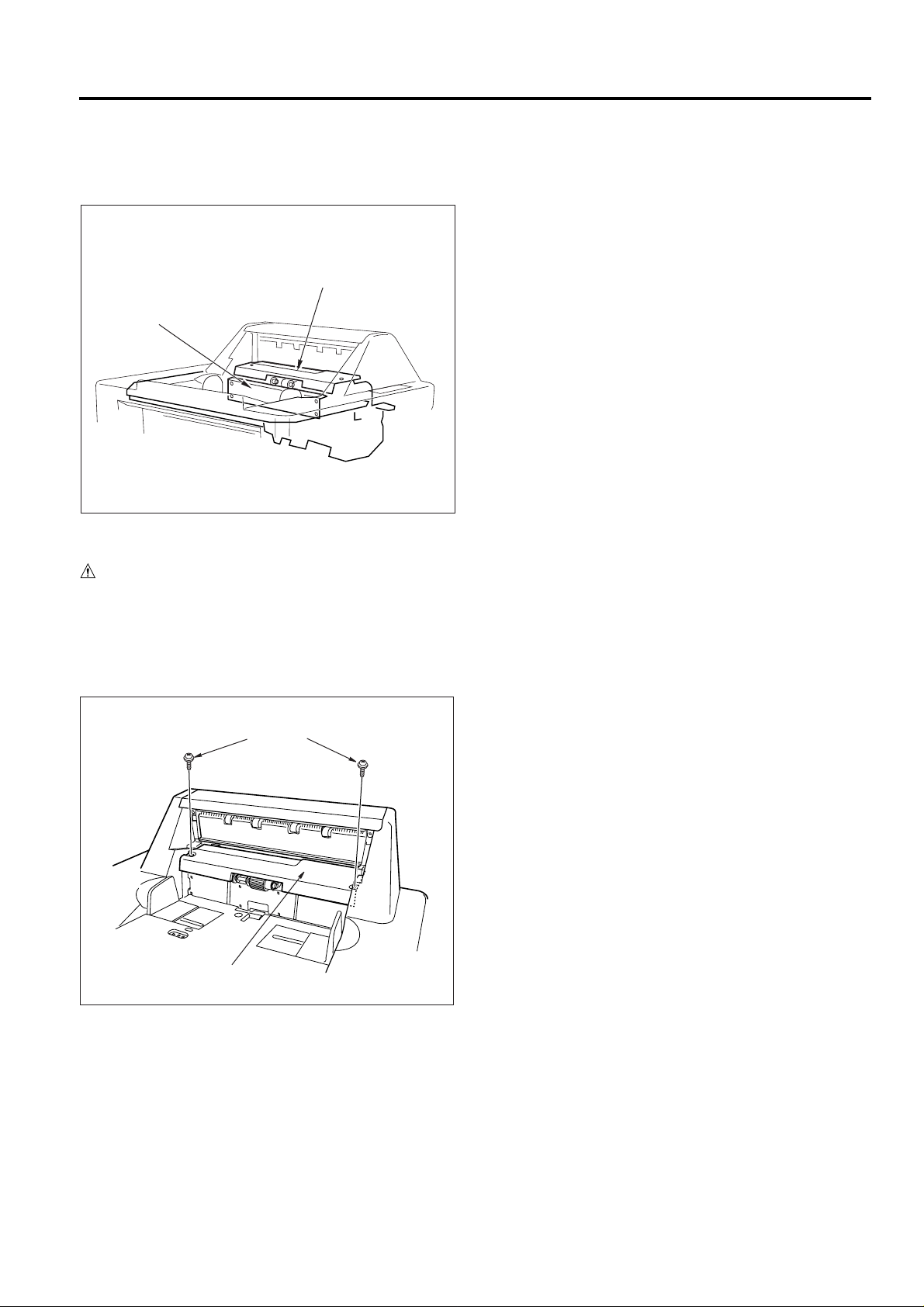
[2] Disassembly and Reassembly
CAUTION: Be sure that the power cord has been un-
plugged from the outlet.
1. Removing and Installing the Cover A
a. Procedure
(1) Remove the sub-tray.
(2) Remove the 2 screws and remove the cover A.
Screws
Cover A
1-3
Page 7
PI-108
DRIVE SYSTEM DIAGRAM
M201 (Sheet Tray)
1-4
Page 8

PAPER FEED UNIT
[1] Composition
PI-108
M1 (FNS Conveyance motor)
Double-Feed prevention Roller
MC201 (Paper Feed Clutch)
Feed Roller
Paper Feed Roller
SD201 (Paper-Feed solenoid)
[2] Mechanisms
Mechanism
Paper Feed
Double-Feed Prevention
Sheet Width Detection
Method
Automatic Conveyance
(Top feeding)
Double-Feed prevention Roller
VRI
1-5
Page 9

PI-108
Paper Feed Roller
Feed Roller
M201 (Sheet Tray Motor)
Sheet T ra y
Double-Feed
prevention Roller
1. Automatic Sheet Feeding (online operation)
M201 (sheet tray motor) raises the sheet tray. SD201 (paper feed solenoid) and MC201 (paper-feed clutch) goes
on, causing the paper-feed, feed, and double-feed-prevention rollers to turn. This action feeds sheets, one by one,
into the stacker section. The rollers are driv en by FNS motor
M1 (FNS conveyance motor) via a timing belt.
Sheets are stacked as cover sheets onto paper from the
copier, and the results are then processed by the FNS
(single staple, double staple, or booklet generation).
Paper Feed Roller
Sheet T ra y
Double-Feed
prevention Roller
Feed Roller
M201 (Sheet Tray Motor)
2. Manual Sheet Feeding (offline operation)
M201 (sheet tray Motor) raises the sheet tray. SD201 (paper feed) and MC201 (paper-feed clutch) goes on, causing the paper-feed, feed, and double-feed-prevention rollers to turn. This action feeds all of the sheets from the
sheet tray into the stacker section. The FNS carries out
the required finishing (single stapling, double stapling, or
booklet generation).
1-6
Page 10

PI-108
Screws
Screws
Plate
[3] Disassembly and Reassembly
1. Replacing a Paper-Feed Roller and Feed Roller
a. Procedure
(1) Remove the sub-tray and the cover A.
(2) Remove the 2 Stop rings, Then shift the left and
right bearings outside, and remove the feedroller unit.
Stop ring
Stop ring
Bearing
Bearing
Feed Roller
Paper Feed Roller
(4) Re-install the paper-feed roller and feed roller in
the opposite sequence to removal.
CAUTION: Ensure that the mounting direction of the rubber
is correct.
2. Replacing the Rubber,Double-Feed-Prevention
Roller
a. Procedure
(1) Remove the cover A.
(2) Remove the feed-roller unit. Refer to the previ-
ous procedure for instructions on removing the
unit.
(3) Remove the 4 set screws, Then remove the plate.
(3) Pull out three stop rings,the three bearings,the
actactuator and two shaft of the feed-roller unit
then remove each roller .
Paint Mark
Rubber
Feed Drive Belt
Bearing
Rubber
Feed Roller
Feed Roller
Blue Mark
Blue Mark
Stop Ring
Bearing
Bearing
Stop Ring
Stop Ring
Actuator
1-7
Page 11

PI-108
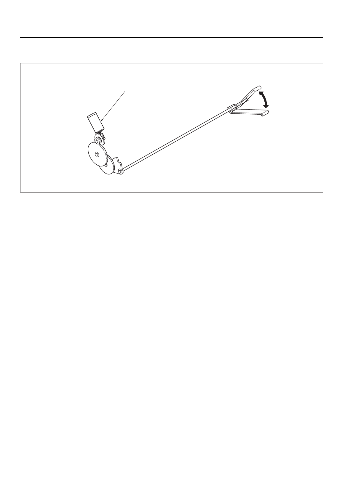
(4) Remove the 3 stop rings, then pull out the shaft,
and remove the double-feed-prevention roller together with the feed-reverse gear.
Stop rings
Paint mark
Feed
Reverse Gear
Shaft
Double-Feed Prevention Roller
(5) Remove the rubber from the double-feed-pre-
vention roller.
(6) Re-install the removed parts in the reverse se-
quence to removal.
CAUTION: Ensure that the mounting direction of the rubber
is correct.
1-8
Page 12

[4] Feed Control
PI-108
M1
PS207
24V
SGND
PGND
PGND
TXD
DTR
CTS
RXD
DSR
RTS
MAIN BODY
MC201
SD201
M201
2-2
2-1
2-6
2-5
2-4
PS201
PS202
PS203
PS204
PS205
PS206
2-3
24V3
MC201CONT
24V2
DB
M201F/R
M201CONT
SD201CONT
8-1
5V
8-2
M1 BRK
8-3
M1 CONT
8-4
M1 CLK
8-5
M1 PLL
8-6
M1 F/R
8-7
24V
8-8
24V
8-9
PGND
8-10
PGND
1-A13
1-B18
1-A22
MS1
28-6
2-9
5V
2-7
28-3
28-1
114-1
NC
114-2
NC
114-5
NC
114-3
NC
114-7
NC
114-6
NC
6-3
6-4
6-5
6-6
7-1
7-2
7-3
7-4
7-5
7-6
7-7
7-8
7-9
7-10
7-11
7-12
5V
PS207IN
GND
24V-IN
6-1
5V
SGND
PGND
PGND
RX
SGND
CTS
SGND
DTR
SGND
TXD
SGND
RTS
SGND
DSR
SGND
M201CONT
M201F/R
MC201CONT
SD201CONT
SEETSET
PS201 IN
PS202 IN
PS203 IN
PS204 IN
PS205 IN
PS206 IN
24V
SGND
PGND
GND
GND
GND
GND
GND
GND
51-B2
51-B14
5V
51-A20
51-A21
51-A22
51-A23
51-A24
51-B1
51-B3
51-B25
5V
51-A1
51-B13
51-B24
5V
51-A2
51-B12
51-B23
5V
51-A3
51-B11
51-B22
5V
51-A4
51-B10
51-B21
5V
51-A5
51-B9
51-B20
5V
51-A6
51-B8
1-1
1-2
1-3
1-4
1-5
1-6
1-7
1-8
1-9
24V
5V
M201CONT
M201F/R
MC201CONT
SD201CONT
SEETSET
SGND
PGND
VR1
OB
1-7
1-8
51-A17
51-A18
51-B16
51-A10
51-B4
SW1
SW2
5V
VR1 IN
GND
FNS CB
M201 (sheet tray) raises the sheet tra y . SD201 (paper feed)
and MC201 (paper-feed clutch) operate in accordance with
the feed mode, thereby causing the feed, transmit, and
double-feed-prevention rollers to turn, feeding sheets into
the stacker section. The rollers are driven by FNS motor
M1 (FNS conveyance). M201 and MC201 are controlled
by the FNS CB (FNS control board) via the DB (drive
board).
PS208 IN
GND
PS209 IN
GND
5V
51-B18
51-A8
51-B6
5V
51-B17
51-A9
51-B5
PS208
PS209
1-9
Page 13

PI-108
Sheet T ra y
Operation Panel
SD201 (Paper Feed)
PS204 (Sheet Tray Upper Limit)
M201 (Sheet Tray)
MC201
(Paper-Feed Clutch)
1. Operation
a. Auto-sheet feeding (online)
(1) The ON signal from the copier’s START button
causes FNS motor M1 (FMS conveyance) to
come on. M201 (sheet tray) lifts the sheet tray
up to the position where the tray activates PS204
(sheet-tray upper limit).
(2) SD201 (paper-feed) and MC201 (paper-feed
clutch) come on in response to the CF feed request signal, feeding paper into the stacker.
M201 (Sheet Tray)
MC201
(Paper-Feed Clutch)
PS204 (Sheet-Tray Upper Limit)
SD201 (Paper Feed)
b. Manual sheet feeding (offline)
(1) The ON signal from the PI-108 operation panel’s
ST AR T button causes FNS motor M1 (FMS conveyance) to come on. M201 (sheet tray) lifts the
sheet tray to the position where the tray activates PS204 (sheet-tray upper limit).
(2) SD201 (paper-feed) and MC201 (paper-feed
clutch) come ON, feeding all paper from the
sheet tray into the stacker.
(3) The FNS carries out the required processing
(stapling or booklet generation).
Sheet T ra y
1-10
Page 14

PI-108
c. Detection of sheet size
VR1 (sheet width) detects the sheet width. Sheet length is
detected by the combination of PS205 (sheet size/small)
and PS206 (sheet size/large).
PS205 (Sheet-Size (Small))
PS206
(Sheet-Size (Large))
Width Regulation Plates
VR1 (Sheet Width)
d. Sheet tray up-down
M201 (sheet tray) drives the raising and lowering of the
tray . M201 is controlled b y the FNS CB (FNS control board)
via the DB (drive board).
2. Signals
a. Input signals
(1) TXD (Main-Body CB → FNS CB)
Serial data line; transmits operating status of the
Main-Body CB to the FNS CB.
(2) DTR (Main-Body CB → FNS CB)
Request to send signal from the main body to
the FNS.
(3) RTS (Main-Body CB → FNS CB)
Transmission acknowledgment signal from the
main body to the FNS.
(4) PS201 IN (PS201 → RB → FNS CB)
Comes ON [L] when paper passage is detected.
(5) PS202 IN (PS202 → RB → FNS CB)
Sheet-tray empty detection.
[H]: Tray is empty (no paper).
[L]: Tray has paper.
(6) PS203 IN (PS203 → RB → FNS CB)
Comes ON [L] when the sheet tray is at its lowerlimit position.
(7) PS204 IN (PS204 → RB → FNS CB)
Comes ON [L] when the sheet tray is at its upper-limit position.
(8) PS205 IN (PS205 → RB → FNS CB)
Paper-size detection.
[H]: Paper not detected
[L]: Paper detected
(9) PS206 IN (PS206 → RB → FNS CB)
Paper-size detection.
[H]: Paper not detected
[L]: Paper detected
(10)PS208 IN (PS208 → RB → FNS CB)
Paper-size detection.
[H]: Paper not detected
[L]: Paper detected
(11) PS209 IN (PS209 → RB → FNS CB)
Paper-size detection.
[H]: Paper not detected
[L]: Paper detected
(12)VRI IN (VR1 → RB → FNS CB)
Width detection (paper size in tray width direction).
b. Output signals
(1) TXD (FNS CB → Main-Body CB)
Serial data line; transmits FNS operating status
to the Main-Body CB.
(2) DTR (FNS CB → Main-Body CB)
Request to send signal from the FNS to the main
body .
(3) RTS (FNS CB → Main-Body CB)
Transmission acknowledgment signal from the
FNS to the main body.
(4) M201 CONT (FNS CB → RB → M201)
M201 (sheet-tray) drive control signal.
(5) MC201 CONT (FNS CB → RB → MC201)
MC201 (paper-feed clutch) drive control signal.
(6) SD201 CONT (FNS CB → RB → SD201)
SD201 (paper-feed solenoid) drive control signal
[H]: OFF
[L]: ON
1-11
Page 15

PI-108
PI-108 ADJUSTMENTS
[1] Adjusting the Size of the Coversheet-
Tray Width Regulation Plates
1. Preparation
(1) Install the coversheet tray (PI-108) on the fin-
isher.
(2) Connect the finisher to the copier.
(3) Check whether all paper sizes are correctly de-
tected.
(4) If one or more sizes are not correctly detected,
carry out adjustment as described below.
2. Adjustment procedure
(1) Hold down keys [3] and [6] on the copier’s nu-
meric keypad while setting the main switch ON.
The copier will enter finisher-adjustment mode.
(2) Select [[6] Finisher Adjust] at the copier display.
(3) Again at the copier display, select [[4] Adjust
coversheet tray size].
(4) Push the width regulation plates out to maximum
width.
Width
Regulation Plates
(5) At the screen, select [YES].
(6) Confirm that the following message is displayed,
indicating that adjustment is finished.
Adjust coversheet tray size
----Adjustment completed.----
1-12
Page 16

2
DIAGRAM
Page 17

PI-108 ELECTRICAL PARTS LAYOUT DRAWING
PI-108
1. Sensors
PS201 Sheet passage PS
PS202 No-sheet PS
PS203 Sheet-tray lower-limit PS
PS204 Sheet-tray upper-limit PS
PS205 Sheet-size PS (small)
PS206 Sheet-size PS (large)
PS208 Sheet set PS
PS209 Pre no-paper PS
VR1 Sheet-width VR
2-1
Page 18

PI-108
2. Motor, Clutch, Solenoid, Board
M201 Sheet-tray motor
MC201 Paper-feed clutch
SD201 Paper-feed solenoid
DB Drive board
OB Operation board
2-2
Page 19

PI-108 CONNECTOR LAYOUT DRAWING
503(W:6 PIN)
356(W:3 PIN)
356(W:3 PIN)
PI-108
54(W:9 PIN)
2(W:6 PIN)
DB
1(W:9 PIN)
355(W:3 PIN)
353(W:3 PIN)
359(W:3 PIN)
302(W:2 PIN)
501(W:9 PIN)
352(W:3 PIN)
351(W:3 PIN)
354(W:3 PIN)
303 (W:3 PIN)
358(W:3 PIN)
360(W:3 PIN)
2-3
Page 20

[Reading the Diagrams]
1. Signal states reflect condition in which system is in normal idling state with the main switch ON.
2. Symbols used in circuit diagrams are as follows.
(1) Symbols (3) RC denotes a ribbon cable.
(4) Signal Flow
Connectors are indicated by circle ( ) or ( ).
The dark circles indicate the direction of the signal flow.
(2) Color Codes
Example: Y/GN denotes a green wire with a yellow stripe.
BN : Brown
R : Red
O : Orange
Y : Yellow
GN : Green
LB : Light blue
B : Blue
V : Violet
GY : Gray
W : White
BK : Black
P : Pink
PGC Wire (Violet)
Connector Faston
VV
CB
Example:
Direction of signal flow:
PS1
5VDC
PS1
SGND
50-1
351-3
351-2
351-1
PS201
H
51-B25
51-A1
51-B13
M201
MC201
352-3
352-2
352-1
PS202
H
51-B24
51-A2
51-B12
353-3
353-2
353-1
PS203
L
51-B23
51-A3
51-B11
354-3
354-2
354-1
PS204
H
51-B22
51-A4
51-B10
355-3
355-2
355-1
PS205
L
51-B21
51-A5
51-B9
503-3
503-2
503-1
356-3
356-2
356-1
PS206
L
51-B20
51-A6
51-B8
5V
PS201 IN
GND
5V
PS202 IN
GND
5V
PS203 IN
GND
5V
PS204 IN
GND
358-3
358-2
358-1
PS208
L
51-B18
51-A8
51-B6
359-3
359-2
359-1
PS209
L
51-B17
51-A9
51-B5
360-3
360-2
360-1
VR1
OB
51-B16
51-A10
51-B4
5V
PS208 IN
GND
5V
PS209 IN
GND
5V
VR1 IN
GND
FNS CB
DB
5V
PS205 IN
GND
5V
PS206 IN
GND
51-B19
51-A7
51-B7
NCNCNC
51-A25
51-B15
NC
NC
503-6
503-5
503-4
1-1
1-2
1-3
1-4
1-5
1-6
1-7
1-8
1-9
24V5VM201CONT
M201F/R
MC201CONT
SD201CONT
SHEETSET
SGND
PGND
51-B2
51-B14
51-A20
51-A21
51-A22
51-A23
51-A24
51-B1
51-B3
2-2
2-1
2-6
2-5
2-4
2-3
53-2
53-1
53-6
53-5
53-4
53-3
M201F/R
M201CONT
SD201CONT
24V3
MC201CONT
24V2
24V
5V
M201CONT
M201F/R
MC201CONT
SD201CONT
SHEETSET
SGND
PGND
52-1
52-2
52-3
52-4
52-5
52-6
52-7
52-8
52-9
H
H
51-A11
51-A12
51-A13
51-A14
51-A15
51-A16
51-A17
51-A18
51-A19
5V
LED1
LED2
LED3
LED4
LED5
SW1
SW2
SGND
54-1
54-2
54-3
54-4
54-5
54-6
54-7
54-8
54-9
1-1
1-2
1-3
1-4
1-5
1-6
1-7
1-8
1-9
501-1
501-2
501-3
501-4
501-5
501-6
501-7
501-8
501-9
301-1
301-2
SD201
303-1
303-2
302-1
302-2
PAPER
FEED
CLUTCH
PAPER
FEED
SOLENOID
SHEET
TRAY
MOTOR
SHEET
PASSAGE
PS
NO SHEET
PS
SHEET
TRAY
LOWER LIMIT
PS
SHEET
TRAY
UPPER LIMIT
PS
SHEET
SIZE
PS
(SMALL)
SHEET
SIZE
PS
(LARGE)
SHEET
SET
PS
PRE
NO PAPER
PS
SHEET
SIZE
VR
PI-108 OVERALL WIRING DIAGRAM
2-5
Page 21

PI-108 DRIVE BOARD CIRCUIT DIAGRAM
By-pass condensers for IC1,IC2 IC3
2-6
Page 22

PI-108 OPERATION BOARD CIRCUIT DIAGRAM
2-7
Page 23

PI-108 TIMING CHAR T(AUTO-FEED [ONLINE],2-STAPLE,A4,2-PAGE ORIGINAL,2 COPIES)
Symbol
Item
Copier Exit PS
FIN Entrance Passage PSPS4
FNS Conveyance MotorM1
Paper Exit-Roller MotorM7
Paper Exit Opening SolenoidSD4
Paper Exit-1 PSPS6
Staple Paper Exit Upper-Limit PSPS7
Tray Up-Down MotorM3
CF Feed Request
CF Pre-Feed Request
Staple Request
Sheet Passage PSPS201
Stacker Conveyance Passage PSPS5
Paper Feed ClutchMC201
Paper-Feed SolenoidSD201
Alignment-Plate/Upper Motor M5
Stapler/RM21,M22
Stapler/FM23,M24
Stacker Entrance MotorM13
Time (seconds)
UP
DOWN
0 1 2 3 4 5 6 7 8 9 10 11 12 13 14 15 16 17 18 19 21 2220
2-8
 Loading...