

Page 1

FS-106
SERVICE HANDBOOK
Jan. 2000
Ver. 2.0
KONICA CORPORATION
TECHNOLOGY SUPPORT CENTER
TOKYO JAPAN
Page 2

CONTENTS
CONTENTS
SAFETY AND IMPORTANT WARNING ITEMS ................
Refer to the 7065 service handbook on page C-1
1. FS-106
FS-106 PRODUCT SPECIFICATIONS ............ 1-1
CENTER CROSS SECTION ............................ 1-2
DRIVE SYSTEM DIAGRAM............................. 1-3
[1] Paper Conveyance Drive ..................... 1-3
[2] Stacker Drive ....................................... 1-4
PAPER CONVEYANCE PATH......................... 1-5
[1] Paper Conveyance Path ...................... 1-5
[2] Non-Sort mode..................................... 1-6
[3] Sort/Group mode ................................. 1-7
[4] Sub-tray mode ..................................... 1-8
[5] Staple mode......................................... 1-9
EXTERNAL SECTION.................................... 1-10
[1] Composition ....................................... 1-10
[2] Disassembly and Assembly ............... 1-10
CONVEYANCE SECTION.............................. 1-13
[1] Composition ....................................... 1-13
[2] Mechanism......................................... 1-13
[3] Disassembly and Assembly ............... 1-16
[4] M1 (1st conveyance) Control ............. 1-23
[5] M4 (2nd conveyance) Control ............ 1-24
[6] Gate Control....................................... 1-26
[7] M14 (Stacker Entrance) Control ........ 1-28
[8] M5 (Alignment Plate) Control ............. 1-29
[9] M2 (Roller Shift) Control .................... 1-30
[10] M7 (Paper Exit Roller) Control ........... 1-31
[11] SD4 (Paper Exit Opening) Control..... 1-32
[12] M8 (Paper Exit Opening) Control....... 1-34
STAPLER UNIT .............................................. 1-35
[1] Composition ....................................... 1-35
[2] Mechanism......................................... 1-35
[3] Disassembly and Assembly ............... 1-36
[4] Stapler Control ................................... 1-38
MAIN TRAY SECTION ................................... 1-40
[1] Composition ....................................... 1-40
[2] Mechanism......................................... 1-40
[3] Disassembly and Assembly ............... 1-40
[4] Main Tray Up-Down Control ............... 1-42
FS-106 ADJUSTMENTS ................................ 1-44
[1] Sub-tray Gate Adjustment.................. 1-44
[2]
Adjusting the Paper Route Switching Gate ..
[3] Adjusting the By-Pass Gate ............... 1-46
[4] Adjusting the Shift Position ................ 1-47
[5] Adjusting the Open/Close Section of
the Paper Exit Opening...................... 1-48
[6]
Adjusting the Paper Exit Opening Solenoid..
[7] Adjusting the Paper Exit Opening
Lower Guide Plate ............................. 1-50
[8]
Adjusting the Stacker Paper Exit Belt Tension ..
[9] Adjusting the Alignment Plate Installation
Position .............................................. 1-51
[10] Adjusting the Alignment Plate Drive
Timing Belt Tension............................ 1-52
[11] Adjusting the Stapler Rotation Drive
Section Installation............................. 1-52
[12] Adjusting the Staple Position for
2 Position Stapling ............................. 1-53
[13] Adjusting the Staple Slant for
2 Position Stapling ............................. 1-53
[14] Adjusting the Staple Position for
1 Position Stapling ............................. 1-54
[15] Adjusting the Tension of the Stapler
Move Timing Belt ............................... 1-54
2. DIAGRAMS
FS-106 ELECTRICAL PARTS LAYOUT DRAWING...
FS-106 CONNECTOR LAYOUT DIAGRAM..... 2-3
FS-106 OVERALL WIRING DIAGRAM ............ 2-5
FS-106 CONTROL BOARD CIRCUIT DIAGRAM (1/7) .....
FS-106 CONTROL BOARD CIRCUIT DIAGRAM (2/7) .....
FS-106 CONTROL BOARD CIRCUIT DIAGRAM (3/7) .....
FS-106 CONTROL BOARD CIRCUIT DIAGRAM (4/7) .....
FS-106 CONTROL BOARD CIRCUIT DIAGRAM (5/7) ..
FS-106 CONTROL BOARD CIRCUIT DIAGRAM (6/7) ...
FS-106 CONTROL BOARD CIRCUIT DIAGRAM (7/7) ..
FS-106 TIMING CHART (Sort mode, A4, 2 page
originals, 5 copies, 1:1 ratio) ..............................
FS-106 TIMING CHART (2 position staple mode,
A4, 2 page originals, 3 copies)...........................
1-45
1-49
1-51
2-1
2-6
2-7
2-8
2-9
2-10
2-11
2-12
2-13
2-14
This section covers the structure, functions, operation and method of
disassembling and assembling the machine.
Observe the following precautions when performing disassembly and
assembly work.
1. Be sure to unplug the power cord before working on the machine.
2. Perform all reassembly work by reversing the order in which the
component was disassembled, unless otherwise specified.
3. Do not lose small parts (screws, etc.) or insert them in the wrong
place.
4. Install all parts completely before operating the machine.
5. Do not loosen the screws indicated as disallowed for removal.
Page 3

1
FS-106
Page 4
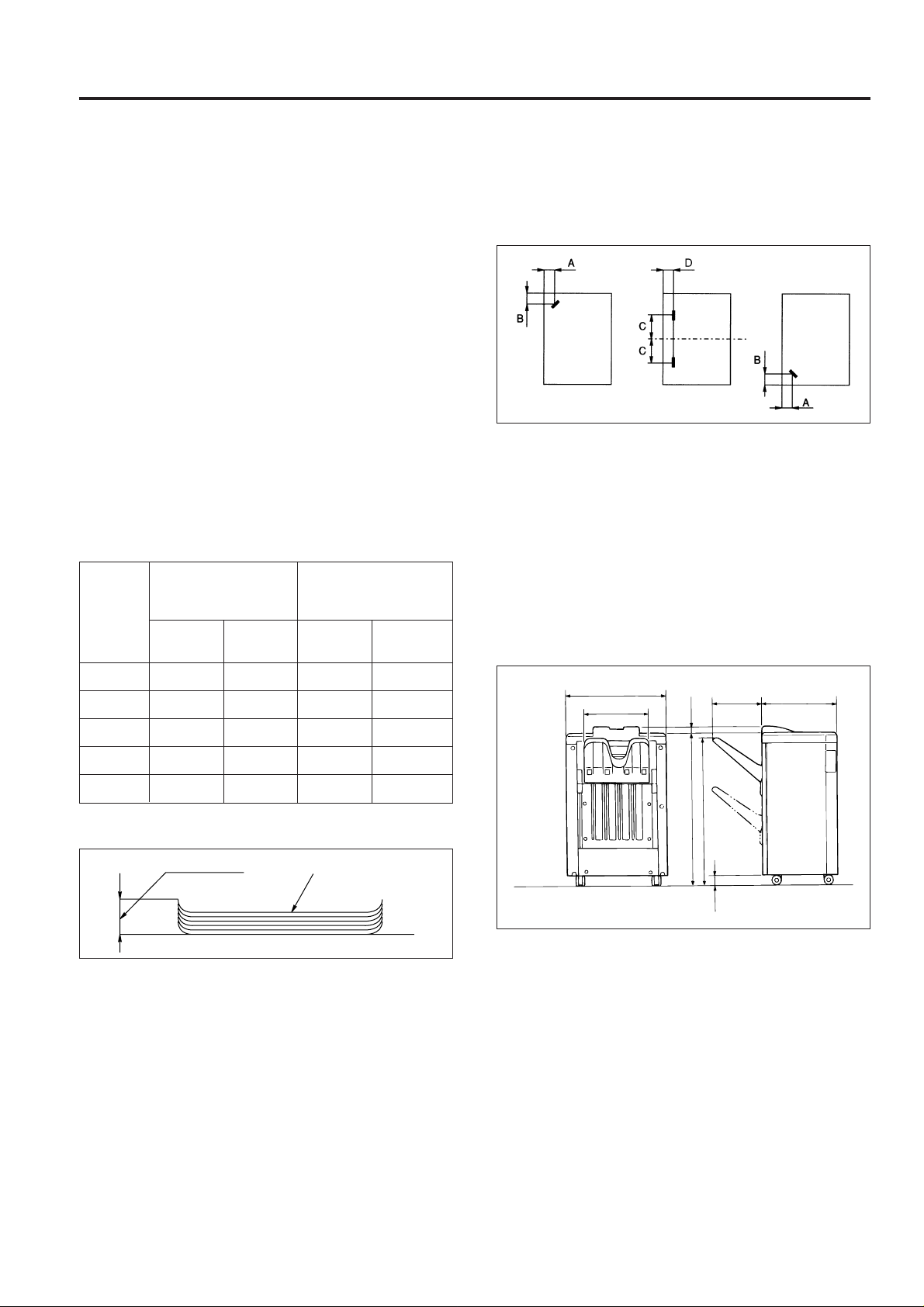
FS-106 PRODUCT SPECIFICATIONS
616
367
324 460
915
945
35
63
FS-106
1. Type
Type: Off-set sorting and stapling equipment
with printer outlet function.
2. Functions
Types of paper: Same as the main body.
Paper size: A3R, B4R, F4R, A4R, A4, B5, B5R,
A5R, B6R; however
B6R is not possible in off-set mode;
B5R, A5R and B6R are not possible in
staple mode.
Paper stacking capacity:
Sub-tray exit mode: Maximum 200 sheets
Non-staple/Group/
Off-set mode: Maximum 1,500 sheets (B4R/F4R/
A3R)
Maximum 2,000 sheets (B5R/B5/
A4R/A4)
Maximum 500 sheets (B6R/A5R)
Staple mode: Maximum 1,000 sheets
Other than
Number of
original
pages Staple in Staple in Staple in Staple in
2 to 9 100 stacks 100 stacks 50 stacks 50 stacks
A3R, 11X17R
2 places 1 place 2 places 1 place
A3R, 11x17R
Staple position: A = 8.8 mm (±3 mm adjustment possible)
B = 8.8 mm (±3 mm adjustment possible)
C = 89.1 mm (±3 mm adjustment possible)
D = 8.0 mm (±3 mm adjustment possible)
Staple capacity: 5,000 staples/cartridge
(Same as FS-103/FS-103A/FS-106)
4. Machine Data
Power source: 24 V/5 VDC (supplied from the main
body).
Maximum power
consumption: Max. 100 VA (FS-106 only)
Weight: Approximately 50 kg
External dimensions:
Units: mm
10 to 20 50 stacks 50 stacks 50 stacks 50 stacks
21 to 30 30 stacks 30 stacks 30 stacks 30 stacks
31 to 40 25 stacks 25 stacks 25 stacks 25 stacks
41 to 50 20 stacks 20 stacks 20 stac ks 20 stacks
Paper curling: Max. 10 mm
5 sheets of copy paperAmount of curl
Amount of sort
off-setting: 30 mm (when off-setting/grouping)
Tray: Main tray
Sub-tray
3. Stapler Kit
Number of pages
which may be
stapled: 50 sheets maximum (80 g/m
paper, 5 mm and below)
2
high-quality
5. Maintenance
Maintenance: Same as the main body
Service life: Same as the main body
6. Machine Operating Environment
Temperature: 10 to 30°C
Humidity: 10 to 80% RH
These specifications are subject to change without notice.
1 - 1
Page 5
FS-106
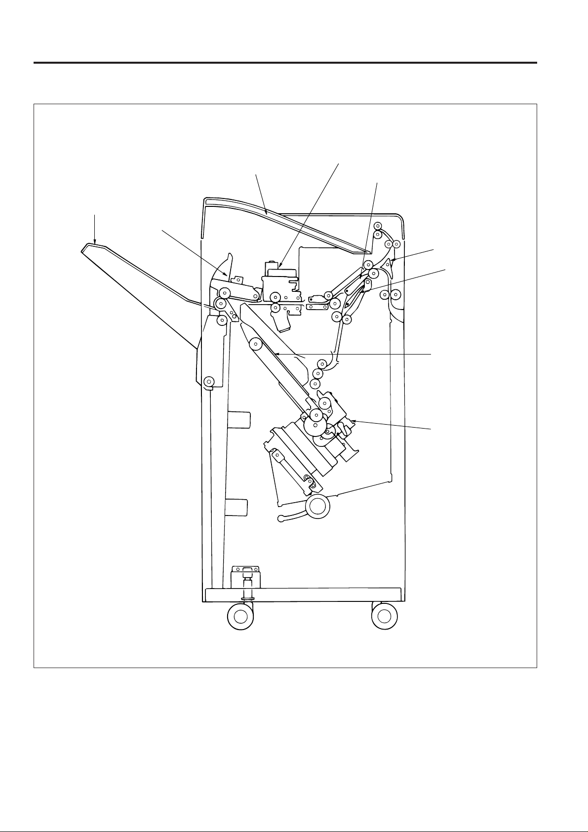
CENTER CROSS SECTION
Sub-tray
Main tray
Paper exit unit
Shift unit
Gate
Sub-tray gate
By-pass gate
Stacker unit
Stapler unit
1 - 2
Page 6
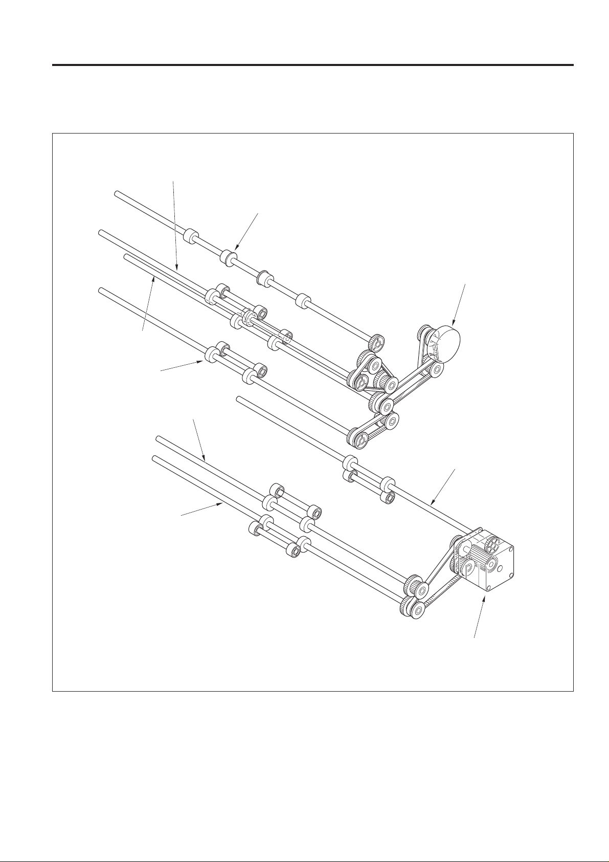
DRIVE SYSTEM DIAGRAM
[1] Paper Conveyance Drive
Conveyance roller D
Sub-tray printer paper exit roller
Conveyance roller B
FS-106
1st conveyance motor (M1)
Conveyance roller A
Conveyance roller C
Intermediate roller
Conveyance slide shaft
2nd conveyance motor (M4)
1 - 3
Page 7

FS-106
[2] Stacker Drive
Paper exit roller
Paper exit roller motor (M7)
Paper exit belt
Stacker entrance roller
Sponge roller
Paper exit arm
Stacker entrance motor (M14)
1 - 4
Page 8
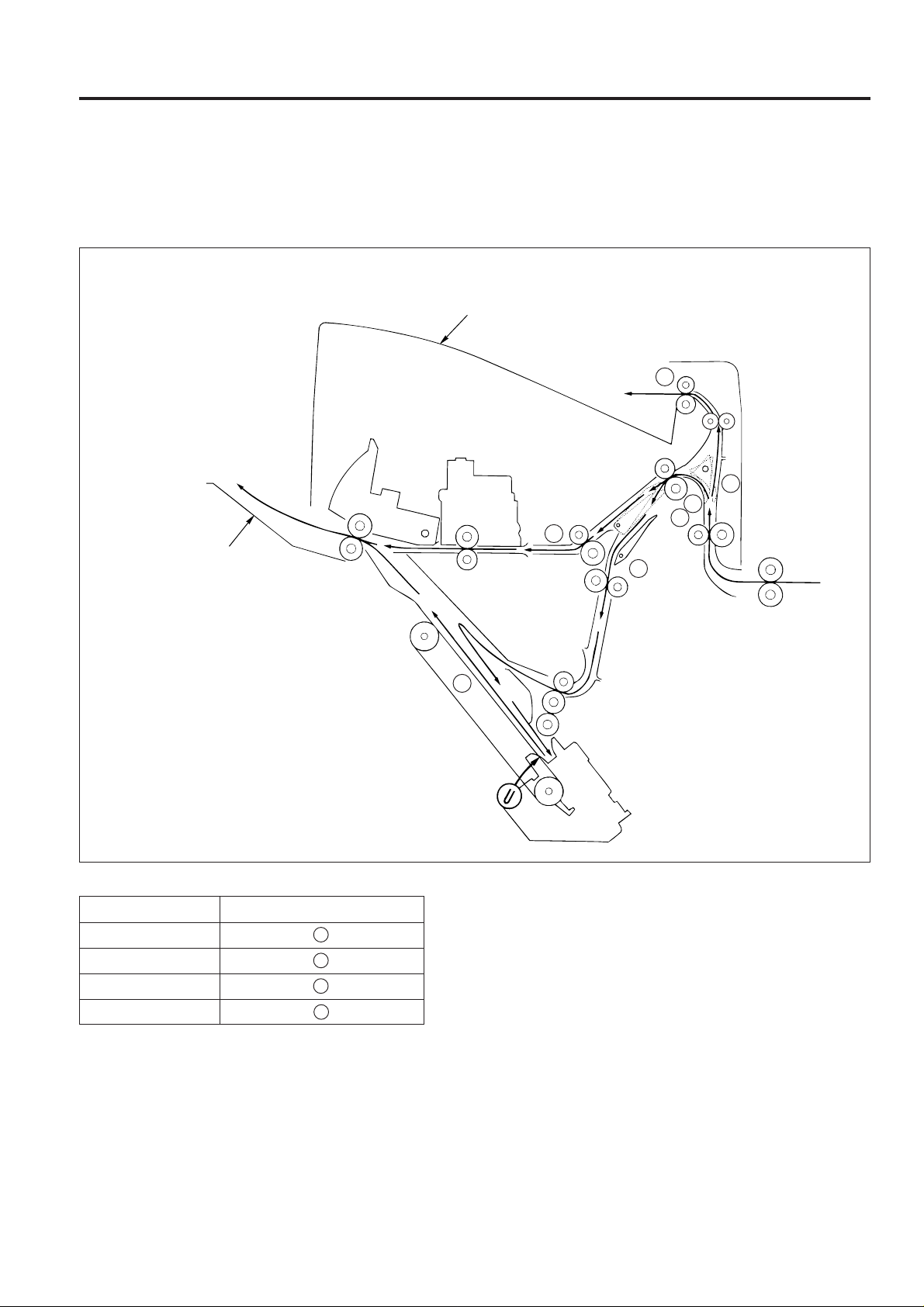
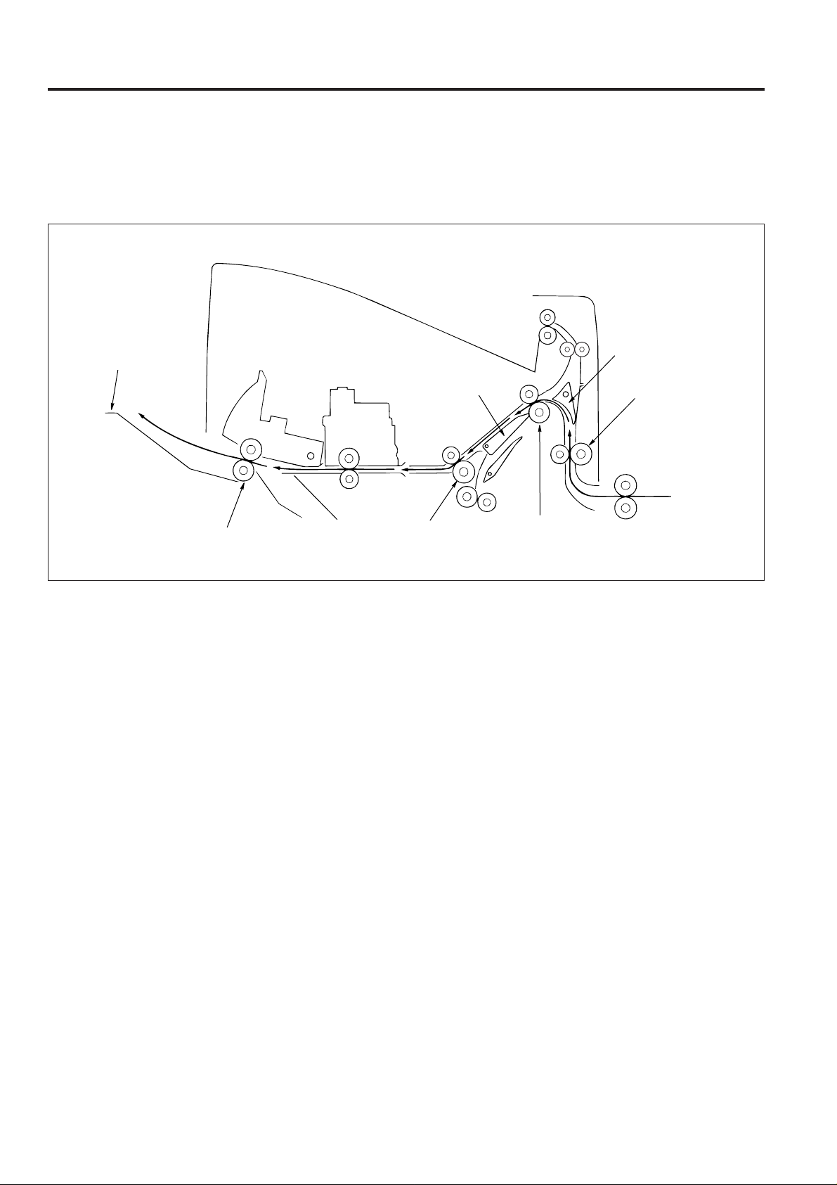
PAPER CONVEYANCE PATH
[1] Paper Conveyance Path
The FNS (Finisher) has three paper conveyance paths as shown in the diagram below.
Face up and face down operations are performed in the reversal paper exit section of the main body.
Sub-tray
2
1
1
Main tray
3
FS-106
2
3
Finishing Paper conveyance paths
Non-Sort mode 1
Sort/Group mode 1
Sub-tray mode 2
Staple mode 3
3
1 - 5
Page 9
FS-106
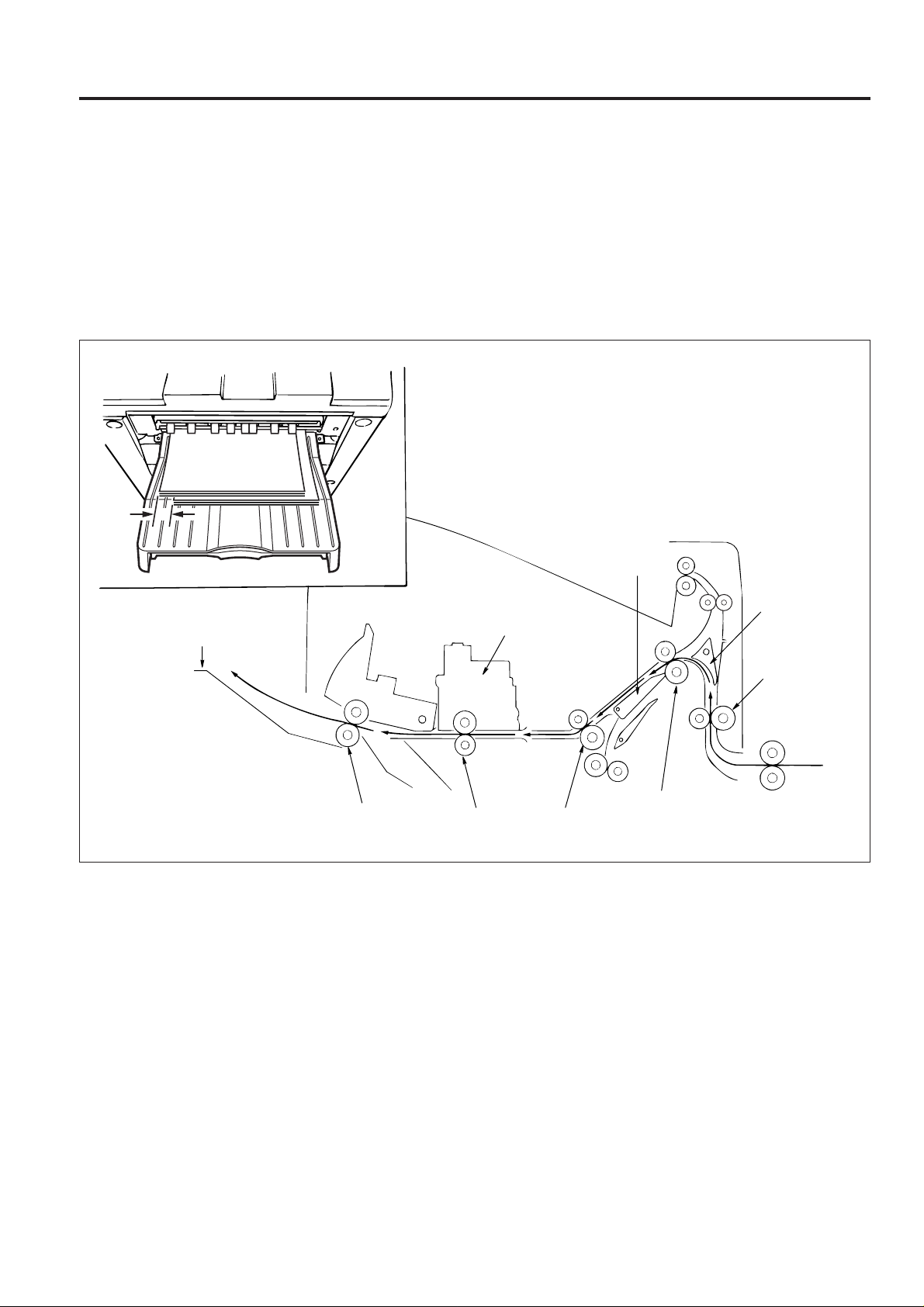
[2] Non-Sort mode
Exit to main tray
A paper exited from the main body is conveyed and exited to the main tray.
Main tray
Paper exit roller
Gate
Shift unit
Conveyance roller C
Sub-tray gate
Conveyance roller A
Conveyance roller B
1 - 6
Page 10
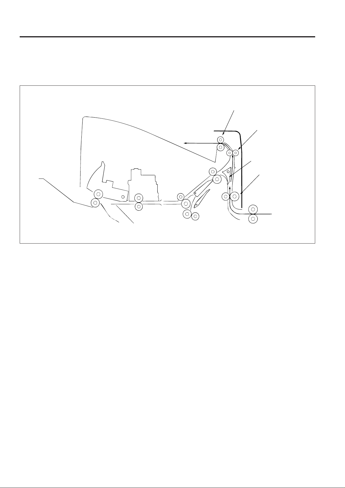
[3] Sort/Group mode
Exit to main tray
Paper exited from the main body is conveyed and exited to the main tray. This mode has an off-set function that allows each page
of the even-numbered sets to be exited with the paper shifted 30mm to the rear.
off-set function
(1) The odd-numbered pages are exited to the main tray with the image side face down.
(2) The even-numbered pages are shifted 30mm to the rear by the conveyance slide shaft of the shift unit and then
exited to the main tray.
30mm
FS-106
Main tray
Paper exit roller
Shift unit
Conveyance
slide shaft
Gate
Sub-tray gate
Conveyance roller A
Conveyance roller B
Conveyance roller C
1 - 7
Page 11
FS-106
[4] Sub-tray mode
The sub-tray gate opens. Paper exited from the main body is conveyed and exited to the sub-tray.
Paper exit roller
Sub-tray
Conveyance roller D
Sub-tray gate
Conveyance roller A
1 - 8
Page 12
FS-106
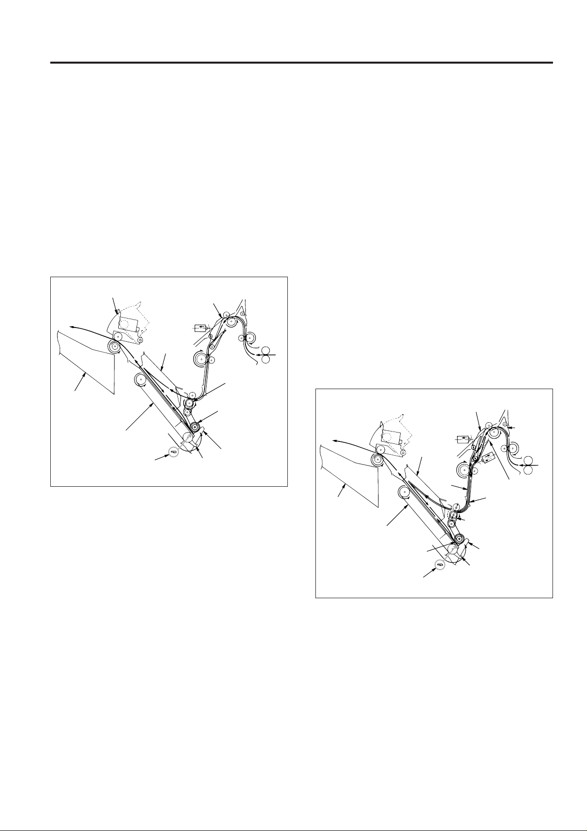
[5] Staple mode
(1) The gate switches to the staple mode.
(2) For A4R paper and above, the paper exit opening
opens.
(3) The first stack of paper is conveyed and stacked.
(a) The sponge roller of the stac ker section sends the
paper to the stopper and the paper is lined up in
the lengthwise direction.
(b) The alignment plate unit lines up paper in the width-
wise direction.
(c) Paper is stapled.
(d) The first stack is conveyed by the paper exit arm
and exited to the main tray.
Paper exit opening
1st stack
Alignment
plate unit
Main tray
Stacker
Stapler
Gate
Stacker
entrance roller
Sponge roller
Stopper
Paper
exit arm
(4) The second and subsequent stacks of paper are con-
veyed and stacked.
(a) The first page stops in the stacker entrance with
the by-pass gate opened. The stacker entrance
roller stops to wait for the previous stack to be
exited.
(b) The by-pass gate is closed and the second page
is stacked on top of the first.
(c) Once the previous stack has e xited, the stac k en-
trance roller rotates and the first and second pages
are simultaneously sent to the stacker.
• The above steps (a) to (c) are for paper to a maximum of A4 size.
(d) The sponge roller of the stack er section sends the
paper to the stopper and the paper is lined up in
the lengthwise direction.
(e) The alignment plate unit lines up paper in the width-
wise direction.
(f) When all paper is conv e yed to the stac k er, the pa-
per is stapled.
(g) The second and subsequent sets are conveyed
by the paper exit arm and the paper is exited to
the main tray.
2nd and
subsequent
stacks
Main tray
Alignment
plate unit
2nd
page
Gate
By-pass gate
1st page
Sub-tray
gate
1 - 9
Stacker
Sponge roller
Stacker entrance roller
Stopper
Paper exit arm
Stapler
Page 13
FS-106
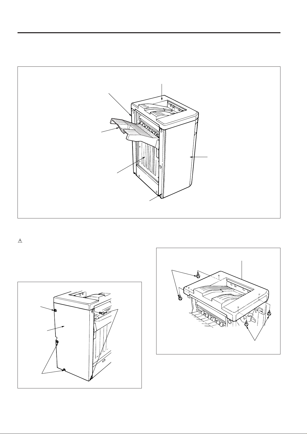
EXTERNAL SECTION
[1] Composition
Rear cover
Main tray
Paper exit
stopper plate
Top cover
Front cover
[2] Disassembly and Assembly
CAUTION
Be sure that the power cord has been unplugged from
the outlet.
1. Removing/installing the rear and top covers
a. Procedure
(1) Remove the 5 screws and remove the rear cover.
Screw
Rear cover
Screws
Front side cover
(2) Open the front cover.
(3) Remove the 4 screws and remove the top cover.
Top cover
Screws
Screws
Screws
(4) Reinstall the rear and top covers in the opposite se-
quence to removal.
1 - 10
Page 14
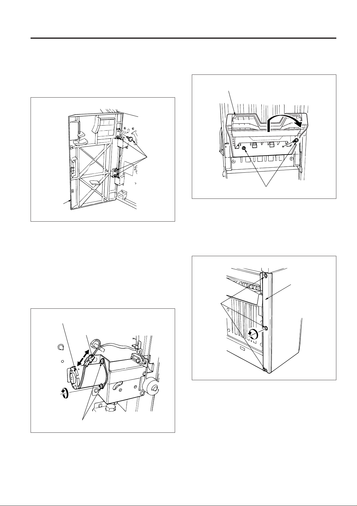
FS-106
2. Removing and installing the front cover
a. Procedure
(1) Open the front cover.
(2) Remove the 4 screws and remove the front cover.
Screws
Front cover
(3) Reinstall the front cover in the opposite sequence to
removal.
3. Removing and installing the main tray
a. Procedure
(1) Remove the rear cover.
(2) Remove the connector and the 2 screws, then remov e
the tray up-down motor (M3).
CAUTION: Take out the tray up-down motor while sup-
porting the main tray with your hand.
(3) Remove the 2 screws, lift up and remove the main tray.
Main tray
Screws
(4) Reinstall the shift tray in the opposite sequence to re-
moval.
4. Removing and installing the front side cover
a. Procedure
(1) Remove the 3 screws and remov e the front side cover .
Front side cover
Screws
Tray up-down motor (M3)
Connector
Screws
(2) Reinstall the front side cover in the opposite sequence
to removal.
1 - 11
Page 15
FS-106
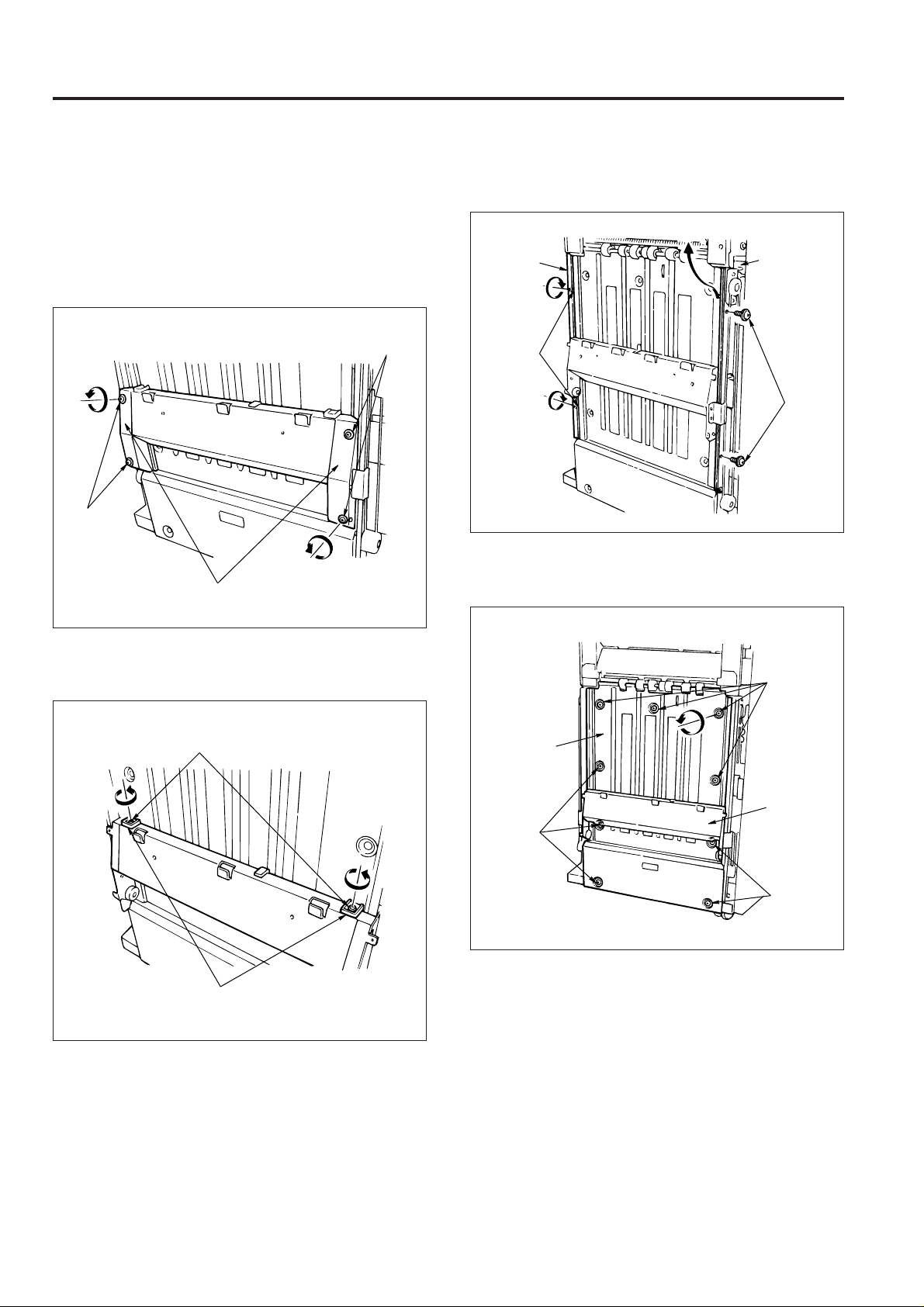
5. Removing and installing the paper exit stopper
plate
a. Procedure
(1) Remove the rear cover, main tray and the front side
cover.
(2) Remove the 4 screws and remove the left and right
up-down covers.
Screws
Screws
Up-down cover
(4) Remove the 2 screws and take out the up-down sup-
port plate (front and rear).
Up-down
support
plate (rear)
Screws
Up-down
support
plate (front)
Screws
(5) Remove the 9 screws, lift the up-down stay and take
out the paper exit stopper plate to the lower side.
(3) Remove the 2 screws and remove the 2 slide stop-
pers.
Screws
Slide stoppers
Screws
Paper exit
stopper plate
Up-down
stay
Screws
Screws
(6) Reinstall the paper exit stopper plate in the opposite
sequence to removal.
1 - 12
Page 16
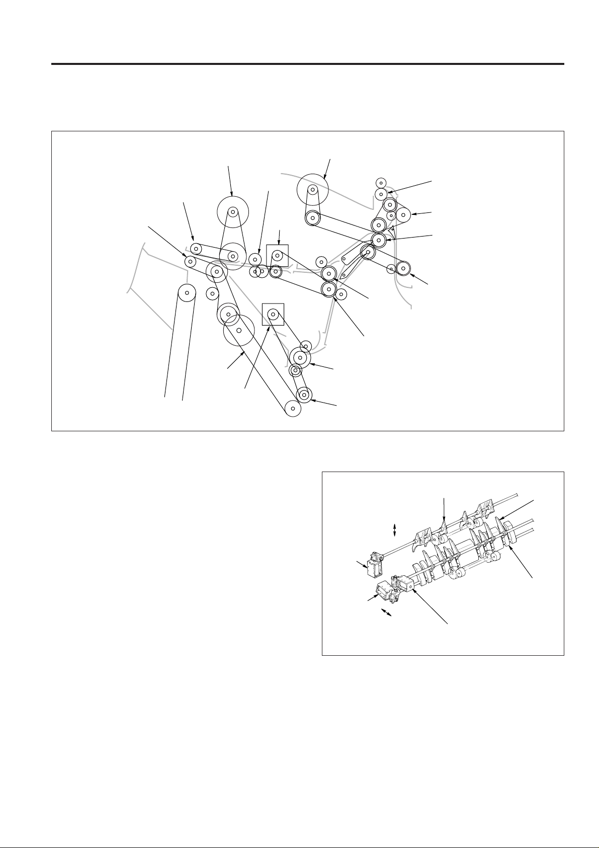
CONVEYANCE SECTION
[1] Composition
FS-106
Paper exit roller
(sponge roller)
Paper exit roller motor (M7)
Nip paper exit roller
Paper exit belt
Stacker entrance
Conveyance
motor (M14)
slide shaft
2nd
conveyance
motor (M4)
1st conveyance motor (M1)
Sub-tray paper exit roller
Conveyance roller D
Conveyance roller B
Conveyance roller A
Conveyance
roller C
Intermediate roller
Stacker entrance roller
Sponge roller
[2] Mechanism
1. Paper conveyance
Paper conveyance is performed by the conveyance rollers A,
B, C and D , the intermediate roller, conveyance slide shaft and
sub-tray paper exit roller . These components are driven b y the
1st conveyance motor (M1) and the 2nd conveyance motor
(M4) through the timing belt.
Stacking to the paper stacker is performed by the stacker
entrance roller and sponge roller. These are driven by the
stacker entrance motor (M14) via the timing belt.
Paper exiting is perfor med by the stacker paper exit belt arm
and the paper exit rollers. These are driven by the paper exit
motor (M7) via the timing belt.
2. Paper path switching
Sub-tray gate
Sub-tray
paper
exit
solenoid
(SD2)
By-pass
solenoid
(SD5)
OFF
ON
ON
OFF
Gate solenoid
(SD1)
The paper route switches using the gate, sub-tray gate and
by-pass gate. Each gate oper ates with the ON/OFF s witching
of the gate solenoid (SD1), sub-tray paper e xit solenoid (SD2)
and by-pass solenoid (SD5).
Gate
By-pass
gate
1 - 13
Page 17
FS-106
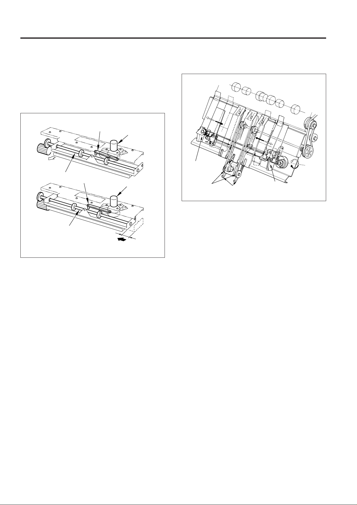
3. Shift unit sort shift operation
(1) The paper in the shift unit is fed in the exit direction by
the slide shaft.
(2) When the roller shift motor (M2) rotates, the link mecha-
nism shifts the paper along with the slide shaft, 30mm
towards the direction of the back side.
Shift unit
Exit direction
Slide shaft
Slide shaft
Link mechanism
Link mechanism
30mm towards the direction
of the back side
Roller shift
motor (M2)
Roller shift motor (M2)
4. Stacker unit
Alignment
plate
Paper exit belt
Paper exit arm
Alignment plate
Alignment
plate
motor
(M5)
Paper alignment
Paper in the stacker is lined up by the forward and reverse
movement of the alignment plates. The forward/re verse motion
of the alignment plates is performed by the alignment plate
motor (M5).
Paper exiting
The paper exit arm sends the stapled paper out to the paper
exit opening.
The paper exit belt is rotated by the paper exit roller motor
(M7).
1 - 14
Page 18
FS-106
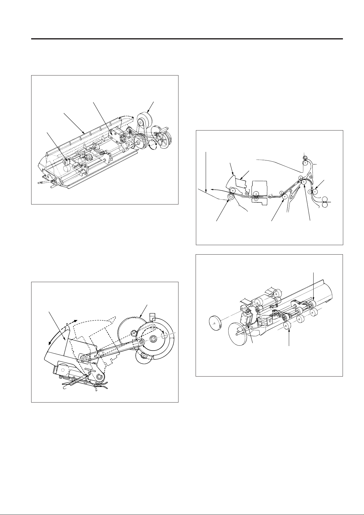
5. Paper exit opening unit
Paper exit opening
Paper exit
opening
Nip roller
solenoid (SD4)
Close Open
(1) Stapling mode for paper sized A4R and above
The paper exit opening is opened from the time copying commences to the time stapling is complete.
(2) Paper exit of the staple mode
When the stapling has finished, the paper exit opening is closed, the paper gripped and exited to the main
tray. The opening and closing of the paper exit opening is performed by the paper exit opening motor (M8).
Paper exit
opening motor
(M8)
(3) Pressure of the paper exit roller
The paper exit roller rotation is slower than the conveyance rollers A, B and C. Therefore pressure is released at times other than when paper is exiting.
When the paper reaches the paper exit opening the
paper exit roller applies pressure and paper is exited
to the main tray. The pressing and releasing of paper is
performed by the paper exit opening solenoid (SD4).
Main tray
Paper exit roller
Paper exit
opening
Paper exit
opening solenoid
(SD4)
Conveyance
roller C
Conveyance
roller B
Nip roller
Conveyance
roller A
Paper exit
opening
Close
Open
Paper exit
opening motor (M8)
Paper exit
opening
solenoid
(SD4)
Paper exit
roller
1 - 15
Page 19
FS-106
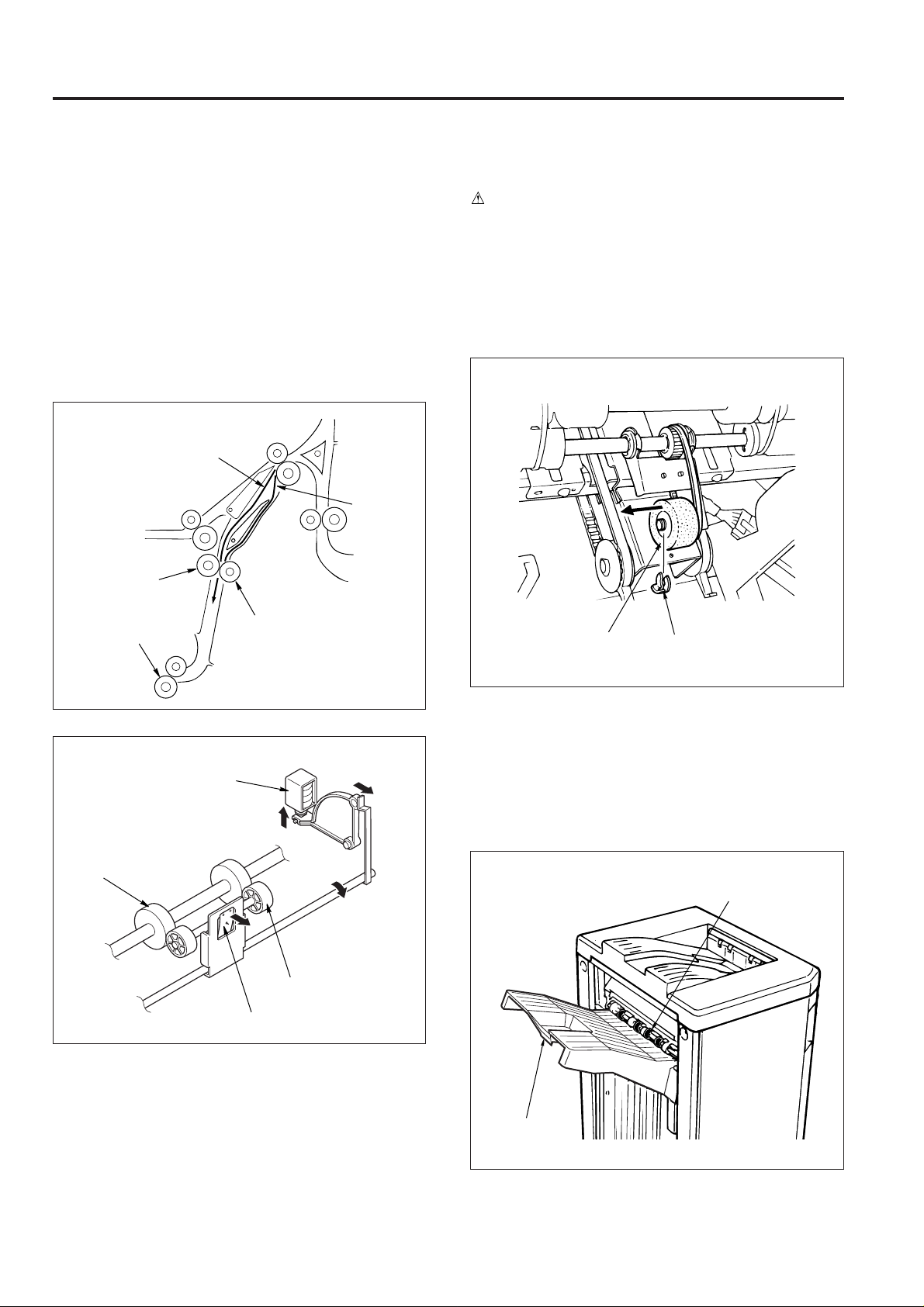
6. Intermediate conveyance roller
In this machine, in order to be compatible with thick paper ,
it has its pressure of the intermediate conveyance roller
set at a slightly higher level.
While in conve yance collectively of the 1st and 2nd copies
of the 2nd set and later to the stacker in staple copy mode
for small-sized paper, the decompression solenoid (SD3)
is operated to lower the pressure of the intermediate conveyance roller.
This is to prevent dirt from the roller from sticking to the
paper and wrinkles from taking place on paper in conveyance.
2nd copy
1st copy
Intermediate roller
[3] Disassembly and Assembly
CAUTION
Be sure to remove the power cord from the power
outlet.
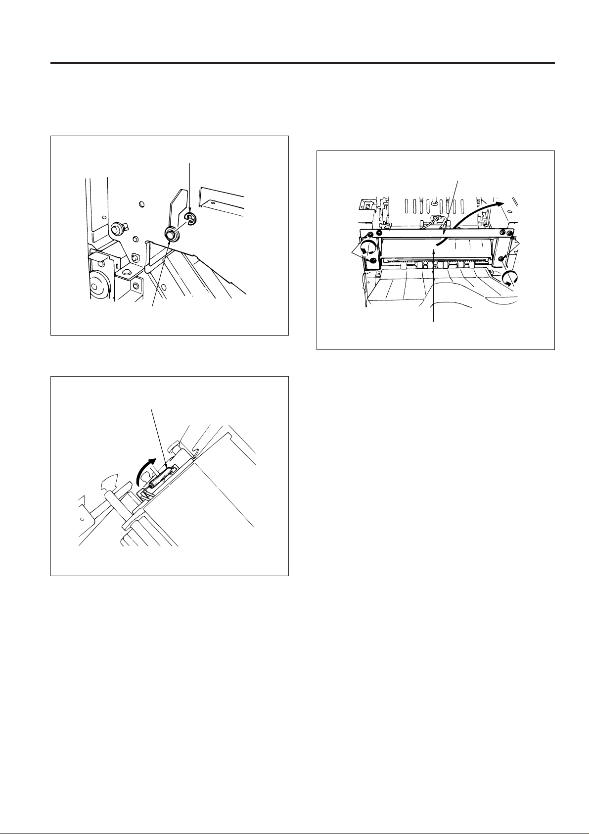
1. Exchanging the stacker unit section sponge
roller
a. Procedure
(1) Open the front cover, remove the fixing ring of the
stacker unit section and then remov e the sponge roller.
Stacker entrance roller
Decompression
solenoid (SD3)
Intermediate roller
Backup roller
Backup roller
Tension spring
Sponge roller
Fixing ring
(2) Reinstall the sponge roller in the opposite sequence
to removal.
2. Exchanging the paper exit roller (sponge roller)
a. Procedure
(1) Move the main tray down by using the 47 mode func-
tion (75-06 code).
Sponge rollers
1 - 16
Main tray
Page 20

FS-106
(2) Insert a screwdriver into the slot of the sponge roller,
then pry the roller open.
Sponge roller
(3) Align the grooves of the new sponge rollers with the
shaft.
(4) Press the sponge rollers until a click sounds, so that
they are properly installed.
3. Removing and reinstalling the shift unit
a. Procedure
(1) Remove the following parts:
• rear cover
• top cover
(2) Remove the connector of M2 and PS18.
(3) Remove the wiring from the three clamp positions.
Clamps
Wiring
M2 connector
(4) Remove the ground wire fixing screw.
(5) Remove the clamp screw.
(6) Remove the 4 screws, then remove the shift unit.
PS18
connector
Align
Align
Clamp screw
Screws
Ground wire
fixing screw
Shift unit
(7) Reinstall the shift unit in the opposite sequence to re-
moval.
Screws
1 - 17
Page 21
FS-106
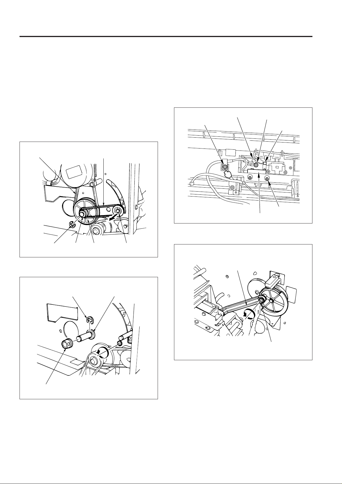
4. Removing and installing the paper exit
opening unit
a. Procedure
(1) Remove the following parts:
• rear cover
• top cover
• front side cover
• shift unit
(2) Remove the pulley and belt.
(3) Remove the E-ring and then remove the collar, gear
and drive belt.
Drive belt
Belt
(5) Remove the clamp screw and the ground wire screw.
(6) Remove the connector of SD4 and PS6.
(7) Remove a set screw and withdraw the PS23 from the
unit, then remove the connector.
Note: When withdrawing the PS23, ensure that needless
force is not applied to the lever below the PS23.
SD4 connector
Clamp screw
Ground wire screw
PS6 connector
Screw for PS23
SD23
E-ring
Collar
Gear
Pulley
(4) Remove the collar, E-ring and shaft holder.
E-ring
Collar
Shaft holder
(8) Remove the paper exit opening open-shut link screw.
Paper exit opening
open-shut link
Screw
1 - 18
Page 22
FS-106
(9) Open the front cover and remove the front side E-ring
and shaft holder.
E-ring
Shaft holder
(10)Remove the spring.
(11)Remove the 4 screws and then remove the paper exit
opening cover.
(12)Take the paper exit opening unit out to the top.
Paper exit
opening cover
Screws
Screws
Paper exit
opening unit
(13) Reinstall the paper exit opening unit in the opposite
sequence to removal.
Spring
1 - 19
Page 23

FS-106
5. Removing/installing the stacker unit
a. Procedure
(1) Remove the following parts:
• rear cover
• top cover
• front side cover
(2) Take out the E-ring and flange, then remove the belt
and the two pulleys.
(3) Remove the shaft with a screwdriver and remove the
belt detection gear.
Belt
Belt detection
gear
Pulley E-ring Flange
Shaft
Pulley
(4) Remove the four connectors (CN1, CN5, CN11, CN12)
on the FNS control board.
CN5
CN11
CN1
FNS control
board
CN12
(5) Remove the four set screws , then remove the con vey-
ance unit.
Note: When placing the conveyance unit on the floor, etc.,
ensure that it is placed upside down.
Set screws
Set screw
Set screw
Conveyance unit
1 - 20
Page 24

FS-106
(6) Remove the E-ring and then shift the shaft holder.
Shaft
holder
E-ring
(7) Shift the shaft holder and then remove the shaft.
(8) Remove the connector of PS9 and then remove the
wiring from the clamp.
PS9 connector
Clamp
(9) Remove the screw and then remove PS9.
Shaft
Shaft holder
Screw
Clamp
PS9
1 - 21
Page 25

FS-106
(10)Remove CN6 and CN3 on the FNS control board and
the stapler F and R connectors. Then remove the
wiring from the clamp.
FIN control board
CN6
CN3
Clamps
Stapler F
connector
Stapler R connector
(11) Remove the 4 screws and then remove the stacker
unit.
Screws
CAUTION:
1. When the stacker paper exit arm is in the position as
that of the diagram, engage the gear so that the notch
of the detection gear actuator meets with the edge of
PS9 as per the diagram below.
Belt detection gear
Stacker paper
exit arm
Actuator
PS9
Actuator notch
2. When reinstalling the stacker unit, be careful not to
damage the conveyance guide sheets on the stacker
unit guide plate.
Screws
Stacker unit
(12)Reinstall the stacker unit in the opposite sequence to
removal.
Conveyance guide sheet
Conveyance
unit
Stacker unit guide plate
1 - 22
Page 26

FS-106
[4] M1 (1st conveyance) Control
P.GND
101-4
P.GND
101-5
S.GND
101-3
5V
101-2
114-1
TXD
114-2
DTR
114-6
RTS
114-3
RXD
114-7
DSR
114-5
CTS
101-1
24V
MAIN BODY
MS1
The 1st conveyance control during main tray paper exit and the
paper exit control during sub-tray paper exit are done by
transmitting the rotation of M1 (1st conveyance) to conveyance
rollers (A), (B), (D), and to the sub-tray paper exit roller.
FNS CB (FNS control board) controls M1.
1. Operation
a. Interlock
Paper 1st conveyance control commences with the ON
signal from the main body start button. However, if MS1
(interlock) is OFF, error data will be output to the main body
CB and control will not commence.
9-3
9-4
9-5
9-7
10-1
10-2
10-3
10-4
10-5
10-6
9-1
RXD
CTS
DSR
TXD
RTS
DTR
24V-IN
M1 BLK
M1 CONT
M1 CLK
M1DIR
24V GND
24V GND
PS4 IN
PS1 IN
FNS CB
VCC
24V
24V
24V
VCC
GND
GND
5-A1
5-B10
5-B9
5-B8
5-B11
1-A1
1-A2
1-A3
1-A5
1-A6
5-A3
5-A8
5-B4
5V
5-A5
5-B6
5-A7
M1
PS4
PS1
b. M1 (1st conveyance) Control
(1) Main tray paper exit operation
M1 (1st conveyance) turns ON by the ON signal of the
start button and goes OFF after the specified time
when PS4 (FIN entrance path) detects the trailing edge
of the final copy.
(2) Sub-tray paper exit operation
M1 turns ON by the ON signal of the start button, and
rotates at high speed. When PS4 (FIN entrance path)
detects the trailing edge of the paper, rotation switches
to low speed after the specified time. Then, rotation
once again returns to high speed to be ready for
conveyance of the next copy. On detection of the
trailing edge of the final copy by PS4, it turns OFF in the
specified time.
M1 (1st convenyance)
PS1 (sub-tray upper limit)
Sub-tray
paper exit roller
Conveyance
roller D
Conveyance
roller B
PS4
(FIN entrance path)
Conveyance roller A
c. Sub-tray Upper Limit Detection Control
PS1 (sub-tray upper limit) is fitted in the sub-tray, and when
PS1 turns ON by detecting paper during sub-tray paper
exit, the main body and the FNS stop after ejecting the
paper being copied at that time.
2. Signals
a. Input signals
(1) TXD (main body CB FNS CB)
This is a serial data line to transmit the operational
state of the main body CB to the FNS CB.
(2) DTR (main body CB
FNS CB)
Transmission acknowledgement signal from the main
body to FNS.
(3) RTS (main body CB
FNS CB)
Request-to-send signal from the main body to FNS.
(4) 24 V IN (MS1
FNS CB)
When MS1 (interlock) goes ON, +24 V is output. This
power supply is supplied to each electrical load of FNS.
1 - 23
Page 27

FS-106
(5) PS1 IN (PS1 FNS CB)
When the sub-tray is full, PS1 (sub-tray upper limit)
goes ON and inputs [L].
(6) PS4 IN (PS4
FNS CB)
When paper passes through the FNS entrance, this
signal turns ON and [L] is input.
b. Output signals
(1) TXD (FNS CB main body CB)
This is a serial data line to transmit the operational
state of the main body CB to the FNS CB.
(2) RTS (FNS CB
Transmission acknowledgement signal from the main
body to FNS.
(3) DTR (FNS CB
Request-to-send signal from the main body to FNS.
(4) M1 CONT (FNS CB
Operational signal used by M1 (1st conveyance). M1
turns ON at the same time as the finisher operation
start signal.
[H]: OFF
[L]: ON
(5) M1 BLK (FNS CB
M1 (1st conveyance) brake signal.
[H]: OFF
[L]: ON
(6) M1 CLK (FNS CB
M1 (1st conveyance) speed adjustment clock.
(7) M1 DIR (FNS CB
M1 (1st conveyance) rotation direction signal.
[H]: Forward rotation (CW)
[L]: Reverse rotation (CCW)
main body CB)
main body CB)
M1)
M1)
M1)
M1)
[5] M4 (2nd conveyance) Control
P.GND
101-4
P.GND
101-5
S.GND
101-3
5V
101-2
TXD
114-1
DTR
114-2
RTS
114-6
RXD
114-3
DSR
114-7
CTS
114-5
24V
101-1
MAIN BODY
MS1
The 2nd convey ance control during main tray paper exit is done
by transmitting the rotation of M4 (2nd conveyance) to the
intermediate roller, conve yance roller (C), and the conv eyance
slide shaft.
FNS CB (FNS control board) controls M4 only when the main
tray paper exit is operated in the sort/group/non-sort/staple
mode.
1. Operation
Nip paper exit roller
9-3
9-4
9-5
9-7
10-1
10-2
10-3
10-4
10-5
10-6
9-1
RXD
CTS
DSR
TXD
RTS
DTR
24V-IN
M4 DRV A
M4 DRV A
M4 DRV B
M4 DRV B
PS4-IN
SD3 DRV
PS6-IN
FNS CB
24V
24V
VCC
GND
24V
GND
Conveyance slide roller
M4 (2nd conveyance)
12-1
12-6
12-2
12-3
12-4
12-5
5-A3
5-A8
5-B4
1-A9
1-A8
5V
5-A6
5-B7
5-A10
M4
PS4
SD3
PS6
Stacker entrance roller
a. During Sort/Group/Non-Sort Mode
M4 (2nd conveyance) turns ON by the ON signal of the start
button, and rotates at high speed. When PS4 (FIN entrance path) detects the trailing edge of the paper fed from
the main body, rotation switches to low speed after the
specified time.
Then, rotation once again returns to high speed to be ready
for conveyance of the next copy. On detection of the trailing
edge of the final copy by PS4, it turns OFF in the specified
time.
1 - 24
Conveyance
roller (C)
Intermediate roller
PS4 (FIN entrance
path)
Page 28

FS-106
b. During Staple Mode
(1) ON timing of M4 (2nd conveyance)
M4 (2nd conveyance) goes ON by the ON signal of
the start button, and rotates at high speed. When PS4
(FIN entrance path) detects the trailing edge of the
paper fed from the main body, rotation switches to low
speed after the specified time.
Then, rotation once again returns to high speed to be
ready for conveyance of the next copy.
(2) Paper conveyance of the 1st copy of the 2nd and later
sets
When PS4 (FIN entrance path) detects the trailing edge
of the 1st copy fed from the main body, it goes OFF
after the specified time, and enters a standby mode to
convey the 2nd copy.
As a result, the 1st copy is conveyed to the stacker
entrance.
(3) Paper conveyance of the 2nd copy of the 2nd and later
sets
When PS4 detects the trailing edge of the 2nd copy,
M4 starts to rotate at high speed after the specified
time. Then, in the specified time from detection of the
trailing edge of the 2nd copy by PS4, M4 is switched
over into low speed rotation.
Further, in the specified time, it once again returns to
high speed rotation which is the standby state for conveyance of the 3rd copy and later.
For the 3rd copy and later, rotation is switched over
into low speed in the specified time after the trailing
edge of the copy is detected by PS4, and is returned
to high speed in the specified time.
(4) OFF timing of M4 (2nd conveyance)
M4 turns OFF in the specified time after PS6 (paper
exit 1) detects the final set stapled.
c. Pressing Release Operation of Intermediate
Roller
The intermediate roller, when conveying the 1st and 2nd
copies of the 2nd set on collectively in staple copy mode
for A4/B5 paper, operates SD3 (decompression) and release its pressing, reducing pressing force of the roller.
SD3 turns ON after PS4 detects the trailing edge of the 1st
copy of the 2nd and later sets, and then goes OFF in the
specified time after the trailing edge of the 2nd copy of the
2nd and later sets is detected by PS4.
2. Signal
a. Input signals
(1) TXD (main body CB FNS CB)
This is a serial data line to transmit the operational
state of the main body CB to the FNS CB.
(2) DTR (main body CB
Transmission acknowledgement signal from the main
body to FNS.
(3) RTS (main body CB
Request-to-send signal from the main body to FNS.
(4) 24V IN (main body CB
+24V is output when MS1 (interlock) is turned ON.
This power is supplied to each load of FNS.
(5) PS4 IN (main body CB
When paper passes through the FNS entrance, this
signal turns ON and [L] is input.
(6) PS6 IN (PS6
When paper passes through the paper exit opening
to the main tray, this signal turns ON and [L] is input.
FNS CB)
FNS CB)
FNS CB)
b. Output signals
(1) TXD (FNS CB main body CB)
This is a serial data line to transmit the operational
state of the main body CB to the FNS CB.
(2) RTS (FNS CB
Transmission acknowledgement signal from the main
body to FNS.
(3) DTR (FNS CB
Request-to-send signal from the main body to FNS.
(4) M4 DRV A/M4 DRV B (FNS CB
M4 (2nd conveyance) drive signal.
(5) SD3 DRV (FNS CB
SD3 (decompression) drive use signal.
[H]: SD3 OFF
[L]: SD3 ON
main body CB)
main body CB)
SD3)
FNS CB)
FNS CB)
M4)
1 - 25
Page 29

FS-106
[6] Gate Control
P.GND
101-4
P.GND
101-5
S.GND
101-3
5V
101-2
TXD
114-1
DTR
114-2
RTS
114-6
RXD
114-3
DSR
114-7
CTS
114-5
24V
101-1
MAIN BODY
MS1
The paper conveyance path is switched by the ON/OFF
switching of SD1 (gate), SD2 (sub-tray paper exit) and SD5
(by-pass). The FNS CB (FNS control board) controls the ON/
OFF switching of SD1, SD2 and SD5.
1. Operation
PS6
(paper exit 1)
9-3
9-4
9-5
9-7
SD1 DRV
1-B5
24V
SD2 DRV
24V
SD5 DRV
24V
VCC 5-A3
PS4-IN 5-A8
GND 5-B4
VCC 5-A4
PS5-IN
GND
5V
GND
PS6-IN
1-B6
1-B7
1-B8
1-B11
1-B12
5-A9
5-B5
5-A6
5-B7
5-A10
10-1
10-2
10-3
10-4
10-5
10-6
9-1
RXD
CTS
DSR
TXD
RTS
DTR
24V-IN
FNS CB
SD2 (sub-tray paper exit)
Sub-tray paper exit roller
SD1 (gate)
PS5 (stacker
conveyance
path)
SD5 (by-pass)
SD1
SD2
SD5
PS4
PS5
PS6
b. Main tray paper exit operation (during staple
mode)
Paper is fed to the main tray via the stacker. At this time,
the paper passes the sub-tray gate, gate, and the b y-pass
gate as its convey ance path. Among these gates, the subtray gate is installed so that the stack er side becomes the
convey ance path beforehand, thus SD2 does not oper ate.
(1) SD1 (gate) ON timing
SD1 goes ON by the ON signal of the start button,
switches the gate to the stacker side, and enter a
standby mode for paper conveyance.
(2)
Paper conv ey ance f or paper in sizes other than A4/B5
Paper in sizes other than A4/B5 is conveyed to the
stacker side by the gate. At this time, SD5 does not
operate and the paper is fed to the stacker entrance
roller.
(3) A4/B5 sized paper conveyance (Conveyance of the
1st copy of the 2nd and later batches)
For conve y ance of A4 or B5 sized paper, in the specified time after the trailing edge of the final copy of the
preceding set is detected by PS4 (FIN entrance path),
SD5 is turned ON, switching the bypass gate into Bypass. The 1st copy of the following set is, therefore,
guided into the bypass track.
(4) A4/B5 sized paper conveyance (Conveyance of the
2nd copy of the 2nd and later sets)
In the specified time after the trailing edge of the 1st
copy is detected by PS4, SD5 turns OFF, closing the
bypass gate.
The 2nd copy, therefore, follows the normal course,
which is conveyed to the stacker entrance roller together with the 1st copy held in the bypass track.
The 3rd copy and later are conv e y ed to the stacker in
the normal course, where SD5 never turns ON.
(5) OFF timing of SD1 (gate)
SD1 turns OFF in the specified time after PS6 (paper
exit 1) detects the final set stapled.
PS4 (FIN entrance
path)
Stacker entrance
roller
a.
Main tray paper exit operation (during sort/group/
non-sort mode)
Paper is fed to the main tr a y via the shift unit. At this time,
the paper passes the sub-tray gate and the gate as its
conveyance path. These gates, however, are installed so
that the shift unit side becomes the conve yance path during idling state, so SD2 (sub-tray paper exit) and SD1 (gate)
which drive each gate do not operate.
1 - 26
Page 30

FS-106
c. Operation to exit to sub-tray
SD2 (sub-tray paper exit) turns ON with the start button ON
signal and the sub-tray gate to the sub-tray side.
When PS4 (FIN entrance path) detects the trailing edge of
the final copy, SD2 goes OFF after the specified time.
Finishing
Sort / Group / Non-sort
First page of
Staple-A4 • B5
(Other)
Sub-tray paper exit
second and
subsequent sets
Other
SD1
OFF
ON
ON
OFF
SD2
OFF
OFF
OFF
ON
2. Signals
a. Input signals
(1) TXD (main body CB FNS CB)
This is a serial data line to transmit the operational
state of the main body CB to the FNS CB.
(2) DTR (main body CB
Transmission acknowledgement signal from the main
body to FNS.
(3) RTS (main body CB
Request-to-send signal from the main body to FNS.
(4) PS4 IN (PS4
This signal turns ON when the paper passes the FNS
entrance and [L] is input.
(5) PS5 IN (PS5
This goes ON when the paper passes the stacker entrance and [L] is input.
(6) PS6 IN (PS6
This signal turns ON when the paper passes the main
tray paper exit opening and [L] is input.
FNS CB)
FNS CB)
FNS CB)
FNS CB)
FNS CB)
SD5
OFF
ON
(OFF)
OFF
OFF
b. Output signals
(1) TXD (FNS CB main body CB)
This is a serial data line to transmit the operational
state of the main body CB to the FNS CB.
(2) RTS (FNS CB
Transmission acknowledgement signal from the main
body to FNS.
(3) DTR (FNS CB
Request-to-send signal from the main body to FNS.
(4) SD1 DRV (FNS CB
SD1 (gate) drive use signal.
[H]: OFF
[L]: ON
(5) SD2 DRV (FNS CB
SD2 (sub-tray) drive use signal.
[H]: OFF
[L]: ON
(6) SD5 DRV (FNS CB
SD5 (by-pass) drive use signal.
[H]: OFF
[L]: ON
main body CB)
main body CB)
SD1)
SD2)
SD5)
1 - 27
Page 31

FS-106
[7] M14 (Stacker Entrance) Control
P.GND
101-4
P.GND
101-5
S.GND
101-3
5V
101-2
TXD
114-1
DTR
114-2
RTS
114-6
RXD
114-3
DSR
114-7
CTS
114-5
24V
101-1
MAIN BODY
MS1
M14 (stacker entrance) drives the stacker entrance roller and
the sponge roller. These rollers allow paper conveyance to
the stacker , aligning the tr ailing ends of pages, and adjust the
timing of staple standby.
FNS CB (FNS control board) controls M14.
1. Operation
The operation to convey paper to the stacker differs between paper of A4/B5 sizes and other sizes.
PS6 (paper exit 1)
M14 (stacker entrance)
9-3
9-4
9-5
9-7
10-1
10-2
10-3
10-4
10-5
10-6
9-1
RXD
CTS
M14 DRV A
DSR
M14 DRV A
TXD
M14 DRV B
RTS
M14 DRV B
DTR
24V-IN
FNS CB
PS5
(stacker
conveyance
path)
VCC
PS4 IN
GND
VCC
PS5 IN
GND
GND
PS6-IN
7-1
24V
7-6
24V
7-2
7-3
7-4
7-5
5-A3
5-A8
5-B4
5-A4
5-A9
5-B5
5V
5-A6
5-B7
5-A10
Stacker entrance
roller
Sponge roller
M14
PS4
PS5
PS6
PS4 (FIN entrance
path)
Then, in the specified time after the trailing edge of
paper is detected by PS5 (stacker conveyance path),
it returns to high speed rotation once again, entering
standby state for conveyance of the following copy.
Through repetition of these operations, sheets of paper are carried successively to the stacker section.
(2) OFF timing of M14
M14 turns OFF in the specified time after PS6 (paper
exit 1) detects the final batch stapled.
b. Conveyance operation to the stacker (A4/B5
sizes)
(1) Paper conveyance for the 1st set
A4/B5 sized sheets of paper for the 1st batch to staple
are fed in the same way as those other than A4/B5
sized.
(2) Paper conveyance of the 1st copy of the 2nd and later
sets
M14 turns OFF in the specified time after the trailing
edge of this paper is detected by PS4 (FIN entrance
path). The 1st copy, therefore, is held in standby in
the by-pass track so that paper of the 2nd set is not
conveyed to the stacker section before completing to
staple the first set.
(3) Paper conveyance of the 2nd copy of the 2nd and later
sets
M14 turns ON again in low speed in the specified time
after the trailing edge of this paper is detected by PS4.
Therefore, the 1st and 2nd copies are collectively conveyed to the stacker section as being piled up. In the
specified time after PS5 (stacker conveyance path)
detects the trailing edges of the 1st/2nd copies, M14
changes into high speed rotation, entering standby
state for conveyance of the following copy.
The 3rd and later copies are conveyed to the stacker
section in the same manner as that for the 1st.
c. Operation for justifying the trailing edge of the
paper
The trailing edge of the paper conveyed to the stacker are
aligned by the sponge roller one at a time.
a. Conveyance operation to the stacker (sizes
other than A4/B5)
(1) M14 (stacker entrance) ON timing
M14 (stacker entrance) turns ON with input of ON signal by the start button and, rotates at high speed.
Rotation switches into low speed in the specified time
after the trailing edge of paper is detected by PS4 (FIN
entrance path).
1 - 28
Page 32

FS-106
2. Signals
a. Input signals
(1) TXD (main body CB FNS CB)
This is a serial data line to transmit the operational
state of the main body CB to the FNS CB.
(2) DTR (main body CB
FNS CB)
Transmission acknowledgement signal from the main
body to FNS.
(3) RTS (main body CB
FNS CB)
Request-to-send signal from the main body to FNS.
(4) PS4 IN (PS4
FNS CB)
This signal turns ON when paper passes the FNS
entrance and [L] is output.
(5) PS5 IN (PS5
FNS CB)
This signal turns ON when paper passes the stacker
entrance and [L] is output.
(6) PS6 IN (PS6
FNS CB)
This signal turns ON when the paper passes the main
tray paper exit opening and [L] is input.
b. Output signals
(1) TXD (FNS CB main body CB)
This is a serial data line to transmit the operational
state of the main body CB to the FNS CB.
(2) RTS (FNS CB
Transmission acknowledgement signal from the main
body to FNS.
(3) DTR (FNS CB
Request-to-send signal from the main body to FNS.
(4) M14 DRV A, A
M14 (stacker entrance) drive use signal.
main body CB)
main body CB)
/M14 DRV B, B¯ (FNS CB M14)
¯
[8] M5 (Alignment Plate) Control
P.GND
101-4
P.GND
101-5
S.GND
101-3
5V
101-2
TXD
114-1
DTR
114-2
RTS
114-6
RXD
114-3
DSR
114-7
CTS
114-5
24V
101-1
MAIN BODY
MS1
The alignment of the widthwise direction of paper conveyed
to the stacker is performed by the opening and closing of
the alignment plate by M5 (alignment plate). M5 is controlled
by FNS CB (FNS control board).
1. Operation
In the initial operation, the alignment plate is stopped in the
position where PS8 (alignment plate HP) is ON. After the
specified time from when PS5 (stacker conveyance path)
detected the trailing edge of the paper, M5 (alignment
plate) rotates, and closes the alignment plate which opens
after the specified time. This operation is performed for
each page.
9-3
9-4
9-5
9-7
10-1
10-2
10-3
10-4
10-5
10-6
9-1
RXD
CTS
DSR
TXD
RTS
DTR
24V-IN
M5 DRV A
M5 DRV A
M5 DRV B
M5 DRV B
PS5 IN
PS8 IN
FNS CB
24V
24V
VCC
GND
VCC
GND
6-A12
6-B12
3-5
3-6
3-7
3-8
5-A4
5-A9
5-B5
6-A1
6-A8
6-B4
M5
PS5
PS8
1 - 29
Alignment
plate
PS5 (stacker
conveyance
path)
M5 (alignment plate)
Page 33

FS-106
2. Signals
a. Input signals
(1) TXD (main body CB FNS CB)
This is a serial data line to transmit the operational
state of the main body CB to the FNS CB.
(2) DTR (main body CB
FNS CB)
Transmission acknowledgement signal from the main
body to FNS.
(3) RTS (main body CB
FNS CB)
Request-to-send signal from the main body to FNS.
(4) PS5 IN (PS5
FNS CB)
This signal turns ON when the paper passes the
stacker entrance and [L] is output.
(5) PS8 IN (PS8
FNS CB)
When this signal detects alignment plate home
position, [L] is output.
b. Output signals
(1) TXD (FNS CB main body CB)
This is a serial data line to transmit the operational
state of the main body CB to the FNS CB.
(2) RTS (FNS CB
Transmission acknowledgement signal from the main
body to FNS.
(3) DTR (FNS CB
Request-to-send signal from the main body to FNS.
(4) M5 DRV A/M5 DRV B (FNS CB
M5 (alignment plate) drive use signal.
main body CB)
main body CB)
M5)
[9] M2 (Roller Shift) Control
P.GND
101-4
P.GND
101-5
S.GND
101-3
5V
101-2
TXD
114-1
DTR
114-2
RTS
114-6
RXD
114-3
DSR
114-7
CTS
114-5
24V
101-1
MAIN BODY
MS1
Paper shift for sort and group modes is performed by M2
(roller shift). The control of M2 is performed by the FNS CB
(FNS control board).
1. Operation
In the specified time after the trailing edge of the paper
subject to shifting is detected by PS4 (FIN entrance path)
in Sort/Group mode, M2 (roller shift) turns ON.
Rotation of M2 starts shifting of the conveyance slide shaft.
The conveyance slide shaft is rotated by M4 (2nd conveyance) driving, which shifts as conveying paper.
When PS18 (roller shift HP) turns ON and detects completion of shifting of the conveyance slide shaft, M2 turns OFF
and is brought to a stop.
In the specified time from turning OFF of PS4, M2 turns ON
once again, returning the conveyance slide shaft to the
original position. When PS18 turns OFF and the conveyance slide shaft returns fully to the original position, M2 is
brought to a stop, where it waits for the next paper subject
to shifting.
Through repetition of these operations, sheets of paper are
shifted and conveyed to the paper exit roller.
9-3
9-4
9-5
9-7
10-1
10-2
10-3
10-4
10-5
10-6
9-1
RXD
CTS
DSR
TXD
RTS
DTR
24V-IN
M2 DRV
PS18 IN
FNS CB
P.GND
VCC
PS4 IN
GND
GND
1-B1
1-B2
5-A3
5-A8
5-B4
5-A6
5V
5-B1
5-B7
M2
PS4
PS18
1 - 30
Page 34

[10] M7 (Paper Exit Roller) Control
FS-106
M2 (roller shift)
Conveyance slide shaft
Paper exit roller
2. Signals
a. Input signals
(1) TXD (main body CB FNS CB)
This is a serial data line to transmit the operational
state of the main body CB to the FNS CB.
(2) DTR (main body CB
FNS CB)
Transmission acknowledgement signal from the main
body to FNS.
(3) RTS (main body CB
FNS CB)
Request-to-send signal from the main body to FNS.
(4) PS4 IN (PS4
FNS CB)
This signal turns ON once the paper passes the
FNS entrance and [L] is output.
(5) PS18 IN (PS18
FNS CB)
Roller shift position detection signal.
[L]
[H]: Front position
[H]
[L]: Rear position
b. Output signals
(1) TXD (FNS CB main body CB)
This is a serial data line to transmit the operational
state of the main body CB to the FNS CB.
(2) RTS (FNS CB
Transmission acknowledgement signal from the main
body to FNS.
(3) DTR (FNS CB
Request-to-send signal from the main body to FNS.
(4) M2 DRV (FNS CB
M2 (roller shift) drive use signal.
[H]: M2 ON
[L]: M2 OFF
main body CB)
main body CB)
M2)
PS4 (FIN entrance path)
PS18 (roller shift HP)
P.GND
P.GND
S.GND
5V
TXD
DTR
RTS
RXD
DSR
CTS
24V
MAIN BODY
MS1
101-4
101-5
101-3
101-2
114-1
114-2
114-6
114-3
114-7
114-5
101-1
9-3
9-4
9-5
9-7
10-1
10-2
10-3
10-4
10-5
10-6
9-1
RXD
CTS
DSR
TXD
RTS
DTR
24V-IN
24V GND
M7 CONT
M7 CLK
M7 GAIN
PS23 IN
FNS CB
24V
VCC
GND
GND
PS9 IN
GND
1-A4
1-A7
5-A2
5-B2
1-A11
1-A10
1-A12
5V
11-1
11-2
11-3
5V
6-A2
6-A9
6-B5
M7
PS23
PS9
Paper exit from the stacker is performed by the paper exit
belt, and paper exit from FNS is performed by the paper exit
roller. They are driven by M7 (paper e xit roller). The control of
M7 is performed by the FNS CB (FNS control board).
1. Operation
a. Sort/Group/Non-sort mode
M7 (paper exit roller) rotates by the ON signal from the main
body start button.
PS23 (paper exit 2) detects the exiting of paper and if no
finisher start signal comes from the main body, it will stop.
b. Staple mode
The staple mode commences rotation with completion of
the stapling operation. It will stop when the PS9 (paper exit
belt HP) turns ON.
PS6 (paper exit 1)
Paper exit roller
(sponge roller)
M7 (paper exit roller)
PS23 (paper exit 2)
PS9 (paper exit
belt HP)
Paper exit belt
Paper exit
arm
1 - 31
Page 35

FS-106
2. Signals
a. Input signals
(1) TXD (main body CB FNS CB)
This is a serial data line to transmit the operational
state of the main body CB to the FNS CB.
(2) DTR (main body CB
FNS CB)
Transmission acknowledgement signal from the main
body to FNS.
(3) RTS (main body CB
FNS CB)
Request-to-send signal from the main body to FNS.
(4) PS9 IN (PS9
FNS CB)
This turns ON when detecting the home position of
the paper exit belt and [L] is output.
(5) PS23 IN (PS23
FNS CB)
This turns ON when the paper passes the FNS
paper exit opening and [L] is output.
b. Output signals
(1) TXD (FNS CB main body CB)
This is a serial data line to transmit the operational
state of the main body CB to the FNS CB.
(2) RTS (FNS CB
Transmission acknowledgement signal from the main
body to FNS.
(3) DTR (FNS CB
Request-to-send signal from the main body to FNS.
(4) M7 CONT (FNS CB
M7 (paper exit roller) drive use signal.
[H]: OFF
[L]: ON
(5) M7 CLK (FNS CB
M7 (paper exit roller) speed adjustment clock signal.
(6) M7 GAIN (FNS CB
M7 (paper exit roller) speed gain signal.
[H]: 500 to 600 rpm
[L]: 600 to 1,650rpm
main body CB)
main body CB)
M7)
M7)
M7)
[11] SD4 (Paper Exit Opening) Control
101-4
P.GND
101-5
P.GND
101-3
S.GND
101-2
5V
TXD
114-1
DTR
114-2
RTS
114-6
RXD
114-3
DSR
114-7
CTS
114-5
24V
101-1
MAIN BODY
MS1
Pressure between the exit rollers is done by SD4 (paper exit
opening). The control of SD4 (paper exit opening) is performed
by FNS CB (FNS control board).
1. Operation
Normally, a space is left between the paper exit rollers to
avoid papers being stuck.
During paper exit, SD4 (paper exit opening) goes ON and
tilts the paper exit roller, closing the space between the
paper exit rollers and exiting paper.
a. SD4 ON timing
(1) During sort/group/non-sort mode
After the specified time from when PS4 (FIN entrance
path) detects the trailing edge of the paper.
(2) During staple mode
After the specified time from when stapling is completed.
9-3
9-4
9-5
9-7
10-1
10-2
10-3
10-4
10-5
10-6
9-1
RXD
CTS
DSR
TXD
RTS
DTR
24V-IN
SD4 DRV
PS12 IN
FNS CB
24V
PS9 IN
GND
VCC
PS4 IN
GND
GND
PS6 IN
VCC
GND
1-B9
1-B10
5V
6-A2
6-A9
6-B5
5-A3
5-A8
5-B4
5V
5-A6
5-B7
5-A10
5-A6
5-A11
5-B7
SD4
PS9
PS4
PS6
PS12
1 - 32
Page 36

FS-106
b. SD4 OFF timing
(1) During sort/group/non-staple mode
After the specified time from when PS23 (paper exit 2)
detects the trailing edge of the paper.
(2) During staple mode
After the specified time from when PS6 (paper exit 1)
detects the trailing edge of the paper stack.
PS6
(paper exit 1)
SD4 (paper
Paper exit
roller
Paper exit roller
(sponge roller)
exit opening)
PS23
(paper exit 2)
Conveyance
roller C
PS4 (FIN
entrance path)
Conveyance
roller B
Conveyance
roller A
2. Signals
a. Input signals
(1) TXD (main body CB FNS CB)
This is a serial data line to transmit the operational
state of the main body CB to the FNS CB.
(2) DTR (main body CB
Transmission acknowledgement signal from the main
body to FNS.
(3) RTS (main body CB
Request-to-send signal from the main body to FNS.
(4) PS4 IN (PS4
This signal turns ON when the paper has passed the
FNS entrance and [L] is output.
(5) PS6 IN (PS6
This signal turns ON when paper has passed through
the paper exit opening of FNS and [L] is output.
(6) PS9 IN (PS9
This turns ON when detecting the home position of
the paper exit belt and [L] is output.
(7) PS12 IN (PS12
This signal detects the opening and closing of the
paper exit opening.
[H]
[L]: Closed position
[L]
[H]: Open position
(8) PS23 IN (PS23
This turns ON when paper has passed through the
paper exit opening of FNS and [L] is output.
FNS CB)
FNS CB)
FNS CB)
FNS CB)
FNS CB)
FNS CB)
FNS CB)
b. Output signals
(1) TXD (FNS CB main body CB)
This is a serial data line to transmit the operational
state of the main body CB to the FNS CB.
(2) RTS (FNS CB
Transmission acknowledgement signal from the main
body to FNS.
(3) DTR (FNS CB
Request-to-send signal from the main body to FNS.
(4) SD4 DRV (FNS CB
SD4 (paper exit opening) drive use signal.
[H]: OFF
[L]: ON
main body CB)
main body CB)
SD4)
1 - 33
Page 37

FS-106
[12] M8 (Paper Exit Opening) Control
P.GND
101-4
P.GND
101-5
S.GND
101-3
5V
101-2
114-1
TXD
114-2
DTR
114-6
RTS
114-3
RXD
DSR
114-7
CTS
114-5
24V
101-1
MAIN BODY
MS1
The opening and closing of the paper exit opening is performed
by M8 (paper exit opening) via the link mechanism. M8 (paper
exit opening) is controlled by FNS CB (FNS control board).
1. Operation
When stapling large sizes, M8 (paper exit opening) rotates
with the ON signal from the main body start button and the
paper exit opening is opened.
When stapling is finished, the paper exit opening is closed
once by the staple completion signal from the FNS CB and
the paper exited.
The opening and closing of the paper exit opening is
detected by PS12 (paper exit opening).
Paper exit opening
9-3
9-4
9-5
9-7
10-1
RXD
CTS
DSR
TXD
RTS
DTR
24V-IN
M8 DRV
PS12 IN
FNS CB
P.GND
VCC
GND
10-2
10-3
10-4
10-5
10-6
9-1
M8 (paper exit opening)
1-B3
1-B4
5-A6
5-A11
5-B7
PS12 (paper exit
opening)
M8
PS12
When paper When paper
conveying to exited to
the stacker the tray
Staple
(Other than A4/B5)
Staple
(A4/B5)
When
copy starts
Open Open Closed
Closed Closed Closed
Off-set Closed — Closed
2. Signals
a. Input signals
(1) TXD (main body CB FNS CB)
This is a serial data line to transmit the operational
state of the main body CB to the FNS CB.
(2) DTR (main body CB
FNS CB)
Transmission acknowledgement signal from the main
body to FNS.
(3) RTS (main body CB
FNS CB)
Request-to-send signal from the main body to FNS.
(4) PS12 IN (PS12
FNS CB)
This signal detects the opening and closing of the
paper exit opening.
[H]
[L]: Closed position
[L]
[H]: Open position
b. Output signals
(1) TXD (FNS CB main body CB)
This is a serial data line to transmit the operational
state of the main body CB to the FNS CB.
(2) RTS (FNS CB
Transmission acknowledgement signal from the main
body to FNS.
(3) DTR (FNS CB
Request-to-send signal from the main body to FNS.
(4) M8 DRV (FNS CB
M8 (paper exit opening) drive use signal.
[H]: M8 ON
[L]: M8 OFF
main body CB)
main body CB)
M8)
1 - 34
Page 38

STAPLER UNIT
[1] Composition
FS-106
[2] Mechanism
1. Stapling in one place
Stapler F
Stapler R
Stapler cartridges
2. Stapling in two places
Stapler moving
motor (M11)
Stapler F
Stapler R
The stapler F and R moves to the stapling position.
Movement of the stapler F and R is performed by the stapler
moving motor (M11).
Paper arranged within the stacker is stapled with either the
stapler F or R.
Stapler F
The stapler F and R is rotated so that it is parallel to the paper
and stapling made in two places.
Rotation of the stapler is performed by the stapler rotation motor
(M12).
Stapler rotation
motor (M12)
Stapler R
1 - 35
Page 39

FS-106
3. Staple operation
The staple operation is driven by the F and R stapler motors
(M9 and M10) and operated by the cam rotation.
The home position sensors (PS15 and PS17) detect that
one operation has been performed.
Whether there are staples or not is detected by the stapler
F and R no staple detection PS (PS14 and PS16).
Home position sensors
(PS15 and PS17)
Stapler F and R
no staple detection PS
(PS14 and PS16)
[3] Disassembly and Assembly
CAUTION:
Be sure that the power cord has been removed from the
power outlet.
1. Removeing and installing the stapler
a. Procedure
(1) Open the front cover.
(2) Pull the release shaft and open the stapler section.
Stapler F and R
ready PS
(PS24 and PS25)
Release shaft
(3) Lower the stapler unit, and remove the connector from
the stapler.
Stapler motors F and R
(M9 and M10)
Connector
1 - 36
Page 40

FS-106
(4) Remove the set screw from the stapler.
(5) Lift the stapler and remove.
Screw
Stapler
(6) Reinstall the stapler in the opposite sequence to re-
moval.
2. Cleaning staple jams in the stapler
a. Procedure
(1) Remove the stapler.
(2) Release the lever, and remove the cartridge from the
stapler.
(3) Lift the cartridge lever.
(4) Remove the jammed staples.
Cartridge lever
Release
Staple
(5) Set the stapler in the opposite sequence to removal.
3. Removing and installing the stapler unit
a. Procedure
(1) Remove the stapler.
(2) Close the stapler section.
(3) Remove connector CN2 from the finisher control board.
(4) Open the clamp in three places and then remove the
harness.
Lever
Cartridge
CN2
Finisher
control board
Clamps
(5) Remove the two springs.
Harness
1 - 37
Page 41

FS-106
(6) Remove the two E-rings and then remove the release
shaft.
E-rings
Release
shaft
Springs
(7) Remove the three E-rings from the shaft and remove
the stapler unit.
[4] Stapler Control
P.GND
P.GND
S.GND
5V
TXD
DTR
RTS
RXD
DSR
CTS
24V
MAIN BODY
PS14
PS15
PS24
PS16
PS17
PS25
PS11
101-4
101-5
101-3
101-2
114-1
114-2
114-6
114-3
114-7
114-5
101-1
MS1
9-3
9-4
9-5
9-7
10-1
10-2
10-3
10-4
10-5
10-6
9-1
6-A3
6-A11
6-A10
6-B6
6-B7
6-A6
6-A4
6-B2
6-B1
6-B8
6-B9
6-A7
2-B1
2-B2
2-B3
RXD
CTS
DSR
TXD
RTS
DTR
24V-IN
VCC
PS15 IN
PS14 IN
GND
GND
PS24 IN
VCC
PS17 IN
PS16 IN
GND
GND
PS25 IN
VCC
PS11 IN
GND
M11 DRVA
M11 DRVA
M11 DRVB
M11 DRVB
M10 DRVF
M10 DRVR
FNS CB
24V
24V
M12 DRV
P.GND
M9 DRVF
M9 DRVR
VCC
PS21 IN
GND
VCC
PS22 IN
GND
2-A1
2-A2
2-A3
2-A4
2-A5
2-A6
2-A7
2-A8
3-2
3-1
3-4
3-3
2-B4
2-B5
2-B6
2-B7
2-B8
2-B9
M11
M12
M9
M10
PS21
PS22
E-rings
Stapler unit
E-ring
(8) Reinstall the stapler unit in the opposite sequence to
removal.
M11 (stapler movement) and M12 (stapler rotation) move the
stapler to the fixed position corresponding to the stapler mode,
and paper is stapled by the rotation of M9/M10 (stapler R/F).
PS15 (stapler R HP) and PS17 (stapler F HP) switch ON-OFFON, and detect one cycle of the stapler movement. These are
controlled by the FNS CB (FNS control board).
1. Operation
a. Stapler one position movement control
Step motor M11 (stapler movement) turns ON by the ON
signal from the main body start button and the stapler is
moved to the fixed position that differs depending on paper
size and then stops. When the staple one position mode is
complete, M11 (stapler movement) moves the stapler and
it stops in the PS11 (stapler movement HP) ON position
(inside most).
1 - 38
Page 42

FS-106
b. Stapler two position movement control
Through the ON signal from the main body start button the
stapler is rotated by M12 (stapler rotation) so that the
stapler is parallel to the paper and then stops. At this time,
PS22 (stapler rotation HP2) is ON. When the stapler two
position mode is complete, M12 (stapler rotation) rotates
the stapler and it stops in the PS21 (stapler rotation HP1)
ON position (diagonal position).
c. Stapler movement control
Once the alignment plate is closed, M9 (stapler R)/M10
(stapler F) rotate and the staple push out plate drives the
staples in. When PS15 (stapler R HP) and PS17 (stapler F
HP) detects the home position (OFF-ON) and M9/M10
stop.
While the stapler is stapling, if within 500 ms from when
PS15/PS17 turn OFF they do not come ON again it is
judged as a staple jam. When the door is opened and
closed, M9/M10 rotate in reverse and return to the home
position (PS15/PS17 turn ON).
d. No staple detection control
PS14 (stapler R no staples) and PS16 (stapler F no staples)
detect that there are no staples in the staple cartridge.
After supplying the staples, M9/M10 rotates until PS24
(stapler R ready) / PS25 (stapler F ready) goes ON by the
staple, and prevents miss stapling.
2. Signals
a. Input signals
(1) TXD (main body CB FNS CB)
This is a serial data line to transmit the operational
state of the main body CB to the FNS CB.
(2) DTR (main body CB
Transmission acknowledgement signal from the main
body to FNS.
(3) RTS (main body CB
Request-to-send signal from the main body to FNS.
(4) PS11 IN (PS11
This signal goes ON when the stapler movement position is in the home position and [L] is output.
(5) PS14 IN (PS14
If there are no staples detected in stapler R this signal
turns ON and [L] is output.
(6) PS15 IN (PS15
When stapler R is in the home position this signal turns
ON and [L] is output.
(7) PS16 IN (PS16
If there are no staples detected in stapler F, this signal
turns ON and [L] is output.
(8) PS21 IN (PS21
When both stapler F and R are in diagonal position,
[L] is output.
(9) PS22 IN (PS22
When both stapler F and R are in parallel position, [L]
is output.
FNS CB)
FNS CB)
FNS CB)
FNS CB)
FNS CB)
FNS CB)
FNS CB)
FNS CB)
(10)PS17 IN (PS17
This signal goes ON when stapler F is in the home
position and [L] is output.
(11)PS24 IN (PS24
When the stapler R has completed pre-feeding of staples and is held in ready state, [L] is output.
(12)PS25 IN (PS25
When the stapler F has completed pre-feeding of staples and is held in ready state, [L] is output.
FNS CB)
FNS CB)
FNS CB)
b. Output signals
(1) TXD (FNS CB main body CB)
This is a serial data line to transmit the operational
state of the main body CB to the FNS CB.
(2) RTS (FNS CB
Transmission acknowledgement signal from the main
body to FNS.
(3) DTR (FNS CB
Request-to-send signal from the main body to FNS.
(4) M9 DRV-F (FNS CB
M9 (stapler R) forward rotation drive use signal.
(5) M9 DRV-R (FNS CB
M9 (stapler R) reverse rotation drive use signal.
(6) M10 DRV-F (FNS CB
M10 (stapler F) forward rotation drive use signal.
(7) M10 DRV-R (FNS CB
M10 (stapler F) reverse rotation drive use signal.
(8) M11 DRVA/M11 DRVB (FNS CB
M11 (stapler movement) drive use signal.
(9) M12 DRV (FNS CB
M12 (stapler rotation) drive use signal.
[H]: ON
[L]: OFF
main body CB)
main body CB)
M9)
M9)
M12)
M10)
M10)
M11)
1 - 39
Page 43

FS-106
MAIN TRAY SECTION
[1] Composition
Main tray
Wire
Worm gear
Tray up-down
motor (M3)
Gearbox
Up-down shaft
Pulley
PS3
[2] Mechanism
1. Main tray up-down
The up-down shaft is rotated via the gearbox by the worm
gear on the tray up-down motor (M3). The main tray is
raised and lowered by the wire which is fixed by the front
and rear pulleys of the up-down shaft.
If the tray up-down motor (M3) rotates in the clockwise
direction (looking from the worm side), the main tray will
rise, and if the motor rotates in the anti-clockwise direction
it will lower.
Pulley
(2) Remove the 4 screws of the cable brackets (front and
rear) and remove the up-down stay.
Screws
Screws
Cable
bracket
(rear)
(3) Reinstall the up-down stay in the opposite sequence to
CAUTION: Be sure to tighten the 4 screws of cable bracket
Up-down stay
removal.
while the up-down stay is pressed down.
Push downwards
Cable bracket
(front)
[3] Disassembly and Assembly
CAUTION:
Be sure that the power cord has been removed from
the power outlet.
1. Removing and installing the up-down stay
a. Procedure
(1) Remove the following parts:
• rear cover
• front side cover
• main tray
• paper exit stopper plate
• up-down support plates (front and rear).
Screws
Up-down stay
Screws
1 - 40
Page 44

FS-106
2. Exchanging the up-down cables
a. Procedure
CAUTION: The following procedure uses the front cable
as an example. Fitting of the rear cable is
symmetrical to the front.
(1) Remove the following parts:
• rear cover
• front side cover
• main tray
• paper exit stopper plate
• up-down support plates (front and rear).
(2) Remove each of the 2 screws of the front and rear
cable bracket, then remove the up-down stay.
Screws
Up-down stay
(4) Move the up-down stay so that the inner cable which is
not removed (the shorter side from the cable bracket)
is wound around twice.
Shorter cable
Wrap
around
twice
(5) Wrap the short side of the cable (from the cable
bracket) being exchanged around the up-down pulley
twice.
(6) Line the cable bracket position up with another cable
bracket which was not removed and, after inserting the
pin, install the up-down pulley with the E-ring.
(7) Hook the cable onto the upper pulley.
Cable bracket
(front)
(3) Remove the E-ring, remove the lower up-down pulley
and then replace the cable.
CAUTION: Take care not to lose the pin which is used
inside the up-down pulley when removing the
pulley.
E-ring
Lower up-down pulley
Cable
2 winds
E-ring
Upper pulley
1 - 41
Page 45

FS-106
(8) Wrap the opposite side (long portion) of the cable
around the up-down pulley from the inside to the
outside and fix the cable end.
Cable (long portion)
Cable end
(9) When the up-down stay is pressed down, the 4 screws
of the cable bracket will tighten.
Push downwards
[4] Main Tray Up-Down Control
P.GND
101-4
P.GND
101-5
S.GND
101-3
5V
101-2
114-1
TXD
114-2
DTR
114-6
RTS
114-3
RXD
114-7
DSR
114-5
CTS
101-1
24V
MAIN BODY
MS1
M9
M10
The main tray up-down operation is performed by the clockwise
and anti-clockwise rotations of M3 (tray up-down).
M3 control is performed by FNS CB (FNS control board).
1. Operation
a. Sort/Group/Non-sort Mode
When paper passes PS23 (paper exit 2), M3 (tray up-down)
will lower the main tray until PS2 (tray upper limit) turns
OFF.
Next, M3 will raise the main tray until PS2 (tray upper limit)
turns ON and stops.
9-3
9-4
9-5
9-7
10-1
10-2
10-3
10-4
10-5
10-6
9-1
3-2
3-1
3-4
3-3
RXD
CTS
DSR
TXD
RTS
DTR
24V-IN
M9 DRVF
M9 DRVR
M10 DRVF
M10 DRVR
FNS CB
M3 DRVF
M3 DRVR
GND
PS6 IN
VCC
PS2 IN
GND
VCC
PS3 IN
GND
VCC
PS23 IN
GND
8-1
8-2
5-A6
5V
5-B7
5-A10
4-1
4-2
4-3
4-4
4-5
4-6
11-1
11-2
11-3
M3
PS6
PS2
PS3
PS23
Screws
Up-down stay
Screws
(10)Reinstall the up-down cable in the opposite sequence
to removal.
PS6 (paper exit 1)
PS23 (paper exit 2)
Main tray
PS2 (tray upper limit)
M3 (tray up-down)
1 - 42
Page 46

FS-106
b. Staple mode
At the same time as when M9 (stapler R) or M10 (stapler
F) turns ON, M3 lowers the main tray for the specified time,
and raises the main tray until PS2 (tray upper limit) goes
ON when PS6 (paper exit 1) detects the trailing edge of
the paper stack.
PS6 (paper exit 1)
PS23 (paper exit 2)
PS9 (paper exit
Main tray
PS2 (tray
upper limit)
M3
(tray up-down)
belt HP)
M9 (stapler R)
M10 (stapler F)
b. Output signals
(1) TXD (FNS CB main body CB)
This is a serial data line to transmit the operational state
of the main body CB to the FNS CB.
(2) RTS (FNS CB
Transmission acknowledgement signal from the main
body to FNS.
(3) DTR (FNS CB
Request-to-send signal from the main body to FNS.
(4) M3 DRV-F (FNS CB
M3 (tray up-down) forward rotation drive use signal.
(5) M3 DRV-R (FNS CB
M3 (tray up-down) reverse rotation drive use signal.
(6) M9 DRV-F (FNS CB
M9 (stapler R) forward rotation drive use signal.
(7) M9 DRV-R (FNS CB
M9 (stapler R) reverse rotation drive use signal.
(8) M10 DRV-F (FNS CB
M10 (stapler F) forward rotation drive use signal.
(9) M10 DRV-R (FNS CB
M10 (stapler F) reverse rotation drive use signal.
main body CB)
main body CB)
M3)
M3)
M9)
M9)
M10)
M10)
2. Signal
a. Input signal
(1) TXD (main body CB FNS CB)
This is a serial data line to transmit the operational
state of the main body CB to the FNS CB.
(2) DTR (main body CB
Transmission acknowledgement signal from the main
body to FNS.
(3) RTS (main body CB
Request-to-send signal from the main body to FNS.
(4) PS2 IN (PS2
When the main tray is in the upper limit position, this
signal will turn ON and [H] will be input.
(5) PS3 IN (PS3
When the main tray is in the lower limit position, this
signal will turn ON and [L] will be input.
(6) PS6 IN (PS6
When paper is exited this will turn ON and [L] will be
input.
(7) PS15 IN (PS15
When stapler R is in the home position this signal turns
ON and [L] is output.
(8) PS17 IN (PS17
This signal goes ON when stapler F is in the home
position and [L] is output.
FNS CB)
FNS CB)
FNS CB)
FNS CB)
FNS CB)
FNS CB)
FNS CB)
1 - 43
Page 47

FS-106
FS-106 ADJUSTMENTS
[1] Sub-tray Gate Adjustment
1. Tools used
• Phillips head screwdriver
• Scale
2. Preparation
(1) Remove the following parts:
• rear cover
• top cover
(2) Remove the 4 screws and rear guide plate.
Screw
3. Adjustment procedure
(1) When the sub-tray paper exit solenoid (SD2) is OFF,
check whether the gap between the sub-tray gate and
the guide plate is of the value stated below.
Value: A = 2.9 - 3.9 mm.
(2) When the sub-tray paper exit solenoid (SD2) is ON,
check that the gap between the solenoid plunger and
the bracket stopper is of the value stated below.
Value: B = 5 ± 0.5 mm.
Sub-tray gate
Screw
B = 5±0.5
mm
A = 2.9-3.9
mm
SD2
Rear guide plate
(3) If the value is outside that of the standard stated,
loosen the two solenoid installation screws then operate and adjust the solenoid.
1
Solenoid installation screws
(4) Tighten the solenoid screw.
(5) Reinstall the parts in the opposite sequence to re-
moval.
Solenoid
MODEL
FS-106
MANUAL
SERVICE HANDBOOK
REVISED EDITION
1 - 44
1
DATE
Jan.2000
PAGE
1-44
METHOD
REPLACEMENT
Page 48

FS-106
[2] Adjusting the Paper Route Switching
Gate
1. Tools used
• Phillips head screwdriver
• Scale
2. Preparation
(1) Remove the rear and top covers.
3. Adjustment procedure
(1) When the gate solenoid (SD1) is ON, check that the
distance between the shorter gate and the guide plate
is of the value stated below.
Value: A = 5 ± 0.5 mm.
(2) When the gate solenoid (SD1) is ON, check that the
gap between the solenoid plunger and the bracket
stopper is of the value stated below.
Value: B = 5 ± 0.5 mm.
A = 5±0.5 mm
Gate
Guide plate
(3) Loosen the two solenoid installation screws then move
and adjust the solenoid.
1
Solenoid installation screws
(4) Tighten the solenoid screws.
(5) Reinstall the rear and top covers in the opposite
sequence to removal.
B = 5±0.5 mm
SD1
MODEL
FS-106
MANUAL
SERVICE HANDBOOK
REVISED EDITION
1 - 45
1
DATE
Jan.2000
PAGE
1-45
METHOD
REPLACEMENT
Page 49

FS-106
[3] Adjusting the By-Pass Gate
1. Tools used
• Phillips head screwdriver
• Scale
2. Preparation
(1) Remove the rear cover.
3. Adjustment procedure
(1) Open the front cover and open the guide plate.
Guide plate
(3) When the by-pass solenoid (SD5) is ON, check that the
gap between the solenoid plunger and the bracket
stopper is of the value stated below.
Value: B = 5.0 ± 0.5 mm.
Gate
A = 5.2±0.5 mm
By-pass gate
(4) Loosen the 2 solenoid installation screws then move
and adjust the solenoid.
Guide plate
B = 5.0±0.5 mm
SD5
(2) When the by-pass solenoid (SD5) is OFF, check that
the distance between the by-pass gate and guide plate
is of the value stated below.
Value: A = 5.2 ± 0.5 mm.
1
Solenoid installation screws
(5) Tighten the solenoid screws.
(6) Reinstall the rear cover in the opposite sequence to
removal.
Solenoid
MODEL
FS-106
MANUAL
SERVICE HANDBOOK
REVISED EDITION
1 - 46
1
DATE
Jan.2000
PAGE
1-46
METHOD
REPLACEMENT
Page 50

FS-106
[4] Adjusting the Shift Position
1. Tool used
• Phillips head screwdriver
2. Preparation
(1) Remove the rear and top covers.
3. Adjustment procedure
(1) Turn the power OFF-ON-OFF.
(2) When the roller shift motor (M2) is OFF (home posi-
tion), check that the roller shift HP (PS18) actuator
lines up with the shift unit installation plate notch.
Actuator
(3) Loosen the roller shift HP (PS18) bracket screws then
move and adjust the bracket.
Screws
Bracket
(4) Tighten the bracket screws.
(5) Reinstall the rear and top covers in the opposite
sequence to removal.
Installation plate notch
1 - 47
Page 51

FS-106
[5] Adjusting the Open/Close Section of
the Paper Exit Opening
1. Tool used
• Phillips head screwdriver
2. Preparation
(1) Remove the rear and top covers.
3. Adjustment procedure
(1) After switching the power OFF-ON-OFF, when the
paper exit opening is closed, check that the paper exit
casing is touching the stopper section reliably.
(2) Loosen the paper exit opening detection PS (PS12)
bracket screw then move and adjust the bracket.
Bracket
Screw
(3) Tighten the bracket screws.
(4) Reinstall the rear and top covers in the opposite
sequence to removal.
Stopper
section
Casing
Paper exit opening
1 - 48
Page 52

FS-106
[6] Adjusting the Paper Exit Opening
Solenoid
1. Tools used
• Phillips head screwdriver
• Scale
2. Preparation
(1) Remove the rear and top covers.
3. Adjustment procedure
(1) When the paper exit opening solenoid (SD4) is ON,
check that the gap between the solenoid plunger and
the bracket stopper is of the value stated below.
Value: A = 6.0 ± 0.5 mm.
SD4
(3) Loosen the 2 solenoid installation screws then move
and adjust the solenoid.
Solenoid
Solenoid installation screws
(4) Return the solenoid to the original position and tighten
the solenoid bracket screws.
(5) Reinstall the rear and top covers in the opposite
sequence to removal.
A = 6.0±0.5 mm
(2) Remove the 2 solenoid bracket screws and remove the
solenoid together with the bracket.
Solenoid bracket
Screws
1 - 49
Page 53

FS-106
[7] Adjusting the Paper Exit Opening
Lower Guide Plate
1. Tools used
• Phillips head screwdriver
• Scale
2. Preparation
(1) Remove the rear and top covers.
3. Adjustment procedure
(1) When the paper exit opening solenoid (SD4) is OFF,
check whether the value of the lower guide plate is
greater than that of the sponge roller as stated below.
Value: A = 1.5 mm and greater.
Lower guide plate
A=1.5 mm and greater
(2) By holding the lower guide plate of the paper exit
opening by hand so that the upper/lower paper exit
rollers be held in contact, confirm that the remaining
stroke of the paper exit opening solenoid satisfies the
specified value.
Value: B = 2.5 ± 0.5 mm
B=2.5 ± 0.5 mm
Paper exit
opening
solenoid
(SD4)
Paper exit opening
lower guide plate
Sponge roller
(3) Loosening two bracket screws of the paper exit open-
ing solenoid, adjust solenoid bracket position so as to
satisfy the specified values A and B.
Solenoid bracket
Screws
(4) Tighten the solenoid bracket screws.
(5) Reinstall the rear and top covers in the opposite
sequence to removal.
1 - 50
Page 54

FS-106
[8] Adjusting the Stacker Paper Exit Belt
Tension
1. Tools used
• Phillips head screwdriver
• Tension guage or spring balance
2. Preparation
(1) Perform this adjustment before installing the unit if the
belt tensioner for belt exchange, etc., is loose.
(2) Remove the following parts:
• front side cover
• main tray
• paper exit stopper plate
• up-down support plate (front and rear)
3. Adjustment procedure
(1) Loosen the 4 screws.
(2) Using a tension gauge or spring balance, pull the
pulley shaft of the belt tensioner to the level of the value
stated below, then tighten the screws.
Value: A = 2 kg.
[9] Adjusting the Alignment Plate
Installation Position
1. Tools used
• Phillips head screwdriver
• Scale
2. Preparation
(1) Remove the stacker unit.
3. Adjustment procedure
(1) Put the alignment plate into home position. (Line the
alignment plate drive belt actuator up with the alignment plate HP (PS8).)
Actuator
Alignment plate HP (PS8)
Screws
A
Screws
(3) Reinstall the parts in the opposite sequence to re-
moval.
Pulley shaft
Belt tensioner
(2) Loosen the 2 screws and adjust the alignment plate
gap A so that it is within the value stated below:
Value: A = 317 ± 0.5 mm
B = 50.8 ± 0.5 mm.
Screws
Alignment plate
A = 317 ± 0.5 mm
B = 50.8 ± 0.5 mm
1 - 51
(3) Tighten the screws.
Page 55

FS-106
[10] Adjusting the Alignment Plate Drive
Timing Belt Tension
1. Tools used
• Phillips head screwdriver
• Tension gauge or spring balance
2. Preparation
(1) Perform this adjustment before reinstalling the stacker
unit when the alignment plate drive belt tensioner is
loosened in order to exchange the belt, etc.
3. Adjustment procedure
(1) Loosen the 2 screws.
(2) Pull the belt tensioner to the value A stated below using
a tension gauge or spring balance, then tighten the
screws:
Value: A = 0.5 kg.
Screws
[11] Adjusting the Stapler Rotation Drive
Section Installation
1. Tool used
• Phillips head screwdriver
2. Preparation
Perform the following adjustment when the stapler unit
rotation drive section is removed, before reinstalling the
unit.
3. Adjustment procedure
(1) Install the rotation drive section into the stapler unit so
that the rotation cam hole and the hole of the installation plate line up.
Rotation cams
A = 0.5 kg
Belt tensioner
Hole
HoleInstallation plate
1 - 52
Page 56

FS-106
[12]Adjusting the Staple Position for
2 Position Stapling
1. Tools used
• Phillips head screwdriver
• Scale
2. Preparation
Operate the stapling machanism in two positions and
check that the staple position is 8 mm from the paper edge.
3. Adjustment procedure
(1) Loosen each of the 2 front and rear stopper screws and
each of the stapler side stopper screws, and move and
adjust the stopper.
(2) Tighten the stopper screws.
Stopper
[13]Adjusting the Staple Slant for
2 Position Stapling
1. Tools used
• Phillips head screwdriver
• Scale
2. Preparation
(1) Operate the stapler 2 position stapling mechanism
and check that the slant of the staples is a maximum of
0.5 mm.
(2) Remove stapler R or F.
3. Adjustment procedure
(1) Loosen the 2 screws then move and adjust the
adjustment plate.
(2) Tighten the screws.
Adjustment plate screws
8 mm
(3) Tighten the screws.
Staple
Maximum = 0.5 mm
1 - 53
Page 57

FS-106
[14] Adjusting the Staple Position for
1 Position Stapling
1. Tools used
• Phillips head screwdriver
• Scale
2. Preparation
Operate the stapler 1 position stapling mechanism and
check that the distance to the centre of the staple position
from the paper edge is 8.8 mm.
3. Adjustment procedure
(1) Loosen the 2 adjustment plate screws then move and
adjust the adjustment plate.
(2) Tighten the screws.
Adjusting plate
[15] Adjusting the Tension of the Stapler
Move Timing Belt
1. Tools used
• Phillips head screwdriver
• Tension gauge or spring balance
2. Preparation
(1) Remove the stapler unit and perform the following
adjustment before reinstalling the unit when the
stapler move belt tensioner has been loosened for
exchanging the belt, etc.
3. Adjustment procedure
(1) Loosen the 2 belt tensioner screws.
(2) Pull the belt tensioner to the level of value A stated
below using a tension gauge or spring balance, and
then tighten the screws.
Value: A = 0.5 kg.
Belt tensioner
Screws
Screws
8.8 mm
1 - 54
Page 58

2
DIAGRAMS
Page 59

FS-106 ELECTRICAL PARTS LAYOUT DRAWING
20 7 11 2
16 1 6 5
17
9
4
FS-106
3
8
211312
18
1. Switches and sensors
1
MS1 Interlock
2
PS1 Sub-tray upper limit detection PS
3
PS2 Tray upper limit detection PS
4
PS3 Tray lower limit detection PS
5
PS4 FIN entrance passage detection PS
6
PS5 Stacker conveyance passage detection PS
7
PS6 Paper exit 1 detection PS
8
PS8 Alignment plate HP detection PS
9
PS9 Paper exit belt HP detection PS
10
PS11 Staple movement HP detection PS
11
PS12 Paper exit opening detection PS
221514
19
10
12
PS14 No R staple detection PS
13
PS15 R staple HP detection PS
14
PS16 No F staple detection PS
15
PS17 F staple HP detection PS
16
PS18 Roller shift HP detection PS
17
PS20 Stacker no paper detection PS
18
PS21 Staple rotation HP1 detection PS
19
PS22 Staple rotation HP2 detection PS
20
PS23 Paper exit 2 detection PS
21
PS24 Staple R ready PS
22
PS25 Staple F ready PS
2 - 1
Page 60

FS-106
10
13 1
14
5
17
4
8
9
18
11
16
15
3
7
6
12
2
2. Motors, solenoids and board
M1 1st conveyance motor
1
2
M2 Roller shift motor
3
M3 Tray up-down motor
4
M4 2nd conveyance motor
5
M5 Alignment plate motor
6
M7 Paper exit roller motor
7
M8 Paper exit opening motor
8
M9 Stapler R motor
9
M10 Stapler F motor
10
M11 Stapler movement motor
11
M12 Stapler rotation motor
12
M14 Stacker entrance motor
13
SD1 Gate solenoid
14
SD2 Sub-tray paper exit solenoid
15
SD3 Decompression solenoid
16
SD4 Paper exit opening solenoid
17
SD5 By-pass solenoid
18
FNS CB FNS control board
2 - 2
Page 61

FS-106 CONNECTOR LAYOUT DIAGRAM
101(W:14PIN) 108(BK:2PIN)
103(W:7PIN)
12(W:6PIN)
151(W:2PIN)
5(W:2PIN)
11(W:6PIN)
122(W:3PIN)
7(W:6PIN)
123(W:3PIN)103(BK:2PIN)29(W:2PIN)
4(W:9PIN)
2(W:18PIN)
3(W:8PIN)
8(W:2PIN)
6(W:24PIN)
9(W:6PIN)
10(W:6PIN)
1(W:24PIN)
155(W:2PIN)
152(W:2PIN)
156(W:6PIN)
128(W:3PIN)
105(W:6PIN)
29(W:3PIN)
38(BK:10PIN)
39(BK:10PIN)
FS-106
109(W:13PIN)
141(W:3PIN)
11(W:6PIN)
110(W:13PIN)
142(W:3PIN)
131(W:3PIN)
112(W:2PIN)
126(W:3PIN) 161(W:3PIN) 132(W:3PIN)
154(W:2PIN)
125(W:3PIN)102(BK:2PIN)138(W:3PIN)
153(W:2PIN)
121(W:3PIN)
124(W:3PIN)
2 - 3
Page 62

FS-106 OVERALL WIRING DIAGRAM
PAPER EXIT GATE
GN
GN
38-10
39-10
GN
GN
161-5
CTS
114-5
161-9
DSR
114-7
161-7
RXD
114-3
161-11
MAIN BODY
RTS
DTR
TXD
PPP
114-6
114-2
114-1
161-3
161-1
160-6
FGND
160-2
[How to see the diagram]
1. The signals shown reflect levels present
under normal idleing conditions with
the main switch turned ON.
2. Wiring symbols in the figure are as follows.
(1) [Symbol]
50-1
VV
Connector
Crimp
Wire (Violet)
Faston
(3) is ribbon cable.
RC
(4) Signal flow
The solid black circle ( ) among
the connector symbols ( )
indicates the direction of signal flow.
Example)
CB
5VDC
PS1
SGND
Direction of
signal flow
PS1
(2) [Color code]
BN - Brown
R - Red
O - Orange
Y - Yellow
GN - Green
LB - Light blue
INTERLOCK
BY-PASS
SOLENOID
PAPER
EXIT
OPENING
SOLENOID
DECOMPRESS
SOLENOID
PRINTER
PAPER
EXIT
SOLENOID
GATE
SOLENOID
Example: represents
green yellow striped pattern.
PAPER EXIT
ROLLER MOTOR
M7
107-7
107-6
107-5
107-4
107-3
107-2
107-1
29-2
SD5
155-2
MS1
24V
29-1
28-6
2-7
28-1
28-3
2-9
160-3
160-5
160-4
160-1
155-1
SD4
154-2
154-1
SD3
153-2
153-1
SD2
152-2
152-1
SD1
151-2
151-1
2nd
CONVEYANCE
MOTOR
M4
STAPLER
MOVEMENT
MOTOR
M11
111-6
111-5
111-4
111-3
111-2
111-1
Y/GN
B - Blue
V - Violet
GY- Gray
W - White
BK- Black
P - Pink
ALIGNMENT
PLATE
MOTOR
M5
105-6
105-5
105-4
105-3
105-2
105-1
STACKER
ENTRANCE
MOTOR
M14
101-13
101-12
101-11
1st
CONVEYANCE
MOTOR
M1
101-9
101-8
101-6
101-4
101-10
101-3
101-2
101-1
SHIFT UNIT
142-1
PS22
STAPLE
ROTATION
DITECTION
GND
2-B9
HP2
PS
PS22IN
L
2-B8
142-2
VCC
2-B7
142-3
GND
PS21IN
L
2-B6
2-B5
141-1
141-2
141-3
PS21
STAPLE
ROTATION
HP1
DITECTION
PS
VCC
2-B4
STACKER
NO PAPER
DETECTION
GND
6-B10
140-1
PS20
PS
PS20IN
L
6-B3
140-2
VCC
6-A5
140-3
10-6
10-5
10-4
10-3
10-2
P
P
PPP
RTS
TXD
CTS
DTR
DSR
PS16IN
PS17IN
VCC
GND
PS25IN
L
L
6-B1
6-B2
6-B8
6-A7
39-8
39-1
39-5
39-2
39-3
110-11
110-5
110-7
110-9
110-6
PS16 / PS17
/PS25
NO F STAPLE
DETECTION
PS/F STAPLE
HP DETECTION
/STAPLE READY
PS
10-1
P
RXD
6-A4
PS14 / PS15
NO R STAPLE
DETECTION
PS/R STAPLE
HP DETECTION
/STAPLE READY
B
PS24IN
6-A6
38-8
109-11
R
GND
6-B6
38-1
38-5
109-5
109-7
/PS24
PS
9-7
5V
PS14IN
PS15IN
L
L
6-A10
6-A11
38-2
109-9
B
9-5
SGND
VCC
6-A3
38-3
109-6
BK
9-4
PGND
BK
9-3
PGND
GND
PS23IN
VCC
H
11-2
11-3
11-1
161-1
161-2
161-3
PS23
PAPER
EXIT 2
DETECTION
PS
PS18IN
5-B1
138-1
138-2
138-3
PS18
ROLLER
SHIFT
HP
DETECTION
PS
157-1
157-2
3-8
3-7
3-6
GND
4-3
122-1
122-2
PS2
TRAY
LIMIT
PS
PPP
M5DRVB
PS2IN
VCC
H
4-2
4-1
122-3
M5DRVB
M5DRVA
3-5
P
M5DRVA
9-1
24V-IN
1-B12
24V
1-B11
H
SD5DRV
1-B10
H
24V
1-B9
SD4DRV
1-A8
1-A9
H
24V
SD3DRV
1-B8
24V
1-B7
H
SD2DRV
1-B6
24V
FNS CB
GND
PS11IN
5V
5-A6
2-B3
131-1
131-2
STAPLER
MOVEMENT
HP
DETECTION
PS
L
2-B2
VCC
2-B1
131-3
GND
VCC
PS9IN
L
6-B5
6-A9
6-A2
129-1
129-2
129-3
PAPER
EXIT BELT
HP
DETECTION
PS
GND
6-B4
128-1
PS8
ALIGNMENT
PLATE
DETECTION
132-1
PS12IN
5-A11
132-2
132-3
126-1
PS6IN
L
5-A10
126-2
GND
5-B7
126-3
PS12 PS6 PS11 PS9 PS1
PAPER
EXIT
OPENING
DETECTION
PS
PAPER
EXIT 1
DETECTION
PS
1-B5
H
SD1DRV
PS8IN
L
6-A8
128-2
HP
PS
VCC
6-A1
128-3
12-1
24V
12-6
24V
12-2
12-3
PPP
M4DRVA
M4DRVA
12-4
12-5
P
M4DRVB
M4DRVB
2-A6
2-A5
2-A4
2-A3
2-A2
PPP
P
24V
M11DRVB
M11DRVB
M11DRVA
M11DRVA
GND
PS5IN
VCC
L
5-A9
5-B5
5-A4
125-1
125-2
125-3
STACKER
CONVEYANCE
PASSAGE
DETECTION
PS
2-A1
24V
5-B2
1-A12
1-A10
1-A11
L
GND
M7CLK
M7GAIN
M7CONT
GND
PS4IN
VCC
L
5-A8
5-B4
5-A3
156-1
156-2
156-3
124-1
124-2
124-3
FIN
ENTRANCE
PASSAGE
DETECTION
PS
5-A2
VCC
1-A7
24VGND
1-A4
24V
GND
PS3IN
L
4-6
4-5
123-1
123-2
PS3PS4PS5
TRAY
LOWER
LIMIT
DETECTION
PS
VCC
4-4
123-3
UPPER
DETECTION
7-1
6-B12
6-A12
24V
24V
24V
GND
PS1IN
VCC
L
5-B6
5-A7
5-A5
156-4
156-5
156-6
121-1
121-2
121-3
SUB-TRAY
UPPER LIMIT
DETECTION
PS
7-6
7-2
PPP
24V
M4DRVA
STAPLER
ROTATION
7-3
7-4
7-5
P
M4DRVA
M4DRVB
M4DRVB
P.GND
2-A8
112-1
112-2
M12
MOTOR
M12 DRV
H
2-A7
STAPLER F
M10 DRV-R
M10DRV-F
3-4
3-3
39-7
39-6
110-7
110-6
M10
MOTOR L
1-A6
1-A5
1-A3
1-A2
24V
24V
24VGND
24VGND
M9 DRV-R
M9 DRV-F
3-2
3-1
38-7
38-6
109-7
109-6
M9
STAPLER R
MOTOR R
1-A1
24V
108-2
PAPER
OPENING
MOTOR
5-B8
5-B11
M1DIR
M1CLK
P.GND
1-B4
M8
EXIT
5-B9
L
M1CONT
M8 DRV
H
1-B3
108-1
5-A1
5-B10
L
VCC
M1BLK
M3 DRV-R
8-2
103-2
M3
TRAY
UP-DOWN
MOTOR
M3 DRV-F
8-1
103-1
P.GND
M2 DRV
H
1-B1
1-B2
102-2
102-1
M2
ROLLER
SHIFT
MOTOR
2 - 5
Page 63

FS-106 CONTROL BOARD CIRCUIT DIAGRAM (1/7)
2 - 6
Page 64

FS-106 CONTROL BOARD CIRCUIT DIAGRAM (2/7)
2 - 7
Page 65

FS-106 CONTROL BOARD CIRCUIT DIAGRAM (3/7)
2 - 8
Page 66

FS-106 CONTROL BOARD CIRCUIT DIAGRAM (4/7)
2 - 9
Page 67

FS-106 CONTROL BOARD CIRCUIT DIAGRAM (5/7)
2 - 10
Page 68

FS-106 CONTROL BOARD CIRCUIT DIAGRAM (6/7)
2 - 11
Page 69

FS-106 CONTROL BOARD CIRCUIT DIAGRAM (7/7)
2 - 12
Page 70

FS-106 TIMING CHART (SORT MODE, A4, 2 PAGE ORIGINALS, 5 COPIES, 1:1 RATIO)
Symbol
PS305
PS4
M1
M4
M7
PS18
M2
SD4
PS23
PS6
Time (sec)
Item
Reversal paper exit PS
FIN entrance passage detection PS
1st conveyance motor
2nd conveyance motor
Paper exit roller motor
Roller shift HP detection PS
Roller shift motor
Paper exit opening solenoid
Paper exit 2 detection PS
Paper exit 1 detection PS
at high speed
at low speed
0123456789101112131415
(sec)
PS2
M3
Tray upper limit detection PS
Tray up-down motor
UP
DOWN
Start button ON
2 - 13
Page 71

FS-106 TIMING CHART (2 POSITION STAPLE MODE, A4, 2 PAGE ORIGINALS, 3 COPIES)
Symbol
PS305
PS4
M1
M4
M7
PS18
M2
SD3
PS5
M14
SD5
SD1
Time (sec)
Item
Reversal paper exit PS
FIN entrance passage detection PS
1st conveyance motor
2nd conveyance motor
Paper exit roller motor
Roller shift HP detection PS
Roller shift motor
Decompression solenoid
Stacker conveyance passage detection PS
Stacker entrance
motor
By-pass solenoid
Gate solenoid
at high speed
at low speed
at high speed
at low speed
0123456789101112131415
(sec)
M5
PS8
M9/M10
PS15/PS17
M12
M11
PS9
M8
SD4
PS23
PS6
PS2
M3
Alignment plate motor
Alignment plate HP detection PS
Stapler R/F motor
Stapler R/F HP detection PS
Stapler rotation motor
Stapler movement motor
Paper exit belt HP detection PS
Paper exit opening motor
Paper exit opening solenoid
Paper exit 2 detection PS
Paper exit 1 detection PS
Tray upper limit detection PS
Tray up-down motor
UP
DOWN
Start button ON
2 - 14
 Loading...