

Page 1

1
PROCESS
Page 2
PROCESS
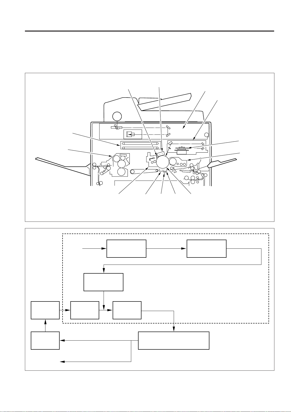
OUTLINE AND COMPOSITION
In this digital copying machine, optical data (light beam) reflected from the original is converted into electrical signals, subjected to
image processing, then converted back into optical data (light beam) and directed onto the drum.
Figure 1 shows the composition of the machine, and Fig.2 an outline of the digital copying process.
Image processing unit
Fixing unit
Cleaning
unit
PCL
PCL
Charging corona unit
Separation
corona unit
TSL
Fig.1
Transfer
corona unit
Image read unit
Image write unit
Polygon mirror
Developing unit
OPC drum
PCL
Cleaning
Fixing
Original
Charging
Optical data
Image write
Image read
Optical data
Developing
Electrical data
Image processing
Separation ← Transfer corona
(Transfer simultaneous
exposure)
Fig.2
Electrical signal
1 - 1
Page 3

PROCESS
IMAGE READ MECHANISM
Light source (xenon lamp)
Lens1st mirror
CCD image sensor
[1] Outline
A xenon lamp is used as the light source, and the light from the
lamp is directed onto the original.
The light reflected off the original is reflected by the 1st, 2nd and
3rd mirrors shown in Fig.1, then passed through the lens and
directed onto the CCD image sensor.
The CCD image sensor consists of 5000 pixels. One pixel is
7 µm in length, and the length on the original that can be read
by one pixel is 63.5 µm.
2nd mirror
3rd mirror
Fig.3
1 - 2
Page 4
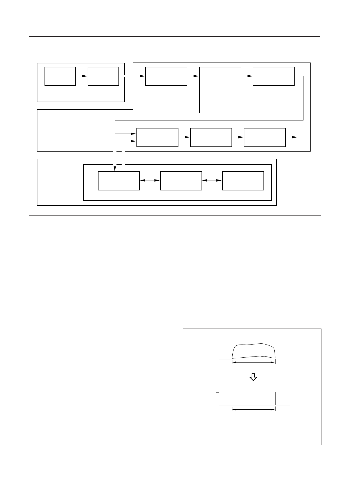
IMAGE PROCESSING
PROCESS
CCD image
sensor
A/D Board
Image Processing Board
Electronic RDH
Processing Board
A/D
conversion
Error diffusion
processing
Shading correction
Selector/SGU
[1] Outline
The analog signal produced by opto-electric conversion by the
CCD image sensor on the A/D board is subjected to analog
processing, then A/D-converted, and transmitted to image
processing board.
Image processing consists of shading correction, brightness/
density conversion, EE processing, text/dot pattern judgement, filter/magnification change processing, copy γ correction, write density control, and 2-beam control. In addition,
Error diffusion processing and image compression are carried out within Electronic RDH.
[2] Analog Processing
In the analog processing board, the minute image signals from
the CCD image sensor are amplified and also level-shifted into
the A/D conversion range.
Amplification and level-shifting take place automatically at the
shading correction timing by an electronic variable resistor,
hence there is no need to perform manual adjustment.
[3] A/D Conversion
The image signals from the analog processing board are
converted one pixel at a time into 9-bit digital signals.
[4] Shading Correction
Shading correction is done to even out the light distribution of
the CCD image sensor. The following correction takes place
at the specified timing.
Brightness/density
conversion,
EE processing, Text/
dot pattern
judgement, Filter/
magnification
processing
Reversal processing
Write density
Image
compression
Fig.4
1. White correction
The voltage output from each pixel of the CCD image
sensor when the white reference plate is exposed to the
light from the exposure lamp is memorized as the maximum output value for that pixel.
2. Black correction
The output voltage from each pixel of the CCD image
sensor when the exposure lamp is out is memorized as the
minimum output voltage for that pixel.
* Based on the difference between the white and black
data for each pixel memorized in 1 and 2 above, the
calculated result that indicates the number of the step
corresponding to the image data read from the original is
output to an accuracy of 10 bits.
(1)
(2)
(1)····Output before shading correction
(2)····Output after shading correction
control
512
0
1024
0
Copy γ correction
2-beam control
Memory
Before shading correction
Read width
After shading correction
Read width
Fig.5
White
Black
White
Black
1 - 3
Page 5

PROCESS
[5] Brightness/Density Conversion
The signal resulting from shading correction corresponds to
the light reflected off the original, hence it is generally called a
brightness signal. The brightness/density conversion section
converts the brightness signal into a 8 bit density data, as
shown below.
255
Density
0
Brightness
Fig.6
1024
[7] Text/Dot Pattern Judgement
In order to copy an original under the optimum conditions, the
text/dot pattern judgement section judges whether the read
part is text, dot pattern or a photograph, and uses the results in
the subsequent filtering section.
[8] Filtering
Appropriate filtering takes place according to the kind of original
and the selected magnification.
(1) Text filter................ Highlights the light and dark parts
of the original.
(2) Dot pattern filter ..... Reduces moire.
(3) Photograph filter .... Improves the gray scale repro-
duction.
[6] EE Processing
A density that is suitable for the density of the original is
automatically selected by EE processing, and a suitable copy
made.
1 - 4
Page 6

PROCESS
[9] Magnification Processing
In an analog copying machine, the horizontal magnification is
changed by changing the scanning speed of the exposure unit,
and the vertical magnification by changing the position of the
lens. In this machine, the horizontal magnification is changed
by changing the scanning speed of the exposure unit, and the
vertical magnification by means of electrical image processing.
The read unit of the CCD (63.5 µm) and the write unit of the
laser (63.5 µm) are equal to each other, and remain unchanged
when the copy image is enlarged or reduced in the vertical
direction. As a result, write data that corresponds exactly to the
write position when the image is enlarged or reduced in the
vertical direction sometimes fails to exist.
1. Vertical magnification change processing
during enlargement
As shown in the example of Fig.10, if the pixel data obtained
when the original is read by the CCD is D
positions of the read data when the image is enlarged are
E
1 to E5. However, the following problems will occur if the
write data consists of this read data alone.
(a) There will be a gap between one data and the next,
resulting in gaps in the image.
(b) The data position and write position will not coincide
exactly.
Consequently, if read data that corresponds exactly to the
write position fails to exist, as indicated by the dotted lines
of Fig.10, the write density is determined as shown below.
Original read position
Data position when
image is enlarged
D1 D2 D3 D4 D5
E1 E2 E4 E5
E3
1 to D5, the
2. Vertical magnification change processing
during reduction
As shown in the example of Fig.11, if the pixel data obtained
when the original is read by the CCD is D1 to D5, the
positions of the read data when the image is reduced
overlap each other as indicated by R1 to R5, hence the
write positions fail to coincide with the write
positions.Therefore, the write density is determined as
shown below.
Original read position
Data position when
image is reduced
Write position
D1 D2 D3 D4 D5
R1 R2 R4 R5
W1 W2 W3 W4 W5
Fig.11
R3
3. Density correction
Figure 12 is a graph the vertical axis of which represents
density (256 steps) and the horizontal axis of which represents position: Here, the distance between E
Fig.10 is set out on the horizontal axis and divided into 16
steps. If the position with respect to write data W
the density S can be obtained using the following equation.
S = E1 + ( ) x
E2 – E1
16
2 and E1 of
2 is “ ”,
Write position
W1 W2 W3 W4 W5 W6 W7 W8
Fig.10
1 - 5
255
S
Density
E1
0
0
Position
Fig.12
E2
W2
15
Page 7

PROCESS
[10] Reversal Processing
This function reverses the input brightness data in order to
reverse black and white when the reverse copy mode is
selected.
[11] Copy γ Correction
The copy γ correction function selects the density curve
corresponding to the density selected by the density button
on the operation panel.
Suitable density curves are provided for the text, photo and text
photo modes.
[12] Selector, SGU
Selector is a function that switches between the image signal
from the Electronic RDH, and the read time image processed
signal.
SGU is a function that generates various test patterns.
[13] Write Density Control
The write density control function converts image data to the
optimum laser exposure based on the characteristics related to
the drum such as drum potential, toner density, etc.
[15] Image Compression Processing
This processing function stores compressed image data in
the memory to enable a large quantity of image data to be
stored when Electronic RDH is used.
[16] Memory
The memory can hold about 180 pages of A4 sized originals
consisting of average word processor text. The number of
pages will be less than this, if the originals include many
photographs and dot pattern images. Expansion memory
units MU-103 are available as an option.
[17] 2-beam Control
This function is used to adjust the timing of the laser data from
the two beams and also to detect and correct any deviation
between the two beams.
1.5
Copy density
0
Laser exposure level
Fig.13
255
[14] Error Diffusion Processing
Error diffusion processing is intended to make efficient use of
the installed memory and also to obtain a satisfactory copy
image.
1 - 6
Page 8

IMAGE WRITE
PROCESS
CY2 lens
Polygon mirror
3rd mirror
Stepping motor
Compression prism 1
Collimator lens unit 1
Semiconductor laser LD1
Glass cover
Index mirror
3rd mirror
Index senser
Fine adjustment
prism 1
Fig.14
fθ lens unit
1st mirror
2nd mirror
CY1 lens
Beam combining prism
Compression prism 2
Collimator lens unit 2
Semiconductor laser LD2
2nd mirror
1st mirror
[1] Outline
Figure 14 shows the layout of the various parts of the write unit.
The processed image data is output by semiconductor lasers.
The light output from these lasers is sent via the path shown in
Fig.15 to the OPC drum.
Semiconductor laser 1
(LD1)
Collimator lens unit 1
Compression prism 1
Fine adjustment prism
1 (sub scanning)
Beam combining
Cylindrical lens 1 (cy1)
fθ lens
unit
3rd mirror
Index mirror
1st mirror
2nd mirror
OPC drum
Semiconductor laser 2
(LD2)
Collimator lens unit 2
Compression prism 2
prism
Polygon mirror
Cylindrical lens 2
(Cy2)
Index sensor
1 - 7
Fig.15
Page 9

PROCESS
[2] Collimator lens
Figure 16 shows the function of the collimator lens. This lens
is used to form the light which diverges from a point source into
a parallel beam.
Semiconductor
laser
Collimator
lens
Fig.16
Parallel
beam
[3] Beam combining prism
This prism causes the beams from the two semiconductor
lasers mounted at right angles to each other to be output in the
same direction.
[6] Polygon mirror
This is a multi-sided mirror which converts the laser beam into
a scanning beam. An octagonal mirror is used in this machine.
Figure 18 shows the appearance of the polygon mirror.
Fig.18
[7] fθ lens
The polygon mirror rotates at a constant angular speed.
Consequently, if a general image forming lens were to be used,
the speed at which the laser beam scans the surface of the
drum would vary at the center and at the both edges of the
drum, as shown in Fig.19.
Laser beam
Semiconductor laser 1
Beam combining prism
Semiconductor laser 2
Fig.17
[4] Compression Prism
This prism shapes the beam radiated from each semiconductor laser, and adjusts the height in the up-down direction.
[5] Fine Adjustment Prism
This prism performs fine adjustment of the beam radiated from
each semiconductor laser in the left-right and up-down directions.
Drum;
Scanning
speed falls as
beam
approaches
center of
Polygon
mirror
Image forming lens
Fig.19
drum.
An fθ lens is used to maintain the scanning speed constant
over the entire length of the drum.
Laser beam
Drum;
Scanning
speed is
constant.
Polygon
mirror
fθ lens
Cylindrical
lens
Fig.20
1 - 8
Page 10

[8] Cylindrical Lenses
Two lenses, cylindrical lens 1 (Cy1) and cylindrical lens 2
(Cy2), are used to eliminate the tilt error of the polygon mirror.
Cylindrical lenses 1 and 2 are installed before and after the
polygon mirror, as shown in Fig.21. The laser beam is focused
on the polygon mirror by means of cylindrical lens 1, and the
light reflected off the polygon mirror is once again focused on
the drum by means of cylindrical lens 2.
The optical relationship between the polygon mirror and the
drum face with respect to cylindrical lens 2 is that of image and
object. Consequently, even if the polygon mirror is tilted, the
light path is corrected by cylindrical lens 2, ensuring that the
beam is scanned along the same line.
PROCESS
Semiconductor
laser
Collimator lens
Cylindrical lens
1 (Cy1)
Polygon
mirror
Fig.21
fθ lens
Cylindrical lens
2 (Cy2)
Mirror
Drum
[9] Index Sensor
This sensor is intended to determine the leading edge write
position for each scan in the axial direction of the drum, and
also to determine the positions of the two beams.
1 - 9
Page 11

PROCESS
IMAGE FORMATION
[1] Charging
Charging corona unit
Fig.22
A negative charging method using a Scorotron is employed. A
constant negative voltage is applied to the charging plate and
back plate in order to maintain the potential of the drum
constant.
[3] Developing
Fig.24
Negatively charged toner adheres to the parts of the surface
of the drum where charge was erased during the exposure
process.
[2] Exposure
Fig.23
Exposure is performed by means of the laser beams, causing
the charge on the drum to be erased. Two laser beams are
used to write (exposure) two lines of image data at a time.
[4]
Transfer/Transfer Synchronization Exposure
Drum
Transfer
corona unit
TSL
Fig.25
The transfer corona unit causes the toner on the drum to be
transferred to the paper by means of a discharge from the back
of the paper.
The TSL improves the transfer of the toner and the separation
of the paper.
1 - 10
Page 12

PROCESS
[5] Separation
Separation corona unit
Fig.26
The separation corona unit erases the charge on the paper by
applying an AC discharge from the back of the paper, thus
enabling the paper to separate from the drum under its own
weight.
[7] PCL
PCL
Drum
Fig.28
The PCL erases the potential remaining on the surface of the
drum.
[6] Cleaning
Cleaning blade
Toner collecting roller
Drum
Fig.27
Toner remaining on the drum is removed by the cleaning blade.
1 - 11
 Loading...