

Page 1

FS-108
FS-108BM
SERVICE HANDBOOK
Sep.1999
Ver.1.0
KONICA CORPORATION
TECHNOLOGY SUPPORT CENTER
TOKYO JAPAN
Page 2

CONTENTS
CONTENTS
SAFETY AND IMPORTANT WARNING ITEMS
Refer to the 7065 service handbook on page C-1
1. FS-108/FS-108BM
FS-108/FS-108BM PRODUCT SPECIFICATIONS
CENTER CROSS-SECTION.................................1-3
DRIVE SYSTEM DIAGRAM ..................................1-4
[1] Paper Conveyance Drive ........................1-4
[2] Stacker Drive...........................................1-5
[3] Folding Drive (FS-108BM only) ..............1-5
PAPER CONVEYANCE PATH ............................... 1-6
[1] Paper Conveyance Path .........................1-6
[2] Non-Sort Mode ........................................1-7
[3] Sort,Group Mode.....................................1-8
[4] Sub-tray Mode.........................................1-9
[5] Staple Mode ..........................................1-10
[6] Booklet Mode (FS-108BM only)............1-12
EXTERNAL SECTION.........................................1-13
[1] Composition(FS-108/FS-108BM) .........1-13
[2] Disassembly and Reassembly.............1-13
CONVEYANCE SECTION...................................1-18
[1] Composition ..........................................1-18
[2] Mechanisms ..........................................1-19
[3] Disassembly and Reassembly..............1-22
[4] M1 (FNS Conveyance) Control.............1-28
[5] Gate Control ..........................................1-30
[6] M13 (Stacker Entrance) Control ...........1-33
M5 (Alignment Plate/Upper ) Control.....
[7]
[8] M15 (Alignment Plate/Lower)
(FS-108BM only)
[9] M2 (Roller Shift)
[10] M7 (Paper Exit Roller)
[11] SD4 (Paper Exit Opening)
[12] M8 (Paper Exit Opening)
STAPLER UNIT ...................................................1-44
[1] Composition .......................................... 1-44
[2] Mechanism ............................................1-45
[3] Disassembly and Reassembly..............1-49
[4] Stapler Control ......................................1-52
MAIN TRA Y SECTION ........................................1-55
[1] Composition ..........................................1-55
[2] Mechanism ............................................1-55
[3] Disassembly and Reassembly..............1-55
[4] Main-Tray Up/Down Control ................. 1-58
FOLDING UNIT (FS-108BM ONLY)....................1-60
[1] Composition ..........................................1-60
[2] Mechanism ............................................1-61
....................................
Control........................
Control
Control ..............
Control .......
Control..........
................
1-1
1-35
1-36
1-38
1-39
1-41
1-43
[3] Disassembly and Reassembly..............1-62
[4] Folding-Unit Control ..............................1-64
FS-108/FS-108BM ADJUSTMENTS...................1-66
[1] Adjusting the Magnets on Conveyance
Guide Plate B ........................................1-66
[2] Adjusting the Magnets on Conveyance
Guide Plate C ........................................1-67
[3] Adjusting the Sub-tray Paper Exit Guide.1-68
[4] Adjusting the Paper-Path Switching
Guide .....................................................1-69
[5] Adjusting the By-pass Guide ................1-70
[6] Adjusting the Shift Position ...................1-72
[7] Adjusting Opening/Closing at
the Paper Exit........................................1-73
[8] Adjusting the Paper Exit-Opening
Solenoid ................................................1-74
[9] Adjusting the Paper Exit-Opening Lower
Guide Plate............................................1-75
[10] Adjusting the Tension Of the Stacker
Paper exit Belt.......................................1-76
[11] Adjusting the Mount Location Of the
Upper Alignment Plates ........................1-76
[12] Adjusting the Tension of the Upper Align-
ment-Plates Drive Timing Belt ..............1-77
[13] Adjusting the Mount Location of the Lower
Alignment Plates(FS-108BM only)........ 1-78
[14] Adjusting the Tension of the Lower-
ALignment-Plate Drive Timing Belt.......1-79
[15] Adjusting the Stapling Position
(Flat Stapling)........................................1-79
[16] Adjusting the Stapler Vertical Positioning . 1-80
[17] Adjusting the Staple Orientation(Stapling-
and-Folding)(FS-108BM only) ..............1-82
[18] Adjusting the Staple Position(Stapling-and-
Folding)(FS-108BM only)......................1-83
[19] Adjusting the Angle Of The Folding
Stopper(FS-108BM only) ......................1-84
[20] Adjusting the Folding-Stopper Positions
(FS-108BM only) ...................................1-85
[21] Adjusting the Tension of the Stapler-
Movement Timing Belt ..........................1-86
[22] Adjusting the Tension of the Stapler-Rotaion
Timing Belt.............................................1-86
[23] Adjusting the Folding Force
(FS-108BM only) ...................................1-87
This section covers the structure,functions,operation and method of disassembling and assembling the machine.
Observe the following precautions when performing disassembly and assembly work.
1. Be sure to unplug the power cord before working on the machine.
2. Perform all reassembly work by reversing the order in which the component was disassembled,unless otherwise specified.
3. Do not lose small parts (screws,etc.) or insert them in the wrong place.
4. Install all parts completely before operating the machine.
5. Do not loosen the screws indicated as disallowed for removal.
Page 3

CONTENTS
2. DIAGRAM
FS-108/FS-108BM ELECTRICAL PARTS LAYOUT
DRAWING....................................................................... 2-1
FS-108/FS-108BM CONNECTOR LA YOUT DRAWING ......2-4
FS-108/FS-108BM OVERALL WIRING DIAGRAM (1/3) ....... 2-7
FS-108/FS-108BM OVERALL WIRING DIAGRAM (2/3) ....... 2-8
FS-108/FS-108BM OVERALL WIRING DIAGRAM (3/3) ....... 2-9
FS-108/FS-108BM CONTROL-BOARD CIRCUIT
DIAGRAM (1/9).................................................... 2-10
FS-108/FS-108BM CONTROL-BOARD CIRCUIT
DIAGRAM (2/9).....................................................
FS-108/FS-108BM CONTROL-BOARD CIRCUIT
DIAGRAM (3/9).................................................... 2-12
FS-108/FS-108BM CONTROL-BOARD CIRCUIT
DIAGRAM (4/9).................................................... 2-13
FS-108/FS-108BM CONTROL-BOARD CIRCUIT
DIAGRAM (5/9).................................................... 2-14
FS-108/FS-108BM CONTROL-BOARD CIRCUIT
DIAGRAM (6/9).................................................... 2-15
FS-108/FS-108BM CONTROL-BOARD CIRCUIT
DIAGRAM (7/9).................................................... 2-16
FS-108/FS-108BM CONTROL-BOARD CIRCUIT
DIAGRAM (8/9).................................................... 2-17
FS-108/FS-108BM CONTROL-BOARD CIRCUIT
DIAGRAM (9
FS-108/FS-108BM CONNECTOR-BOARD CIRCUIT
DIAGRAM ............................................................2-19
FS-108/FS-108BM TIMING CHART (SORT MODE,
A4, 2-PAGE ORIGINAL, 5 COPIES, 1:1 RATIO) ......2-20
FS-108/FS-108BM TIMING CHART (2-STAPLE
MODE, A4, 2-PAGE ORIGINAL, 3 COPIES,
1:1 RATIO) ........................................................... 2-21
FS-108/FS-108BM TIMING CHART (STAPLING
AND FOLDING, A4R, 3-PAGE ORIGINAL, 2
COPIES, 1:1 RATIO, 1-1 MODE)........................ 2-22
/9)............................................................ 2-18
2-11
Page 4

1
FS-108BM FS-108BM
Page 5

FS-108/FS-108BM
Amount of Curll
Copy paper (5 sheets)
Fold height
Original Pages
A3R, 11x17R
0 to 5
11 to 16
6 to 10
25mm or less
Not specified*
50mm or less
A4R, 8.5x11R
25mm or less
Not specified*
B4, 8.5x14R
25mm or less
50mm or less
Not specified*
Not specified*
FS-108/FS-108BM PRODUCT SPECIFICATIONS
1. Type
FS-108: Finishing device implementing offset colla-
tion, stapling, and sub-tray eject
FS-108BM: Finishing device implementing offset colla-
tion, stapling, sub-tray eject, stapling-andfolding, and folding
2. Functions
Type of Paper: Same as for the main body.
Paper Size: A3R, B4R, F4R, A4R, A4, B5R, B5, A5R,
B6R.
B6R is not possible in off-set mode;
B5R, A5R, B6R are not possible in staple
mode. F4R, A4, B5R, B5, A5R, A5, B6R
are not available in booklet mode.
Paper Stacking Capacity:
Sub-tray exit mode:
Maximum 200 sheets (same-size sheets
only)
Non-Staple, Group, and Offset modes:
Maximum 1500 sheets (A3R, B4R, F4R)
Maximum 3000 sheets (B5R, B5, A4R, A4)
Maximum 500 sheets (B6R, A5R, A5)
Staple Mode: Maximum 1000 sheets
Main-Tray Capacity (same-size sheets only)
Original Pages
2 to 9
10 to 20
21 to 30
31 to 40
41 to 50
Other than A3R, 11x17R
100 stacks
50 stacks
30 stacks
25 stacks
20 stacks
A3R, 11x17R
50 stacks
50 stacks
30 stacks
25 stacks
20 stacks
Paper curling: Maximum 10mm
Booklet-mode folding level (FS-108BM only)
(For 80g/m
2
paper or equivalent, same-size sheets only)
* May be unf olded after e xit, pro vided that fold state can
be easily restored.
Amount of sort
off-setting: 30mm (when off-setting/grouping)
Tray: Main tray
Sub-tray
Booklet tray (FS-108BM only)
Booklet Mode (FS-108BM only):
• Stapling-and-folding + folding
20 booklets of 5 folded sheets each (20 pages/booklet; eq. to 400 pages)
• Folding
33 booklets of 3 folded sheets each (12 pages/booklet; eq. to 396 pages)
1-1
Page 6

FS-108/FS-108BM
3. Staple Mode
Number of pages
which may be stapled:
50 sheets maximum* (80g/m
quality paper, 5mm and below)
* Maximum sheets can be set to 45, 40, or 35 in accor-
dance with paper quality and thickness.
Staple position: A = 8.5mm±3mm
(adjustment possible)
B = 8.5mm±3mm
C = 82.5mm±3mm
D = 8.5mm±3mm
(adjustment possible)
E = 14mm±3mm)
2
high-
6. Machine Data
Power Source:
24 VDC, 5 VDC (supplied from the
main body)
Maximum Power
Consumption: 100VA
Weight:
FS-108: Approximately 55kg
FS-108BM: Approximately 80kg
External Dimensions:
85
367
781656
1151
1095
Single staple (rear) Two staples Single staple
Booklet mode (stapling and folding)
(FS-108BM only)
@@@(front)
Staple capacity: 5000 staples/cartridge
4. Booklet Mode (FS-108BM only)
Stapling-and-folding:
Maximum 16 sheets (80g/m2 high-quality paper)
Maximum 15 sheets (80g/m
+ 1 sheet (200g/m
2
high-quality paper)
Folding: Maximum 3 sheets (80g/m2 high-quality paper)
2
high-quality paper)
7. Maintenance
Maintenance: Same as the main body.
Service Life: Same as main body.
8. Machine Operating Environment
Temperature: 10 to 30˚C
Humidity: 10 to 80% RH
These specifications are subject to change without notice.
5. Option
PI-108 (Sheet feeder)
1-2
Page 7

CENTER CROSS-SECTION
Sub-tray
Shift Unit
Main Tray Paper Exit Unit
FS-108/FS-108BM
Gate
Sub-tray Gate
Stacker Unit
Booklet T ra y
Folding Stopper
By-pass Gate
Flat-Stapling Stopper
Stapler Unit
Area within dotted lines:
FS-108BM only
Stapling and
Folding Stopper
Folding Unit
1-3
Page 8

FS-108/FS-108BM
DRIVE SYSTEM DIAGRAM
[1] Paper Conveyance Drive
Sub-tray Paper Exit Roller B
Conveyance Slide Shaft
Sub-tray Paper Exit Roller C
Sub-tray Paper Exit Roller A
Nip Paper Exit Roller
Conveyance Roller D
Conveyance Roller C
Conveyance Roller B
Conveyance Roller A
M1 (FNS Conveyance)
Paper Exit Roller
M7 (Paper Exit
Roller)
Intermediate Conveyance Roller
1-4
Page 9

[2] Stacker Drive
FS-108/FS-108BM
Paper Exit Roller
Paper Exit Belts
Stacker Entrance Roller
Swivel Roller
Paper Exit Arms
[3] Folding Drive (FS-108BM only)
M7 (Paper Exit Roller)
Pulley
M13 (Stacker Entrance)
Folding Roller B
Folding Roller A
Folding Conveyance Roller
Folding Knife
M19 (Folding Knife)
Pressure Roller A
Pressure Roller B
Folding Conveyance Belts
M20 (Folding Conveyance)
1-5
Page 10

FS-108/FS-108BM
PAPER CONVEYANCE PATH
[1] Paper Conveyance Path
The FNS (finisher) provides four paper paths, as shown in the diagram below.
Face-up and face-down inversion is handled by at the main-body side by the main body’s exit page inverter.
Sub-tray
Main T ra y
Booklet T ra y
Finishing
Sort, Group, Non-sort mode
Sub-tray mode
Staple mode
Booklet mode (FS-108BM only)
Paper Conveyance Paths
1-6
Page 11

[2] Non-Sort Mode
Exit to main tray
A paper exited from the main body is conveyed and exited to the main tray.
FS-108/FS-108BM
Sub-tray Gate
Gate
Main T ra y
Paper Exit Roller
Conveyance Roller B
Conveyance Roller A
Conveyance Roller D
Conveyance Roller C
1-7
Page 12

FS-108/FS-108BM
[3] Sort, Group Mode
Exit to the main tray
Paper exited from the main body is conveyed and exited to the main tray. This mode has an off-set function that allows each
page of the even-numbered sets to be exited with the paper shifted 30mm to the rear.
Off-set Function
(1) The odd-numbered pages are exited to the main tray with the image side face down.
(2) The even-numbered pages are shifted 30mm to the rear by the conveyance slide shaft of the shift unit and
then exited to the main tray.
Main T ra y
Paper Exit Roller
Shift Unit
Conveyance Slide Shaft
Conveyance Roller D
Gate
Sub-tray Gate
Conveyance Roller B
Conveyance Roller A
Conveyance Roller C
1-8
Page 13

[4] Sub-tray Mode
The sub-tray gate opens. Paper exited from the main body is conveyed and exited to the sub-tray.
Sub-tray Paper Exit Roller C
Sub-tray
Sub-tray Paper Exit Roller B
Sub-tray Paper Exit Roller A
FS-108/FS-108BM
Sub-tray Gate
Conveyance Roller B
Conveyance Roller A
1-9
Page 14

FS-108/FS-108BM
[5] Staple Mode
(1) The gate switches to the staple mode.
(2) For A4R paper and above, the paper exit opening opens.
(3) The first set of paper is conveyed and stacked.
1) The stacker section roller sends the paper to the flat-stapling stopper and the paper is lined up in the
lengthwise direction.
2) The upper alignment plate lines up paper in the widthwise direction.
3) Paper is stapled.
4) The first set is conveyed by the paper exit arm and exited to the main tray.
Paper Exit Opening
Conveyance Roller C
Main Tray
First Stapled Set
Paper Exit Belt
Stapler Unit
Intermediate Conveyance
Roller
Alignment Plate
/Upper
Gate
Sub-tray Gate
Conveyance Roller B
Conveyance Roller A
By-pass
Gate
Stacker Entrance
Roller
Swivel Roller
Flat-Stapling Stopper
Paper Exit Arm
1-10
Page 15

FS-108/FS-108BM
(4) The second and subsequent sets of paper are conveyed and stacked.
1) The first page stops in the stack er entrance with the by-pass gate opened. The stack er entrance roller stops
to wait for the previous stack to be exited.
2) The by-pass gate is closed and the second page is stacked on top of the first.
3) Once the previous stack has exited, the stack entrance roller rotates and the first and second pages are
simultaneously sent to the stacker.
* The above steps (1) to (3) are for paper to a maximum of A4 size.
4) The stacker section roller sends the paper to the flat-stapling stopper and the paper is lined up in the
lengthwise direction.
5) The upper alignment plate lines up paper in the widthwise direction.
6) When all paper is conveyed to the stacker, the paper is stapled.
7) The second and subsequent sets are conveyed by the paper exit arm and the paper is exited to the main
tray.
Paper Exit Opening
Conveyance Roller C
Second Stapled Set
Main Tray
Intermediate
Conveyance Roller
Paper Exit Belt
Stapler Unit
Alignment Plate/Upper
Second Sheet
Sub-tray Gate
Gate
Conveyance Roller B
Conveyance Roller A
By-pass
Gate
First Sheet
Stacker Entrance Roller
Swivel Roller
Flat-Stapling Stopper
Paper Exit Arm
1-11
Page 16

FS-108/FS-108BM
[6] Booklet Mode (FS-108BM only)
(1) The gate switches to the staple mode.
(2) The paper exit opening opens.
(3) The paper is conveyed and stacked.
(4) The stacker section roller sends the paper to the stapling-and-folding stopper and the paper is lined up in the
lengthwise direction.
(5) The upper and lower alignment plate lines up paper in the widthwise direction.
(6) If stapling-and-folding has been selected, staple the stack.
(7) Release the stapling-and-folding stopper and convey the stack to the folding unit by the paper exit belt.
(8) Convey the stack up to the folding stopper, fold it with the folding knife, and eject to the booklet tray.
Conveyance Roller C
Booklet Tray
Intermediate Conveyance Roller
Paper Exit Belt
Stapler Unit
Upper
Alignment Plate
Pressure Roller A
Folding Roller A
Gate
Sub-tray Gate
Conveyance Roller B
Conveyance Roller A
Stacker Entrance Roller
Swivel Roller
Alignment Plate/Lower
Stapling and Folding stopper
Folding Conveyance Roller
Pressure
Roller B
Folding Stopper
Folding Conveyance Belt
Folding
Roller B
Folding Knife
1-12
Page 17

EXTERNAL SECTION
Screws
Hinge
Front Cover
[1] Composition (FS-108/FS-108BM)
FS-108/FS-108BM
Paper Exit Cover
Sub-tray
Main T ra y
Rear Cover
Paper Exit Stopper Plate
Booklet T ra y
[2] Disassembly and Reassembly
CAUTION: Be sure that the power cord has been un-
plugged from the outlet.
1. Removing and Reinstalling the Rear Cover
a. Procedure
(1) Remove the 5 set screws holding the rear cover
in place, and take off the cover.
Top Cover
Front Cover
Front Side Cover
2. Removing and Reinstalling the Front Cover
a. Procedure
(1) Open the front cover.
(2) Remove the 2 set screws holding the bottom
hinge in place, and take off the front cover.
Screws
Screws
Rear Cover
(2) Reinstall the rear cover in the opposite sequence
to removal.
(3) Reinstall the front cover in the opposite sequence
to removal.
1-13
Page 18

FS-108/FS-108BM
Screw
Paper Exit Cover
Screw
3. Removing and Reinstalling the Top Cover
a. Procedure
(1) Remove the sub-tray.
(2) Open the paper exit cover.
(3) Remove the two caps.
(4) Open the front cover.
(5) Remove the 6 set screws holding the top cover
in place, and take off the cover.
Screws
Cap
4 Removing and Reinstalling the Paper Exit Co ver
a. Procedure
(1) Remove the top cover.
(2) Remove the 2 set screws holding the paper exit
cover in place, and tak e off the paper e xit cover.
Screws
(3) Reinstall the paper cover in the opposite se-
quence to removal.
(6) Reinstall the top cover in the opposite sequence
to removal.
1-14
Page 19

FS-108/FS-108BM
Front Side
Cover
Screws
5. Removing and Reinstalling the Main Tray
a. Procedure
(1) Remove the rear cover.
(2) Detach the connector and remove the 2 set
screws holding motor M3 (tray up-down motor)
in place. Remove M3.
CAUTION: Support the main tray with your hand when
removing M3.
M3 (Tray Up-Down)
Screws
Connector
(3) Remove the 2 set screws holding the main tray
in place, and lift the main tray up and off.
Screws
6. Removing and Reattaching the Front Side Cover
a. Procedure
(1) Remove the 2 set screws holding the front side
cover in place, and take off the front side co ver.
(2) Reinstall the front side cover in the opposite se-
quence to removal.
Main Tray
(4) Reinstall the main tray in the opposite sequence
to removal.
1-15
Page 20

FS-108/FS-108BM
Screws
Screws
Up-Down Stay
Wire Bracket
Wire Bracket
Screws
Screws
Screws
Rear Auxiliary
Side-Up-Down
Plate
Front Auxiliary
Side-Up-Down
Plate
7. Removing and Reinstalling the Paper Exit
Stopper Plate
a. Procedure
(1) Remove the following parts.
• Rear cover
• Main tray
• Booklet tray
• Front cover
• Front side cover
(2) Remove the 4 set screws holding the left and
right up-down covers in place, and remove these
two covers.
Screws
Screws
(3) Remove the 4 set screws from the front and rear
wire brackets (two screws at each bracket), and
then remove the up-down stay.
(4) Remove 8 set screws and tak e off the front and
rear auxiliary side-up-down plates.
Up-Down Covers
1-16
Page 21

FS-108/FS-108BM
Press down
Wire Bracket
Wire Bracket
Screws
Screws
Up-Down Stay
(5) Remove the two plates (front and back plates)
at the booklet exit.
Plate
Screw
Plate
(6) Remove 13 more set screws, and take off the
paper exit stopper.
(7) Remove the up-down sta y . (See “Removing and
reattaching the up-down stay”.)
(8) Reinstall the stopper in the opposite sequence
to removal. But note the following caution.
CAUTION: Be sure to press down on the up-down stay
while tightening the 4 screws for the wire
brackets.
Paper Exit
Stopper Plate
Screws
Screws
Screws
Up-Down Stay
Screws
Screws
1-17
Page 22

FS-108/FS-108BM
Conveyance Section
[1] Composition
Sub-tray Paper Exit Roller C
Sub-tray Paper Exit Roller B
FS-108/FS-108BM Rear
Sub-tray Paper Exit Roller A
Conveyance Roller B
Conveyance Roller A
Conveyance Roller C
Intermediate Conveyance Roller
M1 (FNS Conveyance)
Conveyance Slide Shaft
M7 (Paper Exit Roller)
Nip Paper Exit Roller
Paper Exit Roller
(Sponge Roller)
Conveyance Roller D
M13 (Stacker Entrance)
Stacker Entrance Roller
Paper Exit Belt
Area within dotted lines: FM-108BM only
Folding Conveyance Roller
Folding Conveyance Belt
M20 (Folding Conveyance)
Folding Roller A
Pressure Roller A
Pressure Roller B
Folding Roller B
1-18
Page 23

FS-108/FS-108BM
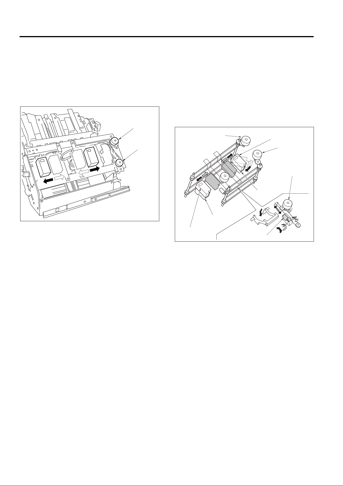
Link Mechanism
M2 (Roller Shift)
M2 (Roller Shift)
Paper exit direction
Slide Shaft
Link Mechanism
Slide Shaft
30mm towards the direction
of the back side
[2] Mechanisms
1. Paper Conveyance
Paper conveyance is carried out by conveyance rollers A,
B, C, and D; the intermediate conveyance roller; the conveyance slide shaft; and sub-tray paper exit rollers A, B,
and C. These components are driven b y M1 (FNS conv eyance) by means of a timing belt.
Stacking is implemented by the stacker entrance roller and
the swivel roller. These rollers are driven by the M13
(stacker entrance) by means of a timing belt.
Ejection to the main tray (following staple processing) is
implemented by the stacker paper exit belt arm and the
paper exit roller. These components are driven by the M7
(paper exit).
Ejection to the booklet tray is implemented by the folding
convey ance roller, the folding conve yance belt, the f olding
knife, f olding rollers A and B, and pressure rollers A and B.
The folding knife is driven by M19 (folding knife). The conveyance belt, folding rollers, and pressure rollers are driven
by the M20 (folding conveyance) by means of a timing
belt.
2. Paper Path Switching
Gate
Sub-tray Gate
SD2
(Sub-tray Paper Exit)
By-pass Gate
SD5 (By-pass)
SD1 (Gate)
Path switching is carried out b y the gate, the sub-tray gate ,
and the by-pass gate. Each of these is controlled by the
ON/OFF action of a corresponding solenoid: SD1 (gate),
SD2 (sub-tray paper exit), and SD5 (b y-pass), respectively .
3. Shift Unit Sort Shift Operation
(1) Paper entering the shift unit is fed toward the
paper exit direction by the action of the slide
shaft.
(2) Driving by M2 (roller shift) causes the linkage to
shift the slide shaft and paper 30mm toward the
rear.
1-19
Page 24

FS-108/FS-108BM
4. Stacker Unit
Alignment Plate/
Upper
Paper Exit
Belts
FS-108BM Only
M17 (Stapling and Folding Stopper Release)
Paper Exit Arms
Alignment Plate/Upper
M14
(Stapling and Folding Stopper)
M5
(Alignment
Plate/Upper)
Paper Alignment (Staple Mode (Flat Stapling))
Sheets conveyed into the stacker are aligned by the oscillation of the (front and rear) alignment plates/upper. The
alignment plates/upper are driven by M5 (alignment plate/
upper).
Paper Alignment (Booklet Mode (FS-108BM only))
Sheets conveyed into the stacker are aligned by the movement of the (front and rear) alignment plates/upper and
the (front and rear) alignment plates/lower . The alignment
plates/upper are driven by M5 (alignment plate/upper); the
alignment plates/lower are driven by M15 (alignment plate/
lower). The stapling-and-folding stopper is moved b y M14
(stapling-and-folding stopper) and is released by M17 (stapling-and-folding stopper release).
Paper Exiting
Stapled paper is sent to the paper exit by the paper exit
arm. The paper exit belt is driven b y M7 ( paper exit-roller).
Feeding to the Folding Unit (FS-108BM only)
M17 (stapling-and-folding stopper release) releases the
stapling-and-folding stopper and feeds the paper into the
folding unit.
Alignment Plate/
Lower
Alignment
Plate/Lower
M15
(Alignment Plate/
Lower)
Stapling and Folding Stopper
1-20
Page 25

FS-108/FS-108BM
Conveyance
Roller B
Conveyance Roller A
Conveyance
Roller C
Conveyance Roller D
Paper Exit Rolle
r
Main T ra y
Paper Exit Opening
SD4 (Paper Exit Opening)
Nip Roller
Paper Exit Roller
SD4 (Paper Exit
Opening)
5. Paper Exit Opening Unit
M8
SD4 (Paper Exit Opening)
Paper Exit Opening
Nip Roller
(Paper Exit Opening)
a. Staple Mode and Booklet Mode Operation for
Paper Sizes A4R and Above
Because paper of this size juts out from the stacker, the
paper exit opening is held open from the start of copying
until the completion of stapling.
c. Pressure of the Paper Exit Roller
The paper exit roller turns more slowly than the conveyance rollers (A, B, C, and D), and remains unengaged by
the nip roller except during ejection.
When paper reaches the paper exit opening, the paper
exit roller is engaged by the nip roller and the paper is
ejected to the main tray. Engagement and release is controlled by SD4 (paper exit opening).
b. Paper Exit of the Staple Mode (Flat Stapling)
Upon completion of stapling, the paperr exit closes, and
the paper is grasped and ejected to the main tray. The
opening and closing of the paper exit is controlled by M8
(paper exit opening).
M8 (Paper Exit Opening)
Paper Exit Opening
Open
Close
1-21
Page 26

FS-108/FS-108BM
Sponge Roller
Match
Match
6. Folding by the Folding Unit (FS-108BM only)
Paper is conveyed to the folding stopper by the action of
the folding conveyance roller and the folding conveyance
belts, and is then folded by the action of the folding knife
and the folding rollers. The folding conveyance roller, the
folding conveyance belts, the folding rollers, and the pressure roller are driven by M20 (folding conveyance). M18
(folding stopper) drives the folding stopper. M19 (folding
knife) drives the folding knife.
M20
(Folding Conveyance)
Folding Rollers
M18
(Folding
Stopper)
Folding Conveyance Belts
[3] Disassembly and Reassembly
CAUTION: Be sure that the power cord has been un-
plugged from the outlet.
1. Replacing a Paper Exit Roller (Sponge Roller)
a. Procedure
(1) Run the copier in mode 47 (code 75-06) to lower
the main tray.
Sponge Roller
Main Tray
Folding
Paper-End Stopper
Paper
Folding Knife
Folding Knife
Folding Knife
M19 (Folding Knife)
(2) Insert the end of a screwdriver into the slot in
the sponge roller, and twist the screwdriver to
pry the roller off.
(3) Take the two halves of the new sponge roller
and align their indentations with the indentations
on the roller shaft.
(4) Press the two halves of the roller together until
the click into place.
1-22
Page 27

FS-108/FS-108BM
Clamps
Wirings
M2 (Roller Shift) Connector
PS18 (Roller Shift HP)
Connector
Clamp Screw
Screws
Ground Wire
Fixing Screw
Shift Unit
Screws
2. Replacing an Intermediate Conveyance
Roller (Sponge Roller)
a. Procedure
(1) Open the front cover and pull out the stacker/
stapler unit.
(2) Insert the end of a screwdriver into the slot in
the sponge roller, and twist the screwdriver to
pry the roller off.
Sponge Rollers
3. Removing and Reinstalling the Shift Unit
a. Procedure
(1) Remove the following parts.
• Rear cover
• Top cover
• PI-108 (if installed)
(2) Detach the M2 (roller shift) and PS18 (roller shift
HP) connectors.
(3) Remove the wiring from the three clamps.
Sponge Roller
(3) Take the two halves of the new sponge roller
and align their indentations with the indentations
on the roller shaft.
(4) Press the two halves of the roller together so
that they click into place.
Match
Match
(4) Remove the ground wire fixing screw.
(5) Remove the clamp set screw.
(6) Remove 4 more set screws (see illustration).
1-23
Page 28

FS-108/FS-108BM
Drive Belt
Pulley
Belt
Collar
E-ring
Gear
E-ring
Collar
Shaft Holder
(7) Remove 3 more set screws and remo ve the shift
pulley .
(8) Slide the conveyance slide shaft and take out
the shift unit.
Screws
Conveyance
Slide Shaft
Screw
Shift Pulley
(9) Reinstall the shift unit in the opposite sequence
to removal.
CAUTION: When reinstalling the shift unit, be sure to
align the conveyance slide shaft with the hole
in the shift pulley.
4. Removing and Reinstalling the Paper Exit-Opening
Unit
a. Procedure
(1) Remove the following parts.
• Rear cover
• Top cover
• Front side cover
• PI-108 (if installed)
• Shift unit
(2) Remove the pulley and its belt.
(3) Remove the E-ring, and then remove the collar,
the gear, and the drive belt.
(4) Remove the collar, E-ring, and shaft holder.
1-24
Page 29

FS-108/FS-108BM
Spring
(5) Remove the clamp set screw and the ground
wire screw.
(6) Detach the SD4 (paper exit opening) and PS6
(paper exit-1) connectors.
(7) Remove the screw holding PS10 (paper exit-2)
to the unit. Remove PS10 and detach the connector.
CAUTION: When withdrawing the PS10, ensure that
needless force is not applied to the lever
below the PS10.
Clamp Screw
SD4 (Paper Exit
Opening) Connector
Ground Wire Screw
PS6 (Paper Exit-1)
Connector
(9) Open the front cover. Remove the front side E-
ring and the shaft holder.
E-ring
Shaft Holder
(10)Remove the spring.
PS10 (Paper Exit-2)
PS10 (Paper Exit-2)
Screw
(8) Remove the paper exit opening open-shut link
screw.
Paper Exit Opening
Open-Shut Link
Screw
1-25
Page 30

FS-108/FS-108BM
Stacker/Stapler Unit
Rail Stopper Screw
Rail Stopper Screw
Screws
Screws
Cover
(11)Remove the 4 set screws holding the paper e xit-
opening cover in place, and take off the cover.
(12)Lift the paper exit-opening unit up and out.
Paper Exit-Opening Cover
Screws
Screws
Paper Exit-Opening Unit
(13)Reinstall the unit in the opposite sequence to
removal.
5. Removing and Reinstalling the Stacker/Stapler
Unit
a. Procedure
(1) Open the front cover and pull the stacker/sta-
pler unit part of the way out..
(2) Remove the 2 rail-stopper set screws . Then pull
the stacker/stapler unit all of the way out.
(3) Remove 4 set screws holding the cov er in place,
and remove the cover.
1-26
Page 31

FS-108/FS-108BM
Cartridge Rails
Screws
Screws
Screws
Screw
Screw
Stacker/
Stapler Unit
(4) Remove the 2 set screws holding the bundle
guide arm to the stacker/stapler unit.
Screws
Bundle Guide Arm
(5) Detach the two connectors from the connector
board at the rear of the stacker/stapler unit.
(6) Remove the 4 set screws holding the cartridge
rails in place, and take out the cartridge rails.
(7) Remove the final 4 set screws holding the
stacker/stapler unit in place. Remove the
stacker/stapler unit.
Connector
Connector
(8) Reinstall the stacker/stapler unit in the opposite
sequence to removal.
1-27
Page 32

FS-108/FS-108BM
Sub-tray
Sub-tray Paper Exit Roller C
PS1 (Sub-tray
Paper Exit)
Sub-tray Paper
Exit Roller A
Sub-tray
Paper Exit Roller B
M1 (FNS
Conveyance)
PS4
(FIN Entrance
Path)
Sub-tray
Conveyance
Roller A
Conveyance Roller B
[4] M1 (FNS Conveyance) Control
24V
24V
PGND
PGND
PS1IN
GND
PS4IN
GND
GND
GND
1-B6
5V
1-B1
1-B2
1-B3
1-B4
1-B5
1-B19
1-B20
1-B13
1-B14
5V
1-A12
1-A30
1-A21
1-A11
5V
1-A29
1-A20
5V
1-A13
5V
1-B18
1-A22
24V-IN
24V
5V
SGND
PGND
PGND
TXD
NC
DTR
NC
CTS
NC
RXD
NC
DSR
NC
RTS
NC
MAIN BODY
MS1
28-6
28-3
28-1
114-1
114-2
114-5
114-3
114-7
114-6
6-1
2-9
2-7
6-3
6-4
6-5
6-6
7-1
7-2
7-3
7-4
7-5
7-6
7-7
7-8
7-9
7-10
7-11
7-12
5V
SGND
PGND
PGND
RXD
SGND
CTS
SGND
DTR
SGND
TXD
SGND
RTS
SGND
DSR
SGND
M1BRK
M1CONT
M1CLK
M1PLL
M1F/R
PS10IN
PS207IN
FNS CB
M1 (finisher convey ance) drives paper conve yance (if maintray exit) and paper exit (if sub-tray exit) by means of conveyance rollers A, B , C , D, convey ance slide shaft and the
sub-tray paper paper exit roller A, B , C . M1 is controlled by
the FNS CB (FNS control board).
M1
PS1
PS4
PS207
1. Operation
a. Interlock
FNS paper-conveyance drive control is initiated by the ON
signal from the main body START button. If MS1 (interlock) is OFF at this time, however, the finisher transmits
an error signal to the main body CB and does not begin
control.
b. PS207 (paper exit cover open/close detection)
control
As mentioned above, FNS paper-conveyance drive control is initiated by the ON signal from the main body ST AR T
button. But if PS207 (paper exit cover open/close detector) is [H] at this time (paper exit cover is open), the FNS
transmits an error signal to the main body CB and does
not begin control.
c. M1 (FNS conveyance) control
(1) Main tray paper exit operation
M1 (FNS conveyance) is set ON by the ON signal of the START button and goes OFF a preset
time interval after PS4 (FIN entrance passage)
detects the trailing edge of the final copy paper.
(2) Sub-tray paper exit operation
M1 is set ON by the START button ON signal,
and begins with rapid rotation. M1 then switches
to slow rotation a preset time period after PS4
detects the trailing edge of the paper. M1 then
returns to rapid rotation to prepare for transport
of the next paper. M1 goes OFF a preset time
period after PS4 detects the trailing edge of the
final paper.
1-28
Page 33

2. Signals
a. Input signals
(1) TXD (Main-Body CB → FNS CB)
Serial data line; transmits operating status of the
main body’s CB to the FNS CB.
(2) DTR (Main-Body CB → FNS CB)
Request to send signal from the main body to
the FNS.
(3) RTS (Main-Body CB → FNS CB)
Transmission acknowledgment signal from the
main body to the FNS.
(4) 24V IN (MS1 → FNS CB)
Outputs +24V if MS1 (interlock) is ON. The
power is supplied to all loads on the FNS side.
(5) PS207 IN (PS207 → FNS CB)
Inputs [L] when the sub-tray paper paper exit
cover is closed.
(6) PS4 IN (PS4 → FNS CB)
Comes ON and inputs [L] when paper passes
through the FNS inlet.
(7) MI PLL (M1 → FNS CB)
Monitors rotation status of M1 (FNS conveyance).
[L] is input when M1 reaches the specified speed.
FS-108/FS-108BM
b. Output signals
(1) TXD (FNS CB → Main-Body CB)
Serial data line; transmits FNS operating status
to the main body’s CB.
(2) RTS (FNS CB → Main-Body CB)
Request to send signal from the FNS to the main
body .
(3) DTR (FNS CB → Main-Body CB)
Transmission acknowledgment signal from the
FNS to the main body.
(4) M1 CONT (FNS CB → M1)
M1 (FNS conveyance) drive control signal.
[H]: OFF
[L]: ON
(5) M1 BRK (FNS CB → M1)
M1 (FNS conveyance) brake signal.
[H]: OFF
[L]: ON
(6) M1 CLK (FNS CB → M1)
Reference clock signal for controlling the speed
of M1 (FNS conveyance).
(7) M1 F/R (FNS CB → M1)
M1 (FNS conveyance) direction signal.
[H]: Counterclockwise
[L]: Clockwise
1-29
Page 34

FS-108/FS-108BM
PS1
(Sub-tray
Paper Exit)
PS4
(FIN Entrance
Passage)
PS5 (Stacker Conveyance Passage)
PS6 (Paper Exit-1)
SD1 (Gate)
SD5
(By-pass)
Stacker Entrance Roller
SD2
(Sub-tray
Paper Exit)
[5] Gate Control
DRV
1-B26
24V
1-B27
DRV
24V
DRV
24V
PS4IN
GND
PS5IN
GND
PS6IN
GND
1-B24
1-B28
1-B23
1-A3
5V
1-A11
1-A29
1-A20
5V
1-A11
1-A28
1-A19
5V
1-A9
1-A27
1-A18
24V-IN
MS1
24V
5V
SGND
PGND
PGND
TXD
NC
DTR
NC
CTS
NC
RXD
NC
DSR
NC
RTS
NC
MAIN BODY
28-6
28-3
28-1
114-1
114-2
114-5
114-3
114-7
114-6
2-9
2-7
6-1
6-3
6-4
6-5
6-6
7-1
7-2
7-3
7-4
7-5
7-6
7-7
7-8
7-9
7-10
7-11
7-12
5V
SGND
PGND
PGND
RXD
SGND
CTS
SGND
DTR
SGND
TXD
SGND
RTS
SGND
DSR
SGND
FNS CB
The paper conveyance path is switched by the ON/OFF
switching of SD1 (gate), SD2 (sub-tray paper exit), and
SD5 (by-pass), which are switched ON/OFF by the FNS
CB (FNS control board).
1. Operation
SD1
SD2
SD5
PS4
PS5
PS6
a. Main-tray Paper Exit Operation (Sort, Group, and
Non-Sort modes)
Paper moves through the shift unit and paper exits to the
main tray, passing through the sub-tray gate and the gate.
As both these gates direct the paper toward the shift-unit
side by default, SD2 (sub-tray paper exit) and SD1 (gate)
remain off.
1-30
Page 35

FS-108/FS-108BM
Finishing
SD1
Sort, Group, and Non-Sort modes
Sub-tray mode
ON
SD5
ON
(OFF)
OFF
SD2
Staple mode, sizes A4,
B5 ( ) is for sizes other
than A4, B5
First paper of
2nd or
subsequent set
Others
Booklet mode (FS-108BM only)
ON
ON
ON
OFF
OFF
OFF
OFF
OFF
OFF
OFF
OFF
OFF
b. Stacker conveyance operation (Staple mode)
Paper moves through the stacker unit to the main tray,
passing the sub-tray gate, the gate, and the by-pass gate.
As the sub-tray gate is already set to the stacker side, SD2
(sub-tray paper paper exit) remains off.
(1) ON timing for SD1 (gate)
SD1 comes on when the START button ON signal is received, setting the gate to the stacker
side. The FNS stands by for paper conveyance
to begin.
(2) Conveyance of paper sizes other than A4 and
B5
The gates direct the paper into the stacker . SD5
remains OFF, as paper moves without by-pass
toward the stacker entrance roller.
(3) Conveyance of A4 and B5 paper (first paper of
second and subsequent sets)
SD5 comes ON a preset time period after PS4
(FIN entrance passage) detects the trailing edge
of the final paper of the preceding set. This
switches the by-pass gate to the by-pass side,
so that the first paper of the new set is carried to
that side.
(4) Conveyance of A4 and B5 paper (second and
subsequent papers of second and subsequent
sets)
SD5 goes OFF a preset time period after PS4
detects the trailing edge of the first sheet of the
current set, closing the by-pass gate. The second sheet moves directly (without by-pass), together with the first paper, to the stac ker entrance
roller.
SD5 remains off for the third and subsequent
sheets of the set, which move without by-pass
to the stacker.
(5) OFF timing for SD1 (gate)
SD1 goes OFF a preset time period after PS6
(paper exit-1) detects the final stapled set.
c. Stacker conveyance operation (Booklet mode)
(FS-108BM only)
Paper moves through the stacker unit to the folding unit,
passing the sub-tray gate, the gate, and the by-pass gate.
As the sub-tray gate is already set to the stacker side, SD2
remains off.
(1) ON timing for SD1 (gate)
SD1 comes on when the START button ON signal is received, setting the gate to the stacker
side. The FNS stands by for paper conveyance
to begin.
(2) The gates direct the paper to the stacker. SD5
remains OFF, as paper moves without by-pass
toward the stacker entrance roller.
(3) OFF timing for SD1 (gate)
SD1 goes OFF a preset time period after PS6
(paper exit-1) detects the final stapled set.
d. Sub-tray paper exit operation
SD2 (sub-tray paper exit) comes on when the START button ON signal is received, setting the sub-tray gate to the
sub-tray side. SD2 goes OFF a preset time period after
PS4 (FIN entrance passage) detects the final sheet.
1-31
Page 36

FS-108/FS-108BM
2. Signals
a. Input signals
(1) TXD (Main-Body CB → FNS CB)
Serial data line; transmits operating status of the
main body’s CB to the FNS CB.
(2) DTR (Main-Body CB → FNS CB)
Request to send signal from the main body to
the FNS.
(3) RTS (Main-Body CB → FNS CB)
Transmission acknowledgment signal from the
main body to the FNS.
(4) PS1 IN (PS1 → FNS CB)
Comes ON ([L]) when paper passage is detected
at the sub-tray paper paper exit.
(5) PS4 IN (PS4 → FNS CB)
Comes ON ([L]) when paper passage is detected
at the FNS entrance.
(6) PS5 IN (PS5 → FNS CB)
Comes ON ([L]) when paper passage is detected
at the stacker entrance.
(7) PS6 IN (PS6 → FNS CB)
Comes ON ([L]) when paper passage is detected
at the main-tray paper paper exit.
b. Output signals
(1) TXD (FNS CB → Main-Body CB)
Serial data line; transmits FNS operating status
to the main body CB.
(2) RTS (FNS CB → Main-Body CB)
Request to send signal from the FNS to the main
body .
(3) DTR (FNS CB → Main-Body CB)
Transmission acknowledgment signal from the
FNS to the main body.
(4) SD1 DRV (FNS CB → SD1)
SD1 (gate) drive control signal.
[H]: OFF
[L]: ON
(5) SD2 DRV (FNS CB → SD2)
SD2 (sub-tray) drive control signal.
[H]: OFF
[L]: ON
(6) SD5 DRV (FNS CB → SD5)
SD5 (by-pass) drive control signal.
[H]: OFF
[L]: ON
1-32
Page 37

[6] M13 (Stacker Entrance) Control
PS4
(FIN Entrance
Passage)
PS5 (Stacker Conveyance Passage)
PS6 (Paper Exit-1)
Stacker Entrance Roller
M13 (Stacker Entrance)
Swivel Roller
Flat-Stapling Stopper
Stapling and
Folding Stopper
FS-108/FS-108BM
24V
24V
24V
24V
21-A1
21-A2
21-A3
21-A4
21-A5
21-A6
25-A11
25-A7
25-A8
25-A9
25-A10
25-A12
M13
M13DRVA
M13DRVA
M13DRVB
M13DRVB
M13DRVA
M13DRVA
M13DRVB
M13DRVB
MS1
28-6
24V
2-9
5V
SGND
PGND
PGND
TXD
DTR
CTS
RXD
DSR
RTS
2-7
28-3
28-1
114-1
NC
114-2
NC
114-5
NC
114-3
NC
114-7
NC
114-6
NC
MAIN BODY
M13 (stacker entrance) drives the stacker entrance roller
and the swivel roller , thereby carrying out the following functions: conveyance of paper to the stacker; paper alignment;
and adjustment of staple waiting time. M13 is controlled
by the FNS CB (FNS control board) via the RB (relay
board).
4-A1
4-A2
4-A3
4-A4
4-A5
4-A6
6-1
6-3
6-4
6-5
6-6
7-1
7-2
7-3
7-4
7-5
7-6
7-7
7-8
7-9
7-10
7-11
7-12
M13DRVA
M13DRVA
M13DRVB
M13DRVB
24V
24V
24V-IN
5V
SGND
PGND
PGND
RXD
SGND
CTS
SGND
DTR
SGND
TXD
SGND
RTS
SGND
DSR
SGND
5V
1-A11
PS4IN
GND
PS5IN
GND
1-A29
1-A20
5V
1-A11
1-A28
1-A19
PS4
PS5
FNS CBRB
1. Operation
Conveyance to the stacker varies according to paper size:
one method is used for A4 and B5, another is used for all
other sizes.
1-33
Page 38

FS-108/FS-108BM
a. Conveyance to the stacker (sizes other than A4
or B5)
(1) M13 ON timing
M13 (stacker entrance) is set ON b y the START
button ON signal, and begins with rapid rotation. M13 then switches to slow rotation a preset time period after PS4 (FIN entrance passage)
detects the trailing edge of the first paper. M13
then returns to rapid rotation a preset period after PS5 (stacker conveyance passage) detects
the trailing edge of the paper. This action is repeated as necessary to transport all papers to
be stacked into the stacker.
(2) M13 OFF timing
M13 goes OFF a preset time period after PS5
(stacker conveyance passage) detects the trailing edge of the final paper set.
b. Conveyance to the stacker (A4 and B5 sizes)
(1) First set
Paper for the first set to be stapled is conveyed
in the same way as other paper sizes.
(2) First paper of second and subsequent sets
M13 goes OFF a preset time period after PS4
(FIN entrance passage) detects the trailing edge
of the first paper for the second or subsequent
set, and the paper moves into the by-pass . This
prevents paper from moving into the stacker
while stapling of the previous set is still in
progress.
(3) Second and subsequent papers of second and
subsequent sets
M13 resumes slow rotation a preset time period
after PS4 detects the trailing edge of the second paper of the set. This causes the first and
second papers to move together (one atop the
other) into the stacker. M13 switches to rapid
rotation a preset time period after PS5 (stacker
conveyance passage) detects the trailing edge
of the first and second papers, so that it is ready
to handle the third paper of the set when it arrives from the main body. Third and subsequent
papers for the set are then conveyed in the same
way as the papers in the first set.
c. Paper alignment (trailing-edge alignment)
For operation in staple mode:
The swivel roller adjusts the position of each paper (one
paper at a time) within the stacker.
For operation in booklet mode (FS-108BM only): The stapling & folding stopper is moved and set into appropriate
position. The swivel roller adjusts the position of each paper (one paper at a time).
2. Signals
a. Input signals
(1) TXD (Main-Body CB → FNS CB)
Serial data line; transmits operating status of the
main body’s CB to the FNS CB.
(2) DTR (Main-Body CB → FNS CB)
Request to send signal from the main body to
the FNS.
(3) RTS (Main-Body CB → FNS CB)
Transmission acknowledgment signal from the
main body to the FNS.
(4) PS4 IN (PS4 → FNS CB)
Comes ON ([L]) when paper passage is detected
at the FNS entrance.
(5) PS5 IN (PS5 → FNS CB)
Comes ON ([L]) when paper passage is detected
at the stacker entrance.
(6) PS6 IN (PS6 → FNS CB)
Comes ON ([L]) when paper is detected at the
main-tray paper paper exit.
b. Output signals
(1) TXD (FNS CB → Main-Body CB)
Serial data line; transmits FNS operating status
to the main body’s CB.
(2) RTS (FNS CB → Main-Body CB)
Request to send signal from the FNS to the main
body .
(3) DTR (FNS CB → Main-Body CB)
Transmission acknowledgment signal from the
FNS to the main body.
(4) M13 DRV A,A / M13 DR V B ,B (FNS CB → RB
→ M13)
M13 (stacker entrance) drive control signals.
1-34
Page 39

[7] M5 (Alignment Plate/Upper) Control
Alignment
Plate/Upper
PS5
(Stacker Conveyance
Passage)
M5 (Alignment Plate/Upper)
FS-108/FS-108BM
M5DRVA
M5DRVA
M5DRVB
M5DRVB
PS 8IN
PS8IN
GND
24V
24V
M5DRVA
M5DRVA
M5DRVB
M5DRVB
21-A15
21-A16
21-A17
21-A18
21-B26
5V
25-A5
25-A3
25-A1
25-B2
25-B1
25-B6
25-B5
25-B4
25-B3
M5
PS8
24V
5V
SGND
PGND
PGND
TXD
NC
DTR
NC
CTS
NC
RXD
NC
DSR
NC
RTS
NC
MAIN BODY
PS5
MS1
28-6
28-3
28-1
114-1
114-2
114-5
114-3
114-7
114-6
2-9
2-7
4-A15
4-A16
4-A17
4-A18
4-B26
1-A10
1-A28
1-A19
6-1
6-3
6-4
6-5
6-6
7-1
7-2
7-3
7-4
7-5
7-6
7-7
7-8
7-9
7-10
7-11
7-12
FNS CBRB
M5DRVA
M5DRVA
M5DRVB
M5DRVB
PS 8IN
M5 (alignment plate/upper) aligns the paper widthwise in
the stacker by opening and closing the alignment plates/
upper. M5 is controlled by the FNS CB (FNS control board)
via the RB (relay board).
1. Operation
At start-up, the alignment plates/upper are stationary at
the ON position of PS8 (alignment-plate/upper HP). A specified time period after PS5 (stacker conveyance passage)
detects the paper trailing edge, M5 begins rotation so as
to close the plates. After another specified interval it opens
the plates. This cycle repeats for each paper.
5V
PS5IN
GND
24V-IN
5V
SGND
PGND
PGND
RXD
SGND
CTS
SGND
DTR
SGND
TXD
SGND
RTS
SGND
DSR
SGND
2. Signals
a. Input signals
(1) TXD (Main-Body CB → FNS CB)
Serial data line; transmits operating status of the
main body’s CB to the FNS CB.
(2) DTR (Main-Body CB → FNS CB)
Request to send signal from the main body to
the FNS.
(3) RTS (Main-Body CB → FNS CB)
Transmission acknowledgment signal from the
main body to the FNS.
(4) PS5 IN (PS5 → FNS CB)
Comes ON ([L]) when paper passage is detected
at the stacker entrance.
(5) PS8 IN (PS8 → RB → FNS CB)
Detects the position of the upper alignment
plates. [L] when the plates are at home position.
b. Output signals
(1) TXD (FNS CB → Main-Body CB)
Serial data line; transmits FNS operating status
to the main body’s CB.
(2) RTS (FNS CB → Main-Body CB)
Request to send signal from the FNS to the main
body .
(3) DTR (FNS CB → Main-Body CB)
Transmission acknowledgment signal from the
FNS to the main body.
(4) M5 DRV A ,A, B,B (FNS CB → RB → M5)
M5 (alignment plate/upper) drive control signals.
1-35
Page 40

FS-108/FS-108BM
Alignment
Plate/Upper
PS5
(Stacker Conveyance
Passage)
Alignment Plate/
Lower
M5 (Alignment Plate/Upper)
M15 (Alignment Plate/Lower)
[8] M15 (Alignment Plate/Lower) Control (FS-108BM only)
PS24
M15
27-3
27-2
27-1
27-4
27-5
27-6
27-7
27-8
27-9
PS24IN
GND
24V
24V
M15DRVA
M15DRVA
M15DRVB
M15DRVB
M15DRVA
M15DRVA
M15DRVB
M15DRVB
PS24IN
22-A5
22-A6
22-A7
22-A8
22-B5
5V
M15 (alignment plate/lower) aligns the stapling-and-folding position by opening and closing the alignment plates/
lower. M15 is controlled by the FNS CB (finisher control
board) via the RB (relay board).
MS1
24V
5V
SGND
PGND
PGND
TXD
NC
DTR
NC
CTS
NC
RXD
NC
DSR
NC
RTS
NC
MAIN BODY
1-A10
PS5IN
GND
5V
1-A28
1-A19
PS5
28-6
28-3
28-1
114-1
114-2
114-5
114-3
114-7
114-6
M15DRVA
5-A5
M15DRVA
5-A6
M15DRVB
5-A7
M15DRVB
5-A8
PS24IN
5-B5
24V-IN
6-1
6-3
2-9
2-7
6-4
6-5
6-6
7-1
7-2
7-3
7-4
7-5
7-6
7-7
7-8
7-9
7-10
7-11
7-12
5V
SGND
PGND
PGND
RXD
SGND
CTS
SGND
DTR
SGND
TXD
SGND
RTS
SGND
DSR
SGND
FNS CBRB
1. Operation
At start-up, the alignment plates/lower are stationary at
the ON position of PS24 (alignment-plate/lower HP). A
specified time period after PS5 (stacker conveyance passage) detects the paper trailing edge, M15 begins rotation
so as to close the plates. After another specified interval it
opens the plates. This cycle repeats for each paper.
1-36
Page 41

2. Signals
a. Input signals
(1) TXD (Main-Body CB → FNS CB)
Serial data line; transmits operating status of the
main body’s CB to the FNS CB.
(2) DTR (Main-Body CB → FNS CB)
Request to send signal from the main body to
the FNS.
(3) RTS (Main-Body CB → FNS CB)
Transmission acknowledgment signal from the
main body to the FNS.
(4) PS5 IN (PS5 → FNS CB)
Comes ON ( [L]) when paper passage is detected at the stacker entrance.
(5) PS24 IN (PS24 → connector board → FNS CB)
Detects the position of the lower alignment
plates. [L] when the plates are at home position.
b. Output signals
(1) TXD (FNS CB → Main-Body CB)
Serial data line; transmits FNS operating status
to the main body’s CB.
(2) RTS (FNS CB → Main-Body CB)
Request to send signal from the FNS to the main
body .
(3) DTR (FNS CB → Main-Body CB)
Transmission acknowledgment signal from the
FNS to the main body.
(4) M15 DRV A,A,B,B (FNS CB → RB → M15)
M15 (alignment plate/lower) drive signals.
FS-108/FS-108BM
1-37
Page 42

FS-108/FS-108BM
PS4
(FIN Entrance
Passage)
PS18 (Roller Shift HP)
M2 (Roller Shift)
Conveyance Slide Shaft
Paper Exit Roller
[9] M2 (Roller Shift) Control
24V-IN
6-1
6-3
6-4
6-5
6-6
7-1
7-2
7-3
7-4
7-5
7-6
7-7
7-8
7-9
7-10
7-11
7-12
5V
SGND
PGND
PGND
RXD
SGND
CTS
SGND
DTR
SGND
TXD
SGND
RTS
SGND
DSR
SGND
M2DRV
PS18IN
FNS CB
24V
5V
SGND
PGND
PGND
TXD
NC
DTR
NC
CTS
NC
RXD
NC
DSR
NC
RTS
NC
MAIN BODY
MS1
28-6
28-3
28-1
114-1
114-2
114-5
114-3
114-7
114-6
2-9
2-7
When running in Sort or Group mode, the FNS carries out
shifting of paper. Shifting is driven b y M2 (roller shift), which
is controlled by the FNS CB (FNS control board).
1. Operation
If operation is in Sort or Group mode, M2 (roller shift) comes
ON a predetermined time period after PS4 (FIN entrance
passage) detects the trailing edge of a paper that needs to
be shifted.
Rotation of M2 starts shifting of the conveyance slide shaft,
while rotation of M1 (FNS conveyance) causes the shaft
to turn, so that shifting and conveyance occur simultaneously. PS18 (roller-shift HP) comes ON when the shaft
has been fully shifted, causing M2 to go OFF.
A specified time period after PS4 goes off, M2 comes back
ON and returns the conveyance slide shaft to its original
position. PS18 (roller-shift HP) goes OFF when the shaft
has returned all the way, causing M2 to go OFF again.
This operation is repeated as necessary to shift paper as it
moves toward the exit roller.
PS4IN
GND
GND
24V
5V
5V
1-A2
1-B29
1-A11
1-A29
1-A20
1-A5
1-A23
1-A14
M2
PS4
PS18
2. Signals
a. Input signals
(1) TXD (Main-Body CB → FNS CB)
Serial data line; transmits operating status of the
main body’s CB to the FNS CB.
(2) DTR (Main-Body CB → FNS CB)
Request to send signal from the main body to
the FNS.
(3) RTS (Main-Body CB → FNS CB)
Transmission acknowledgment signal from the
main body to the FNS.
(4) PS4 IN (PS4 → FNS CB)
Comes ON ([L]) when paper passage is detected
at the FNS entrance.
(5) PS18 IN (PS18 → FNS CB)
Roller-shift position detection signal.
[L]→[H]: Forward position
[H]→[L]: Back position
b. Output signals
(1) TXD (FNS CB → Main-Body CB)
Serial data line; transmits FNS operating status
to the main body’s CB.
(2) RTS (FNS CB → Main-Body CB)
Request to send signal from the FNS to the main
body .
(3 DTR (FNS CB → Main-Body CB)
Transmission acknowledgment signal from the
FNS to the main body.
(4) M2 DRV (FNS CB → M2)
M2 (roller-shift motor) drive control signal.
[H]: ON
[L]: OFF
1-38
Page 43

[10] M7 (Paper Exit Roller) Control
Paper Exit Roller
(Sponge Roller)
PS6 (Paper Exit-1)
M7 (Paper Exit Roller)
PS10 (Paper Exit-2)
PS9 (Paper Exit-Belt HP)
Paper Exit Belt
Paper Exit
Arm
FS-108/FS-108BM
PS9IN
GND
21-B27
5V
25-A6
25-A4
25-A2
PS9
PS 9IN
MS1
28-6
24V
SGND
PGND
PGND
TXD
DTR
CTS
RXD
DSR
RTS
2-9
5V
2-7
28-3
28-1
114-1
NC
114-2
NC
114-5
NC
114-3
NC
114-7
NC
114-6
NC
MAIN BODY
The paper exit belt ejects paper from the stacker , while the
paper exit roller ejects the paper from the FNS. M7 (paper
exit roller) drives both the belt and the roller. M7 is controlled by the FNS CB (FNS control board).
4-B27
6-1
6-3
6-4
6-5
6-6
7-1
7-2
7-3
7-4
7-5
7-6
7-7
7-8
7-9
7-10
7-11
7-12
PS 9IN
24V-IN
5V
SGND
PGND
PGND
RXD
SGND
CTS
SGND
DTR
SGND
TXD
SGND
RTS
SGND
DSR
SGND
1-B7
5V
1-B8
M7P/S
M7H/L
M7LD
PGND
PGND
24V
24V
M7F/R
PS4IN
GND
GND
1-B9
1-B10
1-B11
1-B16
1-B17
1-B21
1-B22
1-B12
5V
1-A11
1-A29
1-A20
5V
1-A8
1-A26
1-A17
M7
PS4
PS10
M7CLK
PS10IN
FNS CBRB
1. Operation
a. Sort, Group, and Non-Sort modes
b. Staple mode (flat stapling)
c. Booklet mode
M7 (paper exit roller) starts turning when PS4 (FIN entrance passage) detects the leading edge of a paper. M7
goes off when PS10 (paper exit-2) detects paper exit of
the paper, unless an FNS start signal has already been
received from the main body.
M7 starts running when stapling is finished, and stops when
PS9 (paper exit-belt HP) comes ON.
M7 starts running in reverse when stapling is finished, and
stops when PS9 (paper exit-belt HP) comes ON.
1-39
Page 44

FS-108/FS-108BM
2. Signals
a. Input signals
(1) TXD (Main-Body CB → FNS CB)
Serial data line; transmits operating status of the
main body’s CB to the FNS CB.
(2) DTR (Main-Body CB → FNS CB)
Request to send signal from the main body to
the FNS.
(3) RTS (Main-Body CB → FNS CB)
Transmission acknowledgment signal from the
main body to the FNS.
(4) PS4 IN (PS4 → FNS CB)
Comes ON ([L]) when paper passage is detected
at the FNS entrance.
(5) PS9 IN (PS9 → RB → FNS CB)
Comes ON ([L]) when the paper exit belt is in
home position.
(6) PS10 IN (PS10 → FNS CB)
Comes ON ( [L]) when paper is detected at the
FNS paper exit.
(7) M7 LD (M7 → FNS CB)
M7 rotational status detection signal. This signal becomes [L] when M7 reaches the set speed.
b. Output signals
(1) TXD (FNS CB → Main-Body CB)
Serial data line; transmits FNS operating status
to the main body’s CB.
(2) RTS (FNS CB → Main-Body CB)
Request to send signal from the FNS to the main
body .
(3) DTR (FNS CB → Main-Body CB)
Transmission acknowledgment signal from the
FNS to the main body.
(4) M7 P/S (FNS CB→ M7)
M7 (paper exit roller) drive control signal.
[H]: OFF
[L]: ON
(5) M7 CLK (FNS CB → M7)
M7 (paper exit roller) speed-adjustment clock
signal.
(6) M7 H/L (FNS CB → M7)
Reference clock signal for controlling the speed
of M7 (paper exit roller).
[H]: Slow
[L]: Fast
(7) M7 F/R (FNS CB → M7)
M7 (paper exit roller) rotation direction control
signal.
[H]: Counterclockwise
[L]: Clockwise
1-40
Page 45

[11] SD4 (Paper Exit Opening) Control
Nip Paper
Exit Roller
PS6 (Paper Exit-1)
SD4
(Paper Exit
Opening)
PS10 (Paper
Exit-2)
PS4 (FIN Entrance Roller)
Conveyance Roller C
Conveyance Roller A
Conveyance Roller B
Conveyance Roller D
Paper Exit Roller
(Sponge Roller)
SD4
MS1
28-6
24V
SGND
PGND
PGND
2-9
5V
2-7
28-3
28-1
1-B25
1-A4
6-1
6-3
6-4
6-5
6-6
SD4 DRV
24V
24V-IN
5V
SGND
PGND
PGND
PS6IN
GND
PS10IN
GND
PS12IN
GND
FS-108/FS-108BM
5V
1-A9
1-A27
1-A18
5V
1-A8
1-A26
1-A17
5V
1-A7
1-A25
1-A16
PS6
PS10
PS12
114-1
TXD
NC
114-2
DTR
NC
114-5
CTS
NC
114-3
RXD
NC
114-7
DSR
NC
114-6
RTS
NC
MAIN BODY
SD4 (paper exit opening) controls engagement by the nip
paper exit roller. SD4 is controlled by the FNS CB (FNS
control board).
1. Operation
When ejection is not in progress, a gap is maintained between the nip paper exit roller and the paper exit roller so
as to prevent paper jams at the paper e xit. At time of ejection, howev er, SD4 comes ON, inclining the nip paper exit
roller against the paper exit roller so that the gap is closed.
a. SD4 ON timing
(1) Sort, Group, and Non-Sort modes
SD4 comes ON a preset time period after PS10
(paper exit-2) detects the leading edge of the
sheet.
(2) Staple mode
SD4 comes ON a preset time period following
completion of stapling.
7-1
7-2
7-3
7-4
7-5
7-6
7-7
7-8
7-9
7-10
7-11
7-12
RXD
SGND
CTS
SGND
DTR
SGND
TXD
SGND
RTS
SGND
DSR
SGND
FNS CB
b. SD4 OFF timing
(1) Sort, Group, and Non-Sort modes
(2) Staple mode
SD4 goes OFF a preset time period after PS10
(paper exit-2) detects the trailing edge of the
paper.
SD4 goes OFF a preset time period after PS6
(paper exit-1) detects the trailing edge of the
paper set.
1-41
Page 46

FS-108/FS-108BM
2. Signals
a. Input signals
(1) TXD (Main-Body CB → FNS CB)
Serial data line; transmits operating status of the
main body’s CB to the FNS CB.
(2) DTR (Main-Body CB → FNS CB)
Request to send signal from the main body to
the FNS.
(3) RTS (Main-Body CB → FNS CB)
Transmission acknowledgment signal from the
main body to the FNS.
(4) PS6 IN (PS6 → FNS CB)
Comes ON ([L]) when paper passage is detected
at the FNS paper exit.
(5) PS10 IN (PS10 → FNS CB)
Comes ON ([L]) when paper passage is detected
at the FNS paper exit.
(6) PS12 IN (PS12 → FNS CB)
Detects open/closed state of the paper exit opening.
[H]→[L]: Closed
[L]→[H]: Open
b. Output signals
(1) RXD (FNS CB → Main-Body CB)
Serial data line; transmits FNS operating status
to the main body’s CB.
(2) RTS (FNS CB → Main-Body CB)
Request to send signal from the FNS to the main
body .
(3) DTR (FNS CB → Main-Body CB)
Transmission acknowledgment signal from the
FNS to the main body.
(4) SD4 DRV (FNS CB → SD4)
SD4 (paper exit opening) drive control signal.
[H]: OFF
[L]: ON
1-42
Page 47

FS-108/FS-108BM
[12] M8 (Paper Exit Opening) Control
24V-IN
24V
5V
SGND
PGND
PGND
TXD
NC
DTR
NC
CTS
NC
RXD
NC
DSR
NC
RTS
NC
MAIN BODY
MS1
28-6
28-3
28-1
114-1
114-2
114-5
114-3
114-7
114-6
6-1
2-9
2-7
6-3
6-4
6-5
6-6
7-1
7-2
7-3
7-4
7-5
7-6
7-7
7-8
7-9
7-10
7-11
7-12
5V
SGND
PGND
PGND
RXD
SGND
CTS
SGND
DTR
SGND
TXD
SGND
RTS
SGND
DSR
SGND
M8DRV
PS12IN
FNS CB
M8 (paper exit opening) controls opening and closing of
the paper exit by means of a linkage mechanism. M8 is
controlled by the FNS CB (FNS control board).
1. Operation
If large paper is being stapled, M8 comes on when the
START button ON signal is received, causing the paper
exit to open. Upon completion of stapling, the stapling-completed signal from the FNS CB causes the paper exit to
close, and the stapled set is exited. The status of the paper exit opening is detected by PS12 (paper exit opening).
M8 (Paper Exit Opening)
Paper Exit Opening
24V
GND
1-A1
1-B30
5V
1-A7
1-A25
1-A16
PS12
(Paper Exit
Opening)
M8
PS12
When paper conveying to Stacker
Open
Closed
Open
Staple (not A4 or B5)
Staple (A4, B5)
Of-fset
Booklet
When Copy
Starts
Open
Closed
Closed
Open
2. Signals
a. Input signals
(1) TXD (Main-Body CB → FNS CB)
Serial data line; transmits operating status of the
main body’s CB to the FNS CB.
(2) DTR (Main-Body CB → FNS CB)
Request to send signal from the main body to
the FNS.
(3) RTS (Main-Body CB → FNS CB)
Transmission acknowledgment signal from the
main body to the FNS.
(4) PS12 IN (PS12 → FNS CB)
Detects open/closed state of the paper exit opening.
[H]→[L]: Closed
[L]→[H]: Open
b. Output signals
(1) TXD (FNS CB → Main-Body CB)
Serial data line; transmits FNS operating status
to the main body’s CB.
(2) RTS (FNS CB → Main-Body CB)
Request to send signal from the FNS to the main
body .
(3) DTR (FNS CB → Main-Body CB)
Transmission acknowledgment signal from the
FNS to the main body.
(4) M8 DRV (FNS CB → M8)
M8 (paper exit opening) drive control signal.
[H]: ON
[L]: OFF
When paper
exit to the tray
Closed
Closed
Closed
Open
1-43
Page 48

FS-108/FS-108BM
Stapler UNIT
[1] Composition
PS23 (Stapling and Folding Stopper HP)
M14
(Stapling and
Folding Stopper)
Clincher-F
Flat-Stapling Stopper
M11 (Stapler Movement)
Cincher-R
Flat-Stapling Stopper
M4 (Stapler Rotation)
M17
(Stapling and Folding Stopper)
Stapling and Folding Stopper
Stapler-R
PS14 (Stapler Rotation HP)
PS11 (Stapler Movement)
Stapler-F
1-44
Page 49

FS-108/FS-108BM
M11 (Stapler Movement)
M4
(Stapler Rotation)
[2] Mechanism
1. Single staple (front)
Stapler-F and clincher-F move to the staple position, driven
by M11 (stapler movement). After mo ving into position, thy
staple the stacked paper.
M11 (Stapler Movement)
2. Single staple (rear)
Stapler-R and clincher-R slide into the staple position. M11
(stapler movement) and M4 (stapler rotation) control the
motion.
Stapler-R and clincher-R rotate and move to the staple
position.
Rotation is driven by M4 (stapler rotation).
Stapler-R and clincher-R staple the stacked paper.
1-45
Page 50
FS-108/FS-108BM
Clincher-R
M4
(Stapler Rotation)
Stapler-R
Stapler-F
Clincher-F
M11 (Stapler Movement)
M17 (Stapling and Folding Stopper release)
M14
(Stapling and Folding
Stopper)
3. Two staples (flat)
Stapler-F, stapler-R, clincher-F, and clincher-R move into
position and staple the stacked paper in two locations.
Stapler-F and clincher-F are driven by M11 (stapler mov ement). Stapler-R and clincher-R are driven by M11 and
M4 (stapler rotation).
M11 (Stapler Movement)
M4
(Stapler Rotation)
4. Two staples (staple & fold) (FS-108BM only)
Stapler F, stapler R, clincher F, and clincher R move into
position.
Paper is transported to the stapling-and-folding stopper,
and then aligned by the action of the upper and lower alignment plates. The paper is then stapled in two locations.
Stapler-F and clincher-F are driven by M11 (stapler movement). Stapler-R and clincher-R are driven by M11 and
M4 (stapler rotation).
1-46
Page 51

FS-108/FS-108BM
5. Operation of the flat-stapling and stapling-andfolding stopper (FS-108BM only)
The flat-stapling stopper is held set while the stapling-andfolding stopper unit is at home position. The flat-stapling
stopper is released by a spring when the stapling-and-folding stopper unit is moved out of home position by the action of M14 (stapling-and-folding stopper).
M14
Spring
PS23
(Stapling and
Folding Stopper
HP)
Flat-Stapling Stopper
Staple position
(Stapling and Folding
Stopper)
Stapling and
Folding Stopper Unit
Stapling and
Folding Stopper
For stapling-and-folding oper ation: P aper is transported up
to the stapling-and-folding stopper for stapling. When stapling is completed, M17 releases the stopper and the paper set moves to the folding unit. Setting and releasing of
the stopper is repeated for each paper set.
Return of the staple paper-end stopper to home position
resets the flat-stapling stopper.
Staple position
When the stapling-and-folding stopper unit has mov ed into
the predetermined position, it is set in place by M17 (stapling-and-folding stopper release).
M17 (Stapling and Folding Stopper Release)
Stapling and Folding Stopper
Released
Set
1-47
Page 52

FS-108/FS-108BM
Clincher (F, R)
PS30 (Clincher-HP/R)
PS33 (Clincher-HP/F)
M21 (Clincher/R)
M23 (Clincher/F)
Stapler (F, R)
M22 (Stapler/R)
M24 (Stapler/F)
SW1 (Cartridge/R Detection/R)
SW3 (Cartridge/F Detection/F)
SW2 (Staple Detection/R)
SW4 (Staple Detection/F)
PS31 (Stapler-HP/R)
PS34 (Stapler-HP/F)
PS32 (Clincher Timing/R)
PS35 (Clincher Timing/F)
6. Stapling operation
Each stapler houses a stapler motor, and each clincher
houses a clincher motor. Motors M24 (stapler/F) and M22
(stapler/R) eject the staples, while motors M23 (clincher/
F) and M21 (clincher/R) bend the staples.
Eject staple.
Clincher
Stapler
Clincher
Bend staple.
Close staple.
Stapler
SW1 (cartridge-R detection) and SW3 (cartridge-F detection) detect presence (and correct setting) or absence (or
improper setting) of the respective staple cartridges. SW2
(staple detection/R) and SW4 (staple detection/F) come
ON when the amount of staples in the respective cartridge
runs low.
The timing for staple clinching is controlled by stapler-internal sensors PS32 (clincher-timing/R) and PS35
(clincher-timing/F). Switching ON of PS32 and PS35
causes motors M21 and M23 (within the clinchers) to operate, initiating the clinch action.
Motor M11 (stapler movement) controls the mov ement (displacement) of both staplers and both clinchers, while motor M4 (stapler rotation) controls the rotation of stapler-R
and clincher-R. PS11 (stapler mo v ement HP) detects stapler movement (displacement), and PS14 (stapler rotation
HP) detects stapler rotation.
1-48
Page 53

FS-108/FS-108BM
Screw
Connector
Connector
Clincher
[3] Disassembly and Reassembly
CAUTION: Be sure that the power cord has been un-
plugged from the outlet.
1. Exchanging the clincher
a. Procedure
(1) Remove the front cover.
(2) Pull out the stacker/slider unit by pulling on the
handle.
(3) Remove the 2 rail-stopper set screws.
Rail Stopper Screw
(5) Detach the connector from the clincher you wish
to replace, and remove the 4 set screws holding
the clincher in place.
(6) Lift the clincher up and out.
Stacker/Stapler Unit
Rail Stopper Screw
(4) Remove the 4 set screws holding the cover in
place, and remove the cover.
Screws
(7) To install the new clincher, carry out the above
sequence in reverse.
(8) Adjust the stapler vertical positioning. (See page
1-81, Adjusting the Stapler V ertical Positioning”).
Cover
Screws
1-49
Page 54

FS-108/FS-108BM
Stapler
2. Removing and Reinstalling a Stapler
a. Procedure
(1) Remove the front cover.
(2) Pull out the stacker/slider unit by pulling on the
handle.
(3) Remove the cartridge from the stapler.
(4) Remove the set screw holding the connector
cover in place, and remo ve the connector cov er.
Screw
Cover
(6) Lift the stapler slightly and remove it.
(7) Reinstall in the opposite sequence to removal.
(8) Adjust the stapler vertical positioning. (See page
1-81, Adjusting the Stapler V ertical P ositioning”).
(5) Detach the stapler connector (if stapler-R, CN-
202; if stapler-F, CN-204), and remove the 4 set
screws holding the stapler in place.
Screws
(If Stapler-R, Connector CN-202
If Stapler-F, Connector CN-204)
Connector
1-50
Page 55

3. Clearing a Stapler Jam
a. Procedure
(1) Open the front cover.
(2) Pull out the stacker/ slider unit by pulling on the
handle.
(3) Remove the cartridge from the stapler.
FS-108/FS-108BM
Cartridges
(4) Raise the cartridge cover.
(5) Remove the jammed staple(s).
Cover
Cartridge
(6) Reinstall in the opposite sequence to removal.
1-51
Page 56

FS-108/FS-108BM
[4] Stapler Control
PS31
PS32
SW1
SW2
M22
PS30
M21
PS34
PS35
SW3
SW4
M24
PS33
M23
5V
PS31IN
GND
5V
PS32IN
GND
5V
5V IN
5V
5V IN
M22DRV F
M22DRV R
5V
PS30IN
GND
M21DRV F
M21DRV R
5V
PS34IN
GND
5V
PS35IN
GND
5V
5V IN
5V
5V IN
M24DRV F
M24DRV R
5V
PS33IN
GND
M23DRV F
M23DRV R
/RESET
SPCH
SNCH
/SHOME
/READY
/BUSY
/CLRREQ
/START
/CLR
SPCH
SNCH
/SHOME
/RESET
SPCH
SNCH
/SHOME
/READY
/BUSY
/CLRREQ
/START
/CLR
SPCH
SNCH
/SHOME
PS24
201-A9
201-A10
201-A11
201-B1
201-B5
201-B6
201-B7
201-B8
201-B9
202-B3
202-B4
202-B6
203-A9
203-A10
203-A11
203-B1
203-B5
203-B6
203-B7
203-B8
203-B9
204-B3
204-B4
204-B6
24-A7
24-B5
24-B6
24-B8
24-A11
24-B1
24-B2
24-B3
24-B4
23-A4
23-A3
23-A1
28-A7
28-B6
28-B7
28-B9
28-B1
28-B2
28-B3
28-B4
28-B5
23-B14
23-B15
23-B17
27-3
27-2
27-1
/RESET
SPCH
SNCH
/SHOME
/READY
/BUSY
/CLRREQ
/START
/CLR
SPCH
SNCH
/SHOME
/RESET
SPCH
SNCH
/SHOME
/READY
/BUSY
/CLRREQ
/START
/CLR
SPCH
SNCH
/SHOME
5V
PS24IN
GND
/RESET
/READY
/CLRREQ
/START
/RESET
/READY
/CLRREQ
/START
PS11IN
PS14IN
M14DRVA
M14DRVA
M14DRVB
M14DRVB
M17_12V
M17_CONT
PS21IN
PS23IN
PS24IN
PS11IN
PS14IN
M4DRVA
M4DRVA
M4DRVB
M4DRVB
M11DRVA
M11DRVA
M11DRVB
M11DRVB
M14DRVA
M14DRVA
M14DRVB
M14DRVB
M17DRV
RB
/BUSY
/CLR
/BUSY
GND
GND
24V
24V
24V
24V
24V
24V
12V
26-A3
26-A2
26-A1
26-B5
26-B6
26-B7
21-B1
21-B5
21-B6
21-B7
21-B8
21-B9
21-B13
21-B17
21-B18
21-B19
21-B20
21-B28
21-B29
22-A1
22-A2
22-A3
22-A4
22-B1
22-B2
22-B3
22-B4
22-B5
5V
25-B8
25-B10
25-B12
5V
24-B11
24-B10
24-B9
23-A11
23-A12
23-A13
23-A14
23-A15
23-A16
23-B7
23-B6
23-B5
23-B4
23-B3
23-B2
26-B4
26-B3
26-A4
26-A5
26-A6
26-A7
117-2
117-1
5V
PS21IN
GND
5V
PS23IN
GND
PS11
PS14
M4
M11
M14
M17
PS21
PS23
24V
5V
SGND
PGND
PGND
TXD
NC
DTR
NC
CTS
NC
RXD
NC
DSR
NC
RTS
NC
MAIN BODY
MS1
28-6
28-3
28-1
114-1
114-2
114-5
114-3
114-7
114-6
2-9
2-7
4-B1
4-B5
4-B6
4-B7
4-B8
4-B9
4-B13
4-B17
4-B18
4-B19
4-B20
4-B28
4-B29
5-A1
5-A2
5-A3
5-A4
5-B1
5-B2
5-B3
5-B4
5-B5
6-1
6-3
6-4
6-5
6-6
7-1
7-2
7-3
7-4
7-5
7-6
7-7
7-8
7-9
7-10
7-11
7-12
R/RESET
R/READY
R/BUSY
R/CLRREQ
R/START
R/CLR
F/RESET
F/READY
F/BUSY
F/CLRREQ
F/START
PS11IN
PS14IN
M14DRVA
M14DRVA
M14DRVB
M14DRVB
M17_12V
M17_CONT
PS21IN
PS23IN
PS24IN
24V-IN
5V
SGND
PGND
PGND
RXD
SGND
CTS
SGND
DTR
SGND
TXD
SGND
RTS
SGND
DSR
SGND
FNS CB
M11 (stapler movement) and M4 (stapler rotation) move
the stapler(s) and clincher(s) into position in accordance
with the selected stapling mode. Once in position, the
stapler(s) and clincher(s) execute stapling. A single stapling cycle is detected by ON-OFF-ON activation of the
various stapler and clincher home-position sensors; specifically: PS31 (stapler HP/R), PS34 (stapler HP/F), PS30
(clincher HP/R), and PS33 (clincher HP/F). Operation is
controlled by the FNS CB (FNS control board) via the RB
(relay board).
1. Operation
a. Single-staple movement control (front)
M11 (stapler movement) comes ON when the main body
issues the START button ON signal, moves stapler-F and
clincher-F to the predetermined positions, and then stops.
When single-staple mode is completed, M11 moves the
staplers and clinchers back to the ON position of PS11
(stapler movement HP) and then stops.
1-52
Page 57

FS-108/FS-108BM
b. Single-staple movement control (rear)
M11 (stapler movement) and M4 (staple rotation) come
ON when the main body issues the START button ON signal, move stapler-R and clincher-R to the predetermined
positions, and then stop. When single-staple mode is completed, M11 and M4 move the stapler and clincher back to
the PS11 (stapler movement HP) and PS14 (stapler rotation HP) ON positions, and then stop.
c. Two-staple movement control
M11 (stapler movement) and M4 (staple rotation) come
ON when the main body issues the START button ON signal, move the staplers and clinchers to the predetermined
positions, and then stops. When two-staple mode is completed, M11 and M4 moves the staplers and clinchers back
to the ON position of PS11 (stapler movement HP) and
then stops.
d. Control of the stapling-and-folding stopper
(stapling & folding) (FS-108BM only)
On receipt of the START button ON signal, the staplingand-folding stopper is moved and set into position. M14
(stapling-and-folding stopper) moves the stopper into position, and M17 (stapling-and-folding stopper release) sets
it. When stapling action is completed, M17 releases the
stopper and the papers move to the folding unit. Setting
and releasing of the stopper is repeated for each paper
set (each set of papers).
When PS25 (folding exit) detects exiting of the final paper
set, M14 returns the stopper to its home position. Arrival at
home position is detected by P23 (stapling-and-folding
stopper HP).
f. Stapler action control
Upon closing of the alignment plates/upper and alignment
plates/lower (if booklet mode), M22 (stapler/R) and M24
(staple/F) come ON, causing the staple-eject plates to begin stapling. As the stapling oper ation progresses, staplerinternal sensors PS32 (clincher timing/R) and PS35
(clincher timing/F) come ON, causing clincher-internal
motors M21 (clincher/R) and M23 (clincher/F) to come ON,
thereby initiating the clinching action.
Staple action is completed when the following HP sensors
have come ON, detecting home positions: PS31 (stapler
HP/R), PS34 (stapler HP/F), PS30 (clincher HP/R), and
PS33 (clincher HP/F).
A staple-jam condition is detected if PS31, PS34, PS30,
or PS33 fails to come back ON within a preset time period
after going OFF. M22, M24, M21, and M23 turn in reverse
until the corresponding components have returned to home
position (until PS31, PS34, PS30, and PS33 come ON).
Control of these operations is implemented by the FNS
CB (FNS control board) via the RB (relay board).
g. Cartridge detection
Stapler-internal switches SW1 (cartridge detection/R) and
SW3 (cartridge detection/F) detect the presence or absence of the respective cartridge. The switch outputs an
error signal if the cartridge is missing or is improperly set.
h. Staple-low detection
SW2 (staple detection/R) or SW4 (staple detection/F)
comes ON and outputs an error signal when the amount
of staples in the respective cartridge runs low.
e. Control of the stapler paper-end stopper (folding)
(FS-108BM only)
On receipt of the START button ON signal, the staplingand-folding stopper is moved and set into position. M14
(stapling-and-folding stopper) moves the stopper into position, and M17 (stapling-and-folding stopper release) sets
it.
A preset period after PS5 (stacker conveyance passage)
detects the final paper set, M17 releases the stopper and
the papers move to the folding unit. Setting and releasing
of the stopper is repeated for each paper set.
A preset period after PS25 (folding exit) detects the passage of the final paper set, M14 returns the stopper to its
home position. Arrival at home position is detected b y P23
(stapling-and-folding stopper HP).
1-53
Page 58

FS-108/FS-108BM
2. Signals
a. Input signals
(1) TXD (Main-Body CB → FNS CB)
Serial data line; transmits operating status of the
main body’s CB to the FNS CB.
(2) RTS (Main-Body CB → FNS CB)
Request to send signal from the main body to
the FNS.
(3) DTR (Main-Body CB → FNS CB)
Transmission acknowledgment signal from the
main body to the FNS.
(4) PS11 IN (PS11 → RB → FNS CB)
ON (L) when staplers are in home position with
respect to displacement.
(5) PS14 IN (PS14 → RB → FNS CB)
ON (L) when stapler-R is in home position with
respect to rotation.
(6) PS21 IN (PS21 → RB → FNS CB)
ON (L) when the stapling-and-folding stopper is
released.
(7) PS23 IN (PS23 → RB → FNS CB)
ON (L) when the stapling-and-folding stopper is
in home position.
(8) PS24 IN (PS24 → RB → FNS CB)
ON (L) when the lower alignment plates are in
home position.
(9) PS30 IN (PS30 → RB → FNS CB)
ON (L) when clincher-R is in position for clinching.
(10)PS31 IN (PS31 → RB → FNS CB)
ON (L) when stapler-R is in position for stapling.
(11) PS32 IN (PS32 → RB → FNS CB)
Comes ON (H) at time when clincher-R must
begin clinching operation.
(12)PS33 IN (PS33 → RB → FNS CB)
ON (L) when clincher-F is in position for clinching.
(13)PS34 IN (PS34 → RB → FNS CB)
ON (L) when stapler-F is in position for stapling.
(14)PS35 IN (PS35 → RB → FNS CB)
Comes ON (H) at time when clincher-F must
begin clinching operation.
(15)SW1 IN (SW1 → RB → FNS CB)
Comes ON and inputs an error code if the stapler-R cartridge is missing or improperly set.
(16)SW2 IN (SW2 → RB → FNS CB)
Comes ON and inputs an error code if stapler-R
is empty of staples.
(17)SW3 IN (SW3 → RB → FNS CB)
Comes ON and inputs an error code if the stapler-F cartridge is missing or improperly set.
(18)SW4 IN (SW4 → RB → FNS CB)
Comes ON and inputs an error code if stapler-F
is empty of staples.
(19) RESET (Main-Body CB → FNS CB → RB)
Stops all operation and clears error code.
(20) START (Main-Body CB → FNS CB → RB)
Request for stapling, from main body to FNS.
(21) CLR (Main-Body CB → FNS CB → RB)
Request to clear error code and return staplers
to home position.
b. Output signals
(1) TXD (FNS CB → Main-Body CB)
Serial data line; transmits FNS operating status
to the main body’s CB.
(2) RTS (FNS CB → Main-Body CB)
Request to send signal from the FNS to the main
body .
(3) DTR (FNS CB → Main-Body CB)
Transmission acknowledgment signal from the
FNS to the main body.
(4) M4 DRV A, A, B , B (FNS CB → RB → M4)
M4 (stapler-R) drive signals.
(5) M11 DRV A, A, B, B (FNS CB → RB → M11)
M11 (stapler movement) drive control signals .
(6) M14 DRV A, A, B, B (FNS CB → RB → M14)
M14 (stapler movement) drive control signals.
(7) M17 DRV A, A, B, B (FNS CB → RB → M17)
M17 (stapler movement) drive control signals.
(8) M21 DRV F, R (FNS CB → RB → M21)
M21 (clincher drive) drive control signals.
(9) M22 DRV F, R (FNS CB → RB → M22)
M22 (staple drive) drive signals.
(10) M23 DRV F, R (FNS CB → RB → M23)
M23 (clincher drive) drive control signals.
(11) M24 DRV F, R (FNS CB → RB → M24)
M24 (staple drive) drive signals.
(12) BUSY (RB → FNS CB → Main-Body CB)
Outputs [L] while staple operation is in progress.
(13) READY (RB → FNS CB → Main-Body CB)
Outputs [L] when stapling system is prepared to
begin stapling.
(14) CLRREQ (RB → FNS CB → Main-Body CB)
CLR request from the FNS to the main body..
(15) EC00, EC01, EC02 (RB → FNS CB → Main-
Body CB)
Error codes transmitted from the FNS to the main
body .
1-54
Page 59

MAIN TRA Y SECTION
Screws
Slide Stopper
Up-Down Stay
FS-108/FS-108BM
[1] Composition
Main Tray
PS15
(Tray No-Paper
Detection)
Wire
M3 (Tray Up-Down)
Pulley
Gear Box
Worm Gear
Pulley
PS3 (Tray Lower Limit)
Up-Down Shaft
[2] Mechanism
1. Raising and lower (Main tray up-down)
The rotation of the tray up-down motor (M3) turns the worm
gear on the motor’s shaft. The rotational force propagates
through the gear box and turns the up-down shaft, thereby
turning the pulleys fixed to the ends of the shaft (one pulley at each end). The wires attached to the pulleys cause
the tray to move up and down.
Clockwise turning of the M3 worm gear generates upward
tray movement, while counterclockwise turning generates
downward movement.
(3) Remove the two slide stoppers (removing one
screw at each stopper).
(4) Slide the up-down stay upward to remove it.
[3] Disassembly and Reassembly
CAUTION: Be sure that the power cord has been un-
plugged from the outlet.
1. Removing and Reinstalling the Up-Down Stay
a. Procedure
(1) Remove the following parts.
• Rear cover
• Front cover
• Front side cover
• Main tray
(2) With the up-down stay and exit-stopper plate in
contact, remove the exit-stopper plate. (See
“Removing and Reinstalling the Exit Stopper
Plate.”)
(5) Reinstall the stay in the opposite sequence to
removal.
1-55
Page 60

FS-108/FS-108BM
Two Winds
Short Wire
Two Winds
E-ring
Upper Pulley
1. Exchanging the up-down wire
a. Procedure
CAUTION: The following procedure shows replacement
of the rear wire Removal of the front wire is
similar, but relationships are inverted (mirror
image).
(1) Remove the following parts.
• Rear cover
• Front cover
• Front side cover
• Main tray
(2) Remove the 4 wire-bracket set screws (2 screws
at the front wire bracket and 2 screws at the rear
wire bracket), and take off the up/down stay.
Screws
Up-Down Stay
Wire Bracket (front)
(3) Remove the E-ring and the lower up-down pul-
ley, and remove the wire you are replacing.
CAUTION: There is a pin located in the inside of the pul-
ley. Take care to avoid losing the pin when
removing the pulley.
(4) Move the up-down stay as necessary so that
front inner wire (the shorter side from the wire
bracket) is wound twice around the pulley.
(5) Wind the shorter side of the rear wire (relative
to the wire bracket) twice around the up-down
pulley.
(6) Adjust the wire-bracket position so that it is even
with the front wire bracket. Insert the pin, and
then fasten the pulley into place with the E-ring.
(7) Fit the wire onto the upper pulley.
Wire
E-ring
Lower Up-Down Pulley
1-56
Page 61

FS-108/FS-108BM
(8) Wind the opposite side of the wire (the long side)
from the inside of the up-down pulley toward the
outside, and fix the wire end in place.
Long Wire
Wire End
(9) Press down on the up-down stay and refasten
the 4 wire-bracket set screws.
Wire
Bracket
Press down.
Wire
Bracket
(10)Loosen the two belt-tensioner set screws.
(11) Using a tension gauge or spring balance, pull
the belt tensioner so that tension A is at the value
indicated below. Maintain this tension while retightening the screws.
Spec value for tension: A = 2.5±0.1kg
(12)Reinstall the wire in the opposite sequence to
removal.
Screws
Screws
Up-Down Stay
1-57
Page 62

FS-108/FS-108BM
PS6 (Paper Exit-1)
PS10 (Paper Exit-2)
PS2
(Tray Upper Limit)
PS3
(Tray Lower Limit)
Main T ra y
PS9 (Paper Exit
Belt HP)
PS7
(Staple Paper Upper Limit)
PS15
(Tray No-Paper
Detection)
M3 (Tray Up-Down)
[4] Main-Tray Up/Down Control
M3DRV-F
M3DRV-R
5V
3-B6
PS2IN
3-A1
GND
3-A5
5V
3-B5
PS3IN
3-A2
GND
PS7IN
GND
GND
PS6IN
GND
GND
3-A6
5V
3-B4
3-A3
3-B2
5V
3-B3
3-A4
3-B1
1-A9
5V
1-A27
1-A18
5V
1-A8
1-A26
1-A17
24V
5V
SGND
PGND
PGND
TXD
NC
DTR
NC
CTS
NC
RXD
NC
DSR
NC
RTS
NC
MAIN BODY
MS1
28-6
28-3
28-1
114-1
114-2
114-5
114-3
114-7
114-6
6-3
6-4
6-5
6-6
7-1
7-2
7-3
7-4
7-5
7-6
7-7
7-8
7-9
7-10
7-11
7-12
24V-IN
5V
SGND
PGND
PGND
RXD
SGND
CTS
SGND
DTR
SGND
TXD
SGND
RTS
SGND
DSR
SGND
PS15IN
PS10IN
FNS CB
6-1
2-9
2-7
b. Staple mode (flat stapling)
M3 starts lowering the stray a preset period after M7 (paper exit roller) comes ON. When PS6 (paper exit-1) de-
2-1
2-2
M3
PS2
PS3
PS7
PS15
PS6
PS10
tects the trailing edge of the stapled set, M3 begins raising
the tray, and continues to raise it until PS7 (staple paper
upper limit) comes on.
M3 (tray up-down) drives the main tra y up and down. Clockwise rotation drives the tray up; counterclockwise rotation
drives it down. M3 is controlled by the FNS CB (FNS control board).
1. Operation
a. Sort, Group, and Non-Sort modes
M3 (tray up-down) begins lowering the tray when PS10
(paper exit-2) detects the passage of paper. It lowers the
tray until PS2 (tray upper limit) goes OFF, then raises it
until PS2 comes ON, and then stops.
PS6 (Paper Exit-1)
PS10 (Paper Exit-2)
Main T ra y
PS7
(Staple Paper Upper Limit)
PS2 (Tray Upper Limit)
PS15
(Tray No-Paper Detection)
PS3 (Tray Lower Limit)
M3 (Tray Up-Down)
1-58
Page 63

2. Signals
a. Input signals
(1) TXD (Main-Body CB → FNS CB)
Serial data line; transmits operating status of the
main body’s CB to the FNS CB.
(2) DTR(Main-Body CB → FNS CB)
Request to send signal from the main body to
the FNS.
(3) RTS(Main-Body CB → FNS CB)
Transmission acknowledgment signal from the
main body to the FNS.
(4) PS2 IN (PS2 → FNS CB)
ON (H) when the main tray is at the upper limit
position.
(5) PS3 IN (PS3 → FNS CB)
ON (L) when the main tray is at the lower limit
position.
(6) PS6 IN (PS6 → FNS CB)
ON ([L]) when paper passage is detected at the
FNS exit.
(7) PS7 IN (PS7 → FNS CB)
ON ([L]) at paper ejection
(8) PS10 IN (PS10 → FNS CB)
ON (L) at paper ejection.
(9) PS15 IN (PS15 → FNS CB)
ON (L) when the main tray is at the upper limit.
Resets the tray paper counter.
FS-108/FS-108BM
b. Output signals
(1) TXD (FNS CB → Main-Body CB)
Serial data line; transmits FNS operating status
to the main body’s CB.
(2) RTS (FNS CB → Main-Body CB)
Request to send signal from the FNS to the main
body .
(3) DTR (FNS CB → Main-Body CB)
Transmission acknowledgment signal from the
FNS to the main body.
(4) M3 DRV-F (FNS CB → M3)
M3 (tray up-down) forward drive control signal.
(5) M3 DRV-R (FNS CB → M3)
M3 (tray up-down) reverse drive control signal.
1-59
Page 64

FS-108/FS-108BM
FOLDING UNIT (FS-108BM ONLY)
[1] Composition
Folding Conveyance Rollers
PS26 (Folding Passage PS/2)
Pressure Roller A
Pressure Roller B
Folding Conveyance Belts
M18 (Folding Stopper)
PS28 (Folding Passage)
Folding Stopper
PS27 (Folding Stopper HP)
Foldingd Roller A
Pressure Spring
Fold Spring
Folding Roller B
PS29 (Folding Full Up)
PS25 (Folding Paper-Exit Lower Detection)
M19 (Folding Knife)
M20 (Folding Conveyance)
PS22 (Folding Knife HP)
1-60
Page 65

FS-108/FS-108BM
[2] Mechanism
1. Folding operation
M18 (folding stopper) moves the folding stopper into the predetermined position. M20 (folding conveyance) drives the folding
conveyance rollers and conveyance belt so as to transport the paper up to this stopper.
M19 (folding knife) drives the folding knife. Paper is folded over by the action of the knife and folding rollers, and the fold is
pressurized by the action of the folding rollers and the pressure rollers. M20 drives the folding rollers and pressure rollers so as
to eject the folded paper set into the booklet tray.
Pressure Roller A
Folding Roller A
Folding
Conveyance Roller
Pressure Roller B
Folding Roller B
Booklet Tray
M18 (Folding Stopper)
Folding Stopper
Folding Knife
Folding
Conveyance Belt
M19 (Folding Knife)
M20 (Folding Conveyance)
1-61
Page 66

FS-108/FS-108BM
Screw
Plate
Plate
Screws
Folding Unit
[3] Disassembly and Reassembly
1. Removing and Reinstalling the Folding Unit
a. Procedure
(1) Remove the plate on the fold exit side.
(2) Remove the rear cover.
(3) Remove 4 set screws at the rear, as illustrated
below.
Screw
(5) Remove the two plates from the booklet exit (one
plate on each side).
(6) Remove 7 set screws at the front.
(7) Pull the folding unit out and off.
CAUTION: Be careful to keep the unit clear of the up/
down wires when removing it.
(4) Detach 3 connectors.
Connector
CAUTION: Be careful to keep the harness from catching
on the FNS body.
Connector
Connector
(8) Reinstall the unit in the opposite sequence to removal.
CAUTION: When reinstalling the folding unit, take care
to keep the connectors and harness from getting caught between the unit and the FNS
body.
1-62
Page 67

2. Remo ving and Reinstalling the Adjustment Cover
a. Procedure
(1) Use a stubby screwdriver to remove the set
screw holding the cover in place, and take the
cover off.
FS-108/FS-108BM
Adjustment Cover
Screw
1-63
Page 68

FS-108/FS-108BM
[4] Folding-Unit Control
24V
24V
M18DRVA
M18DRVA
M18DRVB
M18DRVB
9-A5
9-A6
9-A1
9-A2
9-A3
9-A4
M18
MS1
24V
5V
SGND
PGND
PGND
TXD
NC
DTR
NC
CTS
NC
RXD
NC
DSR
NC
RTS
NC
MAIN BODY
28-6
28-3
28-1
114-1
114-2
114-5
114-3
114-7
114-6
24V
24V
PGND
PGND
GND
GND
GND
GND
GND
GND
8-11
8-12
8-1
5V
8-2
8-3
8-4
8-5
8-6
8-7
8-8
8-9
8-10
5V
9-B12
9-A7
9-B6
5V
9-B11
9-A8
9-B5
5V
9-B4
9-A9
9-B10
5V
9-B9
9-A10
9-B3
5V
9-B8
9-A11
9-B2
5V
9-B7
9-A12
9-B1
M19
M20
PS22
PS25
PS26
PS27
PS28
PS29
M19DRVA
M19DRVB
M20BRK
M20CONT
M20CLK
M20PLL
M20F/R
6-1
2-9
2-7
6-3
6-4
6-5
6-6
7-1
7-2
7-3
7-4
7-5
7-6
7-7
7-8
7-9
7-10
7-11
7-12
24V-IN
5V
SGND
PGND
PGND
RXD
SGND
CTS
SGND
DTR
SGND
TXD
SGND
RTS
SGND
DSR
SGND
PS22IN
PS25IN
PS26IN
PS27IN
PS28IN
PS29IN
FNS CB
M18 (folding stopper) drives the folding stopper in accordance with the paper size. M20 (folding conveyance) transports the paper into position for folding. Folding is implemented by the action of the folding knife and the folding
rollers.
The folding rollers and pressure rollers apply pressure to
the folded paper set while at the same time exiting it to the
booklet tray.
The folding knife is driven by M19 (folding-knife).
1. Operation
On receipt of the START button ON signal from the main
body , M18 (f olding stopper) mov es the folding stopper into
the predetermined position.
Upon completion of paper stapling, M20 (folding conveyance) starts up and drives the folding conveyance rollers
and folding conveyance belt so as to transport the stapled
paper set up to the stopper.
Switching ON of PS28 (folding passage/1) causes M20 to
stop and M19 (folding knife) to start. The paper is folded
by the folding knife and folding rollers A and B.
Upon completion of folding, M20 starts again, driving folding rollers and pressure rollers so as to exit the folded set
into the booklet tray.
When PS25 (folding exit) detects exiting of the paper set,
M20 stops and M18 moves the folding stopper to its home
position, stopping when PS27 (folding stopper HP) comes
ON.
Control of these operations is implemented by the FNS
CB (FNS control board).
1-64
Page 69

FS-108/FS-108BM
2. Signals
a. Input signals
(1) TXD (Main-Body CB → FNS CB)
Serial data line; transmits operating status of the
main body’s CB to the FNS CB.
(2) DTR (Main-Body CB → FNS CB)
Request to send signal from the main body to
the FNS.
(3) RTS (Main-Body CB → FNS CB)
Transmission acknowledgment signal from the
main body to the FNS.
(4) PS22 IN (PS22 → FNS CB)
Home-position detection signal for the folding
knife. [L] when the knife is in home position.
(5) PS25 IN (PS25 → FNS CB)
Comes ON ([L]) when paper is ejected.
(6) PS26 IN (PS26 → FNS CB)
Comes ON ([L]) when paper passage is detected.
(7) PS27 IN (PS27 → FNS CB)
Home-position detection signal for the folding
stopper. [L] when the stopper is in home position.
(8) PS28 IN (PS28 → FNS CB)
Comes ON ([L]) when paper passage is detected.
(9) PS29 IN (PS29 → FNS CB)
Comes ON ([L]) when paper-full condition is
detected.
(10)M20 PLL (M20 → FNS CB)
Monitors rotation status of M20 (folding conveyance).
[L] indicates that M20 has reached operational
speed.
b. Output signals
(1) TXD (FNS CB → Main-Body CB)
Serial data line; transmits FNS operating status
to the main body’s CB.
(2) RTS (FNS CB → Main-Body CB)
Request to send signal from the FNS to the main
body .
(3) DTR (FNS CB → Main-Body CB)
Transmission acknowledgment signal from the
FNS to the main body.
(4) M18 DRV A / M18 DRV B (FNS CB → M18)
M18 (folding stopper) drive control signals.
(5) M19 DRV A, A, B, B (FNS CB → M19)
M19 (folding knife) drive control signals.
(6) M20 BRK (FNS CB → M20)
M20 (folding conveyance) brake signal.
[H]: OFF
[L]: ON
(7) M20 CONT (FNS CB → M20)
M20 (folding conveyance) drive control signal.
[H]: OFF
[L]: ON
(8) M20 CLK (FNS CB → M20)
Reference clock signal for controlling the speed
of M20 (folding conveyance).
(9) M20 F/R (FNS CB → M20)
M20 (folding conveyance) rotation direction signal.
[H]: Counterclockwise
[L]: Clockwise
1-65
Page 70

FS-108/FS-108BM
Magnet
(rear)
Magnet
(front)
Conveyance
Guide Plate A
Conveyance
Guide Plate B
E-ring
Gear
FS-108/FS-108BM Adjustments
[1] Adjusting the Magnets on Conveyance
Guide Plate B
1. Tool used
• Phillips-head screwdriver
2. Preparation
(1) Open the front cover.
(2) Check whether conveyance guide plate B makes
contact with the cushioning rubber when the
magnets are stuck to conveyance guide plate
A.
(3) If plate B does not make contact with the cush-
ioning rubber, remove the rear cover and carry
out adjustment as described below.
3. Adjustment Procedure
(1) Detach all FNS CB (FNS control board) connec-
tors.
(2) Remove the 2 set screws holding the FNS CB
in place. Remove the FNS CB together with its
bracket.
Bracket
FNS CB (Finisher Control Board)
(4) Remove the E-ring and the gear.
(5) Adhere the magnets to conveyance guide plate
A and retighten the set screws.
(5) Reassemble in opposite sequence to removal.
Screws
(3) Loosen the 4 magnet-holding set screws (two
at the front and two at the back), and move conveyance guide plate B all the way in the direction indicated by the arrow.
1-66
Page 71

FS-108/FS-108BM
Magnet
(rear)
Magnet
(front)
Conveyance Guide Plate C
Conveyance
Guide Plate D
[2] Adjusting the Magnets on Conveyance
Guide Plate C
1. Tool used
• Phillips-head screwdriver
2. Preparation
(1) Open the front cover.
(2) Check whether conveyance guide plate C makes
contact with the cushioning rubber when the
magnets are stuck to conveyance guide plate
D.
(3) If plate C does not make contact with the cush-
ioning rubber, remove the rear cover and carry
out adjustment as described below.
3. Adjustment Procedure
(1) Detach all FNS CB (FNS control board) connec-
tors.
(2) Remove the 2 set screws holding the FNS CB
in place. Remove the FNS CB together with its
bracket.
Bracket
FNS CB (Finisher Control Board)
(4) Adhere the magnets to convey ance guide plate
A and retighten the screws.
(5) Reassemble in opposite sequence to removal.
Screws
(3) Loosen the 4 magnet-holding set screws (two
at the front and two at the back), and move conveyance guide plate C all the way in the direction indicated by the arrow.
1-67
Page 72

FS-108/FS-108BM
Sub-tray Gate
SD2
(Sub-tray
Paper Exit)
[3] Adjusting the Sub-tray Paper Exit Gate
1. Tools used
• Phillips-head screwdriver
• Scale
2. Preparation
(1) Remove the 2 set screws holding the FNS CB
(FNS control board) in place. Remove the FNS
CB together with its bracket.
Bracket
FNS CB (Finisher Control Board)
(4) With SD2 ON, measure the gap between the
solenoid plunger and the bracket stopper (indicated by B in the illustration).
Spec value for gap: B = 5 ±0.5mm.
(5) If either gap is out of spec, carry out adjustment
as described below.
(2) Remove the wirings from the clamps, and mov e
Clamps
Clamp
(3) With SD2 (sub-tray paper exit) OFF, measure
Screws
the FNS CB together with its bracket.
Clamps
Clamps
Clamps
Clamps
the gap between the sub-tray gate and the guide
plate (indicated by A in the illustration).
Spec value for gap: A = 4 ±0.5mm.
1-68
Page 73

FS-108/FS-108BM
Screws
Bracket
FNS CB (Finisher Control Board)
Clamps
Clamps
Clamps
Clamps
Clamp
Clamps
3. Adjustment Procedure
(1) Loosen the 2 set screws holding the solenoid in
place, and move the solenoid as necessary to
adjust.
Screws
Solenoid
(2) Retighten the screws.
(3) Reinstall in opposite sequence to removal.
[4] Adjusting the Paper -Path Switching Gate
1. Tools used
• Phillips-head screwdriver
• Scale
2. Preparation
(1) Remove the following parts.
• Rear cover
• Top cover
• PI-108 (if installed)
(2) Remove the 2 set screws holding the FNS CB
(FNS control board) in place. Remove the FNS
CB together with its bracket.
(3) Remove the wirings from the clamps, and mov e
the FNS CB together with its bracket.
1-69
Page 74

FS-108/FS-108BM
Guide Plate
Screws
Bracket
FNS CB (Finisher Control Board)
(4) With SD1 (gate) ON, measure the distance be-
tween the long gate and the guide plate, indicated by A in the illustration.
Spec value for distance: A = 7.6±0.5mm.
(5) Again with SD1 ON, measure the gap between
the solenoid plunger and the bracket stopper (indicated by B in the illustration).
Spec value for gap: B = 5±0.5mm.
Gate
Guide Plate
SD1 (Gate)
[5] Adjusting the By-pass Gate
1. Tools used
• Phillips-head screwdriver
• Scale
2. Preparation
(1) Remove the rear cover.
(2) Open the front cover and the guide plate.
(6) If either measurement is out of spec, carry out
adjustment as described below.
3. Adjustment Procedure
(1) Loosen the 2 set screws holding the solenoid in
place, and move the solenoid as necessary to
adjust.
Screws
Solenoid
(3) Remove the 2 set screws holding the FNS CB
in place. Remove the FNS CB together with its
bracket.
(2) Retighten the screws.
(3) Reassemble in the opposite sequence to re-
moval.
1-70
Page 75

FS-108/FS-108BM
Solenoid
Screws
(4) Remove the wirings from the clamps, and mov e
the FNS CB together with its bracket.
Clamps
Clamps
Clamp
Clamps
Clamps
(5) With SD5 (by-pass) OFF, measure the distance
between the by-pass gate and the guide plate,
indicated by A in the illustration.
Spec value for distance: A = 4.3±0.5mm
(6) With SD5 ON, measure the gap between the
solenoid plunger and the bracket stopper (indicated by B in the illustration).
Spec value for gap: B = 5±0.5mm
3. Adjustment Procedure
(1) Loosen the 2 set screws holding the solenoid in
place, and move the solenoid as necessary to
adjust.
Clamps
(2) Retighten the screws.
(3) Reassemble in the opposite sequence to re-
moval.
SD5 (By-pass)
Guide Plate
(7) If either measurement is out of spec, carry out
Gate
adjustment as described below.
1-71
Page 76

FS-108/FS-108BM
Screw
Bracket
[6] Adjusting the Shift Position
1. Tool used
• Phillips-head screwdriver
2. Preparation
(1) Remove the following parts.
• Rear cover
• Top cover
• PI-108 (if installed)
(2) Switch the power OFF → ON → OFF.
(3) With the roller shift motor (M2) OFF (home po-
sition), check that the actuator on PS18 (roller
shift HP) is correctly aligned with the cutout on
the shift-unit mounting plate.
Actuator
3. Adjustment Procedure
(1) Loosen the screw holding the PS18 (roller shift
HP) bracket in place, and adjust the bracket
position as necessary.
(2) Retighten the screw.
(3) Reassemble in the opposite sequence to re-
moval.
Cutout on Mounting Plate
(4) If the actuator is not correctly aligned with the
cutout, carry out adjustment as described below.
1-72
Page 77

FS-108/FS-108BM
Bracket
Screw
[7] Adjusting Opening/Closing at the Paper
Exit
1. Tool used
• Phillips-head screwdriver
2. Preparation
(1) Remove the following parts.
• Rear cover
• Top cover
• PI-108 (if installed)
(2) Switch the power OFF → ON → OFF. Then, with
the paper exit closed, confirm that the paper exit
casing is firmly against the stopper section.
3. Adjustment Procedure
(1) Loosen the set screw holding the PS12 (paper
exit-opening detector) bracket in place, and adjust the bracket position as necessary.
(2) Retighten the bracket set screw.
(3) Reassemble in the opposite sequence to re-
moval.
Casing
Stopper Section
Paper Exit Opening
(3) If the casing is not in firm contact with the stop-
per, carry out adjustment described as follows.
1-73
Page 78

FS-108/FS-108BM
Solenoid Bracket
Screws
Screws
Solenoid Bracket
[8] Adjusting the Paper Exit-Opening
Solenoid
1. Tools used
• Phillips-head screwdriver
• Scale
2. Preparation
(1) Remove the following parts.
• Rear cover
• Top cover
• PI-108 (if installed)
(2) With SD4 (paper exit-opening solenoid) ON,
measure the gap between the solenoid plunger
and the bracket stopper.
Spec value for gap: A = 6.0 ±0.5mm
SD4 (Exit Opening)
3. Adjustment Procedure
(1) Remove the 2 set screws holding the solenoid
bracket in place, and remove the solenoid together with the bracket.
(2) Loosen the 2 screws holding the solenoid to the
bracket, and adjust the position of solenoid.
(3) If the gap is out of spec, carry out adjustment
describe as follows.
(3) Retighten the 2 solenoid screws, then replace
the solenoid and bracket into their original position and screw in the 2 bracket screws.
(4) Reassemble in the opposite sequence to re-
moval.
1-74
Page 79

FS-108/FS-108BM
B=2.5±0.5mm
SD4 (Paper Exit
Opening)
Paper Exit
Lower
Guide Plate
Screws
Solenoid Bracket
[9] Adjusting the Paper Exit-Opening Lower
Guide Plate
1. Tools used
• Phillips-head screwdriver
• Scale
2. Preparation
(1) Remove the following parts.
• Rear cover
• Top cover
• PI-108 (if installed)
(2) With SD4 (paper exit-opening solenoid) OFF,
confirm that the paper exit-opening lower guide
plate is a sufficient distance (distance A) higher
than the sponge rollers.
Spec value: A = 1.5mm and greater
Lower Guide Plate
A=1.5mm and greater
(3) Hold down the paper exit-opening guide plate
with your hand so that the paper exit roller makes
contact, and check that the remaining stroke for
solenoid SD4 (distance B) is within spec.
Spec value: B = 2.5±0.5mm
(4) If either measurement is out of spec, carry out
adjustment as described below.
3. Adjustment Procedure
(1) Loosen the 2 set screws holding the solenoid bracket
in place, and adjust the position of the bracket so that distances A and B are within spec.
Sponge Roller
(2) Retighten the 2 bracket set screws.
(3) Reassemble in the reverse sequence to removal.
1-75
Page 80

FS-108/FS-108BM
Actuator
PS8
(Upper Alignment Plate HP)
[10] Adjusting the Tension of the Stacker
Paper Exit Belt
1. Tools used
• Phillips-head screwdriver
• Tension gauge or spring balance
2. Preparation
(1) If the belt tensioner has been loosened as a re-
sult of belt replacement or for some other reason, adjust as described below.
3. Adjustment Procedure
(1) Loosen the 4 set screws (see illustration).
(2) Using a tension gauge or spring balance, pull
the belt-tensioner pulley shaft so that tension A
is at the value indicated below . Maintain this tension while retightening the screws.
Spec value for tension: A = 2kg
Screws
[11] Adjusting the Mount Location of the
Upper Alignment Plates
1. Tools used
• Phillips-head screwdriver
• Scale
2. Preparation
(1) Open the front cover and pull out the stacker/
stapler unit.
3. Adjustment Procedure
(1) Move the upper alignment plates into home po-
sition. (Move so that the actuator on the upperalignment-plate drive belt is at PS8 (upper-alignment-plate HP).
A
Screws
Pulley Shaft
Belt Tensioner
(3) Reassmble in the opposite sequence to removal.
1-76
Page 81

FS-108/FS-108BM
Belt Tensioner
Screws Scale
(2) Loosen the 2 set screws fixing the upper align-
ment plates in place (one screw on each plate),
and adjust the plates so that distances A and B
are within specification.
Spec values: A = 337±0.5mm
B = 41.2±0.5mm
Screws
Rear Panel
Upper Alignment Plates
(3) Retighten the screws.
[12] Adjusting the Tension of the Upper-
Alignment-Plate Drive Timing Belt
1. Tools used
• Phillips-head screwdriver
2. Preparation
(1) If the upper-alignment-plate drive belt tensioner
has been loosened as a result of belt replacement or for some other reason, adjust as described below.
3. Adjustment Procedure
(1) Loosen the 2 set screws (see illustration).
(2) Move the belt tensioner so that the end is aligned
with the center mark on the scale, and retighten
the screws.
1-77
Page 82

FS-108/FS-108BM
337±0.5mm 40.4±0.5mm
2.0mm
Screws
Rear Panel
[13] Adjusting the Mount Location of the Lower
Alignment Plates (FS-108BM only)
1. Tool used
• Phillips-head screwdriver
2. Preparation
(1) Open the front cover and pull out the stacker/
stapler unit.
3. Adjustment Procedure
(1) Move the lower alignment plates into home po-
sition. (Move so that the actuator on the loweralignment-plate drive belt is at PS24 (lower-alignment-plate HP).
(2) Loosen the 2 set screws fixing the lower align-
ment plates in place (one screw on each plate),
and adjust the plates so that distances A and B
are within specification.
Spec values: A = 337±0.5mm
B = 40.4±0.5mm
(3) Retighten the screws.
PS24
(Lower Alignment Plate HP)
Actuator
1-78
Page 83

FS-108/FS-108BM
Staple Positions
Flat-Stapling Stoppers
[14] Adjusting the Tension of the Lower-
Alignment-Plate Drive Timing Belt
(FS-108BM only)
1. Tool used
• Phillips-head screwdriver
2. Preparation
(1) If the lower-alignment-plate drive belt tensioner
has been loosened as a result of belt replacement or for some other reason, adjust as described below.
3. Adjustment Procedure
(1) Loosen the 2 set screws (see illustration).
(2) Move the belt tensioner so that the end is aligned
with the center mark on the scale, and retighten
the screws.
Belt Tensioner
[15] Adjusting the Stapling Position (Flat
Stapling)
1. Tools used
• Phillips-head screwdriver
• Scale
2. Preparation
(1) Check whether the virtual line running between
the stoppers is parallel to the virtual line between
the staplers.
Screws
Scale
(2) If the lines are not parallel or if you need to
change the stapling position, carry out adjustment as described below.
1-79
Page 84

FS-108/FS-108BM
Plate
Jig
3. Adjustment Procedure
(1) Loosen the 3 set screws holding the flat-stapling
stopper bracket in place, and position the bracket
so that distance A is within the specification
range.
Spec range: A = 5.5 to 11.5mm
(initial value = 8.5mm)
[16] Adjusting the Stapler Vertical Positioning
1. Tools used
• Phillips-head screwdriver
• Jig
2. Preparation
(1) When replacing or reinstalling a stapler or
clincher, adjust the vertical alignment as described below.
3. Adjustment Procedure
(1) If installing a stapler, mount the stapler into place.
(2) Loosely fasten the clincher in place with 4 set
screws. (If the clincher is already fastened in
place, loosen the 4 screws so that you can adjust it.)
(3) Remove the plate from the jig.
Adjust.
Scale
Scale
Scale
(2) Hold paper against the stoppers and confirm that
all three stoppers are in alignment.
(3) Execute stapling to confirm that the stopper line
and stapler line are parallel.
1-80
Page 85

FS-108/FS-108BM
Jig
Jig
Peg
Hole
Clincher
(4) Remove the cartridge, and install the plate that
you took from the jig.
Cartridge
Plate
(5) Reinstall the cartridge.
(6) Fit the two pegs on the jig into the correspond-
ing holes in the clincher.
1-81
Page 86

FS-108/FS-108BM
Stacker/Stapler Unit
Rail Stopper Screw
Rail Stopper Screw
(7) Rotate the stapler gears downward. Adjust the
clincher position so that the plate on the cartridge fits smoothly into the groove on the jig.
Gears
Groove
Plate
[17] Adjusting the Staple Orientation
(Stapling-and-Folding) (FS-108BM only)
1. Tool used
• Phillips-head screwdriver
2. Preparation
(1) If the staple orientation is not parallel with the
paper edge, adjust as described below.
3. Adjustment Procedure
(1) Open the front cover and pull the stacker/stapler
unit part of the way out..
(2) Remove the 2 rail-stopper screws. Then pull the
stacker/stapler unit all of the way out.
(8) With the plate in the groove, tighten the 4 clincher
set screws to fasten the clincher into place.
(9) Rotate the stapler gears back upwards, and re-
move the jig.
(10)Remove the plate from the cartridge and set it
back into the jig.
(11) Reinstall the cartridge and check that stapling
operates correctly.
Stapler
1-82
Page 87

FS-108/FS-108BM
(3) Remove the 4 set screws holding the cover in
place, and remove the cover.
Screws
Cover
Screws
(4) Loosen 4 more set screws.
(5) Rotate the stapling-and-folding stopper assem-
bly as necessary to adjust the alignment.
Scale
Screw
[18] Adjusting the Staple Position
(Stapling-and-Folding) (FS-108BM only)
1. Tool used
• Scale
2. Preparation
(1) Connect the finisher to the main body.
(2) Load paper of the appropriate size into the main
body .
(3) Before proceeding, be sure that you have cor-
rectly adjusted the angle of the stapling-and-folding stopper.
(4) For each paper size, confirm that is stapling is
positioned correctly at the center of the sheets.
(5) If stapling is off-center, adjust as described be-
low.
3. Adjustment Procedure
(1) Hold down keys [3] and [6] on the copier’s nu-
meric keypad while setting the main switch ON.
The copier will enter finisher-adjustment mode.
(2) Select [[6] Finisher Adjust] at the copier display.
(3) Select [Copy Screen] at the copier display. The
display switches to the Copy screen.
(4) Take a staple-and-fold sample using the paper
size that you want to adjust for.
(5) Return to the adjustment screen and select [[1]
Stapling-and-folding stopper adjust].
(6) Select the size for adjustment by pressing the
up or down arrow button on the display as nec-
essary.
(7) Enter the adjustment value using the [+←→−]
button or the numeric keypad. (0.1mm/step)
(8) Press the [Set] button to register the adjustment.
(9) Return to the Copy screen and take another
sample. Check that the discrepancy is within the
limit.
(10)Repeat the above adjustment procedure for
other paper sizes.
(6) Retighten the screws.
1-83
Page 88

FS-108/FS-108BM
Screws
Folding Stopper
[19] Adjusting the Angle of the Folding
Stopper (FS-108BM only)
1. Tools used
• Phillips-head screwdriver
• Phillips-head stubby screwdriver
2. Preparation
(1) Connect the finisher to the main body.
(2) Load A3 paper into the main body.
(3) Remove the paper exit-guide-plate adjustment cover.
3. Adjustment Procedure
(1) Take a fold sample using A3 paper.
(2) Check the discrepancy along the folded set’s
trailing edge, and use this information to judge
the direction and amount by which the stopper
angle must be corrected.
(3) Loosen the 2 front set screws holding the stop-
per in place, and adjust the stopper angle by
rotating around the rear screw.
Adjustment Cover
Screw
(4) Check whether the following conditions hold.
• Check that the fold line (the folding stopper)
is perpendicular to the conveyance direction.
• Check that the fold side discrepancy (for A3
paper) is within the limit.
Limit: A = 1mm
A=Within1mm
(4) Retighten the 2 front screws.
(5) T ake another sample and check the discrepancy.
(6) Repeat steps (3) and (4) until the discrepancy is
within the specified limit.
(7) Replace the adjustment cover.
(5) If either or both of the above conditions does
not hold, adjust as described below.
1-84
Page 89

FS-108/FS-108BM
Paper exit direction
1.4mm
[20] Adjusting the Folding-Stopper Positions
(FS-108BM only)
1. Tool used
• Scale
2. Preparation
(1) Connect the finisher to the main body.
(2) Load paper of the appropriate size into the main
body .
(3) Before proceeding, be sure that you have cor-
rectly adjusted the angle of the folding stopper.
(4) Check whether the following conditions hold.
• For each paper size: Paper is correctly folded
at the center.
• For each paper size: Discrepancy along the
trailing edge of the folded paper is within the
limit.
Limit: A=1mm
(7) Enter the adjustment value [=half the value of
the discrepancy along the folded set’s trailing
edge] using the [+←→–] button or the numeric
keypad. (0.1mm/step)
If the lower pages are jutting out past the upper
pages, the fold is too much to the “+” side; correct by adjusting to the “–” side. If the upper
pages are jutting out, the fold is too much to the
“–” side; correct by adjusting to the “+” side.
(8) Press the [Set] button to register the adjustment.
(9) Return to the Copy screen and take another
sample. Check that the discrepancy is within the
limit.
(10)Repeat the above adjustment procedure for
other paper sizes.
4. Example
(1) Assume that at time of ejection the lower pages
are extending out 1.4mm relative to the upper
pages.
A=Within1mm
(5) If either or both of the above conditions does
not hold, adjust as described below.
3. Adjustment Procedure
(1) Hold down keys [3] and [6] on the copier’s nu-
meric keypad while setting the main switch ON.
The copier will enter finisher-adjustment mode.
(2) Select [[6] Finisher Adjust] at the copier display.
(3) Select [Copy Screen] at the copier display. The
display switches to the Copy screen.
(4) T ak e a fold sample using the paper size that y ou
want to adjust for.
(5) Return to the adjustment screen and select [[2]
Folding stopper adjust].
(6) Select the size for adjustment by pressing the
up or down arrow button on the display as nec-
essary .
(2) Since the lower pages are jutting out, the dis-
crepancy is on the “+” side. Correct by entering
an adjustment of [-7].
1-85
Page 90

FS-108/FS-108BM
k
k
[21] Adjusting the Tension of the Stapler-
Movement Timing Belt
1. Tools used
• Phillips-head screwdriver
• Tension gauge or spring balance
2. Preparation
(1) If the belt tensioner has become loose as a re-
sult of belt replacement or for some other reason, adjust as described below.
3. Adjustment Procedure
(1) Loosen the 2 screws holding the tensioner in
place.
(2) Using a tension gauge or spring balance, pull
the belt-tensioner so that tension A is at the value
indicated below. Maintain this tension while retightening the screws.
Spec value for tension: A = 1.5±0.5kg
[22] Adjusting the Tension of the Stapler-
Rotation Timing Belt
1. Tools used
• Phillips-head screwdriver
• Tension gauge or spring balance
2. Preparation
(1) If the belt tensioner has been loosened as a re-
sult of belt replacement or for some other reason, adjust as described below.
3. Adjustment Procedure
(1) Loosen the 2 screws holding the tensioner in
place.
(2) Using a tension gauge or spring balance, pull
the belt-tensioner so that tension A is at the value
indicated below. Maintain this tension while retightening the screws.
Spec value for tension: A = 0.75 ±0.05kg
1-86
Page 91

[23] Adjusting the Folding Force
(FS-108BM only)
1. Preparation
(1) If necessary, you can change the force of the
folding and pressure rollers as described below .
CAUTION: If changing the forces, be sure to make the
same change for all rollers at the same time.
2. Adjustment Procedure
(1) Set the springs as illustrated below; a pressure
spring on the folding roller, and a fold spring on
the pressure roller.
Force: If A = 8.5kgf
If B = 11.4kgf
If C = 14.4kgf
CAUTION: Be sure to attach the springs into like-labeled
holes (either A, or B, or C).
FS-108/FS-108BM
Pressure Spring
Fold Spring
Pressure Spring
Fold Spring
1-87
Page 92

2
DIAGRAM
Page 93

FS-108/FS-108BM
FS-108/FS-108BM ELECTRICAL PARTS LA Y OUT DRAWING
1. Switches and Sensors
MS1 Interlock
PS1 Sub-tray paper exit PS
PS2 Tray upper-limit PS
PS3 Tray lower-limit PS
PS4 FIN entrance passage PS
PS5 Stacker conveyance passage PS
PS6 Paper exit-1 PS
PS7 Staple paper exit upper-limit PS
PS8 Alignment-plate/upper HP PS
PS9 Paper exit-belt HP PS
PS10 Paper exit-2 PS
2-1
PS11 Stapler-movement HP PS
PS12 Paper exit-opening PS
PS13 Entrance paper detection PS
PS14 Stapler-rotation HP PS
PS15 Tray no-paper detection PS
PS18 Roller-shift HP PS
PS20 Stacker no-paper detection PS
PS21
PS22 Folding-knife HP PS
PS23 Stapling and folding stopper HP PS
PS24 Alignment-plate/lower HP PS
PS25 Folding paper-exit PS
Stapling and folding stopper-release-motor HP PS
Page 94

FS-108/FS-108BM
PS26 Folding passage PS/2
PS27 Folding stopper HP PS
PS28 Folding passage PS/1
PS29 Folding full up PS
PS30 Clincher HP PS/R
PS31 Stapler HP PS/R
PS32 Clincher timing PS/R
PS33 Clincher HP PS/F
PS34 Stapler HP PS/F
PS35 Clincher timing PS/F
PS207 Paper exit-cover open/close detection PS
SW1 Cartridge detection SW/R
SW2 Staple detection SW/R
SW3 Cartridge detection SW/F
SW4 Staple detection SW/F
2-2
Page 95

FS-108/FS-108BM
2. Motors, Solenoids, and Boards
M1 FNS conveyance motor
M2 Roller-shift motor
M3 Tray up-down motor
M4 Stapler rotation motor
M5 Alignment-plate/upper motor
M7 Paper exit-roller motor
M8 Paper exit-opening motor
M11 Stapler-movement motor
M13 Stacker entrance motor
M14 Stapling and folding stopper motor
M15 Alignment-plate/lower motor
M17 Stapling and folding stopper release motor
M18 Folding-stopper motor
M19 Folding-knife motor
M20 Folding conveyance motor
M21 Clincher motor-R
M22 Stapler motor-R
M23 Clincher motor-F
M24 Stapler motor-F
SD1 Gate solenoid
SD2 Sub-tray paper exit solenoid
SD4 Paper exit-opening solenoid
SD5 By-pass solenoid
FNS CB FNS control board
RB Relay board
2-3
Page 96

FS-108/FS-108BM
FS-108/FS-108BM CONNECTER LAYOUT DRAWING
128(W:3 PIN)
124(W:3 PIN)
133(W:3 PIN)
114(W:6 PIN)
129(W:3 PIN)
202(W:16 PIN)
145(W:3 PIN)
121(W:3 PIN)
35(W:3 PIN)
108(BK:2 PIN)
143(W:3 PIN)
111(W:6 PIN)
140(W:3 PIN)
131(W:3 PIN)
204(W:16 PIN)
144(W:3 PIN)
149(W:3 PIN)
147(W:3 PIN)
148(W:3 PIN)
RB
24(GY:22 PIN) 23(GY:34 PIN)
117(BK:2 PIN)
203(W:24 PIN)
141(W:3 PIN)
201(W:24 PIN)
146(W:3 PIN)
119(W:2 PIN)
142(W:3 PIN)
100(W:11 PIN)
2-4
28(GY:20 PIN) 25(GY:24 PIN)
27(W:9 PIN)
26(GY:14 PIN)
104(W:6 PIN)
21(GY:60 PIN)
22(GY:16 PIN)
Page 97

FNS CB
102(BK:2 PIN)
138(W:3 PIN)
130(W:3 PIN)
126(W:3 PIN)
FS-108/FS-108BM
132(W:3 PIN)
125(W:3 PIN)
51(GY:50 PIN)
1(GY:60 PIN)
6(GY:6 PIN)
5(GY:16 PIN)
4(GY:60 PIN)
7(W:7 PIN)
8(W:12 PIN)
152(W:2 PIN)
155(W:2 PIN)
133(W:6 PIN)
162(W:6 PIN)
753(W:6 PIN)
752(W:12 PIN)
3(GY:12 PIN)
2(W:2 PIN)
9(GY:24 PIN)
101(W:11 PIN)
151(W:2 PIN)
132(W:3 PIN)
107(W:12 PIN)
127(W:3 PIN)
122(W:3 PIN)
135(W:3 PIN)
123(W:3 PIN)
171(BK:18 PIN)
103(BK:2 PIN)
175(W:6 PIN)
172(W:12 PIN)
2-5
Page 98

FS-108/FS-108BM OVERALL WIRING DIAGRAM (1/3)
201-A1
PGND
201-A2
STAPLER
HP PS/R
CLINCHER
TIMING PS/R
CARTRIDGE
DETECTION
SWITCH/R
STAPLE
DETECTION
SWITCH/R
STAPLER
MOTOR/R
CLINCHER
HP PS/R
CLINCHER
MOTOR/R
STAPLER
HP PS/F
CLINCHER
TIMING PS/F
CARTRIDGE
DETECTION
SWITCH/F
STAPLE
DETECTION
SWITCH/F
STAPLER
MOTOR/F
CLINCHER
PS/F
CLINCHER
MOTOR/F
5V
RC
RC
PS31IN
GND
5V
PS32IN
GND
5V
5V IN
5V
5V IN
M22DRV F
M22DRV R
5V
PS30IN
GND
M21DRV F
M21DRV R
5V
PS34IN
GND
5V
PS35IN
GND
5V
5V IN
5V
5V IN
M24DRV F
M24DRV R
5V
PS33IN
GND
M23DRV F
M23DRV R
PS31
PS32
SW1
SW2
M22
PS30
M21
PS34
PS35
SW3
SW4
M24
PS33
HP
M23
PGND
PGND
SGND
SGND
/RESET
SPCH
SNCH
/OPTION
/SHOME
EC00
EC01
EC02
/READY
/BUSY
/CLRREQ
/START
/CLR
24V
24V
24V
PGND
PGND
SGND
SGND
24V
24V
24V
24V
SPCH
SNCH
/OPTION
/SHOME
PGND
PGND
PGND
PGND
PGND
SGND
SGND
/RESET
SPCH
SNCH
/OPTION
/SHOME
EC00
EC01
EC02
/READY
/BUSY
/CLRREQ
/START
/CLR
24V
24V
24V
PGND
PGND
SGND
SGND
24V
24V
24V
24V
SPCH
SNCH
/OPTION
/SHOME
PGND
PGND
201-A3
201-A4
NC
201-A5
201-A6
201-A7
5V
201-A8
5V
201-A9
201-A10
201-A11
201-A12
201-B1
201-B2
201-B3
201-B4
201-B5
201-B6
201-B7
201-B8
201-B9
201-B10
201-B11
201-B12
202-A1
202-A2
202-A3
202-A4
202-A5
5V
202-A6
5V
202-A7
202-A8
202-B1
202-B2
202-B3
202-B4
202-B5
202-B6
202-B7
202-B8
203-A1
203-A2
203-A3
203-A4
NC
203-A5
203-A6
203-A7
5V
203-A8
5V
203-A9
203-A10
203-A11
203-A12
203-B1
203-B2
203-B3
203-B4
203-B5
203-B6
203-B7
203-B8
203-B9
203-B10
203-B11
203-B12
204-A1
204-A2
204-A3
204-A4
204-A5
5V
204-A6
5V
204-A7
204-A8
204-B1
204-B2
204-B3
204-B4
204-B5
204-B6
204-B7
204-B8
[Reading the Diagrams]
1. Signal states reflect condition in which system is in normal idling state with the main switch ON.
2. Symbols used in circuit diagrams are as follows.
(1) Symbols (3) RC denotes a ribbon cable.
50-1
VV
(4) Signal Flow
Connectors are indicated by circle ( ) or ( ).
Connector Faston
PGC Wire (Violet)
(2) Color Codes
BN : Brown
R : Red
O : Orange
Y : Yellow
GN : Green
LB : Light blue
B : Blue
V : Violet
GY : Gray
W : White
BK : Black
P : Pink
The dark circles indicate the direction of the signal flow.
Example:
CB
Direction of signal flow:
5VDC
PS1
SGND
PS1
Example: Y/GN denotes a green wire with a yellow stripe.
24-A1
24-A2
24-A3
24-A4
24-A7
24-B5
24-B6
24-B7
24-B8
24-A8
24-A9
24-A10
24-A11
24-B1
24-B2
24-B3
24-B4
24-A5
24-A6
23-A7
23-A8
23-A5
23-A6
23-A9
23-A10
23-A4
23-A3
23-A2
23-A1
28-A1
28-A2
28-A3
28-A4
28-A7
28-B6
28-B7
28-B8
28-B9
28-A8
28-A9
28-A10
28-B1
28-B2
28-B3
28-B4
28-B5
28-A5
28-A6
28-B10
23-B10
23-B11
23-B13
23-B12
23-B8
23-B9
23-B14
23-B15
23-B16
23-B17
23-B1
23-A17
PGND
PGND
SGND
5V
/RESET
SPCH
SNCH
/OPTION
/SHOME
EC00
EC01
EC02
/READY
/BUSY
/CLRREQ
/START
/CLR
24V
24V
PGND
PGND
SGND
5V
24V
24V
SPCH
SNCH
/OPTION
/SHOME
PGND
PGND
SGND
5V
/RESET
SPCH
SNCH
/OPTION
/SHOME
EC00
EC01
EC02
/READY
/BUSY
/CLRREQ
/START
/CLR
24V
24V
PGND
PGND
SGND
5V
24V
24V
SPCH
SNCH
/OPTION
/SHOME
NC
NC
M13DRVA
M13DRVA
M13DRVB
M13DRVB
M13_24V
M13_24V
M4DRVA
M4DRVA
M4DRVB
M4DRVB
M4_24V
M4_24V
M4_24V
M4_24V
M5DRVA
M5DRVA
M5DRVB
M5DRVB
PGND
PGND
PGND
PGND
PGND
M11DRVA
M11DRVA
M11DRVB
M11DRVB
/RESET
EC00
EC01
EC02
/READY
/BUSY
/CLRREQ
/START
/CLR
ST_24V
ST_24V
ST_24V
/RESET
EC00
EC01
EC02
/READY
/BUSY
/CLRREQ
/START
/CLR
SGND
SGND
PS 8IN
PS 9IN
PS11IN
PS14IN
PS20IN
M14DRVA
M14DRVA
M14DRVB
M14DRVB
M15DRVA
M15DRVA
M15DRVB
M15DRVB
M17_12V
M17_CONT
PS21IN
PS23IN
PS24IN
PS8IN
GND
PS9IN
GND
PS11IN
GND
PS14IN
GND
PS20IN
GND
21-A1
21-A2
21-A3
21-A4
21-A5
21-A6
21-A7
21-A8
21-A9
21-A10
21-A11
21-A12
21-A13
21-A14
21-A15
21-A16
21-A17
21-A18
21-A19
21-A20
21-A21
21-A22
21-A23
21-A24
21-A25
21-A26
21-A27
NC
21-A28
NC
21-A29
NC
21-A30
21-B1
21-B2
21-B3
21-B4
21-B5
21-B6
21-B7
21-B8
21-B9
21-B10
21-B11
21-B12
21-B13
21-B14
21-B15
21-B16
21-B17
21-B18
21-B19
21-B20
21-B21
21-B22
5V
21-B23
5V
21-B24
21-B25
21-B26
21-B27
21-B28
21-B29
21-B30
22-A1
22-A2
22-A3
22-A4
22-A5
22-A6
22-A7
22-A8
22-B1
22-B2
22-B3
22-B4
22-B5
128-3
5V
25-A5
L
25-A3
25-A1
5V
25-A6
L
25-A4
25-A2
5V
25-B8
L
25-B10
25-B12
5V
24-B11
L
24-B10
24-B9
5V
25-B7
H
25-B9
25-B11
162-6
162-5
162-4
162-3
162-2
162-1
128-2
128-1
129-3
129-2
129-1
131-3
131-2
131-1
134-3
134-2
134-1
140-3
140-2
140-1
ALIGNMENT PLATE
PS8
/UPPER HP PS
PAPER EXIT BELT
PS9
HP PS
STAPLER
PS11
MOVEMENT
HP PS
STAPLER
PS14
ROTATION
HP PS
STACKER NO
PS20
PAPER DETECTION PS
4-A1
4-A2
4-A3
4-A4
4-A5
4-A6
4-A7
4-A8
4-A9
4-A10
4-A11
4-A12
4-A13
4-A14
4-A15
4-A16
4-A17
4-A18
4-A19
4-A20
4-A21
4-A22
4-A23
4-A24
4-A25
4-A26
4-A27
4-A28
4-A29
4-A30
4-B1
4-B2
4-B3
4-B4
4-B5
4-B6
4-B7
4-B8
4-B9
4-B10
4-B11
4-B12
4-B13
4-B14
4-B15
4-B16
4-B17
4-B18
4-B19
4-B20
4-B21
4-B22
4-B23
4-B24
4-B25
4-B26
4-B27
4-B28
4-B29
4-B30
5-A1
5-A2
5-A3
5-A4
5-A5
5-A6
5-A7
5-A8
5-B1
5-B2
5-B3
5-B4
5-B5
5-B6
5-B7
5-B8
M13DRVA
M13DRVA
M13DRVB
M13DRVB
M13_24V
M13_24V
M4DRVA
M4DRVA
M4DRVB
M4DRVB
M4_24V
M4_24V
M4_24V
M4_24V
M5DRVA
M5DRVA
M5DRVB
M5DRVB
PGND
PGND
PGND
PGND
PGND
M11DRVA
M11DRVA
M11DRVB
M11DRVB
NC
NC
NC
R/RESET
R/EC00
R/EC01
R/EC02
R/READY
R/BUSY
R/CLRREQ
R/START
R/CLR
ST_24V
ST_24V
ST_24V
F/RESET
F/EC00
F/EC01
F/EC02
F/READY
F/BUSY
F/CLRREQ
F/START
F/CLR
5V
5V
SGND
SGND
PS 8IN
PS 9IN
PS11IN
PS14IN
PS20IN
M14DRVA
M14DRVA
M14DRVB
M14DRVB
M15DRVA
M15DRVA
M15DRVB
M15DRVB
M17_12V
M17_CONT
PS21IN
PS23IN
PS24IN
BMSET
GND
N.C.
PS207IN
GND
24V
DRV
24V
DRV
M1BRK
M1CONT
M1CLK
M1PLL
M1F/R
24V
24V
PGND
PGND
M7P/S
M7CLK
M7H/L
M7LD
PGND
PGND
24V
24V
M7F/R
PS1IN
GND
PS4IN
GND
PS5IN
GND
PS6IN
GND
PS10IN
GND
PS12IN
GND
PS13IN
GND
PS18IN
GND
NC
1-B15
1-A13
5V
L
1-B18
1-A22
102-1
1-A2
1-B29
H
1-A1
H
1-B30
1-B6
5V
1-B1
L
1-B2
L
1-B3
1-B4
1-B5
1-B19
1-B20
1-B13
1-B14
1-B7
5V
1-B8
1-B9
1-B10
1-B11
1-B16
1-B17
1-B21
1-B22
1-B12
5V
1-A12
H
1-A30
1-A21
5V
1-A11
H
1-A29
1-A20
5V
1-A10
H
1-A28
1-A19
5V
1-A9
H
1-A27
1-A18
5V
1-A8
H
1-A26
1-A17
5V
1-A7
1-A25
1-A16
5V
1-A6
H
1-A24
1-A15
5V
1-A5
1-A23
1-A14
102-2
108-1
108-2
101-1
101-2
101-3
101-4
101-5
101-6
101-7
101-8
101-9
101-10
101-11
107-1
107-2
107-3
107-4
107-5
107-6
107-7
107-8
107-9
107-10
107-11
107-12
170-3
170-2
170-1
DRV
PGND
357-3
357-2
357-1
121-3
121-2
121-1
124-3
124-2
124-1
125-3
125-2
125-1
126-3
126-2
126-1
130-3
130-2
130-1
132-3
132-2
132-1
133-3
133-2
133-1
138-3
138-2
138-1
PAPER EXIT COVER
PS207
OPEN-CLOSE
DETECTION PS
ROLLER SHIFT
M2
MOTOR
PAPER EXIT
M8
OPENING MOTOR
FNS
M1
CONVEYANCE
MOTOR
PAPER EXIT
M7
ROLLER MOTOR
SUB-TRAY
PS1
PAPER EXIT PS
FIN ENTRANCE
PS4
PASSAGE PS
STACKER CONVEYANCE
PASSAGE
PS5
DETECTION PS
PS6
PAPER EXIT 1 PS
PS10
PAPER EXIT 2 PS
PAPER EXIT
PS12
OPENING PS
ENTRANCE
PS13
PAPER
DETECTION PS
PS18
ROLLER SHIFT HP PS
FNS CBRB
2-7
Page 99

FS-108/FS-108BM OVERALL WIRING DIAGRAM (2/3)
STAPLING&FOLDING
STOPPER RELEASE
MOTOR HP PS
STAPLING&FOLDING
STOPPER HP PS
ALIGNMENT
PLATE LOWER
HP PS
STAPLING&FOLDING
STOPPER MOTOR
ALIGNMENT PLATE
MOTOR/LOWER
STAPLING&FOLDING
STOPPER RELEASE
MOTOR
PS21
PS23
PS24
M14
M15
M17
141-1
141-2
141-3
143-3
143-2
143-1
144-3
144-2
144-1
FS-108BM
174-1
174-2
174-3
114-1
114-2
114-3
114-4
114-5
114-6
115-1
115-2
115-3
115-4
115-5
115-6
117-2
117-1
26-A3
26-A2
26-A1
26-B5
26-B6
26-B7
27-3
27-2
27-1
26-B4
26-B3
26-A4
26-A5
26-A6
26-A7
27-4
27-5
27-6
27-7
27-8
27-9
26-B1
26-B2
H
L
L
P
P
P
P
P
P
P
P
H
5V
PS21IN
GND
5V
PS23IN
GND
5V
PS24IN
GND
24V
24V
M14DRVA
M14DRVA
M14DRVB
M14DRVB
24V
24V
M15DRVA
M15DRVA
M15DRVB
M15DRVB
12V
M17DRV
M11DRVA
M11DRVA
M11DRVB
M11DRVB
M13DRVA
M13DRVA
M13DRVB
M13DRVB
RB
24V
24V
M4DRVA
M4DRVA
M4DRVB
M4DRVB
24V
24V
M5DRVA
M5DRVA
M5DRVB
M5DRVB
24V
24V
24V
24V
P
P
P
P
P
P
P
P
P
P
P
P
P
P
P
P
23-A11
23-A12
23-A13
23-A14
23-A15
23-A16
25-B2
25-B1
25-B6
25-B5
25-B4
25-B3
23-B7
23-B6
23-B5
23-B4
23-B3
23-B2
25-A11
25-A7
25-A8
25-A9
25-A10
25-A12
GATE
SOLENOID
SUB-TRAY
PAPER EXIT
SOLENOID
PAPER EXIT
OPENING
SOLENOID
BY-PASS
SOLENOID
INTERLOCK
104-1
104-2
104-3
104-4
104-5
104-6
105-1
105-2
105-3
105-4
105-5
105-6
111-1
111-2
111-3
111-4
111-5
111-6
113-1
113-2
113-3
113-4
113-5
113-6
SD1
SD2
SD4
SD5
MS1
24V
5V
SGND
PGND
PGND
TXD
NC
DTR
NC
CTS
NC
RXD
NC
DSR
NC
RTS
NC
MAIN BODY
FA 1B
FA 1A
28-6
28-3
28-1
114-1
114-2
114-5
114-3
114-7
114-6
151-2
151-1
152-2
152-1
154-2
154-1
155-2
155-1
2-9
2-7
STAPLER ROTATION
M4
MOTOR
ALIGNMENT PLATE
M5
MOTOR/UPPER
STAPLER MOVEMENT
M11
MOTOR
STACKER
ENTRANCE
M13
MOTOR
753-1
753-2
753-3
753-4
753-5
753-6
752-1
752-2
752-3
752-4
752-5
752-6
752-7
752-8
752-9
752-10
752-11
752-12
29-2
29-1
1-B26
1-B27
1-B24
1-B28
1-B25
1-A4
1-B23
1-A3
6-1
6-3
6-4
6-5
6-6
6-2
7-1
7-2
7-3
7-4
7-5
7-6
7-7
7-8
7-9
7-10
7-11
7-12
103-1
103-2
172-1
172-2
172-3
172-4
172-5
172-6
171-11
171-12
171-1
171-2
171-3
171-4
171-5
171-6
171-7
171-8
171-9
171-10
171-18
171-17
171-16
175-1
175-2
175-3
171-13
171-14
171-15
172-9
172-8
172-7
172-12
172-11
172-10
175-4
175-5
175-6
FS-108BM
118-1
118-2
118-3
118-4
118-5
118-6
119-1
119-2
100-1
100-2
100-3
100-4
100-5
100-6
100-7
100-8
100-9
100-10
100-11
122-3
122-2
122-1
123-3
123-2
123-1
127-3
127-2
127-1
135-3
135-2
135-1
142-3
142-2
142-1
145-3
145-2
145-1
146-3
146-2
146-1
147-3
147-2
147-1
148-3
148-2
148-1
149-3
149-2
149-1
TRAY UP-DOWN
M3
MOTOR
TRAY
PS2
UPPER LIMIT PS
TRAY LOWER
PS3
LIMIT PS
STAPLE PAPER UPPER
PS7
LIMIT PS
TRAY NO PAPER
PS15
DETECTION PS
M18
FOLDING STOPPER MOTOR
M19
FOLDING KNIFE MOTOR
FOLDING CONVEYANCE
M20
MOTOR
NC
FOLDING KNIFE
PS22
HP PS
PS25
FOLDING EXIT PS
FOLDING PASSAGE
PS26
DETECTION PS/2
FOLDING
PS27
STOPPER HP PS
FOLDING PASSAGE
PS28
DETECTION PS/1
PS29
FOLDING FILL UP PS
PS2IN
GND
PS3IN
GND
PS7IN
GND
GND
24V
24V
24V
24V
PGND
PGND
GND
GND
GND
GND
GND
GND
2-1
2-2
5V
3-B6
H
3-A1
3-A5
5V
3-B5
H
3-A2
3-A6
5V
3-B4
L
3-A3
3-B2
5V
3-B3
H
3-A4
3-B1
9-A5
9-A6
P
9-A1
P
9-A2
P
9-A3
P
9-A4
8-11
P
8-12
P
8-1
5V
8-2
L
8-3
L
8-4
8-5
8-6
8-7
8-8
8-9
8-10
5V
9-B12
H
9-A7
9-B6
5V
9-B11
H
9-A8
9-B5
5V
9-B4
H
9-A9
9-B10
5V
9-B9
L
9-A10
9-B3
5V
9-B8
H
9-A11
9-B2
5V
9-B7
H
9-A12
9-B1
M3DRV-F
M3DRV-R
PS15IN
M18DRVA
M18DRVA
M18DRVB
M18DRVB
M19DRVA
M19DRVB
DRV
H
24V
DRV
H
24V
DRV
H
24V
DRV
H
24V
24V-IN
5V
SGND
PGND
PGND
NC
P
RXD
SGND
P
CTS
SGND
P
DTR
SGND
P
TXD
SGND
P
RTS
SGND
P
DSR
SGND
M20BRK
M20CONT
M20CLK
M20PLL
M20F/R
PS22IN
PS25IN
PS26IN
PS27IN
PS28IN
PS29IN
FNS CB
2-8
Page 100

FS-108/FS-108BM OVERALL WIRING DIAGRAM (3/3)
PI-108
51-A1
51-A2
51-A3
51-A4
51-A5
51-A6
51-A7
51-A8
51-A9
51-A10
51-A11
51-A12
51-A13
51-A14
51-A15
51-A16
51-A17
51-A18
51-A19
51-A20
51-A21
51-A22
51-A23
51-A24
51-A25
51-B1
51-B2
51-B3
51-B4
51-B5
51-B6
51-B7
51-B8
51-B9
51-B10
51-B11
51-B12
51-B13
51-B14
51-B15
51-B16
51-B17
51-B18
51-B19
51-B20
51-B21
51-B22
51-B23
51-B24
51-B25
H
H
L
H
L
L
L
L
H
H
PS201 IN
PS202 IN
PS203 IN
PS204 IN
PS205 IN
PS206 IN
NC
PS208 IN
PS209 IN
VR1 IN
5V
LED1
LED2
LED3
LED4
LED5
SW1
SW2
GND
M201 CONT
M201 F/R
MC201 CONT
SD201 CONT
SEET SET
NC
SGND
24V
PGND
GND
GND
GND
NC
GND
GND
GND
GND
GND
GND
5V
NC
5V
5V
5V
NC
5V
5V
5V
5V
5V
5V
OPTION
FNS CB
2-9
 Loading...