

Page 1

2
MAIN BODY
Page 2

This section covers the structure, functions, operation and method of
disassembling and assembling the machine.
Observe the following precautions when performing disassembly and
assembly work.
1. Be sure to unplug the power cord before working on the machine.
2. Perform all reassembly work by reversing the order in which the
component was disassembled, unless otherwise specified.
3. Do not lose small parts (screws, etc.) or insert them in the wrong
place.
4. Install all parts completely before operating the machine.
5. Do not loosen the screws indicated as disallowed for removal.
Page 3

OUTLINE OF THE SYSTEM
2
MAIN BODY
Expansion memory unit
[MU-103]
Post Inserter
[PI-108]
Finisher
[FS-106]
Finisher
[FS-108 BM]
Memory card
Memory card
adapter kit
Tamdem kit 7065
[TD-101]
Key counter
3500-sheet LCT [LT-352]
KRDS (TYPE 5)
Printer controller
[IP-303]
Network card
[KN-301]
PS UG KIT TYPE 2
MODEL
7065
MANUAL
SERVICE HANDBOOK
REVISED EDITION
2 - A - 1
2
DATE
Jan.2000
PAGE
2-A-1
METHOD
REPLACEMENT
Page 4
MAIN BODY
7065 PRODUCT SPECIFICATIONS
1. Type
Type: Console type
(floor-mounted type)
Copying method: Indirect electrostatic method
Original table method: Fixed
Photosensitive
material: OPC
Sensitizing method: Laser writing method
Paper feed method: Two stacked trays (500 sheets,
2
80 g/m
Multi by-pass tray (100 sheets,
80 g/m
LCT (1000/1500 sheets, 80 g/m
LCT (3500 sheets, 80 g/m
x 2)
2
)
*1: Optional
2. Functions
Originals: Sheets, books, solid objects
Original size: Max. A3
Copy size: A3 to A5R
F4/8 x 13
Magnification
Fixed magnifications: x1.00, x1.41, x1.22, x1.15, x0.86,
x0.82, x0.71
Special ratio
magnifications: 3 modes
Zoom magnification: x0.33 to 4.00 (1% steps)
Vertical magnification: x0.33 to 4.00 (1% steps)
Horizontal
magnification: x0.33 to 4.00 (1% steps)
Warm-up time: Less than 6.5 minutes*
(20°C, rated voltage)
First copy time (seconds)
Size
Manual
EE
APS
Continuous copy speed (life size, copies/minute)
Size
A4
Number of
continuous copies: 1 to 9999
Copy density selection:
AE, manual
Arbitrarily set density (2 modes)
A4
3.9
3.9
3.9
A4
65
Special functions: Sheet/Cover Interleave, Chapter,
Combination (2-in-1, 4-in-1, 8-in1, overlay), Booklet, Transparency Interleave, Image Insert,
Book Copy, Different Series Mixed
Original, Text/Photo Enhance
(text/photo/pencil), Reverse Image, Repeat, Frame/Fold Erasure, AUTO Layout, Thin/Thick
Paper, Shift/Reduction Shift, Nonimage Area Erase, memory function, density monitor, single step,
2
) *1
2
)
density shift, printing function,
copy reservation, image rotation,
weekly timer, job memory
3. Copy Paper
Plain paper High quality paper (60 g/m2 to 90 g/m2)
Special paper * Label paper
(By-pass feed
only)
* OHP film
* Blueprint master paper
* Recycled paper
* High quality paper (50 g/m
91 g/m
2
to 170 g/m2)
2
to 59 g/m2,
4. Options
Finisher: FS-106, FS-108BM
2
3500-sheets LCT: LT-352
Expansion memory unit: MU-103
Post Inserter: PI-108
1
2
Memory card
Memory card adapter kit
Tamdem Kit 7065: TD-101
2
Key counter
Printer controller: IP-303
Network card: KN-301
PS UG KIT TYPE 2
2
KRDS: KRDS TYPE 5
5. Particulars of Machine
Power source: 230 VAC -14% to +10.6%,
50 Hz/60 Hz
120 VAC ±10%, 60 Hz
Power consumption: Max 2,300 W (when all options
are connected)
Weight: Approx. 231 kg
MODEL
7065
MANUAL
SERVICE HANDBOOK
*1: 6.5 minutes is the machine for the 230 VAC specification.
Warm-up time differs depend on the power source (voltage).
REVISED EDITION
2 - A - 2
2
DATE
Jan.2000
PAGE
2-A-2
METHOD
REPLACEMENT
Page 5

Machine dimensions
1164mm
756mm 710mm
6. Maintenance
Maintenance interval: Every 150,000 copies
Machine service life: 5,000,000 copies or 5 years
MAIN BODY
7. Copy Materials
Developer: Common with 7060
Toner: Exclusively for 7065
Drum: OPC drum (φ 80)
Common with 7060
8. Machine Operating Environment
Temperature:10 to 30°C
Humidity: 10 to 80%RH
These specifications are subject to change without notice.
2 - A - 3
Page 6

MAIN BODY
CENTER CROSS-SECTION
Image processing unit
Fixing unit
Reversal/
paper exit unit
Exposure lamp
Cleaning section
Charging
corona unit
RADF
PCL
Image read unit
Image write unit
Developing unit
Paper feed unit
Upper tray
Conveyance unit
Lower tray
ADU paper feed/
conveyance unit
LCT-1500 tray
2nd paper feed unit
Transfer corona unit
TSL
Separation corona unit
LCT-1000 tray
2 - A - 4
Page 7

DRIVE SYSTEM DIAGRAM
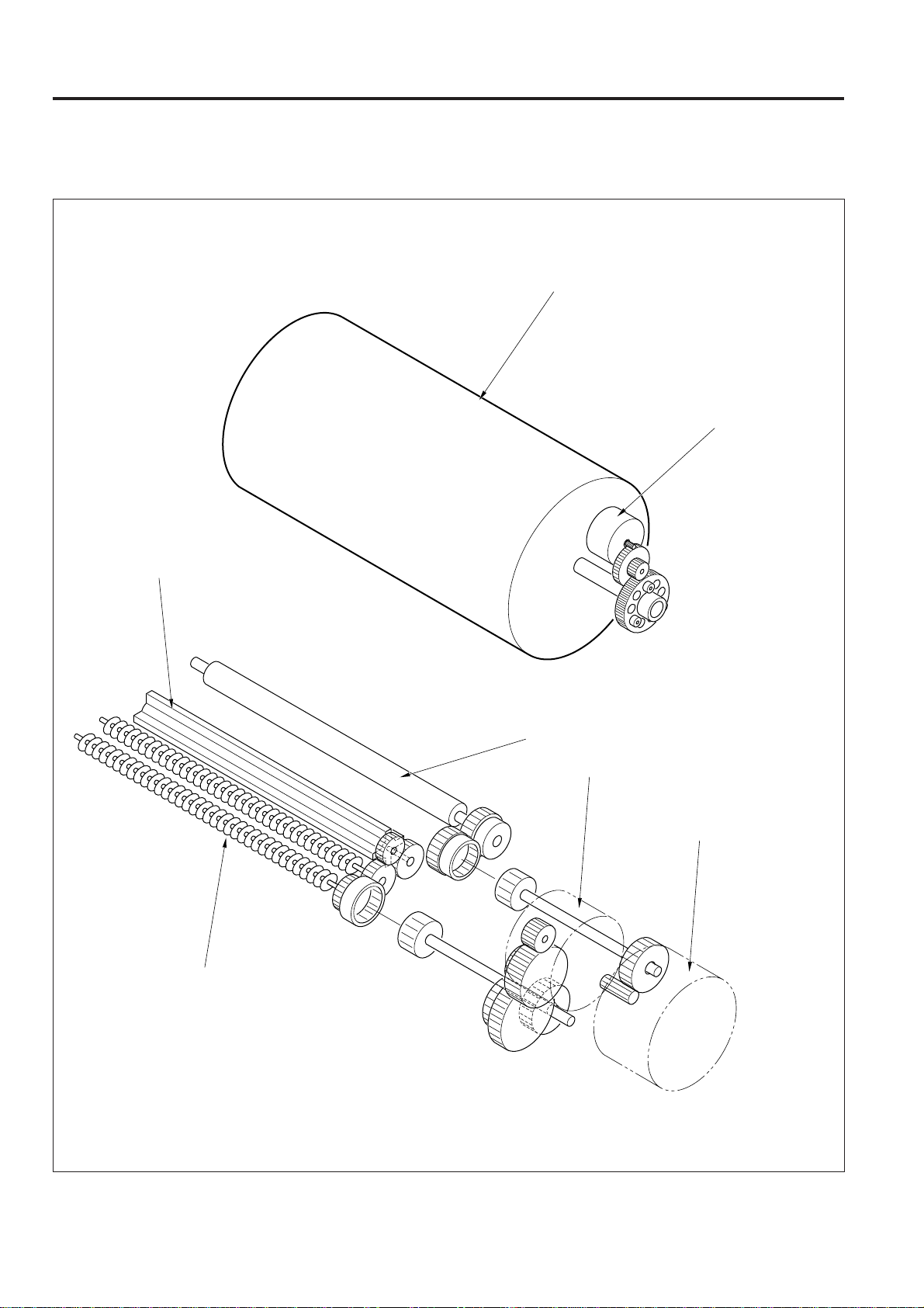
[1] Main Drive
Conveyance belt
Toner conveyance screw
DRIVE SYSTEM DIAGRAM
Decurler unit
2nd paper feed roller
Main Motor
(M1)
Cleaner MC
(MC 10)
A
Timing belt
2nd paper feed MC (MC3)
2 - B - 1
Page 8
DRIVE SYSTEM DIAGRAM
[2] Drum/Developing Drive
Drum
Drum motor (M4)
Agitator wheel
Agitator screw
Developing sleeve
Agitator screw motor (M35)
Developing drive
motor (M3)
2 - B - 2
Page 9
B
A
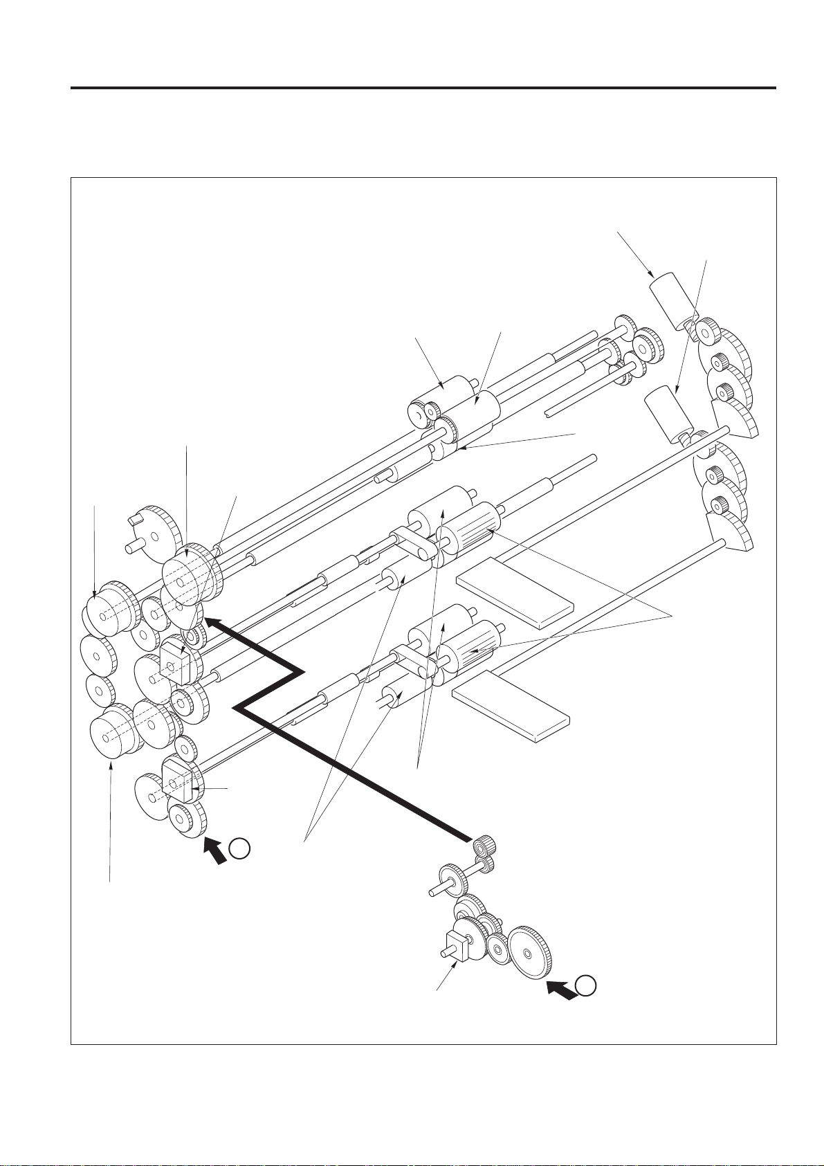
[3] Paper Feed Drive
DRIVE SYSTEM DIAGRAM
Upper tray motor (M17)
Lower tray motor
(M18)
By-pass paper feed MC
(MC7)
Middle conveyance
MC1 (MC8)
Paper feed MC
(Upper tray) (MC5)
By-pass paper feed roller
By-pass roller
Double feed
prevention roller
Paper feed rollers
Middle conveyance MC2
(MC9)
Paper feed MC
(Lower tray)
(MC6)
Double feed
prevention rollers
Feed rollers
Assist drive MC (MC11)
2 - B - 3
Page 10

DRIVE SYSTEM DIAGRAM
[4] ADU Paper Feed/Conveyance Drive
Timing belt
Paper exit rollers
ADU paper feed motor
(M151)
Timing belt
ADU timing CL (CL153)
Timing belt
Timing belt
Paper exit rollers
ADU reversal MC (CL152)
Conveyance roller
ADU paper feed MC (CL151)
2 - B - 4
Reversal roller
Page 11

[5] 1000-Tray Paper Feed/Conveyance Unit
Conveyance roller (upper)
LCT conveyance CL (CL3)
DRIVE SYSTEM DIAGRAM
Conveyance roller (lower)
LCT 1st paper feed CL (1000)
(CL1)
Feed roller
Paper feed roller
Double feed prevention roller
2 - B - 5
Page 12

DRIVE SYSTEM DIAGRAM
[6] 1500-Tray Paper Feed/Conveyance Unit
B
Timing belt
Horizontal conveyance
rollers
Feed roller
C
Paper
feed roller
Timing belt
Double feed prevention roller
LCT 1st paper feed CL
(1500) (CL2)
LCT paper feed motor (M140)
2 - B - 6
Page 13

[7] Reversal/Paper Exit Unit
DRIVE SYSTEM DIAGRAM
Paper exit conveyance roller (upper)
Paper exit conveyance roller (middle)
Paper exit conveyance roller (lower)
Paper exit motor
(M202)
Timing belt
Reversal paper exit motor
(M201)
2 - B - 7
Page 14

EXTERNAL SECTION
[1] Composition
EXTERNAL SECTION
Left side
upper
cover
Left side
lower cover
Lower tray
Main switch
ADU
LCT-1500
tray
Front door
Operation panel
Upper tray
Paper feed and
conveyance door
LCT-1000
tray
By-pass feed
table
LCT conveyance
door
Right side
upper cover
RADF
Outer I/F
connectors
Rear cover
Right side lower cover
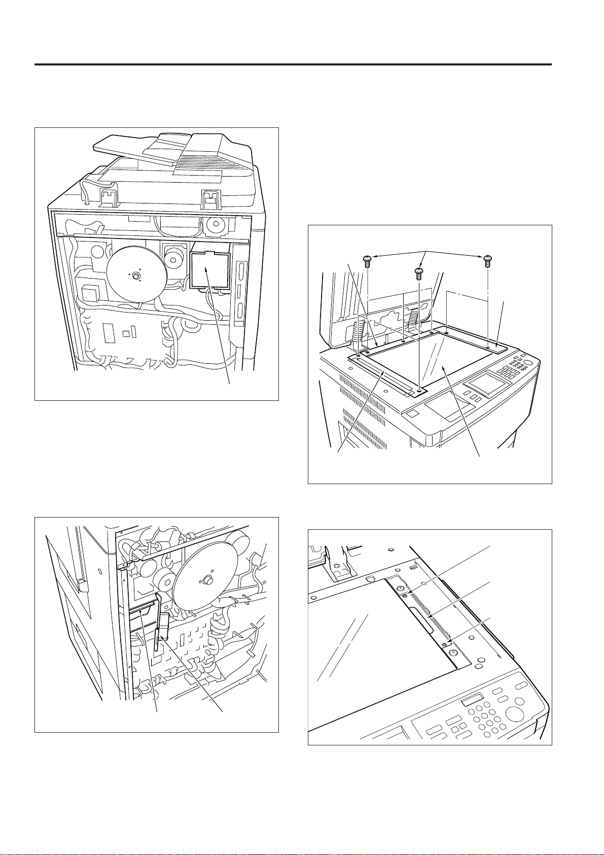
[2] Disassembly and Re-assembly
1. Replacing the Ozone Filter (K)
Caution: Be sure that the power cord has been un-
plugged from the power outlet.
Caution: When replacing the ozone filter (K), ensure the new
filter is fitted securely inside the main body.
a. Procedure
(1) Remove the nine set screws, then remove the rear
cover.
Set
screws
Set
screws
Rear cover
Set screws
2 - C - 1
Page 15
EXTERNAL SECTION
(2) Pull the ozone filter (K) forward and remove it.
Ozone filter (K)
3. Replacing the Dust Proof Filter Assembly
Caution: Be sure to install the dust proof filter so that the filter
material is on the finisher side of the assembly.
a. Procedure
(1) Open the RADF.
(2) Remove the two set screws, then remove the original
stopper plate (rear/right).
(3) Remove the five set screws, then remove the original
stopper plate (rear/right).
Original
stopper plate
(rear)
Set screws
Original
stopper plate
(right)
(3) Re-install the ozone filter in the opposite sequence to
removal.
2. Replacing the Developing Suction Filter
a. Procedure
(1) Remove the rear cover.
(2) Release the lock, open the filter box, and remove the
developing suction filter.
Original stopper plate
Platen glass
(4) Loosen the two set screws, and remove the glass fixing
plate/right.
Set screw
Glass fixing
plate/right
Set screw
Filter boxDeveloping suction filter
(3) Re-install the suction filter in the opposite sequence to
removal.
(5) Remove the platen glass.
2 - C - 2
Page 16

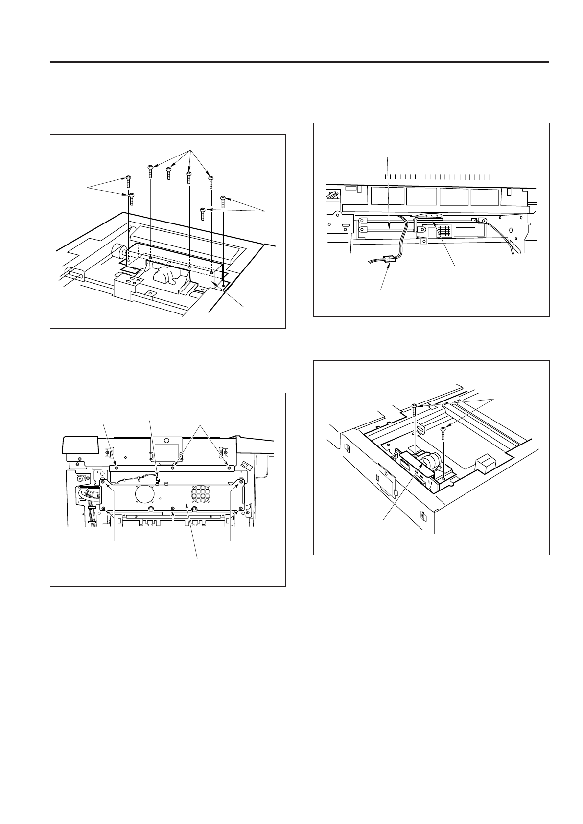
(6) Remove the four set screws to open the bypass table,
and remove the upper cover (middle).
Set screws
Set screws
EXTERNAL SECTION
Upper cover (middle)
(7) Remove the dust proof filter ass’y, then install the new
dust proof filter ass’y.
Dust proof filter ass'y
(8) Re-install the removed parts in the reverse sequence
to removal.
2 - C - 3
Page 17

DRIVE SECTION
[1] Composition
DRIVE SECTION
Drum motor (M4)
Agitator screw motor (M35)
Developing drive motor (M3)
Assist drive clutch (MC11)
Main motor (M1)Drum drive unit
[2] Mechanisms
Mechanism Method
*1
Drum drive Gear drive (dedicated motor)
*1
Developing sleeve drive Gear drive (dedicated motor)
*1
Developing agitator drive Gear drive (dedicated motor)
2nd paper feed drive Timing belt + gear drive
Conveyance drive Timing belt + gear drive
Fixing and paper exit drive Timing belt + gear drive
ADU lead-in drive Timing belt + gear drive
Toner recycle Timing belt + gear drive
*2
Loop assist drive Clutch + gear drive
*1: Separation of the different parts of the drive system
The drum, developing sleeve and developing agitator of
this machine are driven by separate motors in order to
improve the serviceability of the drum unit and also to
improve the developing performance.
*2: Loop assist drive
Drive which is supplied to the 2nd paper feed roller is also
transmitted to the middle conveyance roller in order to
stabilize the loop formation before the 2nd paper feed
roller. This drive is transmitted from the drive section via the
assist drive clutch (MC11) during loop formation.
Loop
Middle conveyance
roller
Drive section
2nd
paper feed roller
Assist drive clutch
(MC11)
2 - D - 1
Page 18
DRIVE SECTION
[3] Disassembly and Re-assembly
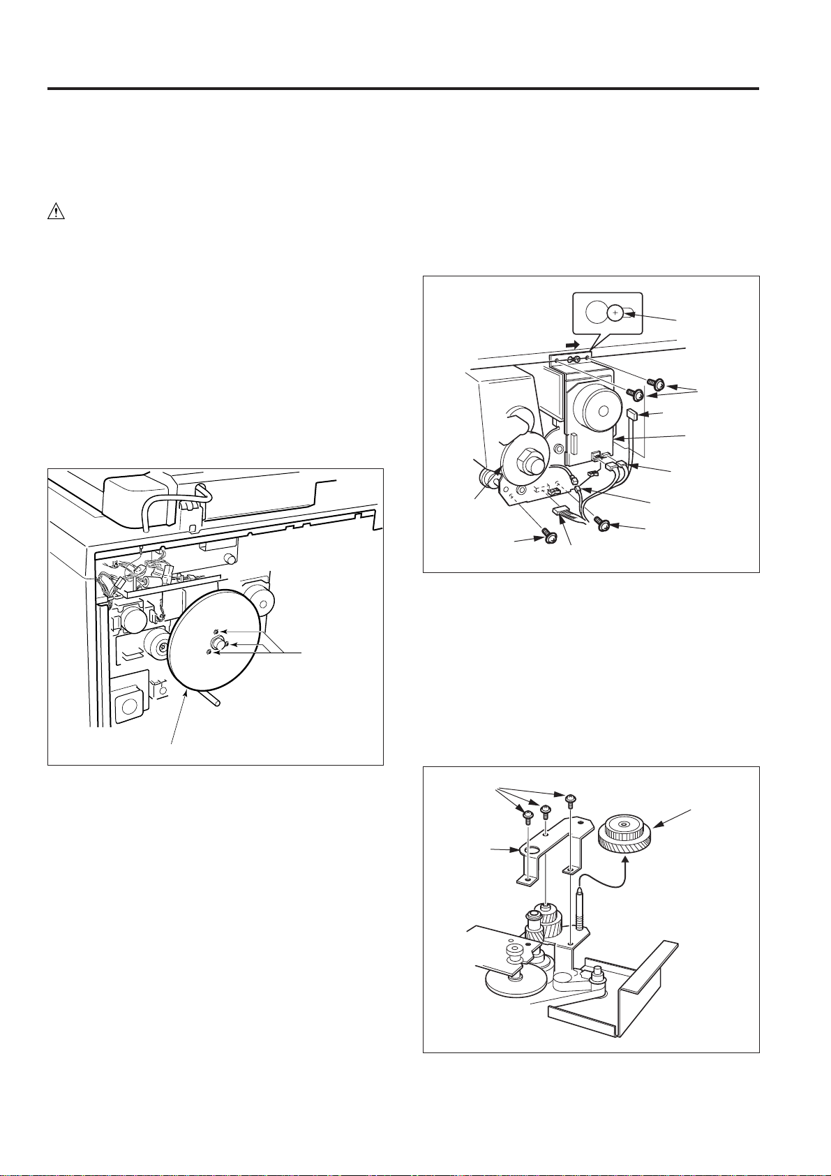
1. Removing and Re-installing the Main Motor
Unit
Caution: Be sure that the power cord has been un-
plugged from the power outlet.
Caution: Be sure to remove the drum unit before removing or
re-installing the main motor unit.
If you leave the drum unit installed, the cleaning
blade is likely to be damaged because the drum will
turn when you remove or re-install the flywheel.
a. Procedure
(1) Remove the drum unit from the main body. (Refer to
"Drum unit section".)
(2) Remove the nine set screws, then remove the rear
cover.
(3) Remove the three set screws, then remove the fly-
wheels (three).
(4) Disconnect the relay connector and the four connec-
tors (CN16, 204, 205 and 324), then remove the cable
from the wiring clamp.
(5) Remove the four set screws, slide the main motor unit
to the right, then pull it forward and remove it.
Caution: DO NOT strike the main motor unit against the drum
drive gear when removing or re-installing it.
Slotted hole
Guide screw
Set screws
Connector (CN16)
Main motor
unit
Connectors
(CN204, 205)
Drum
drive gear
Set screw
Connector (CN324)
Relay
connector
Set screw
Flywheels
Set
screws
(6) Re-install the main motor unit in the opposite sequence
to removal.
2. Replacing the Paper Feed Drive Shaft and
Fixing Input Gear
a. Procedure
(1) Remove the main motor unit.
(2) Remove the three set screws, then remove the fixing
drive plate.
(3) Remove the fixing input gear.
Set screws
Fixing input
gear
Fixing drive
plate
2 - D - 2
Page 19

DRIVE SECTION
(4) Remove the four set screws, then remove the paper
feed drive plate.
Set screws
Paper feed drive plate
Set screw
(5) Remove the drive spacer and the paper feed input gear.
Caution: Do not forget to re-install the drive spacer when re-
installing the paper feed input gear.
(6) Remove the bearing and developing drive gear, then
pull out the pin remaining in the paper feed drive shaft.
(7) Remove the main body drive belt from the drive pulley.
(8) Remove the E ring from the paper feed drive shaft, then
remove the drive pulley.
(9) Remove the paper feed drive shaft, then pull out the pin
remaining in the paper feed drive shaft.
3. Replacing the Assist Drive Clutch (MC11)
a. Procedure
(1) Remove the nine set screws, then remove the rear
cover.
(2) Remove the three set screws, then remove the fly
wheels (3 wheels).
(3) Remove the set screw and the connector (CN86), then
remove the wiring support element. (Refer to the 2nd
paper feed unit removing/re-installing of the paper
feed section.)
(4) Remove the two set screws, then remove the convey-
ance clutch shaft ass’y.
(5) Remove the connector (CN169).
(6) Remove the E ring, then remove the drive shaft bearing.
(7) Loosen the set screw, then remove the assist drive
clutch (MC11).
Setting screw
Assist drive
clutch (MC11)
Drive shaft
bearing
E ring
Connector
(CN169)
Set screw
Bearing
Paper feed drive shaft
Pins
Drive spacer
Paper feed
input gear
Developing
drive gear
E ring
Drive pulley
Main body drive belt
(10)Re-install the above parts in the opposite sequence to
removal.
Set screw
(8) Re-install the above parts in the opposite sequence to
removal.
2 - D - 3
Page 20

DRIVE SECTION
[4] M1 (main) Control [5] M4 (drum) Control
40VDC
DCPS
CB
PGND
5VDC
M1 CONT
M1 PLL
SGND
M1 CLK
88-5
88-3
M1
30-A1
30-A3
30-A4
30-A5
30-A2
24VDC
PGND
DCPS
5VDC
SGND
M4 CONT
M4 H/L
M4 CLK
M4 PLL
CB
99-2
99-5
30-A8
30-A9
30-A10
30-B6
30-A11
30-A12
M4
M1 (main) is controlled by the CB (control board).
1. Operation
M1 is a 40 V drive DC motor which drives the toner recycle,
conveyance, 2nd paper feed and fixing sections. M1 is
PLL-controlled by feedback signals from a speed sensor
installed inside M1 itself, maintaining it at a constant speed.
M1 goes ON when the Start button is pressed, and goes
OFF again when the final copy has been exited.
During warm-up, M1 rotates, causing the fixing roller to
rotate.
2. Signals
a. Input signal
(1) M1 PLL (M1 → CB)
M1 rotation monitoring signal
[H]: Stop or abnormal or rotation
[L]: Normal rotation
b. Output signals
(1) M1 CONT (CB → M1)
M1 drive control signal
[L]: M1 ON
[H]: M1 OFF
(2) M1 CLK (CB → M1)
M1 rotational speed control reference clock signal
M4 (drum) is controlled by the CB (control board).
1. Operation
M4 is a 24 V drive DC motor which drives the drum and the
cleaning guide roller. M4 is PLL-controlled by feedback
signal from a speed sensor installed inside M4 itself,
maintaining it at a constant speed.
M4 goes ON when the start button is pressed, and goes
OFF again when the final copy has been exited.
2. Signals
a. Input signal
(1) M4 PLL (M4 → CB)
[L] is output when M4 reaches the specified speed.
b. Output signals
(1) M4 CONT (CB → M4)
M4 drive control signal
[L]: M4 ON
[H]: M4 OFF
(2) M4 H/L (CB → M4)
M4 rotational speed control gain switchover signal
Normally [H]: 370 mm/sec
[L]: 185 mm/sec
(3) M4 CLK (CB→M4)
M4 rotational speed control reference clock signal
2 - D - 4
Page 21

READ SECTION
[1] Composition
READ SECTION
CCD unit
Optics cooling fan (FM2)
Optics drive wire
Optics rail (R)
Exposure unit
V mirror unit (2nd and 3rd mirrors)
A/D converter board (ADB)
[2] Mechanisms [3] Disassembly and Re-assembly
1. Screws that must not be removed
Mechanism Method
Light source Xenon lamp
Exposure Light source shift slit exposure
Scanning Platen original scanning:
1st, 2nd, 3rd mirror shift
RADF original scanning:
Fixed light source/Original moving
Lamp power supply Lamp cord
Cooling of optics Cooling of intake air using a fan
a. The 14 set screws of the CCD unit
Screws that must
not be removed
Screws that must
not be removed
2 - E - 1
Screws that must
not be removed
Screws that must
not be removed
Page 22

READ SECTION
b. The read positioning plate set screw and the two
glass stopper plate (right) set screws.
Read positioning
plate
Screw that must
not be removed
Screws that must
not be removed
Glass stopper
plate (right)
2. Removing and Re-installing the CCD Unit
Caution: Be sure that the power cord has been un-
plugged from the power outlet.
Caution: Be sure to perform image adjustment after installing
the CCD unit. (For details, refer to "Adjustment
section".)
a. Procedure
(1) Remove the original stopper plate, original stopper
plate (right/rear), platen glass and upper cover (middle).
(2) Remove the two set screws, then remove the glass
stopper plate.
Set screws
Glass stopper plate
(3) Remove the two set screws, then remove the lens light
blocking cover 2.
Set screws
Lens light
blocking cover 2
2 - E - 2
Page 23
READ SECTION
(4) Remove the eight set screws, then remove the lens
light blocking cover 1.
Set screws
Set
screws
Set
screws
Lens light
blocking
cover 1
(5) Remove the left side upper cover.
(6) Disconnect the connector (CN49).
(7) Remove the eight set screws, then remove the fan
mounting plate.
(8) Disconnect the two connectors (CN420 and 412).
Electronic RDH processing
board (E-RDH)
Connector (CN420)
Connector (CN412)
(9) Remove the two set screws, then remove the CCD
unit.
Set screw
Set screws
Connector (CN49)
Set screw Set screws
Fan mounting plate
Set screws
Set screws
CCD unit
(10) Re-install the CCD unit in the opposite sequence to
removal.
2 - E - 3
Page 24

READ SECTION
3. Replacing the Exposure Lamp
Caution:
1. Be sure that the power cord has been unplugged
from the power outlet.
2. DO NOT touch the glass of the exposure lamp with
bare hands.
Caution:
Be sure to check the image after installing the exposure lamp. (For details, refer to "Adjustment section".)
a. Procedure
(1) Remove the original stopper plate, original stopper
plate (right/rear), platen glass and the upper cover
(middle).
(2) Move the exposure unit to the notch of the main body
frame on the paper exit side.
(3) Disconnect the connector and remove the two set
screws, then remove the exposure lamp.
Set screws
Exposure lamp
Connector
4. Removing and Re-installing the Exposure Unit
Caution: Be sure that the power cord has been un-
plugged from the power outlet.
Caution:
1. Use the optics positioning jig when installing the exposure unit.
2. Be sure to perform image adjustment after installing
the exposure unit. (For details, refer to "Adjustment
section".)
a. Removal procedure
(1) Remove the original stopper plate, original stopper
plate (right/rear), platen glass and upper cover (middle).
(2) Remove the seven set screws, then remove the opera-
tion panel and disconnect the three connectors (CN219,
222 and 383).
Connector (CN383)
Set screws
Connector
(CN222)
Connector
(CN219)
(4) Re-install the exposure lamp in the opposite sequence
to removal.
2 - E - 4
Operation
panel
Set screws
(3) Move the exposure unit to the notch of the main body
frame on the paper exit side.
(4) Remove the set screw, then remove the cord retaining
material (B) and disconnect the connector (CN29).
(5) Remove the four set screws, then remove the expo-
sure unit.
Page 25

Set screws
Connector
(CN29)
Exposure unit
Set screws
Set screw
READ SECTION
5. Installing the Optics Wire
Caution:
1. When winding the wire around the pulley, be sure to
run the wire tightly to ensure that it does not ride up the
side of the pulley.
2. When re-tensioning or replacing the optics wire, be
sure to use the optics positioning jig.
3. Be sure to perform image adjustment after replacing or
re-installing the wire. (For details, refer to "Adjustment
section".)
a. Procedure
(1) Remove the exposure unit.
(2) Remove the glass stopper plate.
(3) Remove the two set screws, then remove the belt of the
front door from the main body.
(4) Disconnect the two connectors (CN381 and 41).
(5) Remove the five set screws, then remove the right side
upper cover.
(6) Remove the five set screws, then remove the front
cover/lower.
Cord retaining
material (B)
b. Re-installation procedure
(1) Insert the Optics positioning jig into the exposure unit
mounting position from the front.
(2) Slide the exposure unit to the paper feed side until it
touches the Optics positioning jig.
Exposure unit
Connector (CN381)
Set
screw
Set screws
Set screws
Connector (CN41)
Front cover/lower
Set
screw
Front door
Optics positioning jig
(3) Install the exposure unit on the optics wire mounting
piece using the four set screws.
2 - E - 5
Page 26

READ SECTION
(7) Move the V mirror unit to the paper feed side, then
insert the optics positioning jigs from the front so as to
fix the V mirror unit. Ensure that the jigs pass through
the V mirror unit.
(8) Insert the Optics positioning jigs to the exposure unit
mounting position from the front.
Exposure unit
V mirror unit
Optics positioning jigs
(9) The exposure unit mounting piece is installed on the
optics wire in advance. The position of the mounting
piece differs depending upon whether it is on the front
or the rear wire. Use the wire that has the shorter length
from the metal bead at the end to the mounting piece,
at the rear.
(10)Place the metal bead at the mid-point of each optics
wire in the mounting hole of the drive pulley, then wind
five turns around the pulley to the outside, and four
turns to the inside, starting from this point.
Caution:
1. Ensure that there is a metal bead at the end of the outer
wire, and a wire terminal at the end of the inner wire.
2. Pull out the outer wire from the top of the drive pulley
in the paper exit direction, and pull out the inner wire
from the bottom of the drive pulley in the paper feed
direction.
(11)After winding the outer wire, fix it to the wire stopper via
the outer side of pulley 1 and the V mirror pulley.
2 - E - 6
Page 27

READ SECTION
Five
10 10 11
Front
turns
Four
turns
Four
turns
Five
turns
Rear
Wire stopper
Metal bead
Metal bead
Drive pulley
Optics wire (front)
Wire stopper
11
Pulley 1
Exposure unit
mounting piece
Metal bead
Wire
stopper
Metal bead
Optics wire (rear)
Metal bead
Spring
V mirror unit
Spring fixing plate
V mirror unit
12 13
Set screws
Pulley 1
Rear
Pulley 3
Pulley 2
Spring fixing plate
Metal bead
Wire stopper
Pulley 1
V mirror unit
9
Optics wire (rear)
Optics wire (front)
Note: There are two grooves in the wire stopper. Ensure that
the outer groove is at the rear and the inner groove at
the front.
(12)Pass the inner wire through the notch in the wire
stopper, reverse it at pulley 2, then pass it around the
inside of the V mirror pulley and also around pulley 3,
in that sequence, and attach the wire terminal to the
spring fixing plate. At this time, temporarily fix the
spring fixing plate with the set screw.
Exposure unit
Metal bead
mounting piece
Metal bead
Wire terminal
(13)Install the other wire using the same procedure.
(14) Slacken each screw that was temporarily fixed, then
install the spring on the spring fixing plate and fix the
each screw once again.
2 - E - 7
Page 28

READ SECTION
[4] M12 (optics drive) Control
M12 H/L
M12 CLK
M12 M STOP
M12 MODE 0
M12 MODE 1
M12 MODE 2
M12 F/R
M12 CONT
M12
BRAKE
M12 NCR
M12 PLL
SGND
PS2
5VDC
PS4
PS5
PS7
PS8
PS28
SGND
PS3
5VDC
PS9
PS29
CB
223-1
223-2
223-3
223-4
223-5
223-6
223-7
223-8
223-9
223-10
223-11
9-A1
9-A2
9-A3
9-A5
9-A6
9-A7
9-A9
9-B3
9-B6
9-B5
9-B8
9-B2
9-B9
224-1
224-2
224-3
224-4
224-5
224-6
224-7
224-8
224-9
224-10
224-11 M12 PLL
OPMDB
76-1
76-2
76-3
73-1
73-2
73-3
66-1
66-2
66-3
74-1
74-2
74-3
67-1
67-2
67-3
110-1
110-2
110-3
72-1
72-2
72-3
75-1
75-2
75-3
111-1
111-2
111-3
M12 DRIVE C
M12 DRIVE A
M12 DRIVE B
M12 MAG A'
M12 MAG A
M12 MAG B'
M12 MAG B
M12 MAG C'
M12 MAG C
SGND
5VDC
M12 FG
PS2
PS4
PS5
PS7
PS8
PS28
PS3
PS9
PS29
225-1
225-2
225-3
228-1
228-2
228-3
228-4
228-5
228-6
228-7
228-8
228-9
226-5
226-1
226-2
226-3
400-4
400-1
400-2
400-3
M12
SGND
40VDC
PGND
12VDC
DCPS
1. Operation
a. Operation of M12
M12 is a 3-phase brushless DC motor which is driven using
a 3-phase bipolar method. The current flowing through the
windings is switched according to the position of the rotor
which is detected by a sensor (magnetic sensor) inside the
motor.
b. Moving speed of the exposure unit
Moving speed
Magnification Moving speed
During scanning 370 mm/sec (life size)
Forward 1520 mm/sec
Home position search 70 mm/sec
Shading correction read 70 mm/sec
c. Position of each sensor
Paper feed side
PS9 PS29 PS3
d. Home position search of the exposure unit
The return operation is executed at low speed when the
exposure unit is not at the home position during the main
switch ON and the start button is pressed, and detects the
home position of the exposure unit when PS9 (ADF home
position) is OFF and PS29 (ADF brake) is ON.
e. Shading correction read operation
At the position where PS3 (shading position) goes ON, the
light reflected from the white reference plate installed
under- neath the glass stopper plate is read.
Home position
(PS9 OFF, PS29 ON
PS3 OFF)
White correction data collecting
PS28 PS2 PS4
PS9 ON,
PS29 OFF,
PS3 OFF
PS5 PS7
PS9 OFF,
PS29 OFF,
PS3 ON
L1 ON
M12 (optics drive) is driven by the OPMDB (optics motor drive
board), and is controlled by the CB (control board).
Related signals are PS2 (scanner brake), PS3 (shading position), PS4 (paper feed restart), PS5 (optical return), PS7
(optical timing), PS8 (glass detection), PS9 (ADF home position), PS28 (scan EE), and PS29 (ADF brake).
Black correction
data collecting
L1 OFF
2 - E - 8
Page 29

READ SECTION
f. Other operations
(1) During copying (manual, EE)
Start button
pressed
EE scan
Exposure scan
(2) Non-image area erase (+ Book copy)
(3) Book copy (EE)
Start button
pressed
EE scan
Exposure scan (page 1)
Exposure scan (page 2)
Start button
pressed
EE, Size detection scan
Exposure scan (page 1)
Exposure scan (page 2)
2 - E - 9
Page 30

READ SECTION
2. Signals
a. Input signals
(1) PS2 (PS2 → CB)
The brake is applied to M12 after the specified period
from when PS2 goes ON during the forward scan of the
exposure unit
[L]: Exposure unit detected
[H]: Exposure unit not detected
(2) PS3 (PS3 → CB)
White reference plate read position detection signal of
the exposure unit
[L]: The exposure unit is in the white reference plate
read position.
[H]: The exposure unit is not in the white reference
plate read position.
(3) PS4 (PS4 → CB)
Original leading edge detection signal during platen
mode
The timer that determines the 2nd paper feed start
timing starts when PS4 goes ON during the exposure
unit
[L]: Exposure unit detected
[H]: Exposure unit not detected
(4) PS5 (PS5 → CB)
Return position detection signal of the exposure unit on
the leading edge of the original during platen mode
[L]: Exposure unit detected
[H]: Exposure unit not detected
(5) PS7 (PS7 → CB)
Return position detection signal of the exposure unit on
the leading edge of the original during platen mode
[L]: Exposure unit detected
[H]: Exposure unit not detected
(6) PS8 (PS8 → CB)
Signals to detect the setting of the original glass
[L]: Original glass detected
[H]: Original glass not detected
(7) PS9 (PS9 → CB)
Signals to detect the home position of the exposure
unit
[L]: Exposure unit detected
[H]: Exposure unit not detected
(8) PS28 (PS28 → CB)
Signals to detect the EE scan (exclude photo mode,
non-image area erase mode) starting position of the
exposure unit
[L]: Exposure unit detected
[H]: Exposure unit not detected
(9) PS29 (PS29 → CB)
Signals to detect the home position and the M12 brake
starting position during return of the home position of
the exposure unit
[L]: Exposure unit detected
[H]: Exposure unit not detected
(10)M12 PLL (OPMDB → CB)
[L] is output when M4 reaches the specified speed.
(11)M12 MAG A/A' (M12 → OPMDB)
M12 MAG B/B' (M12 → OPMDB)
M12 MAG C/C' (M12 → OPMDB)
These are the output signals from the sensors (magnetic sensors) contained in M12. OPMDB detects the
position of the rotor of the motor by means of these
signals, and switches over the M12 DRIVE A to C
output.
(12)M12 FG (M12 → OPMDB)
This is a feedback signal from the rotational speed
sensor contained in M12. It is compared with the M12
CLK signal from the CB, and the output voltage adjusted so that the feedback signal becomes the same
as the M12 CLK signal, thus controlling the rotational
speed of M12.
2 - E - 10
Page 31

READ SECTION
2-1
2-3
61-1
61-2
DCPS1
PGND
L1 CONT
24VDC
60-B8
60-A9
60-A10
24VDC
PGND
CB
INVB
L1
LVHV385-1
385-4
29-3
29-2
29-1
b. Output signals
(1) M12 DRIVE A, B, C (OPMDB → M12)
This is the M12 drive signal. While M12 is rotating,
voltages are output sequentially from M12 DRIVE A to
C, and applied to M12.
The voltage from each output that is applied to M12
consists of the pulses shown below. The pulse width
of this output changes according to the rotation condition of M12, as shown in the figure, and as a result the
RMS value of the voltage applied to M12 changes,
causing the speed to be regulated.
M12 DRIVE A
M12 DRIVE B
M12 DRIVE C
(2) M12 CONT (CB → OPMDB)
M12 ON/OFF control signal
[L]: M12 ON
[H]: M12 OFF
(3) M12 CLK (CB → OPMDB)
M12 rotational speed control reference clock signal
(4) M12 F/R (CB → OPMDB)
Signal used to control the rotational direction of M12
[L]: Forward operation
[H]: Return operation
(5) M12 BRAKE (CB → OPMDB)
M12 brake control signal
(6) M12 NCR (CB → OPMDB)
M12 brake control signal
(7) M12 MODE 0, 1, 2 (CB → OPMDB)
M12 rotational speed control signal
Eight rotational speed modes are activated by combinations of these three signals.
[5] Exposure control
Power is supplied to L1 (exposure lamp) from the INVB
(inverter board) and is controlled by the CB (control board).
1. Operation
L1 is a xenon lamp which is driven by an inverter circuit. A
xenon lamp provides a stable light intensity and also generates
relatively little heat, hence it does not require a light intensity
control circuit that is used in conventional copying machines,
and also protective control that is normally required due to heat
generation from the lamp is no longer used.
2. Signal
a. Output signal
(1) L1 CONT (CB → INVB)
L1 ON/OFF control signal
[L]: L1 ON
[H]: L1 OFF
2 - E - 11
Page 32

READ SECTION
[6] Original Read Control
425-A1 481-A1
425-A12 481-A12
425-B1 481-B1
425-B12 481-B12
CB
The original is read by the ADB (A/D converter board) and the
CCD image sensor installed on the ADB.
1. Operation
The light reflected off the exposed original passes through a
lens to the CCD image sensor. The analog voltages that
correspond to the input light intensity are A/D-converted in the
ADB, and output to the IPB (image processing board).
a. Original read operation
The original read timing is as follows.
(1) During a platen copy operation
When PS4 (paper feed restart) goes ON.
(2) During a DF copy operation
After the specified time from the ON of PS308 (original
conveyance) by original leading edge.
IPB
420-40
420-1
411-1
CCD
ADB
411-40
[7] APS Control
SGND
9-B6
PS45
9-B7
5VDC
9-B8
SGND
22-A7
PS40
22-A6
5VDC
22-A5
PS41
22-A8
PS42
22-B1
PS43
22-B2
PS48
22-A3
CB
The APS differs depending upon whether the platen mode or
the DF mode is used. The APS control is carried out by
processing the signal of the RADF original size detection
sensor read by CB (control board).
1. Operation
a. APS detection operation
(1) During a DF copy operation
A paper size is detected by ON or OFF of PS302 (original
size detect 1) and PS303 (original size detect 2) of the
paper feed tray of RADF, and resistance value of VR301
(original size detect).
(2) During a platen copy operation
APS detection is an operation that detects the paper
size according to the particular ON/OFF combination
of PS40 (APS 1), PS41 (APS2), PS42 (APS 3), PS43
(APS 4) and PS48 (APS 7).
The APS sensor consists of LEDs and photosensors.
APS detection takes place as a result of the light
emitted from each LED being reflected off the original
and received by the photosensor.
137-1
137-2
137-3
133-1
133-2
133-3
134-1
134-2
134-3
130-1
130-2
130-3
138-1
138-2
138-3
239-1
239-2
239-3
PS45
PS40
PS41
PS42
PS43
PS48
2 - E - 12
Paper exit side
PS41
PS40
Photosensor
LED
PS48
PS42
PS43
Page 33

READ SECTION
The relation between each sensor and the paper size is
shown below.
Sensor
Paper size
A3
B4
A4R
B5R
A4
B5
Minimum size
b. APS detection timing
The APS detection timing differs depending upon whether the
platen mode or the DF mode is used.
(1) During a DF copy operation
When either the DF mode is selected or an original is
placed in the RADF paper feed tray, the original size is
detected by PS302 (original size detect 1), PS303
(original size detect 2) and VR301 (original size detect).
(2) During a platen copy operation
APS detection takes place when PS45 (APS timing)
goes ON.
APS detection stops when PS45 goes OFF.
PS40
PS302
ON
ON
ON
OFF
OFF
OFF
OFF
PS41
PS303
PS42
ON
ON
OFF
OFF
OFF
OFF
OFF
ON
ON
OFF
OFF
ON
ON
OFF
PS43
ON
OFF
OFF
OFF
ON
OFF
OFF
PS48
ON
ON
ON
ON
ON
ON
OFF
(5) PS45 (PS45 → CB)
RADF opening/closing detection signal
Activates or deactivates the APS function during a
platen copy operation.
[L]: ON (APS function activated)
[H]: OFF (APS function deactivated)
RADF(DF-312)
PS45 goes ON
(6) PS48 (PS48 → CB)
Paper size detection signal
[L]: Paper is detected.
[H]: Paper is not detected.
2. Signals
a. Input signals
(1) PS40 (PS40 → CB)
Paper size detection signal
[L]: Paper is detected.
[H]: Paper is not detected.
(2) PS41 (PS41 → CB)
Paper size detection signal
[L]: Paper is detected.
[H]: Paper is not detected.
(3) PS42 (PS42 → CB)
Paper size detection signal
[L]: Paper is detected.
[H]: Paper is not detected.
(4) PS43 (PS43 → CB)
Paper size detection signal
[L]: Paper is detected.
[H]: Paper is not detected.
2 - E - 13
Page 34

READ SECTION
[8] EE Control
425-A1 481-A1
425-A12 481-A12
425-B1 481-B1
425-B12 481-B12
CB
EE control takes place during an EE scan as a result of the CCD
image sensor reading the original density and selecting the
most suitable copy γ correction curve.
EE processing is performed by the IPB (image processing
board).
1. Operation
a. EE detection operation
(1) During Platen mode (normal)
Density is measured in the following range with PS28
(scan EE) being the starting point when the exposure
unit moves from the home position to the leading edge
of the original by turning the start button ON.
<EE sampling area>
Main scanning direction: 182mm from rear side of an
Sub scanning direction: 182mm from when PS28
IPB
420-40
420-1
original
goes ON
411-1
CCD
ADB
411-40
(2) During Platen Copy (during photo mode, non-image
area erase mode)
Density is measured in the following range by executing EE scan as PS4 (paper feed restart) being the
starting point when the exposure unit moves from the
home position to the leading edge of the original by
turning the start button ON.
<EE sampling range>
Photo mode:
Main scanning direction: 182mm from rear side of an
original
Sub scanning direction: 182mm from when PS4
goes ON
Non-image area erase mode:
Entire size detected by size detection scan
(3) During a DF copy mode
The image at the leading edge of the original is read by
the original feed operation that takes place when the
start button is pressed, and the read data is used to
perform density measurement.
<EE sampling area>
1) Main scanning direction
• An area of 20 mm inward of the original size
detected by the APS
• If the original size cannot be determined by the
APS, an area of 20 mm inward of the minimum
original size set for the particular shipping destination of the machine.
2) Sub scanning direction
An area between 1 mm and 4 mm from the leading
edge of the original
2 - E - 14
Page 35

WRITE UNIT
[1] Composition
WRITE UNIT
Index mirror
Index sensor board
Laser driver board 1
Laser driver board 2
Collimator lens unit 2
[2] Mechanisms
Mechanism Method
*1
Scan Polygon mirror
(Rotational speed: 21850.4 rpm)
(400 dpi standard mode)
Light source Laser diodes (two)
(Output: Max. 35 mW)
*2
Positioning Index sensor
Fine adjustment prism
*3
Laser beam combining Beam combining prism
*1: Path of laser beam
The light output to each semiconductor laser is sent to the
OPC drum via the collimator lens, compression prism, fine
adjustment prism, beam combining prism, cylindrical lens
1, polygon mirror, fθ lens, 2nd mirror, cylindrical lens 2, and
the 3rd mirror.
Collimator lens unit 1
2nd mirror
Beam combining prism
Polygon mirror
3rd mirror
Stepping
motor
Compression
prism
Semiconductor
laser LD1
Glass cover
Index mirror
Index sensor
OPC drum
Cylindrical lens 2
3rd mirror
Polygon mirror
Polygon driver board
CY2 lens
Cylindrical lens 1
fθ lens
fθ lens unit
Fine
adjustment
prism
2nd mirror
CY1 lens
Beam
combining prism
Compression
prism
Collimator
lens unit
Semiconductor
laser LD2
2 - F - 1
Page 36

WRITE UNIT
*2: Positioning
Each laser beam is positioned by the compression prism
and the fine adjustment prism.
*3: Combining the laser beams
The two laser beams are output at right angles with respect
to each other. The beam combining prism causes them to
be output in the same direction.
Semiconductor laser 1
Beam combining prism
Semiconductor laser 2
[3] Disassembly and Re-assembly
1. Removing and Re-installing the Write Unit
Warning:
(1) DO NOT energize the write unit when it is not in the
correct position.
(2) DO NOT remove the cover from the write unit and
the polygon unit cover.
If the laser beam gets into your eyes, you may lose
your sight.
(3) DO NOT remove the write unit for at least two
minutes after turning OFF the main switch.
Caution: Be sure that the power cord has been un-
plugged from the power outlet.
a. Procedure
(1) Remove the original stopper plate, original stopper
plate (right/rear) and platen glass.
(2) Remove the two set screws, then remove the board
cover.
Set screws
Board cover
(3) Remove the 11 set screws, then remove the board
protection cover.
Set screws
Set screw
Board protection
cover
Set screws
2 - F - 2
Set screws
Set screws
Page 37

WRITE UNIT
(4) Disconnect the four connectors (CN421, 422, 423 and
424) from the image processing board (IPB).
Image processing board (IPB)
Connector
(CN424)
Connector
(CN421)
Connector
(CN423)
Connector
(CN422)
(5) Slacken the five set screws, then remove the right side
upper cover.
(6) Remove the relay connector and the two set screws,
then remove the bypass-feed table.
(7) Remove the eight set screws, then remove the write
unit cover.
Write unit cover
Set
screws
Set screws
Set screw
(8) Disconnect the connector (CN95).
(9) Slacken the two set screws, then pull out the write unit.
Set screw
Bypass-feed table
Relay
connector
Set screw
Write unit
Set screws
Connector
(CN95)
(10) Re-install the write unit in the opposite sequence to
removal.
2 - F - 3
Page 38

WRITE UNIT
2. Removing and Re-installing the Electronic RDH
Board
Caution: Be sure that the power cord has been un-
plugged from the power outlet.
a. Procedure
(1) Remove the left side upper cover. (four set screws)
(2) Disconnect the connector (CN49).
(3) Remove the eight set screws, then remove the fan
mounting plate.
Set screw
Set screws
Connector (CN49)
Set screw
Set screws
Set screws
[4] M5 (polygon) Control
M5 CONT
M5 CLK
M5 BREAK
322-2
322-3
322-4
322-6
320-2
320-3
320-4
320-5
M5 RDY
M5 DRIVE A
M5 DRIVE B
M5 DRIVE C
CB
PGND
40VDC
24VDC
DCPS
88-3
88-5
99-2
320-6
320-7
320-8
PMDB
M5 (polygon) is driven by the PMDB (polygon driver board),
and is controlled by the CB (control board).
M5 MAG A'
M5 MAG A
M5 MAG B'
M5 MAG B
M5 MAG C'
M5 MAG C
V MAG -
321-1
321-2
321-3
321-5
321-6
321-7
321-8
321-9
321-10
321-11
M5
Fan mounting plate
(4) Remove the set screw, then remove the board support
material 1.
(5) Remove the two set screws, then pull out the Electronic
RDH processing board.
Electronic RDH
processing board
Set screws
Board support material 1
Set screw
(6) Re-install the electronic RDH board in the opposite
sequence to removal.
1. Operation
a. M5 is a 3-phase brushless DC motor which is driven using
a 3-phase bipolar method. The current flowing through the
windings is switched according to the position of the rotor
which is detected by a sensor (magnetic sensor) inside the
motor.
This motor rotates the polygon mirror, causing the laser
beams from LDB1 and 2 (laser driver boards 1 and 2) to be
scanned in the axial direction of the drum. The speed of the
motor is maintained constant by PLL control.
b. M5 is powered by 40 VDC. The rotational speed is as
follows.
State of the machine
During copy
During idling
* If the item marked * is selected, the rotational speed of
M5 switches over after the lapse of the specified time
from the end of the copy process or warm up completion.
The specified time can be selected using the "25" mode
from the selection below.
(15 sec, 30 sec, 60 sec, 120 sec)
Rotational speed
High speed (21,850 rpm)
One of the following four speeds can
be selected using the "25" mode.
• 21,850 rpm *
• 14,000 rpm *
• 11,024 rpm *
• 8,000 rpm *
• Stop *
2 - F - 4
Page 39

2. Signals
a. CB output signals
(1) M5 CONT (CB → PMDB)
This signal controls the ON/OFF state of M5.
L: M5 ON
H: M5 OFF
(2) M5 CLK (CB → PMDB)
This is a reference clock signal for PLL-controlling M5
in the PMDB.
(3) M5 BREAK (CB → PMDB)
Signal which brakes M5
L: Brake OFF
H: Brake ON
b. CB input signal
(1) M5 RDY (PMDB → CB)
This signal indicates the rotation condition of M5.
L: Specified rotational speed
H: If the specified speed has not been reached
c. PMDB input signals
(1) M5 MAG A/A' (M5 → PMDB)
M5 MAG B/B' (M5 → PMDB)
M5 MAG C/C' (M5 → PMDB)
These are output signals from the position sensors
(magnetic sensors) contained in M5. The PMDB
detects the position of the rotor of the motor by means
of these signals, and switches over the M5 DRIVE A to
C output.
d. PMDB output signals
(1) V MAG- (PMDB → M5)
GND line to the rotor position sensors (magnetic sensors) contained in M5
(2) M5 DRIVE A to C (PMDB → M5)
This is the drive output signal for M5. While M5 is
rotating, voltages are output sequentially from M5
DRIVE A to C, and applied to M5.
The voltage from each output that is applied to M5
consists of the pulses shown below. The pulse width
of this output changes according to the rotation condition of M5, as shown in the figure, and as a result the
RMS value of the voltage applied to M5 changes,
causing the speed to be regulated.
WRITE UNIT
M5 DRIVE A
M5 DRIVE B
M5 DRIVE C
2 - F - 5
Page 40

WRITE UNIT
[5] Image Write Control
E-RDH
450-A1
450-A50
450-B1
450-B50
MEE V/V
I YOBI 1
CB
MTN V/V
MAPC CAL
MIND CHG
INDXSB
RESET
M V/V
DCORR
RXA 0
RXA 1
CORR
RDH IFB
481-A2
481-A3
481-A4
481-A5
481-A6
481-A7
481-A9
481-A10
481-B1
481-B2
481-B3
481-B4
481-B6
481-B7
481-B8
481-B9
481-B10
442-3
442-5
442-7
442-9
425-A2
425-A3
425-A4
425-A5
425-A6
425-A7
425-A9
425-A10
425-B1
425-B2
425-B3
425-B4
425-B6
425-B7
425-B8
425-B9
425-B10
423-3
423-5
423-7
423-9
423-11
423-12
428-B1
428-B50
428-A1
428-A50
IP REQ
INDEX
TXA 1
MPR
TXA 0
O YOBI 1
M INDEX 1
M INDEX 2
S INDEX 1
S INDEX 2
HLVL
IPR
LD1 APC CONT 1
LD1 APC CONT 2
LD2 APC CONT 1
LD2 APC CONT 2
IPB
M40 PWR A
M40 PWR B
M40 DRIVE A
M40 DRIVE A’
M40 DRIVE B
M40 DRIVE B’
LD1 VIDEO
LD1 ALM
LD1 IRCLK
LD1 INC
LD1 U/D
LD1 C/S
LD1 LPR
LD2 VIDEO
LD2 ALM
LD2 IRCLK
LD2 INC
LD2 U/D
LD2 C/S
LD2 LPR
424-1
424-2
424-3
424-4
424-5
424-6
421-3
421-4
421-5
421-7
421-8
421-9
421-10
421-11
421-12
422-3
422-4
422-5
422-7
422-8
422-9
422-10
422-11
422-12
420-40
420-1
440-3
440-4
440-5
440-7
440-8
440-9
440-10
440-11
440-12
441-3
441-4
441-5
441-7
441-8
441-9
441-10
441-11
441-12
411-1
411-40
M40
LDB1
LDB2
ADB
The analog image data from the CCD sensor is A/D-converted
by the ADB (A/D converter board), then sent to the IPB (image
processing board) where it is data-processed. The processed
image data is converted into laser beam and applied to the
drum with the control signals from the CB (control board).
There are two lasers which are used to write two lines of image
data in a single scan. The write start position of each laser is
detected by the INDXSB (index sensor board). The E-RDH
(Electronic RDH board) can store digitized image data. Various editing functions can be carried out based on this data.
1. Operation
a. Image processing
The following processing is done by the IPB (image processing board).
(1) Shading correction
<Implementation timing>
* When the machine is switched ON
* At 500 copies
* At 1000 copies
* Every 5000 copies
(2) Brightness/density conversion
(3) EE processing
(4) Text/dot pattern judgement
(5) Filtering
(6) Magnification change processing
(7) Copy γ correction
(8) Write density control
The following processing is performed by the E-RDH
(electronic RDH processing board).
a) Error diffusion processing
b) Data compression
The write operation takes place under instructions from the
CB after the above processing has been completed.
2 - F - 6
Page 41

WRITE UNIT
b. Write
The IPB (image processing board) sends image data one
pixel at a time to LDB1 and LDB2 in accordance with control
signals from the CB (control board).
LDB1 and LDB2 cause the lasers to emit at a time period
corresponding to the image data. This laser light is applied
to the drum.
(1) APC (automatic adjustment of laser beam intensity)
The CB monitors the laser drive current at fixed intervals, and maintains the light intensity at the correct
value.
APC takes place at the following timing.
a) Before Dmax/gradation correction
b) When the Start button is pressed
c) After each two copies during a continuous copy
operation
d) When the front door is opened and closed.
(2) Write Timing
a) Axial direction of drum
In this machine, the INDEX signal from INDXSB
determines the laser write start timing for each
scan in the axial direction of the drum.
INDEX
Laser output
1
Laser output
2
Symbol
a
b
b–c
c–d
d–e
abc de
When laser goes ON during 1st scan
When index sensor goes ON
The timing at left is controlled by counting the
LD1 IRCLK and LD2 IRCLK signals. It differs
depending upon the paper size.
Image area
1st scan
Description
2nd scan
b) Direction of rotation of drum
When data is output from the E-RDH memory
When the copy paper reaches the specified position
* In the case of paper feed from the tray, LCT or
ADU:
After the specified period from when PS18 (no
feed) goes ON
* In the case of by-pass paper feed:
After the specified period from the start of bypass paper feed
(3) Laser beam position correction
a) Axial direction of drum
The index sensor detects the deviation of the
positions of the 2 beams. This error is corrected by
changing the timing of the light emission from the
laser.
b) Direction of rotation of drum
The index sensor detects the deviation of the
positions of the 2 beams, and M40 (laser correction) changes the angle of the fine adjustment
prism of laser LD1, thus adjusting the beam in the
up-down direction.
2. Signals
a. CB output signals
(1) MEE V/V (CB → IPB)
This signal determines the scanning area in the sub
scanning direction during the pre-scanning operation
(EE control). The period during which this signal is [L]
is judged as the scanning area.
(2) M V/V (CB → IPB)
This signal determines the scanning area in the sub
scanning direction during the exposure scan. The
period over which this signal is [L] is judged as the
scanning range.
(3) DCORR (CB → IPB)
Black data collection trigger signal used when shading
correction is taking place.
(4) I YOBI 1 (CB → IPB)
Spare input port
(5) RXA 0, 1 (CB → IPB)
Data that is transferred serially from the CB to the IPB
(6) MTN V/V (CB → IPB)
This signal determines the patch output area in the sub
scanning direction while Dmax is being measured.
The period during which this signal is [L] is judged as
the patch output area.
(7) MAPC CAL (CB → IPB)
APC and PWM calibration trigger signal
(8) MIND CHG (CB → IPB)
This signal selects the index signal.
[H]: External index signal
[L]: Internal index signal
(9) CORR (CB → IPB)
White data collection trigger signal used when shading
correction is taking place
(10)RESET (CB → IPB)
Processing CPU reset signal (not used)
b. CB input signals
(1) IP REQ (IPB → CB)
Processing board communications enable signal
(2) INDEX (IPB → CB)
Write system index signal
2 - F - 7
Page 42

WRITE UNIT
(3) TXA 0, 1 (IPB → CB)
Data that is transferred serially from the IPB to the CB
(4) MPR (IPB → CB)
Image processing board power supply monitoring signal (connector check)
(5) O YOBI 1 (IPB → CB)
Spare output port
c. IPB output signals
(1) M40 PWR A (IPB → M40)
M40 A phase drive signal
(2) M40 PWR B (IPB → M40)
M40 B phase drive signal
(3) M40 DRIVE A/A' (IPB → M40)
M40 A phase drive pulse signal
(4) M40 DRIVE B/B' (IPB → M40)
M40 B phase drive pulse signal
(5) LD1 APC CONT 1, 2 (IPB → LDB1)
APC (laser light intensity automatic adjustment) of
LD1 takes place according to the combination of
these two signals.
(6) LD1 VIDEO (IPB → LDB1)
LD1 laser image data signal
(7) LD1 IRCLK (IPB → LDB1)
LD1 APC clock signal
(8) LD1 INC (IPB → LDB1)
LD1 MPC signal
(9) LD1 U/D (IPB → LDB1)
LD1 MPC signal
(10)LD1 C/S (IPB → LDB1)
LD1 MPC signal
(11)LD2 APC CONT 1, 2 (IPB → LDB2)
APC (laser light intensity automatic adjustment) of
LD2 takes place according to the combination of
these two signals.
(12)LD2 VIDEO (IPB → LDB2)
LD2 laser image data signal
(13)LD2 IRCLK (IPB → LDB2)
LD2 APC clock signal
(14)LD2 INC (IPB → LDB2)
LD2 MPC signal
(15)LD2 U/D (IPB → LDB2)
LD2 MPC signal
(16)LD2 C/S (IPB → LDB2)
LD2 MPC signal
(17)HLVL (IPB → INDXSB)
5 VDC for monitoring power supply
d. IPB input signals
(1) LD1 ALM (LDB1 → IPB)
Signal which indicates an abnormality in the laser drive
current
[H]: Normal
[L]: Abnormal
(2) LD2 ALM (LDB2 → IPB)
Signal which indicates an abnormality in the laser drive
current
[H]: Normal
[L]: Abnormal
(3) M INDEX 1, 2 (INDXSB → IPB)
Index signal for detection of main scanning deviation
(4) S INDEX 1, 2 (INDXSB → IPB)
Index signal for detection of sub scanning deviation
(5) IPR (INDXSB → IPB)
INDXSB power supply monitoring signal (connector
check)
[H]: Normal
[L]: Abnormal
(6) LD1 LPR (LDB1 → IPB)
LD1 power supply monitoring signal (connector check)
[H]: Normal
[L]: Abnormal
(7) LD2 LPR (LDB2 → IPB)
LD2 power supply monitoring signal (connector check)
[H]: Normal
[L]: Abnormal
2 - F - 8
Page 43

DRUM UNIT
[1] Composition
DRUM UNIT
PCL
Charging corona unit
Cleaning unit
Cleaning unit
Developing unit
PCL
TSL
Charging corona unit
Transfer and separation corona unit
Drum
Separation claws
Developing unit
Drum
Separation claw solenoid
[2] Mechanisms
Mechanism
Carriage supply
PCL
Auxiliary separation
*1
Conveyance auxiliary
*2
Fixed rail
LED
Separation claws
Ratchet wheel
The drum unit of this machine is an integral assembly consisting of the drum, charging corona unit, developing unit, cleaning
unit, toner recycle unit and the PCL which are installed around
the drum.
*1: Auxiliary separation
Three separation claws separate the paper from the drum
and prevent paper jamming. These claws are operated via
the claw operation lever by the ON/OFF operation of the
separation claw solenoid (SD4).
Also, while the swing clutch installed in the swing block is
turning one revolution, the separation claws slide about 7
mm, preventing a specific part of the paper from becoming
dirty and also preventing the drum from being scratched.
*2: Ratchets
The thick paper conveyance ability has been improved by
the use of five ratchets on the board cover.
Method
Separation claw
Ratchets
Board cover
Drum
Swing clutch
Swing block
Separation claw
solenoid (SD4)
2 - G - 1
Page 44

DRUM UNIT
[3] Disassembly and Re-assembly
1. Removing and Re-installing the Drum Unit
Caution: Be sure that the power cord has been un-
plugged from the power outlet.
Caution:
1. When pulling out the drum unit, be sure to place the
drum cover over it and store the drum carriage in a dark
place.
2. Be careful not to rotate the drum when installing or
removing the drum unit. If you rotate the drum in the
direction opposite to the direction in which it rotates
during a copy operation, you risk damaging the cleaning blade.
3. Do not touch the separation claw when installing or
removing the drum unit.
a. Procedure
(1) Open the front door, slacken the set screw, release the
lock plate of the toner supply unit, then pull forward the
toner supply unit.
Toner supply unit
Set screw
(2) Release the conveyance lever.
(3) Remove the two set screws, then remove the drum
cover.
Drum cover
Conveyance lever
Set screws
(4) Remove the three set screws, then slowly pull the drum
unit forward. (Raise the toner recycle unit, then remove
the set screw at the center of the drum.)
Caution: There is a possibility of the drum rotating in reverse,
so retain the cleaner idler gear to prevent the drum
from rotating.
Lock plate
Set screws
Cleaner idler gear
Toner recycle unit
Drum unit
(5) Re-install the drum unit in the opposite sequence to
removal.
2 - G - 2
Page 45

2. Removing and Re-installing the Drum
Caution:
1. Be careful not to touch the drum or the cleaning blade
with bare hands, or damage these parts.
2. When leaving the drum to stand, be sure to place the
drum cover over it and store it in a dark place.
3. When re-installing the drum, cleaning blade and guide
roller, apply setting powder to the entire surface of the
drum and also to the cleaning blade regardless of
whether or not the parts are new or old. In addition,
apply toner to both ends of the cleaning blade.
4. After applying setting powder to the drum, carry out the
following work before installing the drum unit on the
main body.
1) To ensure that the toner density is correct, before
installing the drum to the drum unit, discharge the
surface of γ detection sensor and the Dmax sensor
on the control board by using a piece of cloth
moistened with alcohol, thus preventing toner from
adhering to the sensors.
2) With the charging corona unit and the developing
unit removed, insert the centering jigs into both
sides of the drum, then turn the drum one revolution. This prevents setting powder from scattering
onto the charging corona unit, and other parts, and
also prevents image defects.
5. When installing the drum, be careful of the orientation
of the drum. The end of the drum with the wider nonimage area is the front.
6. When installing a new drum, be sure to enter code 091
of the 47 mode and reset the process counter (drum
counter). (For details, refer to "Adjustment section".)
a. Procedure
(1) Remove the drum unit from the main body.
(2) Remove the charging corona unit, developing unit and
cleaning blade from the drum unit. (For the sequence
of removing these parts, refer to "Charging corona unit,
Developing unit and cleaning/recycle unit section".)
(3) Remove the cleaner idler gear and the drum fixing
coupling.
(4) Gently lift out the drum while holding it at both ends to
ensure that you do not damage the photosensitive
surface.
DRUM UNIT
Drum fixing coupling
Cleaner idler gear
Drum
(5) Re-install the drum in the opposite sequence to re-
moval.
3. Removing and Re-installing the Separation
Claws
Caution:
1. Take care not to damage the drum when removing the
separation claws.
2. Be careful of the direction and position of the separa-
tion claws when re-installing the claws.
3. Do not touch the cleaning blade or the drum with the
bare hands.
a. Procedure
(1) Remove the drum unit from the main body.
(2) Remove the drum from the drum unit.
(3) Remove the spring.
(4) Remove the three set screws, then remove the swing
block and swing clutch.
(5) Remove the separation claw unit.
Separation claw unit
Swing clutch
2 - G - 3
Spring
Set screws
Swing block
Page 46

DRUM UNIT
(6) Remove the spring and the E ring from the separation
claw unit.
(7) Remove the three set screws of the claws (one screw
each), then remove the three claws.
Set screws
E ring
Separation claws
Spring
(8) Re-install the separation claws in the opposite se-
quence to removal.
5. Removing and Re-installing the PCL
a. Procedure
(1) Remove the charging corona unit. (Refer to "Corona
unit section" for the method of removing the PCL.)
(2) Disconnect the connector (CN20) from the drum board.
(3) Push the front and rear hooks of the PCL cover inward,
then lift out the PCL.
Connector (CN20)
Charging corona unit
Charging wire
cleaning motor (M7)
PCL
4. Removing and Re-installing the Separation
Claw Solenoid Press-fit Ass'y
a. Procedure
(1) Remove the drum unit from the main body.
(2) Remove the drum and separation claw unit from the
drum unit.
(3) Disconnect the connector (CN34).
(4) Remove the two set screws, then remove the separa-
tion claw solenoid press-fit ass'y.
Connector (CN34)
Separation claw
solenoid press-fit
ass'y
Set screws
(4) Re-install the PCL in the opposite sequence to re-
moval.
(5) Re-install the separation claw solenoid press-fit ass'y
in the opposite sequence to removal.
2 - G - 4
Page 47

DRUM UNIT
[4] PCL/TSL Control
24VDC
PCL CONT
24VDC
TSL CONT
5-A3
5-A4
62-B1
62-B11
21-5
21-6
CB
The PCL (precharging exposure lamp) and TSL (transfer synchronization exposure lamp) consist of LEDs which are controlled by the CB (control board).
1. Operation
PCL goes ON and OFF in synchronism with M1 (main), and
TSL goes ON and OFF in synchronism with M4 (drum).
TSL
PCL CONT
DB
24VDC
20-1
20-2
PCL
[5] Separation Claw Control
24VDC
5-B9
SD4 DRIVE
5-B10
CB
The separation claws are operated by SD4 (separation claws),
and are controlled by the CB (control board).
1. Operation
During the separation discharge, SD4 goes ON, causing
the separation claws to touch the drum in order to help
separate the paper from the drum.
SD4
2. Signals
a. Output signals
(1) PCL CONT (CB → DB → PCL)
PCL ON/OFF control signal
[L]: PCL ON
[H]: PCL OFF
(2) TSL CONT (CB → TSL)
TSL ON/OFF control signal
[L]: TSL ON
[H]: TSL OFF
2. Signal
a. Output signal
(1) SD4 DRIVE (CB → SD4)
SD4 drive control signal
[L]: SD4 ON
[H]: SD4 OFF
2 - G - 5
Page 48

DRUM UNIT
[6] Paper Guide Plate Control
24VDC
PGND
GP CONT
62-A11
62-A2
62-A8
84-1
84-2
84-8
GP
CB
HV1
A constant voltage is applied to the paper guide plate in order
to prevent toner from adhering to it.
1. Operation
a. ON/OFF timing
ON and OFF in synchronism with M4 (drum).
b. Applied voltage
-500 VDC
2. Signal
a. Output signal
(1) GP CONT (CB → HV1)
Controlling ON/OFF of the voltage applied to the
paper guide plate
[L]: Voltage applied.
[H]: Voltage not applied.
2 - G - 6
Page 49

CORONA UNIT SECTION
[1] Composition
CORONA UNIT SECTION
<Charging corona unit>
Drum board
<Transfer and separation corona unit>
Transfer entrance guide plate
Charging wire cleaning motor (M7)
Charging corona unit
Charging wire cleaning material
PCL
Guide pulleys
Plunging prevention plate
Separation corona unit
[2] Mechanisms
Mechanism
Charging
*1
Transfer
*2
Separation
*1: Cleaning of the charging wires and grid
The charging corona unit has a wire cleaner. The charging
wire cleaning motor causes the charging wire cleaning
block to move back and forth, removing dirt from the wires
and grid.
Scorotron (DC negative corona discharge)
Discharge wire: Tungsten ø0.06 mm
Grid control: Stainless steel plate
With automatically wire grid cleaner
DC positive corona discharge
Discharge wires: Tungsten ø0.06 mm
With automatically wire cleaner
AC/DC corona discharge
Discharge wires: Tungsten ø0.06 mm
With automatically wire cleaner
Method
(gold-plated skin path)
Transfer corona unit
Transfer and separation
wire cleaning motor (M8)
Charging wire
cleaning motor (M7)
Charging wire
cleaning block
Charging wires
2 - H - 1
Page 50

CORONA UNIT SECTION
*2: Cleaning of the transfer and separation wires
The transfer and separation corona unit has a wire cleaner.
The transfer and separation wire cleaning motor causes
the transfer and separation wire cleaning blocks to move
back and forth, removing dirt from the wires.
Transfer and separation
wire cleaning motor (M8)
Transfer wire
cleaning block
Transfer wire
Separation wire
cleaning block
Separation wires
[3] Disassembly and Re-assembly
1. Screws that must not be Removed
a. Nine set screws of the transfer enter guide plate
Transfer entrance guide plate
2. Removing and Re-installing the Charging
Corona Unit
Caution: Be sure that the power cord has been un-
plugged from the power outlet.
a. Procedure
(1) Remove the drum unit from the main body.
(2) Disconnect the connector (CN21).
(3) Lift out the charging corona unit, then remove it.
Charging corona unit
Connector (CN21)
(4) Re-install the charging corona unit in the opposite
sequence to removal.
3. Removing and Re-installing the Transfer and
Separation Corona Unit
Caution: Be sure that the power cord has been un-
plugged from the power outlet.
a. Procedure
(1) Open the front door, and release the conveyance
lever.
(2) Remove the set screw, then remove the transfer and
separation corona unit cover.
Screws that
must not be
removed
Screws that must
not be removed
Screws that must
not be removed
Caution:
1. Be careful not to apply pressure on the transfer entrance guide plate and the guide pulley.
2. Be careful when handling the transfer entrance guide
plate, as its leading edge deforms easily.
Set screw
Transfer and separation
corona unit cover
Conveyance lever
2 - H - 2
Page 51

CORONA UNIT SECTION
(3) Disconnect the connector (CN168).
(4) Slacken the set screw, then pull forward and remove
the transfer and separation corona unit.
Connector (CN168)
Set screw
Transfer and separation
corona unit
(5) Re-install the transfer and separation corona unit in the
opposite sequence to removal.
4. Removing and Re-installing the Plunging
Prevention Plate
a. Procedure
(1) Remove the transfer and separation corona unit
(2) Push in the six hooks at the rear of the back plate while
grasping them with a pair of tweezers, and remove the
plunging prevention plate.
Plunging prevention plate
Narrow
Wide
Charging control plate
Charging electrode
Springs
(3) Remove dirt from the charging control plate by first
using a blower brush then gently dabbing it with a piece
of cloth moistened with drum cleaner.
(4) Re-install the charging control plate in the opposite
sequence to removal.
6. Replacing Charging Wire Cleaning Block B
a. Procedure
(1) Remove the charging corona unit.
(2) Remove the charging control plate.
(3) Remove the two set screws of the charging electrode
(front).
(4) Remove the grounding plate in the direction of the arrow.
(5) Lift out and remove charging wire cleaning block B
together with the spark arrestor plate (front).
Hooks
Hooks
(3) Re-install the plunging prevention plate in the opposite
sequence to removal.
5. Cleaning the Charging Control Plate
a. Procedure
(1) Remove the charging electrode.
(2) Remove the two springs, then slide the charging con-
trol plate toward the charging wire cleaning motor and
remove it.
2 - H - 3
Spark arrestor plate (front)
Charging wire
cleaning block B
Charging electrode (front)
Set screw
Grounding
plate
Set screw
(6) Re-install charging wire cleaning block B in the oppo-
site sequence to removal.
Page 52

CORONA UNIT SECTION
7. Replacing the Charging Wire
a. Procedure
(1) Remove the charging corona unit.
(2) Remove the charging control plate.
(3) Remove the charging wire cleaning block B.
(4) Remove the set screw, then remove the spark arrestor
plate (rear).
Spark arrestor plate (rear)
Set screw
(5) Remove the spring, then remove the charging wires.
8. Replacing Charging Wire Cleaning Block A
a. Procedure
(1) Remove the charging corona unit.
(2) Remove the charging control plate.
(3) Remove the charging wire cleaning block B.
(4) Remove the charging wires.
(5) Turn the charging corona unit upside down, then
remove the stop ring, and remove the charging wire
cleaning block A.
Charging wire cleaning
motor (M7)
Charging wire cleaning
block A (rear)
Stop ring
(6) Re-install charging wire cleaning block A in the oppo-
site sequence to removal.
Charging wire
cleaning motor (M7)
Charging wire
Charging wire
cleaning block A
Spring
(6) Re-install the charging wires in the opposite sequence
to removal.
9. Replacing the Transfer and Separation Wire
Cleaning Blocks (Upper Ass'y)
a. Procedure
(1) Remove the transfer and separation corona unit.
(2) Remove the spark arrestor plate (front).
(3) Lift out and remove the transfer wire cleaning block
and separation wire cleaning block (upper ass'y).
Spark arrestor plate (front)
Transfer and
separation
wire cleaning
motor (M8)
Transfer wire cleaning
block (upper ass'y)
Separation wire
cleaning block
(upper ass'y)
2 - H - 4
(4) Re-install the transfer and separation wire cleaning
blocks in the opposite sequence to removal.
Page 53

CORONA UNIT SECTION
10. Replacing the Transfer and Separation Wires
a. Procedure
(1) Remove the transfer and separation corona unit.
(2) Remove the plunging prevention plate.
(3) Remove the spark arrestor plate (front).
(4) Remove the transfer wire cleaning block and the
separation wire cleaning block (upper ass'y).
(5) Remove the spark arrestor plate (rear).
(6) Remove the spring from each wire, then remove each
wire. Each wire comes away together with the support
rubber.
Spark arrestor
Spark arrestor plate (rear)
Transfer wire
Plunging prevention
plate
Support rubber
Transfer wire
cleaning block
(upper ass'y)
Separation wire
cleaning block
Separation
wires
(upper ass'y)
Support rubbers
plate (front)
Springs
Transfer and
separation wire
cleaning motor
(M8)
11. Removing/Re-installing the TSL Unit
a. Procedure
(1) Remove the 2nd paper feed unit from the main body
(Refer to the item on the paper feed section for the
method of removing the 2nd paper feed unit).
(2) Disconnect the TSL connector, CN (89).
(3) Remove the lead wires behind the transfer exposure
cover.
(4) Remove the two set screws, then remove the transfer
exposure cover.
(5) Remove the two set screws, then remove grounding
plate (A).
(6) Remove the TSL unit from the 2nd paper feed unit.
TSL unit
Set screws
Grounding plate (A)
Set screws
Transfer exposure
cover
Connector
(CN89)
2nd paper feed unit
(7) Re-install the transfer and separation wires in the
opposite sequence to removal.
(7) Re-install the TSL unit in the opposite sequence to
removal.
2 - H - 5
Page 54

CORONA UNIT SECTION
[4] Charging Control
24VDC
PGND
C CONT
C SHIFT
G SHIFT
GP CONT
CB
62-A11
62-A2
62-A4
62-A5
62-A7
62-A8
62-A9
84-1
84-2
84-4
84-5
84-7
84-8
84-9
F SIG
(3) G SHIFT (CB → HV1)
The charging grid voltage output level is controlled by
analog signals from the CB.
G SHIFT output range 4 to 10 V
Grid voltage output range -500 to -900 V
CHARGING
GRID
HV1
HV1 (high voltage unit 1), which controls charging, operates by
means of control signals from the CB (control board), and
outputs a high voltage to the charging wires.
1. Operation
a. Charging
A Scorotron charging method is used. 24 VDC input from
the CB is raised to a negative DC high voltage which is then
discharged.
b. Grid voltage
The grid voltage is output from HV1 to the charging plate.
2. Signals
a. Input signal
(1) F SIG (HV1 → CB)
[L] is output when the spark detection circuit operates
and forcibly turns OFF the charging output.
b. Output signals
(1) C CONT (CB → HV1)
Charging and grid voltage ON/OFF control signal
[L]: Charging and grid voltage ON
[H]: Charging and grid voltage OFF
(2) C SHIFT (CB → HV1)
The charging corona unit output level is controlled by
means of analog signals from the CB.
C SHIFT output range 4 to 10 V
Charging output range -600 to -1500 µA
2 - H - 6
Page 55

CORONA UNIT SECTION
[5] Transfer/Separation Control
S CONT
T SHIFT
T CONT
PGND
24VDC
62-B10
62-B8
62-B7
62-B6
62-B5
62-B4
62-B3
62-B2
62-B1
S SHIFT (DC)
S SHIFT (AC)
CB
Transfer and separation is controlled by the CB (control board)
and HV2 (high voltage unit 2).
1. Operation
a. Transfer
A positive DC high voltage is used for transfer.
b. Separation
An AC high voltage is used for separation.
87-3
87-5
87-6
87-7
87-8
87-9
87-10
87-11
87-12
S SIG
T SIG
SEPARATION
TRANSFER
HV2
(4) S SHIFT (AC) (CB → HV2)
Separation corona unit output level control signal
This signal controls the separation corona unit output
level (AC component) using analog signals from the
CB.
S SHIFT (AC) output range 4 to 10 V
Separation AC voltage
output range
4.0 to 5.7 kV
(5) S SHIFT (DC) (CB → HV2)
Separation corona unit output level control signal
This signal controls the separation corona unit output
level (DC bias component) using analog signals from
the CB.
S SHIFT (DC) output range 4 to 10 V
Separation DC bias voltage
output range
0 to -400 µA
2. Signals
a. Input signals
(1) T SIG (HV2 → CB)
[L] is output when the transfer spark detection circuit
operates.
(2) S SIG (HV2 → CB)
[L] is output when the separation spark detection circuit
operates.
b. Output signals
(1) T CONT (CB → HV2)
Signal which turns the transfer corona unit ON/OFF.
When this signal is [L], the transfer corona unit is ON.
(2) T SHIFT (CB → HV2)
Transfer corona unit output level control signal
This signal controls the transfer corona unit output
level using analog signals from the CB.
T SHIFT output range 4 to 10 V
Transfer output range 50 to 600 µA
(3) S CONT (CB → HV2)
Separation corona unit ON/OFF control signal
When this signal is [L], the separation corona unit is
ON.
2 - H - 7
Page 56

CORONA UNIT SECTION
[6] M7 (charging wire cleaning) Control
M7 DRIVE 1
M7 DRIVE 2
CB
30-B7
30-B6
21-1
21-2
M7 (charging wire cleaning) is driven by the CB (control board)
via the DB (drum board).
DB
M7 DRIVE 1
M7 DRIVE 2
39-1
39-2
M7
2. Signals
a. Output signals
(1) M7 DRIVE 1, 2 (CB → M7)
M7 drive signals
The drive direction of M7 is controlled by changing over
the drive current direction of these two signals.
Status M7 DRIVE 1 M7 DRIVE 2
Cleaning forward stroke H L
Cleaning return stroke L H
When stopped L L
1. Operation
a. M7 is used to drive the charging wire cleaning unit. Also, the
drive voltage of M7 is as follows.
Drive voltage: 12 VDC
b. Cleaning of the charging wire takes place if the fixing
temperature is less than 50°C when the main switch is
turned ON.
c. Cleaning operation
The home position of the cleaning unit is on the front side of
the machine. The cleaning unit operates as follows.
Home position Rear
Cleaning (forward)
Cleaning (return)
Home search (forward stroke)
Home search (return stroke)
2 - H - 8
Page 57

CORONA UNIT SECTION
[7] M8 (transfer/separation wire cleaning)
Control
M8 DRIVE 1
30-B9
M8 DRIVE 2
30-B10
CB
M8 (transfer/separation wire cleaning) is driven by the CB
(control board).
M8
2. Signals
a. Output signals
(1) M8 DRIVE 1, 2 (CB → M8)
M8 drive signals
The drive direction of M8 is controlled by changing over
the drive current direction of these two signals.
Status M8 DRIVE 1 M8 DRIVE 2
Cleaning forward stroke H L
Cleaning return stroke L H
When stopped L L
1. Operation
a. M8 is used to drive the transfer/separation wire cleaning
unit. The drive voltage of M8 is as follows.
Drive voltage: 12 VDC
b. Cleaning of the transfer/separation wire takes place if the
fixing temperature is less than 50°C when the main switch
is turned ON.
c. Cleaning operation
The home position of the cleaning unit is on the front side of
the machine. The cleaning unit operates as follows.
Home position Rear
Cleaning (forward)
Cleaning (return)
Home search (forward stroke)
Home search (return stroke)
2 - H - 9
Page 58

DEVELOPING UNIT
[1] Composition
DEVELOPING UNIT
Developing regulation plate
Developing unit lid
Developing sleeve
Toner density sensor
(TDS)
[2] Mechanism
Mechanism
Developing
Developing bias
Developer agitation
2-component developer
DC bias
Main agitator
Auxiliary agitator
1. Developing Unit Drive
The drive for the developing unit is divided into the drive for
the developing sleeve and that for the agitating section.
These parts are driven by the developing drive motor (M3)
and the agitator screw motor (M35), respectively.
Method
Splash prevent sheet (upper)
Developing sleeve
Toner suction duct
2. Flow of Developer
The developer inside the developing unit is supplied to the
developing sleeve by the agitator wheel, and regulated at
a constant thickness by the developing regulation plate
(bristle height regulation plate). The developer remaining
on the developing sleeve is returned to the agitator screw.
Drum
Agitator wheel
Developing
regulation plate
Agitator screws
Agitator wheel
2 - I - 1
Toner suction duct
Agitator screws
Page 59

DEVELOPING UNIT
[3] Disassembly/Assembly
1. Screws that must not be Removed
(1) The two set screws of the developing regulation plate
(2) The set screw for the magnet angle adjustment knob
Screws that must not be removed
Screw that must not be removed
2. Removing and Re-installing the Developing
Unit
a. Procedure
(1) Remove the drum unit from the main body.
(2) Release the developing push pressure levers (front
and rear).
(3) Disconnect the connector (CN50), then raise the toner
recycle pipe.
(4) Remove the developing unit from the drum unit.
3. Replacing the Developer
Caution:
1. When replacing the developer, take care that dirt does
not become mixed with it.
2. If the developing sleeve is rotated, the developing gear
rotates in the counterclockwise direction. NEVER
rotate the developing gear in the clockwise direction.
Developing sleeve
Developing gear
a. Procedure
(1) Remove the drum unit from the main body.
(2) Remove the developing unit from the drum unit.
(3) Release the hooks on the developing unit lid, then lift
up and remove the lid.
Toner recycle pipe Developing unit
Connector (CN50)
Developing push pressure
levers
(5) Re-install the developing unit in the opposite sequence
to removal.
Developing unit lid
Hooks
2 - I - 2
Page 60

DEVELOPING UNIT
(4) Tilt the developing unit, then rotate the developing gear
in the counterclockwise direction until all of the developer adhering to the inside of the developing unit and
the magnet roller is discharged.
Developing gear
(5) Supply fresh developer evenly from the top of the
agitator screw.
(6) Rotate the agitator gear counterclockwise until all of
the developer enters the developing unit.
(7) Repeat steps (5) and (6) until all of the developer has
been supplied to the developing unit.
(8) Rotate the developing gear in the counterclockwise
direction, and confirm that the developer bristles along
the entire length of the developing sleeve.
Developing sleeve
Developing gear
(9) Install the developing unit lid, then install the develop-
ing unit to the drum unit.
Developer
2 - I - 3
Page 61

DEVELOPING UNIT
4. Removing and Re-installing the Toner Control
Board Unit
a. Procedure
(1) Remove the drum unit from the main body.
(2) Remove the three set screws, then remove the board
cover.
(3) Remove the three set screws, then remove the toner
control board unit.
(4) Disconnect the connector (CN19) from the toner con-
trol board.
Set screws
Board cover
Drum unit
Toner control
board unit
Set screws
Connector (CN19)
(5) Re-install the toner control board unit in the opposite
sequence to removal.
[4] M3 (developing drive) Control
40VDC
88-4
PGND
5VDC
SGND
M3 CONT
M3 CLK
M3 H/L
M3 LD
88-2
M3
65-B3
65-B4
65-B5
65-B6
65-B7
65-B8
DCPS
CB
M3 (developing drive) is controlled by the CB (control board).
1. Operation
M3 is a 40 V DC drive motor which drives the developing
sleeve. M3 is PLL-controlled by feedback signals from a
speed sensor installed inside M3 itself, maintaining it at a
constant speed.
M3 goes ON after the specified time from when the start
button is pressed, and goes OFF again after the specified
time from when the charging goes OFF.
2. Signals
a. Input signal
(1) M3 LD (M3 → CB)
[L] is output when M3 reaches the specified speed.
b. Output signals
(1) M3 CONT (CB → M3)
M3 drive control signal
[L]: M3 ON
[H]: M3 OFF
(2) M3 CLK (CB → M3)
M3 rotational speed control reference clock signal
(3) M3 H/L (CB → M3)
M3 rotational speed control gain switching signal
[L]: Low speed range
[H]: High speed range
2 - I - 4
Page 62

DEVELOPING UNIT
[5] M35 (agitator screw) Control
24VDC
99-3
PGND
99-5
DCPS
M35
M35 PLL
30-A6
M35 DRIVE
30-A7
CB
M35 (agitator screw) is controlled by the CB (control board).
1. Operation
M35 is a 24 V DC motor which drives the agitator screw and
the agitator wheel. M35 is PLL-controlled using feedback
signals from the speed sensor installed inside M35, maintaining it at a constant speed.
M35 goes ON when the start button is pressed, and goes
OFF again when the last copy has been exited.
If the upper fixing roller does not reach the set temperature
within the specified time from the start of warmup, M35
goes ON/OFF in synchronism with M1 (main) until completion of warmup because recycle section is operated by M1.
2. Signals
a. Input signal
(1) M35 PLL (M35 → CB)
[L] is output when M35 reaches the specified speed.
b. Output signal
(1) M35 DRIVE (CB → M35)
M35 drive control signal
[L]: M35 ON
[H]: M35 OFF
[6] Developing Bias Control
24VDC
62-A11
PGND
62-A2
B CONT
62-A3
B SHIFT
62-A6
62-A9
CB
The developing bias is controlled by the CB (control board) via
HV1 (high voltage unit 1).
1. Operation
The developing bias is applied to the sleeve in synchronism
with M3 (developing drive).
2. Signals
a. Output signals
(1) B CONT (CB → HV1)
Developing bias ON/OFF control signal
When this signal is [L], the developing bias goes ON,
and high voltage is output.
(2) B SHIFT (CB → HV1)
This signal controls the output level of the developing
bias by means of analog signals from the CB.
B SHIFT output range 2 to 8 V
Bias voltage output range -440 to -700 VDC
84-1
84-2
84-3
84-6
84-9
BIAS
F SIG
HV1
2 - I - 5
Page 63

DEVELOPING UNIT
[7] Toner Density Control
24VDC
M10 PLL
30-B11
M10 DRIVE
M35 PLL
M35 DRIVE
TDS CONT
12VDC
TDS ANG
SGND
CB
30-B12
30-A6
30-A7
5-A5
5-A6
5-A7
5-A8
M10
M35
TDS
The toner density is controlled by the TDS (toner density
sensor), M35 (agitator screw), M10 (toner supply) and the CB
(control board).
99-3
99-5
PGND
DCPS
2. Signals
a. Input signals
(1) TDS ANG (TDS → CB)
Analog voltage proportional to the toner density is
output.
(2) M10 PLL (M10 → CB)
[L] is output when M10 reaches the specified speed.
(3) M35 PLL (M35 → CB)
[L] is output when M35 reaches the specified speed.
b. Output signals
(1) TDS CONT (CB → TDS)
TDS output voltage adjustment signal
Output voltage range: 4.9 to 9.8 V
(2) M10 DRIVE (CB → M10)
M10 drive control signal
Toner is supplied when M10 is ON.
[L]: M10 ON
[H]: M10 OFF
(3) M35 DRIVE (CB → M35)
M35 drive control signal
[L]: M35 ON
[H]: M35 OFF
1. Operation
a. Toner density detection
The TDS detects the density of the toner in the developing
unit using an L detection method, and outputs an analog
voltage signal that is proportion to the density to the CB.
The CB compares the detected voltage with the reference
voltage corresponding to the initial density of the developer, and judges the necessity of supplying toner.
b. Toner supply operation
M10 is driven by 24 VDC supplied from the DCPS (DC
power supply unit).
(1) When the power is switched ON
M35 (agitator screw) starts to rotate as soon as the
machine is switched ON, then after 4 minutes the toner
density is read.
(2) During a copy operation
The relationship between the TDS output voltage
(TDS ANG) and the toner supply time is as follows.
TDS output voltage
2 V or lower
2 to 2.11 V
2.12 to 2.19 V
2.20 to 2.29 V
2.30 to 2.37 V
2.38 to 2.45 V
2.46 V or higher
Toner supply time
0 sec
0.24 sec
0.48 sec
0.72 sec
0.96 sec
1.20 sec
1.80 sec
2 - I - 6
Page 64

DEVELOPING UNIT
[8] Dmax Control
5VDC
30-A8
SGND
30-A9
M4 CONT
30-A10
M4 H/L
M4 CLK
M4 PLL
5VDC
SGND
M3 CONT
M3 CLK
M3 H/L
M3 LD
12VDC
Dmax LED CONT
SGND
γ / Dmax LED V ref
30-B6
30-A11
30-A12
65-B3
65-B4
65-B5
65-B6
65-B7
65-B8
5-B1
5-B2
5-B3
5-B5
5-B6
5-A11
19-2
19-3
19-4
19-6
19-7
19-10
M4
M3
Dmax MONI
Dmax Sig
CB TCSB
Dmax control is performed by the TCSB (toner control sensor
board), M4 (drum), M3 (developing drive), and so on. These
parts are controlled by the CB (control board).
1. Operation
Dmax control is intended to align the maximum density for
each machine with the reference level.
(1) Contents of implementation
Latent images are created several times at the maximum exposure, the images are developed while the
rotational speed of the sleeve is varied, then each
density is read by the PD1 on the TCSB.
The rotational speed of the sleeve when the density
reaches the reference level is memorized as the optimum sleeve speed, then subsequently developing is
carried out at this sleeve speed until Dmax correction
takes place next.
(2) Implementation timing
a) When the power is switched on
b) At 500 copies
c) At 1000 copies
d) Every 5000 copies
e) Every 1000 jobs
f) Every 3000 jobs (see *1)
*1: Can be changed with the 25 Mode software switch.
99-2
99-5
88-4
88-2
24VDC
PGND
40VDC
PGND
DCPS
2. Signals
a. Input signals
(1) Dmax Sig (TCSB → CB)
Output voltage of the Dmax value detection sensor on
the TCSB
Reference voltage: 1.5 V
(2) Dmax MONI (TCSB → CB)
This is the monitor signal for light reflected from the
drum surface (no toner). The voltage impressed on the
Dmax detection LED is corrected (calibration) by γ/
Dmax LED V ref until this output becomes 6V.
Reference voltage: 6V
<Implementation timing>
Calibration takes place before Dmax correction.
(3) M3 LD (M3 → CB)
[L] is output when M3 reaches the specified speed.
(4) M4 PLL (M4 → CB)
[L] is output when M4 reaches the specified speed.
b. Output signals
(1) Dmax LED CONT (CB → TCSB)
The control signal used to turn on and off the LED for
PD1 on the TCSB.
(2)γ/Dmax LED V ref (CB → TCSB)
DC voltage is supplied to LED of PD1 on the TCSB by
this line.
CB changes this voltage until Dmax MONI signal
becomes 6V.
(3) M3 CONT (CB → M3)
M3 drive control signal
[L]: M3 ON
[H]: M3 OFF
(4) M3 CLK (CB → M3)
M3 rotational speed control reference clock signal
(5) M4 CONT (CB → M4)
M4 drive control signal
[L]: M4 ON
[H]: M4 OFF
(6) M4 H/L (CB → M4)
M4 rotational speed switchover signal
Normally [H]: 370 mm/sec
(7) M4 CLK (CB → M4)
M4 rotational speed control reference clock signal
2 - I - 7
Page 65

DEVELOPING UNIT
[9] Gradation Correction Control
5VDC
30-A8
SGND
30-A9
M4 CONT
30-A10
M4 H/L
M4 CLK
M4 PLL
5VDC
SGND
M3 CONT
M3 CLK
M3 H/L
M3 LD
12VDC
DRUM JAM CONT
SGND
γ LED CONT
γ / Dmax LED V ref
CB
30-B6
30-A11
30-A12
65-B3
65-B4
65-B5
65-B6
65-B7
65-B8
5-A12
5-B1
5-B4
5-B6
5-B7
5-B8
5-A11
19-1
19-2
19-5
19-7
19-8
19-9
19-10
M4
M3
γ sig / MONI
DRUM JAM
TCSB
Gradation correction is controlled by the TCSB (toner control
sensor board), M4 (drum), M3 (developing drive). These parts
are controlled by the CB (control board).
1. Operation
The gradation characteristics of the toner density versus
exposure amount at the image forming section of each
machine is detected, and gradation correction processing
carried out in order to obtain a linear relation between the
original density and the copy density.
Copy density
0 255
Original density
99-2
99-5
88-4
88-2
24VDC
PGND
40VDC
PGND
DCPS
(1) Contents of implementation
Exposure is performed while the laser exposure is
varied over several steps, and development is performed at the sleeve speed resulting from Dmax correction.
Subsequently, each density is read by PD2 on the
TCSB, and the gradation characteristics of the toner
density is detected.
The gradation characteristics obtained here are used
as the correction values for the laser exposure amount.
(2) Implementation timing
a) When the power is switched ON
b) Every 5000 copies
c) Every 3000 jobs (see *1)
*1: Can be changed with the 25 Mode software switch.
2. Signals
a. Input signals
(1) γ sig/MONI (TCSB → CB)
This is the output voltage from the gradation detection
sensor (PD2) on the TCSB and the monitor signal for
the light reflected from the drum surface (no toner).
The voltage impressed on the Dmax detection LED is
corrected (calibration) by γ/Dmax LED Vref.
Reference voltage: 9V
<Implementation timing>
To be performed before gradation correction.
(2) DRUM JAM (TCSB → CB)
This signal detects a jam caused by paper wrapping
around the drum. If it is more than 4.3 V, the CB judges
that a jam has occurred.
(3) M3 LD (M3 → CB)
[L] is output when M3 reaches the specified speed.
(4) M4 PLL (M4 → CB)
[L] is output when M4 reaches the specified speed.
b. Output signals
(1) γ LED CONT (CB → TCSB)
ON/OFF control signal for the gradation detection LED
[L]: LED ON
[H]: LED OFF
(2)γ/Dmax LED V ref (CB → TCSB)
The power supply line for the LED of PD2 on the TCSB
The voltage value is adjusted so the γ MONI signal will
be 9VDC.
(3) DRUM JAM CONT (CB → TCSB)
This signal controls the ON/OFF state of the wrapping
jam detection LED.
[L]: LED ON
[H]: LED OFF
(4) M3 CONT (CB → M3)
M3 drive control signal
[L]: M3 ON
[H]: M3 OFF
2 - I - 8
Page 66

DEVELOPING UNIT
(5) M3 CLK (CB → M3)
Reference clock signal for controlling the rotational
speed of M3
(6) M3 H/L (CB → M3)
M3 rotational speed control gain switching signal
[L]: Low speed range
[H]: High speed range
(7) M4 CONT (CB → M4)
M4 drive control signal
[L]: M4 ON
[H]: M4 OFF
(8) M4 H/L (CB → M4)
M4 rotational speed switching signal
Normally [H]: 370 mm/sec
(9) M4 CLK (CB → M4)
Reference clock signal for controlling the rotational
speed of M4
[10] FM30 (developing suction) Control
PGND 99-4
DCPS
FM30 DRIVE
65-A1
FM30 LD
65-A2
FM30 H/L
65-A3
CB
FM30 (developing suction) is controlled by the CB (control
board).
1. Operation
FM30 is a 24 V DC motor.
It goes ON and OFF in synchronism with M1 (main).
FM30
2. Signals
a. Input signal
(1) FM30 LD (FM30 → CB)
[L] is output when FM30 reaches the specified speed.
b. Output signals
(1) FM30 DRIVE (CB → FM30)
Drive control signal for FM30
[L]: FM30 OFF
[H]: FM30 ON
(2) FM30 H/L (CB → FM30)
FM30 rotational speed control signal.
This signal is always [L].
2 - I - 9
Page 67

TONER SUPPLY UNIT
[1] Composition
Toner supply door
Toner supply motor (M10)
TONER SUPPLY UNIT
Toner box
Toner level detection sensor (TLD)
[2] Mechanisms
Mechanism
Toner supply
*1
Toner level detection
Toner agitating
Toner box
Toner leakage
*2
prevention
Screw conveyance
Piezoelectric method 240±130g
Agitator plate
Capacity 1270g
Toner supply shutter
*1: Toner supply
a. The rotational force of the toner supply motor is trans-
mitted via gears to the toner conveyance screw and the
toner agitator shaft, causing the shaft to rotate.
b. The toner that has been agitated by the agitator plate
installed on the toner agitator shaft is supplied to the
developing section.
Method
Shutter
Toner conveyance screw
*2: Toner supply shutter
When pulling the toner supply unit forward to install toner
this causes the toner supply port to close, preventing
leakage of toner. When you return the toner supply unit to
the main body (normal position), the toner supply port
aligns with the developing unit.
2 - J - 1
Shutter
Toner supply port
Page 68

TONER SUPPLY UNIT
[3] Disassembly and Re-assembly
1. Removing and Re-installing the Toner Supply
Unit
a. Procedure
(1) Open the front door, slacken the set screw, release the
lock of the toner supply unit, then pull the toner supply
unit forward.
(2) Slacken the set screw shown at the bottom right of the
figure, and remove the set screw shown at the top left
then remove the cover of the toner supply unit.
Set screw
Set screw (slacken)
Toner supply
unit cover
(4) Close the toner supply unit, then remove the E ring.
(5) Pull out the shaft toward the bottom, then remove the
toner supply unit.
E ring
Shaft
(6) Re-install the toner supply unit in the opposite se-
quence to removal.
(3) Disconnect the two connectors (CN17 and 14).
Connector (CN17)
Connector
(CN14)
2 - J - 2
Page 69

[4] Toner Level Detection Control
12VDC
22-B3
TLD
SGND
OB CLOCK
OB DATA
OB LATCH
CB
22-B4
22-B5
3-B3
3-B4
3-B5
212-4
212-5
212-6
TLD
OB1
TONER SUPPLY UNIT
Toner level detection is controlled by the TLD (toner level
detection sensor) and the CB (control board).
1. Operation
a. Toner level detection sensor
A piezoelectric device is used as the TLD.
When the level of toner in the toner box becomes low, the
“supply toner” signal is output to the CB. As a result, a
message is displayed on the LCD connected to the OB1
(operation board 1).
b. Detection timing
The detection timing is as follows.
* When the machine is switched ON
* When the front door is opened and closed
* During a copy operation
2. Signal
a. Input signal
(1) TLD (TLD → CB)
When the level of toner in the toner box becomes low,
this signal becomes [L], and a message is displayed on
the LCD connected to the OB1.
2 - J - 3
Page 70

CLEANING/TONER RECYCLE UNIT
[1] Composition
CLEANING/TONER RECYCLE UNIT
Toner recycle screw
Toner conveyance screw
Cleaning blade
[2] Mechanisms
Mechanism
Drum cleaning
Toner recycle
Toner collection
Cleaning blade
(Weight load application method)
Screw conveyance to the
developing section
Toner guide roller
Method
[3] Disassembly and Re-assembly
1. Removing and Re-installing the Cleaning Blade
Caution: Be sure that the power cord has been un-
plugged from the power outlet.
Caution:
1. Do not touch the edge of the cleaning blade with bare
hands.
2. When installing the drum, cleaning blade and guide
roller, coat the entire surface of the drum and also the
cleaning blade with setting powder, regardless of
whether the drum and cleaning blade are new or old.
Also, apply toner to both edges of the cleaning blade.
Cleaning blade
Guide roller
Toner conveyance screw
3. Once the drum has been coated with setting powder,
carry out the following work before installing the drum
unit on the main body.
1) To ensure that the toner density is correct, before
installing the drum to the drum unit, discharge the
surface of γ detection sensor and the Dmax sensor
on the toner control board by using a piece of cloth
moistened with alcohol, thus preventing toner
from adhering to the sensors.
2) With the charging corona unit and the developing
unit removed, insert the centering jigs into both
sides of the drum, then turn the drum one revolution. This prevents setting powder from scattering
onto the charging corona unit and also prevents
image defects.
4. Take care that the blade spacer mounted on the
cleaning blade shaft at the back does not drop out.
2 - K - 1
Page 71

CLEANING/TONER RECYCLE UNIT
a. Procedure
(1) Open the front door, then remove the drum unit.
(2) Remove the charging corona unit.
(3) Remove the two set screws, then remove the cleaner
lid.
Cleaner lid
Set screws
(4) Remove the blade rotation shaft retainer.
(5) Lift out and remove the blade mounting plate.
Caution: Take care that the blade spacer does not drop out.
Blade mounting plate
Blade spacer
(6) Remove the set screw, then remove the cleaning blade
from the blade mounting plate.
Cleaning blade
Blade mounting plate
Set screw
(7) Re-install the cleaning blade in the opposite sequence
to removal.
2. Removing and Re-installing the Guide Roller
Caution:
1. When installing the guide roller, it is necessary to set
the drum accurately in the center position. When the
drum unit used in this machine is removed, the drive
shaft remains in the main body, hence it is necessary
to center the drum using the two jigs inside the drum
cover.
Blade rotation
shaft retainer
Jig (large)
Jig (small)
Drum cover
2 - K - 2
Page 72

CLEANING/TONER RECYCLE UNIT
2. When installing the drum, cleaning blade and guide
roller, coat the entire surface of the drum and also the
cleaning blade with setting powder, regardless of
whether the drum and cleaning blade are new or old.
Also, apply toner to both edges of the cleaning blade.
3. Once the drum has been coated with setting powder,
carry out the following work before installing the drum
unit on the main body.
1) To ensure that the toner density is correct, before
installing the drum to the drum unit, discharge the
surface of γ detection sensor and the Dmax sensor on the toner control board by using a piece of
cloth moistened with alcohol, thus preventing
toner from adhering to the sensors.
2) With the charging corona unit and the developing
unit removed, insert the centering jigs into both
sides of the drum, then turn the drum one revolution. This prevents setting powder from scattering
onto the charging corona unit and also prevents
image defects.
a. Procedure
(1) Remove the drum unit.
(2) Remove the charging corona unit, blade mounting
plate, developing unit and drum from the drum unit.
(4) Remove the left and right set screws (one each), then
remove the left and right shaft positioning pieces.
(5) Lift out the guide roller.
Set screw
Guide roller
Shaft positioning piece
Shaft positioning piece
Set screw
(6) Clean any toner that has dropped off the guide roller.
(7) Install the drum, then insert the centering jigs into both
ends of the drum.
Note: Before removing the drum, rotate cleaner idler gear
counterclockwise in order to prevent toner from dropping to the bottom of the unit, and also remove any
toner between the drum and the guide roller.
(3) Remove the cleaner idler gear and the two springs.
Cleaner idler gear
Springs
Drum
Jig (large)
Jig (small)
(8) Install the guide roller and the two shaft positioning
pieces, and temporarily fix these parts with the two set
screws.
(9) Install the two springs and bring the guide roller and the
drum into contact with each other, then fully tighten the
two set screws that you temporarily inserted.
(10)Remove the centering jigs from the ends of the drum,
and store them inside the drum cover.
(11)Re-install the guide roller in the opposite sequence to
removal.
2 - K - 3
Page 73

CLEANING/TONER RECYCLE UNIT
[4] MC10 (cleaner) Control
MC10 DRIVE
24VDC
CB
30-B2
30-B1
MC10
MC10 (cleaner) is driven by the CB (control board).
1. Operation
MC10 uses a 24 VDC solenoid which goes ON and OFF in
synchronism with M4 (drum).
2. Signal
a. Output signal
(1) MC10 DRIVE (CB → MC10)
MC10 drive control signal
[L]: MC10 ON
[H]: MC10 OFF
2 - K - 4
Page 74

PAPER FEED UNIT
[1] Composition
2nd paper feed roller
Double feed prevention roller
By-pass feed table
2nd paper feed clutch
By-pass feed roller
Feed roller
Paper feed roller
Paper feed roller
PAPER FEED UNIT
By-pass paper feed roller
Double feed prevention roller
Upper tray motor
Lower tray motor
Feed roller
Double feed prevention roller
By-pass paper feed solenoid
Conveyance clutch (upper)
[2] Mechanisms
Mechanism
Paper stack
Paper lift pressure
*1
reduction
Paper lift-up
*2
Double feed prevention
Tray loading
*3
1st paper feed
By-pass clutch
Paper feed clutch (upper)
Conveyance clutch (lower)
Paper feed clutch (lower)
Method
Tray (2-stage)
Swivel roller
(Paper feed roller)
Paper lift-up plate
Torque limiter
Front loading
Feed roller, 1st paper feed solenoid
Mechanism
2nd paper feed
Multi-tray paper
feed
Paper size
*4
detection
Reverse feed
*5
inhibitor
1st paper feed solenoid (upper)
1st paper feed solenoid (lower)
Paper lift-up plate
Paper lift-up plate
Method
Registration roller, 2nd paper feed
clutch
Feed roller, by-pass paper feed solenoid
Tray detection switch
(upper Tray: tact switch,
(lower Tray: Write paper size to
memory.)
Reverse feed inhibitor solenoid +
ratchet
2 - L - 1
Page 75

PAPER FEED UNIT
*1: Swivel roller
The paper feed direction and the Tray loading direction are
at right angles to each other. Consequently, if the feed
roller is fixed, it will touch the paper when the Tray is
removed, resulting in possible paper jamming. To prevent
this, the swivel roller (paper feed roller) is designed so that
it drops down and touches the paper only when paper feed
is taking place.
Paper feed swivel plate
Paper feed roller
Paper feed solenoid
*3: Paper up-down base release operation
When the tray is being removed, the projection on the right
side of the tray strikes the paper up-down base release
lever, causing the paper lift-up gear to be disengaged by
the gear coupling lever. As a result, the up-down base falls
under its own weight.
Tray projection
Up-down
base release
lever
*2: Paper lift-up
When the paper feed tray is installed, the paper lift-up plate
is moved by the tray motor, paper feed idler gear and the
paper lift-up gear, causing the paper in the tray to be fed
automatically to the paper feed position.
Swivel roller
(paper feed roller)
Paper
Paper lift-up plate
*4: Paper size detection
The side guide and rear guide of the upper tray move,
causing the paper size detection actuators to move as well.
As a result, the switch on the detection board is turned ON/
OFF. In this way, paper size detection takes place automatically.
Paper size detection actuators
2 - L - 2
Page 76

PAPER FEED UNIT
*5: Reverse feed inhibitor
The following operation is used to prevent paper that has
been pre fed being returned to the paper tray due to the
reverse direction drive of the double feed prevention.
(1) The pre feed PS (upper/lower) (PS25/26) detects the
paper.
(2) The upper/lower tray SD (SD6/7) operates, and the
arm mesh with the ratchet claws.
(3) The rotation of the feed roller is controlled, and the
leading edge of the paper is stopped near the center of
the feed roller.
Upper/lower tray SD (SD6/7)
Double feed
prevention
drive direction
Arm
Feed roller
[3] Disassembly and Re-assembly
1. Removing and Re-installing the Paper Feed
Unit
Caution: Be sure that the power cord has been un-
plugged from the power outlet.
a. Procedure
(1) Open the front door, then pull out the upper/lower tray
in the forward direction.
(2) Slacken the five set screws, then remove the right side
upper cover.
Set
screw
Set
screw
Set
screws
Right side
upper cover
Set
screw
Ratchet
Pre feed PS (upper/
lower) (PS25/26)
(3) Disconnect the three relay connectors, then remove
the paper feed cable from the cord clamp.
(4) Remove the four set screws, then remove the paper
feed unit.
Paper
feed unit
Set screws
Set screw
Set screw
Relay
connectors
(5) Re-install the paper feed unit in the opposite sequence
to removal.
2 - L - 3
Page 77

PAPER FEED UNIT
2. Removing and Re-installing the By-pass Feed
Table
a. Procedure
(1) Remove the paper feed unit.
(2) Remove the relay connector of the paper feed connec-
tor.
(3) Remove the two set screws, then remove the by-pass
feed table.
By-pass feed table
Set screw
Set screw
Relay
connector
(4) Remove the by-pass feed roller from the by-pass drive
shaft.
(5) Remove the stop ring, then remove the by-pass paper
feed roller.
(6) Remove the rubber (paper feed rubber, paper supply
rubber) from each roller.
Paper feed rubber
By-pass feed roller
Paper supply rubber
By-pass paper
feed roller
Stop ring
(4) Re-install the by-pass feed table in the opposite se-
quence to removal.
3. Replacing the Rubber of the By-pass Feed
Roller/By-pass Paper Feed Roller
a. Procedure
(1) Remove the paper feed unit.
(2) Disconnect the connector (CN233) of the by-pass
paper feed clutch (MC7).
(3) Remove one stop ring from the by-pass feed drive
shaft, then pull out the by-pass feed drive shaft from the
by-pass paper feed clutch side.
Stop ring
By-pass feed drive shaft
By-pass
paper feed
clutch
(MC7)
(7) Re-install the above parts in the opposite sequence to
removal.
4. Replacing the rubber (paper supply rubber) of
the by-pass feed double feed prevention roller
a. Procedure
(1) Remove the paper feed unit.
(2) Remove the by-pass feed base.
(3) Remove the by-pass feed roller.
(4) Cut the three wiring bands so as to free the wiring.
Wiring bands
Wiring
E ring
Connector
(CN233)
By-pass feed top plate
2 - L - 4
Page 78

PAPER FEED UNIT
(5) Remove the four set screws, then remove the by-pass
feed top plate.
Set screws (at opposite side as well)
By-pass feed top plate
(6) Grasp the base of the SK binder of the wires with radio
pliers, then push the SK binder outward and remove it.
(7) Remove the four set screws, then free the by-pass
feed bottom plate.
(8) Lift the by-pass feed bottom plate using the shaft side
as a pivot.
SK binder
Shaft
(9) Remove the E ring of front side, then remove the
double feed drive gear (white).
(10)Remove the bearing and double feed drive gear (black).
< Front of paper feed unit >
Bearing
Double feed drive
Double feed drive
gear (black)
gear (white)
E ring
(11)Remove the two stop rings, bearing and pin, then
remove the torque limiter and the double feed prevention roller.
Torque limiter
Double feed
prevention
roller
Pin
Paint mark
Set screws (at opposite side as well)
Stop ring
Bearing
Stop ring
By-pass feed bottom plate
(12)Re-install the above parts in the opposite sequence to
removal.
Caution: Ensure that the mounting direction of the rubber is
correct.
2 - L - 5
Page 79

PAPER FEED UNIT
5. Replacing the 1st Paper Feed Solenoids (upper
and lower trays)
a. Procedure
(1) Remove the paper feed unit.
Paper feed unit
1st paper feed
solenoid (upper
tray) (SD1)
1st paper feed
solenoid (lower
tray) (SD2)
(2) Remove the two set screws and the connector (CN122
or CN123) of the solenoid, then remove the solenoid
unit.
(3) Remove the two set screws, then remove the 1st paper
feed solenoid.
Set screws
1st paper feed solenoid
(4) Re-install the above parts in the opposite sequence to
removal.
Set screws
CN (122/123)
2 - L - 6
Page 80

PAPER FEED UNIT
6. Replacing the Rubber of the Upper Paper Feed
Roller and the Feed Roller
a. Procedure
(1) Remove the paper feed unit.
(2) Raise the paper lift-up plate while pushing the up-down
base release lever.
(3) Remove the three set screws, then remove the upper
cassette rail (front).
Set screws
Cassette rail (front)
Paper lift-up plate
Up-Down base
release lever
Set screw
(6) Pull out the three stop rings, the three bearings, the
paper feed reference actuator and the two shafts of the
paper feed roller unit, then remove each roller.
(7) Remove the rubber from each roller (the feed rubber/
A and the double feed prevention rubber).
Paint mark
Double feed
prevention rubber
Bearing
Feed roller
Blue mark
Stop ring
Bearing
Stop ring
Stop ring
Paper feed
reference
actuator
Paper feed
drive belt
Bearing
Feed rubber/A
Paper feed roller
Blue mark
(4) Remove SD1 (1st paper feed SD (upper tray)).
(5) Remove the two Stop rings, then shift the left and right
bearings to the outside, and remove the upper stage
1st paper feed roller unit.
Stop ring
Paper feed roller
Bearing
Feed roller
Bearing
Stop ring
(8) Re-install the above parts in the opposite sequence to
removal.
Caution:
1. Confirm that the mounting direction of each roller and
rubber is correct.
2. Be sure to return the paper lifting plate to its original
position.
(When returning the paper lifting plate, push the updown base release lever.)
2 - L - 7
Page 81

PAPER FEED UNIT
7. Replacing the Rubber of the Upper Stage Paper
Feed Double Feed Prevention Roller (double
feed prevention rubber)
a. Procedure
(1) Remove the paper feed roller.
(2) Remove the upper stage cassette rail (front).
(3) Remove the two stop rings, then remove the feed roller
unit. (Refer to the description of replacing the upper
stage paper feed roller and the feed roller rubber.)
(4) Remove the two stop rings, then pull out the shaft and
remove the double feed prevention roller together with
the paper feed reversal gear.
Double feed prevention roller
(Double feed prevention rubber)
Stop ring
Shaft
Paint mark
Paper feed
reversal gear
Stop ring
8. Replacing the Rubber for the Lower Paper Feed
Roller and the Feed Roller
a. Procedure
(1) Remove the paper feed unit.
(2) Remove the upper cassette rail (front).
(3) Remove the three set screws, then remove the lower
cassette rail (front).
Set screws
Set screw
Cassette rail (front)
(5) Remove the double feed prevention rubber from the
double feed prevention roller.
(6) Re-install the above parts in the opposite sequence to
removal.
Caution: Ensure that the mounting direction of each roller
rubber is correct.
(4) Remove the 1st paper feed solenoid (lower tray).
(5) Remove the two stop rings, then shift the left and right
bearings to the outside, and remove the lower stage
1st paper feed roller unit.
Stop ring
Bearing
Paper feed roller
2 - L - 8
Bearing
Stop ring
Page 82

PAPER FEED UNIT
(6) Pull out the three stop rings, the three bearings, the
paper feed reference actuator and the two shafts of the
paper feed roller unit, then remove each roller.
(7) Remove the rubber from each roller (the feed rubber/
A and the double feed prevention rubber).
Paint mark
Double feed
prevention rubber
Bearing
Feed roller
Blue mark
Stop ring
Bearing
Stop ring
Stop ring
Paper feed
reference
actuator
Paper feed
drive belt
Bearing
Feed rubber/A
Paper feed roller
Blue mark
9. Replacing the Lower Stage Paper Feed Double
Feed Prevention Roller Rubber (double feed
prevention rubber)
a. Procedure
(1) Remove the paper feed unit.
(2) Remove the lower cassette rails (front).
(3) Remove the two stop rings, then remove the feed roller
unit. (Refer to the description of replacing the upper
stage paper feed roller and the feed roller rubber.)
(4) Remove the two stop rings, then pull out the shaft and
remove the double feed prevention roller together with
the paper feed reversal gear.
Double feed prevention roller
(Double feed prevention rubber)
Stop ring
Shaft
Paint mark
Paper feed
reversal gear
Stop ring
(8) Re-install the above parts in the opposite sequence to
removal.
Caution:
1. Confirm that the mounting direction of each roller and
rubber is correct.
2. Be sure to return the paper lifting plate to its original
position.
(When returning the lifting plate, push the up-down
base release lever.)
(5) Remove the double feed prevention rubber from the
double feed prevention roller.
(6) Re-install the above parts in the opposite sequence to
removal.
Caution: Ensure that the mounting direction of the rubber is
correct.
2 - L - 9
Page 83

PAPER FEED UNIT
10.Replacing the Middle Conveyance Clutch 1/2
a. Procedure
(1) Remove the paper feed unit.
(2) Disconnect each connector (CN234 and CN464).
(3) Remove the middle conveyance clutches 1/2 (MC8
and MC9) while pulling the claw outward,
Claw
Connector
(CN234)
Connector
(CN464)
(4) Re-install the above parts in the opposite sequence to
removal.
(Push the end of the clutch rotation stopper against the
plate.)
Middle conveyance clutch 1
(MC8)
Rotation
stopper
Middle conveyance
clutch 2 (MC9)
11.Removing and Re-installing the 2nd Paper Feed
Unit
Caution: Be sure that the power cord has been un-
plugged from the power outlet.
a. Procedure
(1) Remove the drum unit, transfer/separation corona unit,
and the paper feed unit.
(2) Remove the flywheel.
(3) Disconnect the connector (CN86).
(4) Remove the set screw, then remove the wiring support
element.
(5) Remove the set screw, then remove the rotation stop-
per metal of the 2nd paper feed clutch (MC3).
Caution: DO NOT touch the drum drive gear with a screw-
driver when removing the set screws.
Set screw
Rotation stopper metal
Drum drive gear
Wiring support
element
Connector
(CN86)
2nd paper feed
clutch (MC3)
Set screw
(6) Remove the stop ring, then remove the 2nd paper feed
clutch (MC3).
Stop ring
2nd paper feed clutch (MC3)
2 - L - 10
Page 84

PAPER FEED UNIT
(7) Remove the three relay connectors (CN42, 71 and 85).
(8) Remove the set screw.
Set screw
Connector (CN42)
Connector (CN71)
Connector (CN85)
(9) Remove the set screw on the front, then pull out and
remove the 2nd paper feed unit.
12.Removing and Re-installing the Upper Tray
a. Procedure
(1) Withdraw the upper tray, then remove the three set
screws.
(2) Withdraw the upper tray further, then lift it out and
remove the tray.
Set screws
Upper tray
Set screw
Set screw
2nd paper feed unit
(10)Re-install the 2nd paper feed unit in the opposite
sequence to removal.
(3) Re-install the upper tray in the opposite sequence to
removal.
13.Removing and Re-installing the Lower Tray
a. Procedure
(1) Withdraw the lower tray, then remove the three set
screws.
(2) Withdraw the lower tray further, then lift it out and
remove the tray.
Set screws
2 - L - 11
Lower tray
Set screw
(3) Re-install the lower tray in the opposite sequence to
removal.
Page 85

PAPER FEED UNIT
14.Replacing the Paper Feed Regulation Gear/
Upper
a. Procedure
(1) Remove the paper feed unit.
(2) Remove the connector (CN234) from the middle con-
veyance clutch 1.
(3) Remove the middle conveyance clutch 1 (MC8) while
pulling the claw outward.
Claw
Connector
(CN234)
Middle conveyance clutch 1
(MC8)
15.Replacing the 2nd Paper Feed Roller (Upper/
Lower)
a. Procedure
(1) Remove the 2nd paper feed unit.
(2) Remove the set screw, then remove the roller knob.
(3) Remove the two E rings from each 2nd paper feed
roller.
E rings
E ring
E ring
Set screw
Roller knob
(4) Remove the E ring, and then remove the paper feed
regulation gear/upper.
Paper feed regulation
gear/upper
E ring
(5) Re-install the above parts in the opposite sequence to
removal. (Push the end of the rotation stopper of the
clutch against the plate.)
(4) Remove the two paper registration springs (front and
rear).
Caution: When installing and removing the registration
springs, ensure that the hooks on the ends of the
registration spring are engaged with each other.
(5) Remove the paper registration gear (upper) and the
two bearings (upper), then remove the 2nd paper feed
roller (upper).
Paper registration
gear (upper)
Bearing (upper)
2nd paper feed roller (upper)
Paper registration spring (White)
Bearing (upper)
2 - L - 12
Paper registration spring (Black)
Page 86

(6) Remove the paper registration bearing (rear) and
paper registration bearing (lower).
(7) Remove the two bearings (lower), then remove the 2nd
paper feed roller (lower).
PAPER FEED UNIT
Paper
registration
gear (lower)
Paper
registration
bearing (rear)
Bearing (lower)
Pin
2nd paper
feed roller
(lower)
Bearing (lower)
(8) Re-install the above parts in the opposite sequence to
removal.
Caution:
1. Do not install the paper registration springs front (black),
rear (white) in the reversed position.
2. The paper feed registration plate (lower) must enter
the paper registration bearing groove. Also, the groove
side of the bearing must be on the inside.
Paper feed
registration plate
(lower)
Groove in the paper
registration bearing
3. Each flange of bearing (upper) and bearing (lower)
must face outwards.
2 - L - 13
Page 87

PAPER FEED UNIT
[4] Paper Feed Control
DSPS1
40VDC
PGND
88-5
88-3
PS10
PS11
PS18
PS19
PS20
PS21
PS25
PS26
PS14
147-1
147-2
147-3
52-1
52-2
52-3
13-1
13-2
13-3
141-1
141-2
141-3
327-1
327-2
327-3
328-1
328-2
328-3
54-1
54-2
54-3
69-1
69-2
69-3
46-1
46-2
46-3
7-B11
144-A5
7-A11
7-B8
7-B5
7-B6
7-B9
7-B10
144-A7
144-B7
6-A1
6-A2
6-A3
SGND
PS10
5VDC
PS11
PS18
PS19
PS20
PS21
PS25
PS26
SGND
PS14
5VDC
CB
M140 CONT
M140 PLL
M140 CLOCK
SD1 DRIVE
SD2 DRIVE
SD3 DRIVE
MC5 DRIVE
MC6 DRIVE
MC7 DRIVE
MC8 DRIVE
MC9 DRIVE
SD6 DRIVE
SD7 DRIVE
5VDC
SGND
24VDC
24VDC
120-A1
120-A2
120-A3
120-A4
120-A5
7-A6
7-A5
7-A7
7-A8
7-A9
7-A10
7-A12
7-B12
144-B3
114-A4
114-B2
114-B4
M140
SD1
SD2
SD3
MC5
MC6
MC7
MC8
MC9
SD6
SD7
6-A4
PS30
MC3
MC11
32-1
32-2
32-3
6-A5
6-A6
6-A8
6-A7
65-B2
65-B1
SGND
PS30
5VDC
MC3 DRIVE
24VDC
MC11 DRIVE
24VDC
The 1st paper feed takes place as a result of the transmission
of drive force from M140 (LCT paper feed) via MC5 (paper feed
(upper tray)), MC6 (paper feed (lower tray)) and MC7 (by-pass
paper feed) to the respective paper feed rollers. At this time,
the paper feed rollers are not touching the paper, hence the
swivel roller and the by-pass plate are moved up and down by
SD1 (1st paper feed (upper tray), SD2 (1st paper feed (lower
tray)) and SD3 (by-pass 1st paper feed), causing each roller to
touch the paper. Control of each roller is carried out by the CB
(control board). The 2nd paper feed is carried out by MC3 (2nd
paper feed). Related signals are PS10 (optics sync 2), PS11
(conveyance door), PS14 (registration), PS18 (no feed), PS19
(optics sync 1), PS20 (pre-try (upper)), PS21 (pre-try (lower))
and PS30 (by-pass).
1. Operation
a. 1st paper feed operation timing
(1) 1st copy start
Timing that is determined by the P counter from when
the charging corona unit goes ON
(2) 2nd copy start
After the specified period from when PS14 (registration) goes ON for the 1st copy
(3) OFF timing
Specified count on the P counter
b. Middle conveyance control
The paper fed from the upper and lower trays is conveyed
2 - L - 14
Page 88

PAPER FEED UNIT
to the 2nd paper feed section by the drive force of M140 via
MC8 (middle conveyance 1) and MC9 (middle conveyance
2). This conveyance section is also used for feeding paper
from the ADU and LCT. However, it is not used for the bypass paper feed.
(1) MC8, MC9 ON timing
When PS20 or PS21 is ON.
(2) MC8, MC9 OFF timing
After the specified period from when PS14 goes ON
c. 2nd paper feed control
The paper conveyed to the 2nd paper feed section stops
after the specified period from when PS14 (registration)
goes ON (loop formation). MC11 (assist drive) turns ON
when feeding paper from the 2nd paper feed section to
maintain a steady loop of the paper. As a result, the drive
force of the middle conveyance roller switches from M140
(LCT paper feed) to M1 (main).
(1) MC3, MC11 ON timing
After the specified period from when PS18 goes ON, or
after the specified period from when MC7 (by-pass
paper feed) goes ON
2. Signals
a. Input signals
(1) PS10 (PS10 → CB)
During continuous paper feed from the LCT/ADU, CB
temporarily stops paper feed at the specified position
past PS10. Paper feed restarts after the trailing edge
of the previously fed paper has passed PS18 (no feed).
(2) PS11 (PS11 → CB)
Conveyance door open/close detection signal
[L]: Door is closed.
[H]: Door is open.
(3) PS14 (PS14 → CB)
Paper detection signal at the paper feed temporary
stop position
PS14 goes ON and outputs [L] when paper is detected
at the paper feed temporary stop position.
(4) PS18 (PS18 → CB)
When the tray, LCT or ADU is used, the image data
from the E-RDH determines the laser write timing.
Laser write starts after the specified period from when
PS18 goes ON.
[L]: Paper is detected.
[H]: Paper is not detected.
(5) PS19 (PS19 → CB)
During A4/B5 continuous paper feed from the LCT1500,
CB temporarily stops paper feed at the specified position past PS19. Paper feed restarts after the trailing
edge of the previously fed paper has passed PS18 (no
feed).
(6) PS20/21 (PS20/21 → CB)
Sensor which determines the operation timing of MC8
(middle conveyance 1) (paper is conveyed as far the
2nd paper feed section)
MC8 goes ON when PS20 or PS21 is ON.
(7) PS25/26 (PS25/26 → CB)
Paper detection signal at the pre feed stop position
[L]: Paper is detected.
[H]: Paper is not detected.
(8) PS30 (PS30 → CB)
Jam detection sensor
[L]: Paper is detected.
[H]: Paper is not detected.
b. Output signals
(1) SD1 DRIVE (CB → SD1)
SD1 drive control signal
[L]: SD1 ON
[H]: SD1 OFF
(2) SD2 DRIVE (CB → SD2)
SD2 drive control signal
[L]: SD2 ON
[H]: SD2 OFF
(3) SD3 DRIVE (CB → SD3)
SD3 drive control signal
[L]: SD3 ON
[H]: SD3 OFF
(4) SD6 DRIVE (CB → SD6)
SD6 drive control signal
[L]: SD6 ON
[H]: SD6 OFF
(5) SD7 (CB → SD7)
SD7 drive control signal
[L]: SD7 ON
[H]: SD7 OFF
(6) MC3 DRIVE (CB → MC3)
MC3 drive control signal
[L]: MC3 ON
[H]: MC3 OFF
(7) MC5 DRIVE (CB → MC5)
MC5 drive control signal
[L]: MC5 ON
[H]: MC5 OFF
(8) MC6 DRIVE (CB → MC6)
MC6 drive control signal
[L]: MC6 ON
[H]: MC6 OFF
(9) MC7 DRIVE (CB → MC7)
MC7 drive control signal
[L]: MC7 ON
[H]: MC7 OFF
2 - L - 15
Page 89

PAPER FEED UNIT
(10)MC8 DRIVE (CB → MC8)
MC8 drive control signal
[L]: MC8 ON
[H]: MC8 OFF
(11)MC9 DRIVE (CB → MC9)
MC9 drive control signal
[L]: MC9 ON
[H]: MC9 OFF
(12)MC11 DRIVE (CB → SD7)
Drive control signal of MC11
[L]: MC11 ON
[H]: MC11 OFF
(13)M140 CONT (CB → M140)
M140 ON/OFF control signal
[L]: M140 ON
[H]: M140 OFF
(14)M140 PLL (CB→ M140)
M140 PLL speed stabilizing signal
(15)M140 CLOCK (CB → M140)
M140 speed instruction signal
[5] Paper Up-down Control
M17 DRIVE
7-A1
24VDC
7-A2
M18 DRIVE
7-A3
24VDC
7-A4
SGND
7-B11
PS16
7-B3
5VDC
7-A11
PS17
7-B4
CB
When a paper feed tray is loaded, M17 (upper tray) or M18
(lower tray) goes ON for a specified period, raising the bottom
plate in the tray.
Related signals are PS16 (upper tray upper limit detection) and
PS17 (lower tray upper limit detection).
M17
M18
58-1
58-2
58-3
59-1
59-2
59-3
PS16
PS17
1. Operation
a. ON timing
M17 or M18 is turned ON by the switches on the paper size
detection board going ON.
b. OFF timing
M17 or M18 goes OFF by PS16 or PS17 going ON.
2. Signals
a. Input signals
(1) PS16 (PS16 → CB)
Upper tray upper limit detection signal
The paper in the upper tray is raised by M17, and when
it reaches the upper limit position, this signal becomes
[L].
(2) PS17 (PS17 → CB)
Lower tray upper limit detection signal
The paper in the upper tray is raised by M18, and when
it reaches the upper limit position, this signal becomes
[L].
b. Output signals
(1) M17 DRIVE (CB → M17)
M17 drive control signal
[L]: M17 ON
[H]: M17 OFF
(2) M18 DRIVE (CB → M18)
M18 drive control signal
[L]: M18 ON
[H]: M18 OFF
2 - L - 16
Page 90

PAPER FEED UNIT
[6] Paper Size Detection Control
TMP 1
60-B1
TMP 2
60-B2
0
60-B3
1
CB
SGND
PS22
5VDC
VR1
2
3
60-B4
60-B5
60-B6
7-B11
144-1
7-A11
144-A3
PAPER SIZE
DETECTION
BOARD
462-1
462-2
PS22
462-3
465-3
465-2
VR1
465-1
PAPER SIZE
RETURN
The size of the paper in the upper tray is detected as a result
of the matrix circuit on the CB (control board) detecting the
signal from the paper size detection board. The size of paper
in the by-pass feed tray is detected by the CB according to the
combination of PS22 (by-pass feed paper size detection) and
VR1 (by-pass paper size detection).
1. Operation
a. Tray (upper) paper size detection
The paper size detection board has four switches which
detect the position of the side and rear guides in the tray
(upper). The paper size is detected according to the
particular ON-OFF combination of these switches.
The relation between the state of the switches ON the paper
size detection board and the paper size is shown below.
b. Tray (lower) paper size setting
The size of paper in the tray (lower) is set in the 25 mode.
(Refer to the Adjustment section.)
c. Detection of size of paper in the by-pass feed tray
The size in the lengthwise direction of the paper in the bypass tray is detected by the ON/OFF state of PS22, and the
size in the widthwise direction is detected by the resistance
of VR1 which varies according to the position of the guide
on the tray.
2. Signals
a. Input signals
(1) PAPER SIZE RETURN 0 to 3 (Paper size detection
board → CB)
Paper size detection switch ON/OFF signal
(2) PS22 (PS11 → CB)
By-pass tray lengthwise direction paper size detection
signal
[L]: A3, B4 size or larger
[H]: Other than above
(3) VR1 (VR1 → CB)
By-pass tray widthwise direction paper size detection
signal
b. Output signals
(1) TEMP 1 (CB → Paper size detection board)
Upper tray paper size detection timing pulses
(2) TEMP 2 (CB → Paper size detection board)
Lower tray existence detection timing pulses
Paper size
A3
B4
A4
B5
B6
A4R
B5R
A
OFF
ON
OFF
OFF
OFF
ON
OFF
B
OFF
OFF
ON
ON
OFF
ON
ON
C
OFF
OFF
OFF
ON
ON
ON
OFF
D
ON
ON
ON
OFF
OFF
OFF
OFF
2 - L - 17
Page 91

PAPER FEED UNIT
[7] No Paper Detection Control
SGND
PS12
5VDC
7-B11
7-B1
7-A11
44-1
44-2
44-3
PS12
PS13
PS15
7-B2
7-B7
45-1
45-2
45-3
47-1
47-2
47-3
PS13
PS15
CB
No paper detection takes place by PS12 (upper tray no paper
detection), PS13 (lower tray no paper detection) and PS15 (bypass no paper detection) which are controlled by the CB
(control board).
1. Operation
a. No paper detection control
When paper in the paper feed tray or the by-pass tray
becomes empty, PS12, PS13 or PS15 goes ON. As a
result, the corresponding LED on OB1 (operation board 1)
lights, and a message is displayed on the INDICATING
BOARD via to the OB1 (operation board 1).
2. Signals
a. Input signals
(1) PS12 (PS12 → CB)
Upper tray no paper detection signal
[L]: No paper in tray
[H]: Paper in tray
(2) PS13 (PS13 → CB)
Lower tray no paper detection signal
[L]: No paper in tray
[H]: Paper in tray
(3) PS15 (PS15 → CB)
By-pass tray no paper detection signal
[L]: No paper in tray
[H]: Paper in tray
2 - L - 18
Page 92

LCT-1000 TRAY PAPER FEED/CONVEYANCE SECTION
LCT-1000 TRAY PAPER FEED/CONVEYANCE SECTION
[1] Composition
LCT conveyance CL (CL3)
[2] Mechanisms
Mechanism
Feed
*1
1st paper feed
Double feed prevention
No paper detection
Paper size detection
Paper conveyance
Conveyance drive
Conveyance roller (upper)
LCT 1st paper feed CL (1000)
(CL1)
No paper detection actuator
Method
Swivel roller
1st paper feed roller, paper feed
solenoid, paper feed clutch
Torque limiter
Photosensor
None
Roller conveyance
Timing belt
LCT conveyance PS (PS144)
Feed roller
Paper feed swivel plate
LCT paper feed SD (1000)
(SD141)
Paper feed roller
Upper limit detection actuator
*1: Swivel roller
To prevent the paper feed roller from touching the paper
and causing a paper jam when the paper tray is being
removed, the paper feed roller is designed so that it drops
down and touches the paper only when paper feed is taking
place.
This operation takes place as a result of the LCT paper feed
solenoid (1000) driving the paper feed swivel plate.
Feed roller
LCT paper feed
SD (1000) (SD141)
2 - M - 1
Paper feed roller
Page 93

LCT-1000 TRAY PAPER FEED/CONVEYANCE SECTION
[3] Disassembly and Re-assembly
1. Removing and Re-installing the 1000 Tray
Paper Feed/Conveyance Section
Caution: Be sure that the power cord has been un-
plugged from the power outlet.
a. Procedure
(1) Withdraw the LCT1000 tray in the forward direction.
(2) Slacken the three set screws, then remove the right
side lower cover.
(3) Disconnect the two relay connectors (CN722, 728).
(4) Remove the four set screws, then remove the LCT1000
paper feed/conveyance section.
Bearing
Stop ring
Bearing
LCT1000 tray paper feed/
conveyance section
LCT1000 tray
Set screws
Connector
(CN722)
Connector
(CN728)
(5) Re-install the 1000 tray paper feed/conveyance sec-
tion in the opposite sequence to removal.
2. Replacing the Rubber of the Paper Feed Roller
and the Feed Roller
a. Procedure
(1) Remove the LCT1000 paper feed/conveyance sec-
tion.
(2) Remove the two stop rings, then shift the left and right
bearings to the outside, and remove the paper feed
roller unit.
Paper feed roller
Stop ring
(3) Pull out the three E rings, the three bearings, the paper
feed reference actuator and the two shafts of the paper
feed roller unit, then remove each roller.
(4) Remove the rubber from each roller. (the feed rubber
A and the double feed prevention rubber)
Paint mark
Double feed prevention rubber
Feed roller
Paper feed drive belt
Bearing
Feed rubber/A
Paper feed roller
Bearing
Blue mark
Stop ring
Bearing
Stop ring
Blue mark
Stop ring
Paper feed
reference
actuator
2 - M - 2
(5) Re-install the above parts in the opposite sequence to
removal.
Caution: Ensure that the mounting direction of the rubber is
correct.
Page 94

LCT-1000 TRAY PAPER FEED/CONVEYANCE SECTION
3. Replacing the Rubber of the Double Feed
Prevention Roller
a. Procedure
(1) Remove the LCT1000 paper feed/conveyance sec-
tion.
(2) Slacken the two set screws, then remove the LCT
conveyance door.
Set screw
Set screw
(3) Remove the two set screws, and remove the double
feed prevention roller unit. (When re-installing the double feed prevention roller unit, insert the two projections on the double feed prevention roller unit into the
square holes, and push them downward to fix them in
place.
LCT conveyance door
(4) Remove the three stop rings, then pull out the shaft,
and remove the double feed prevention roller.
(5) Remove the double feed prevention rubber from the
double feed prevention roller.
Stop rings
Paint mark
Double feed prevention
rubber
Double feed
prevention roller
Shaft
(6) Re-install the above parts in the opposite sequence to
removal.
Caution: Ensure that the mounting direction of the rubber is
correct.
Double feed prevention roller unit
Push-down
direction
Set screw
Set screw
2 - M - 3
Page 95

LCT-1000 TRAY PAPER FEED/CONVEYANCE SECTION
4. Replacing the LCT 1st Paper Feed Clutch (CL1)
and LCT Conveyance Clutch (CL3)
a. Procedure
(1) Remove the LCT1000 paper feed/conveyance sec-
tion.
(2) Disconnect the connectors (CN720 and CN730) of
each paper feed clutch.
(3) Remove each paper feed clutch while pulling the claw
outward.
LCT
conveyance
clutch (CL3)
Connector
(CN720)
Connector
(CN730)
(4) Re-install the above parts in the opposite sequence to
removal.
Caution: Do not forget to align the clutch with the rotation
stopping pin.
Claw
LCT 1st paper
feed clutch (CL1)
5. Replacing the LCT Paper Feed Solenoid
(SD141)
a. Procedure
(1) Remove the LCT1000 paper feed/conveyance section.
(2) Disconnect the solenoid connector (CN721).
(3) Remove the set screw, then remove the solenoid
pulling piece together with the spring.
Connector
(CN721)
Set screw
Solenoid pulling
piece
Spring
(4) Remove the two set screws, then remove the LCT
paper feed solenoid.
LCT paper feed
solenoid (SD141)
Set screws
(5) Re-install the above parts in the opposite sequence to
removal.
2 - M - 4
Page 96

LCT-1000 TRAY PAPER FEED/CONVEYANCE SECTION
[4] 1000 Tray Paper Feed/No Paper
Detection Control
78-2
88-5
88-3
24VDC
40VDC
PGND
DCPS
CL3 DRIVE
CB
CL1 DRIVE
SD141 DRIVE
SGND
PS141
5VDC
PS144
PS147
PS210
5VDC
M140 CONT
M140 PLL
SGND
M140 CLOCK
120-B9
120-B10
120-B11
83-B1
83-B4
83-B5
83-B8
83-A10
83-B9
120-A1
120-A2
120-A3
120-A4
120-A5
723-1
723-2
723-3
727-1
727-2
727-3
729-1
729-2
729-3
726-1
726-2
726-3
CL3
CL1
SD141
PS141
PS144
PS147
PS210
M140
The 1st paper feed from the 1000 tray takes place as a result
of the transmission of the rotational force of M140 (LCT paper
feed) by means of CL1 (LCT 1st paper feed (1000)) to the paper
feed roller. The paper feed roller does not touch the paper at
this time, so SD141 (LCT 1st paper feed (1000)) swivels,
bringing the paper feed roller into contact with the paper.
The fed paper is conveyed to the paper feed unit by the drive
force from M140 which is transmitted to the conveyance roller
via CL3 (LCT conveyance).
M140, CL1, CL3 and SD141 are driven by the CB (control
board). Related signals are PS141 (LCT no paper detection
(1000)), PS144 (LCT conveyance (1000)), PS147 (LCT pre
feed (1000)), and PS210 (LCT pre-try (1000)).
1. Operation
a. 1st paper feed operation timing
(1) Start of paper feed for 1st copy
Timing determined by the P counter from when the
charging corona unit goes ON
(2) Start of paper feed for 2nd copy
After the specified period from when PS14 (registration) goes ON during the 1st copy operation
(3) OFF timing
Specified count on the P counter
b. No paper detection control
When there is no more copy paper in the LCT1000 tray,
PS141 goes ON, and a message is displayed on the
indicating board.
2. Signals
a. Input signals
(1) PS141 (PS141 → CB)
No paper detection signal from the 1000 tray
[H]: No paper in tray
[L]: Paper in tray
(2) PS144 (PS144 → CB)
Paper passage detection signal from the 1000 tray
conveyance section
This signal is [L] while paper is passing through the
1000 tray conveyance section.
(3) PS147 (PS147 → CB)
Paper detection signal at the pre feed stop position
[L]: Paper is detected.
[H]:Paper is not detected.
(4) PS210 (PS210 → CB)
1st paper feed detection signal from the 1000 tray
This signal becomes [L] when paper is detected.
b. Output signals
(1) M140 CONT (CB →M140)
M140 ON/OFF control signal
[H]: M140 OFF
[L]: M140 ON
(2) M140 PLL (CB → M140)
PLL speed stabilizing signal for M140
(3) M140 CLOCK (CB→ M140)
Speed instruction signal for M140
(4) CL1 DRIVE (CB → CL1)
ON/OFF drive signal for CL1
[H]: CL1 OFF
[L]: CL1 ON
(5) CL3 DRIVE (CB → CL3)
ON/OFF drive signal for CL3
[H]: CL3 OFF
[L]: CL3 ON
(6) SD141 DRIVE (CB → SD141)
ON/OFF drive signal for SD141
[H]: SD141 OFF
[L]: SD141 ON
2 - M - 5
Page 97

LCT-1500 TRAY PAPER FEED/CONVEYANCE SECTION
LCT-1500 TRAY PAPER FEED/CONVEYANCE SECTION
[1] Composition
LCT upper limit detection
Feed roller
LCT no paper detection
sensor (1500) (PS140)
sensor (1500) (PS142)
Paper feed roller
LCT 1st paper feed CL
(1500) (CL2)
Horizontal conveyance roller
[2] Mechanisms
Mechanism
Feed
*1
1st paper feed
Double feed prevention
No paper detection
Paper size detection
Paper conveyance
Conveyance drive
LCT paper feed SD
(1500) (SD140)
Method
Swivel roller
1st paper feed roller, paper feed
solenoid
Torque limiter
Photo sensor
None
Roller conveyance
Timing belt
Horizontal conveyance rollers
*1: Swivel roller
To prevent the paper feed roller from touching the paper
and causing a paper jam when the paper tray is being
removed, the paper feed roller is designed so that it drops
down and touches the paper only when paper feed is taking
place.
This operation takes place as a result of the LCT paper feed
solenoid (1500) driving the paper feed swivel plate.
Paper feed roller
Paper feed
swivel plate
Feed roller
2 - N - 1
LCT paper feed SD
(1500) (SD140)
Page 98

LCT-1500 TRAY PAPER FEED/CONVEYANCE SECTION
[3] Disassembly and Re-assembly
1. Removing and Re-installing the 1500 Tray
Paper Feed/Conveyance Section
Caution: Be sure that the power cord has been un-
plugged from the power outlet.
a. Procedure
(1) Withdraw the LCT1000 tray/LCT1500 tray in the for-
ward direction.
(2) Withdraw the LCT1500 tray paper feed/conveyance
section in the forward direction, then withdraw it further
and lift it out.
LCT1500 tray paper
feed/conveyance
section
(3) Remove the two stop rings, then shift the left and right
bearings to the outside, and remove the paper feed
roller unit.
Bearing
Feed roller
Stop ring
Bearing
Paper feed roller
Stop ring
(3) Re-install the 1500 tray paper feed/conveyance sec-
tion in the opposite sequence to removal.
2. Replacing the Rubber of the Paper Feed Roller
and Feed Roller Rubber
a. Procedure
(1) Remove the LCT1500 paper feed/conveyance sec-
tion.
(2) Remove the two set screws, then remove the convey-
ance cover.
Set screw
Conveyance cover
(4) Pull out the three stop rings, the three bearings, the
paper feed reference actuator and the two shafts of the
paper feed roller unit, then remove each roller.
(5) Remove the rubber from each roller (the feed rubber A
and the double feed prevention rubber).
Paint mark
Double feed prevention rubber
Feed roller
Paper feed drive belt
Bearing
Feed rubber/A
Paper feed roller
Bearing
Blue mark
Stop ring
Bearing
Stop ring
Blue mark
Stop ring
Paper feed
reference
actuator
Set screw
(6) Re-install the above parts in the opposite sequence to
removal.
Caution: Ensure that the mounting direction of each roller
and the rubber is correct.
2 - N - 2
Page 99

LCT-1500 TRAY PAPER FEED/CONVEYANCE SECTION
3. Replacing the Rubber of the Double Feed
Prevention Roller
a. Procedure
(1) Remove the LCT1500 paper feed/conveyance sec-
tion.
(2) Remove the two set screws, then remove the double
feed prevention roller unit. (When re-installing the
roller unit, push it against the rear and fix it.)
Set screws
Pushing direction
Double feed prevention roller unit
(3) Remove the three stop rings, then pull out the shaft and
remove the double feed prevention roller.
(4) Remove the double feed prevention rubber from the
double feed prevention roller.
Stop rings
4. Replacing the LCT Paper Feed Solenoid
(SD140)
a. Procedure
(1) Remove the LCT1500 paper feed/conveyance section.
(2) Remove the three set screws, then remove the belt
cover.
Set screws
Set screw
(3) Remove the connector (CN714) of the LCT paper feed
solenoid.
(4) Remove the two set screws, then remove the LCT
paper feed solenoid.
Set screw
Belt cover
Set screw
Paint mark
Double feed
prevention rubber
Double feed
prevention roller
Shaft
(5) Re-install the above parts in the opposite sequence to
removal. (Be careful of the direction of the paint mark
on the rubber, and also the direction in which you push
the double feed prevention roller unit.)
LCT paper
feed solenoid
(SD140)
Connector (CN714)
(5) Re-install the above parts in the opposite sequence to
removal.
2 - N - 3
Page 100

LCT-1500 TRAY PAPER FEED/CONVEYANCE SECTION
5. Replacing the LCT 1st Paper Feed Clutch (CL2)
a. Procedure
(1) Remove the LCT1500 paper feed/paper conveyance
section.
(2) Remove the two set screws, two E rings and two
bearings, then remove the drive board.
Set screw
E rings
Set screw
Drive board
Bearing
(3) Disconnect the connector of the clutch.
(4) Remove the set screw, then pull the LCT 1st paper
feed clutch (CL2) off the shaft.
Set screw
LCT 1st paper
feed clutch (CL2)
Connector
(5) Re-install the above parts in the opposite sequence to
removal.
2 - N - 4
 Loading...