

Page 1

2
UNIT EXPLANATION
1 OUTLINE
2 UNIT EXPLANATION
3 DIS./ASSEMBLY
Page 2

1 OUTLINE
2
2 UNIT EXPLANATION
3 DIS./ASSEMBLY
Blank page
Page 3

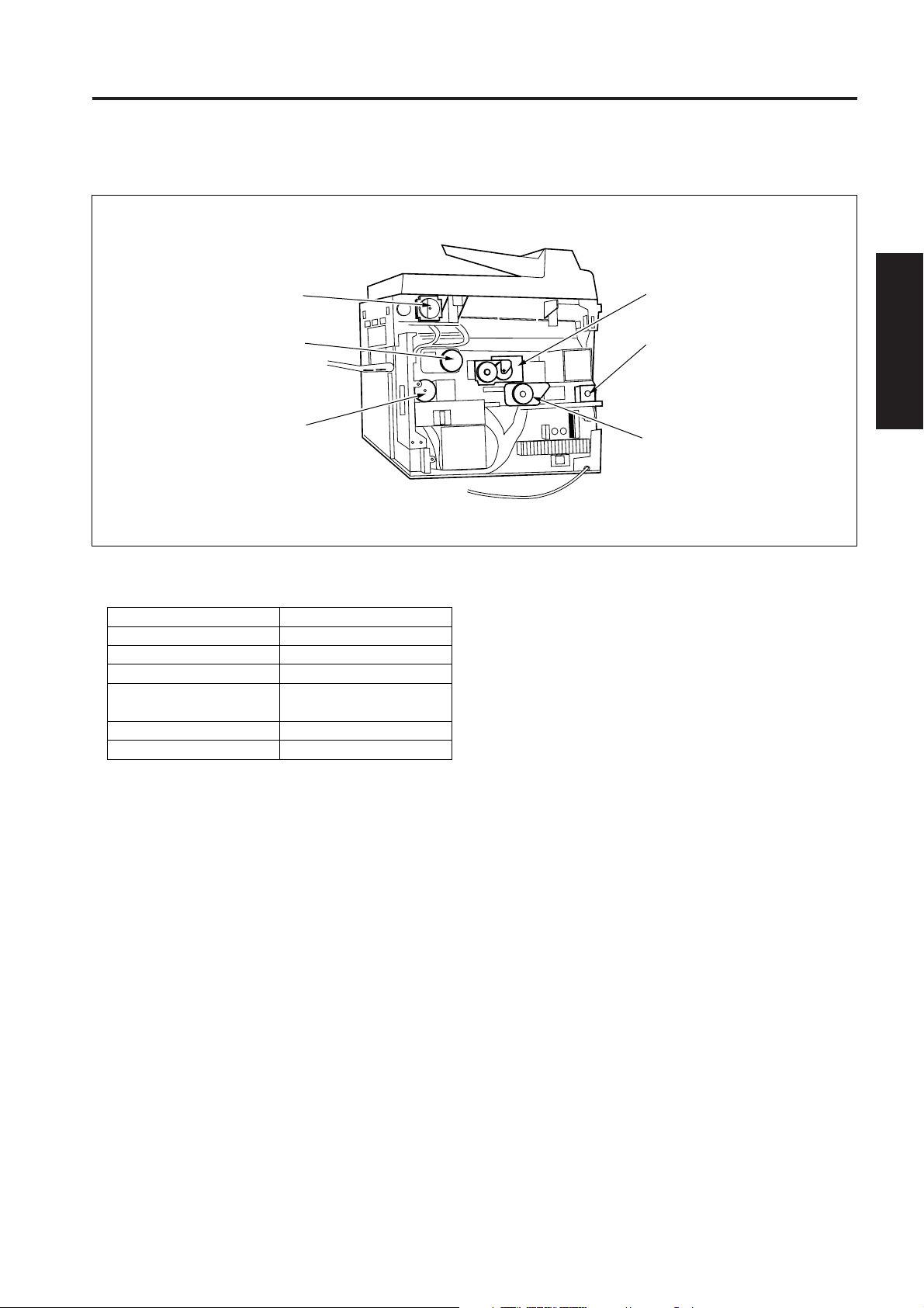
EXTERNAL SECTION
EXTERNAL SECTION
[1] Composition
Main power switch
Left side
cover
Paper exit cover
Sub power swicth
Operation panel
Front door
ADU
Tray 1
1 OUTLINE
RADF
Right side cover
Rear cover
2 UNIT EXPLANATION
By-pass
tray
Paper feed door
3 DIS./ASSEMBLY
2-A-1
Page 4

1 OUTLINE
2
2 UNIT EXPLANATION
3 DIS./ASSEMBLY
Blank page
Page 5
DRIVE SECTION
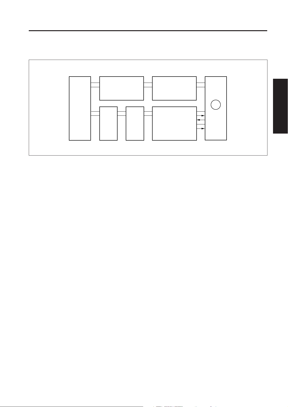
DRIVE SECTION
[1] Composition
Scanner motor
Developing motor
1st paper feed motor
[2] Mechanisms
Mechanisms
Drum drive *1
Developing drive *1
1st paper feed drive
2nd paper feed, conveyance and fixing drive
ADU drive
Reversal/paper exit drive
Methods
Gear drive
Gear drive
Timing belt + gear drive
Gear drive
Timing belt + gear drive
Timing belt + gear drive
1 OUTLINE
Drum motor
Reversal paper exit motor
2 UNIT EXPLANATION
Main motor
3 DIS./ASSEMBLY
*1: Separation of the different parts of the drive
system
The drum and developing agitator of this machine are
driven by separate motors in order to improve the
serviceability of the drum unit and also to improve the
developing performance.
2-B-1
Page 6

DRIVE SECTION
1 OUTLINE
[3] M1 (Main) Control
2
2 UNIT EXPLANATION
1. Operation
3 DIS./ASSEMBLY
5VDC
SGND
DCPS2
ICBCB
SCDB
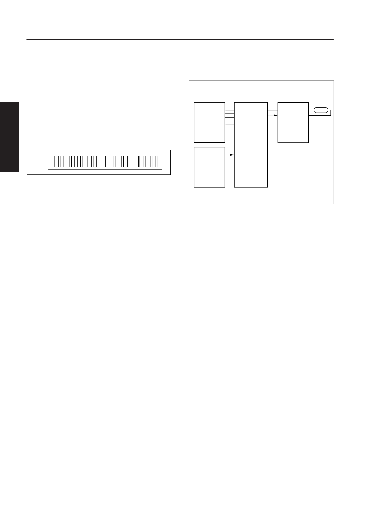
M1 (main) is controlled by the PRDB (printer drive
board).
M1 is a 24 V drive DC motor which drives the
conveyance section, 2nd paper feed section, fixing
section and conveyance belt. M1 is PLL-controlled
by feedback signals from a speed sensor installed
inside M1 itself, maintaining it at a constant speed.
M1 goes ON after the specified time from when the
Start print button is pressed, and goes OFF again
after the specified time from PS16 (registration)
going OFF at the final copy exit.
28VDC
PGND
DCPS1
5VDC
SGND
PRDB
24VDC
PGND
PGND
5VDC
CONT
LOCK SIG
SGND
M1 CLK
SGND
PS16 SIG
5VDC
M1
PS16
2. Signals
a. Input signals
(1) LOCK SIG (M1 to PRDB)
M1 rotational status detection signal
This signal becomes [L] when M1 reaches the set
speed.
(2) PS16 SIG (PS16 to PRDB)
Paper detection signal used for detecting the paper
feed temporary stop position.
PS16 goes ON and outputs [H] when paper is
detected at the paper feed temporary stop position.
b. Output signals
(1) CONT (PRDB to M1)
M1 drive control signal
[L]: M1 ON
[H]: M1 OFF
(2) M1 CLK (PRDB to M1)
Reference clock signal for controlling the speed of M1
2-B-2
Page 7
DRIVE SECTION
[4] M4 (Drum) Control
5VDC
SGND
DCPS2
ICBCB
M4 (drum) is controlled by the PRDB (printer drive board).
1. Operation
M4 is a 24 V drive DC motor which drives the drum,
toner conveyance screw, toner recycle screw and
separation claw swing section.
M4 is PLL-controlled by feedback signal from a
speed sensor installed inside M4 itself, maintaining it
at a constant speed.
M4 goes ON when the Start button is pressed, and
goes OFF again when the final copy has been exited.
SCDB
28VDC
PGND
DCPS1
5VDC
SGND
PRDB
24VDC
PGND
M4
5VDC
CONT
LOCK SIG
SGND
M4 CLK
2. Signals
a. Input signal
(1) LOCK SIG (M4 to PRDB)
M4 rotational status detection signal
This signal becomes [L] when M4 reaches the set
speed.
b. Output signals
(1) CONT (PRDB to M4)
M4 drive control signal
[L]: M4 ON
[H]: M4 OFF
1 OUTLINE
2 UNIT EXPLANATION
3 DIS./ASSEMBLY
(2) M4 CLK (PRDB to M4)
Reference clock signal for controlling the speed of M4
2-B-3
Page 8

1 OUTLINE
2
2 UNIT EXPLANATION
3 DIS./ASSEMBLY
Blank page
Page 9
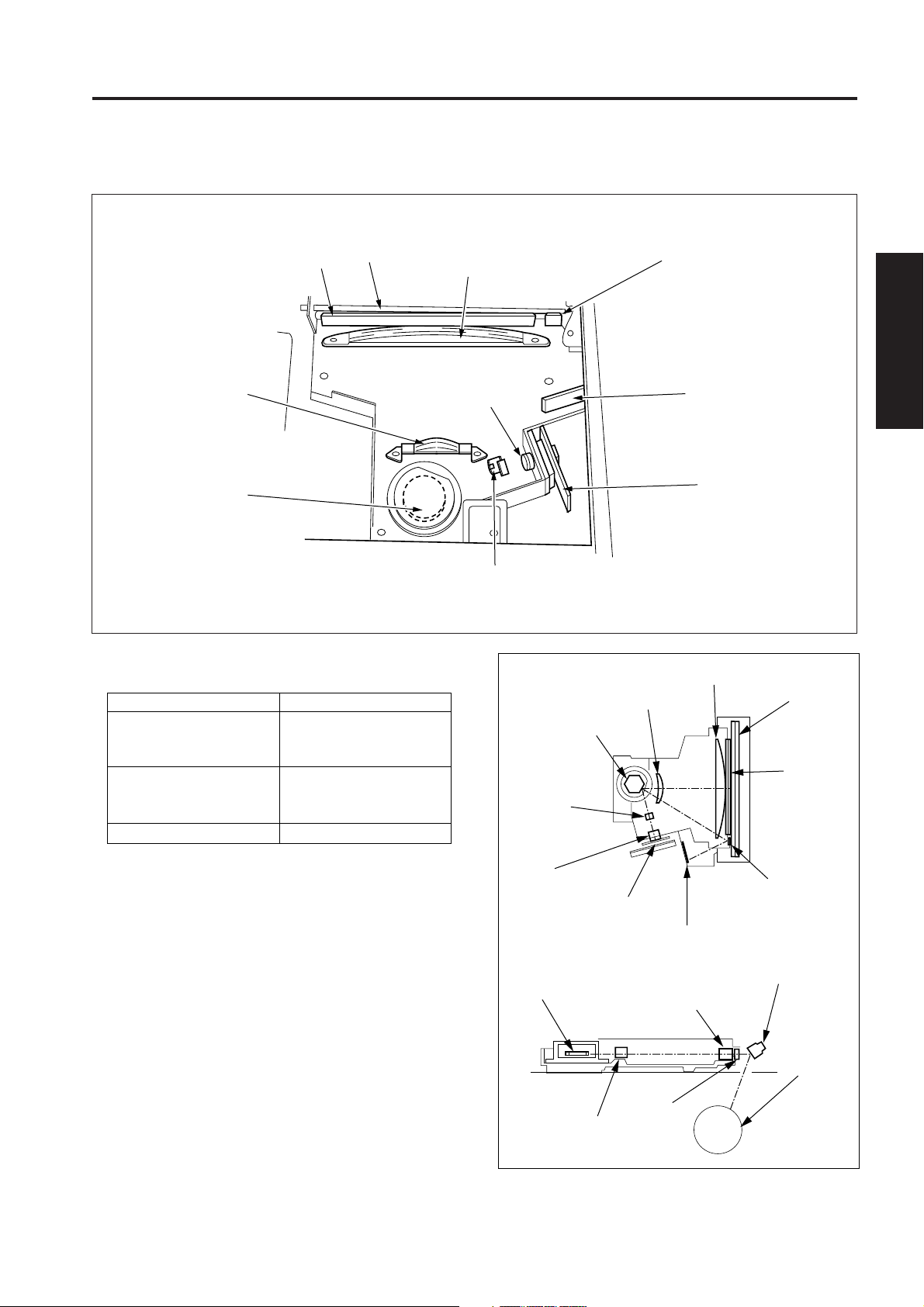
READ SECTION
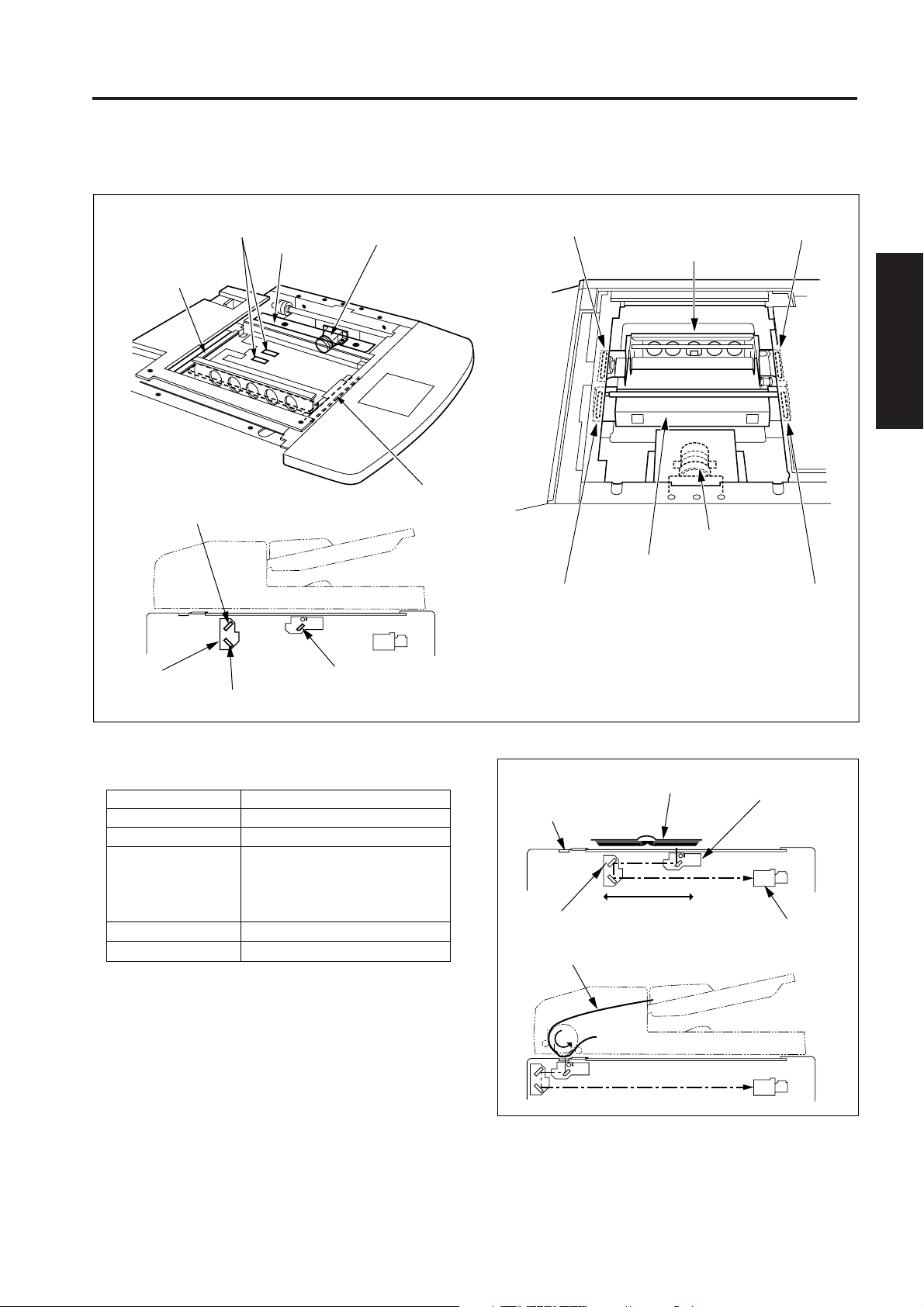
READ SECTION
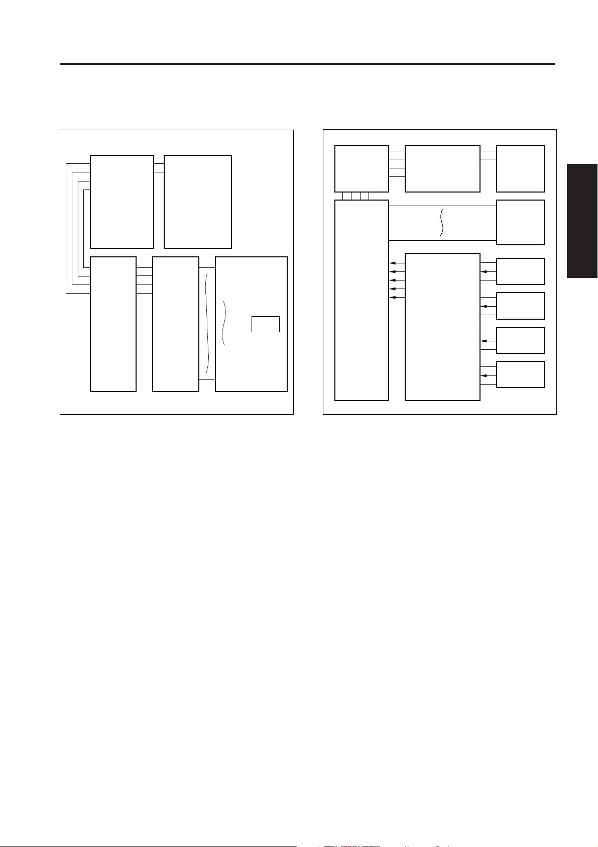
[1] Composition
APS 1 sensor
APS 2 sensor
Optics rail (rear)
2nd mirror
Exposure unit
CCD unit
Optics rail (front)
Optics driven sheet (lower)
Exposure unit
Optics driven sheet
(upper)
Optics driven sheet (lower)
V-mirror unit
CCD unit
Optics driven
sheet (upper)
1 OUTLINE
2 UNIT EXPLANATION
3 DIS./ASSEMBLY
V-mirror unit
3rd mirror
1st mirror
[2] Mechanisms
Mechanisms
Light source
Exposure
Scanning *1
Xenon lamp
Slit exposure
Platen original scanning:
1st, 2nd and 3rd mirror shift
RADF original scanning:
Fixed light source / Original moving
Lamp power supply
Cooling of optics
Lamp cord
Cooling of intake air using a fan
*1: Platen original scanning and RADF original
scanning
a. An original on the original glass is read while
moving the exposure unit and V mirror unit.
b. When reading a RADF original, the exposure unit
and V mirror unit shift to under the original glass (1).
Original reading takes place with the original
passing over the stationary exposure unit.
Methods
Original glass (1)
V-mirror unit
RADF original
Platen original
Exposure unit
CCD unit
2-C-1
Page 10
READ SECTION
1 OUTLINE
2
2 UNIT EXPLANATION
3 DIS./ASSEMBLY
[3] M2 (Scanner) Control
5VDC
5VDC
SGND
SGND
CB
DCPS2
ICB
28VDC
PGND
DCPS1
SCDB
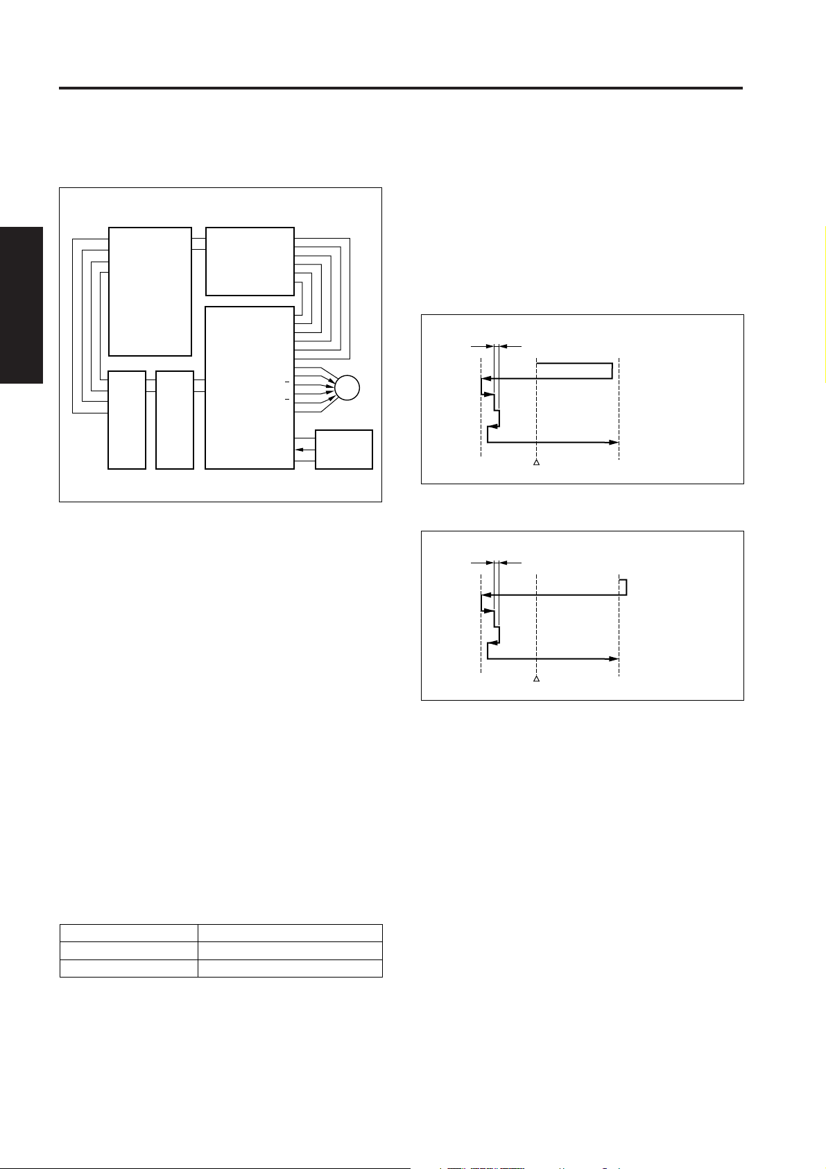
M2 (scanner) is driven by the SCDB (scanner drive board),
and is controlled by the ICB (image control board).
Related signal is PS3 (optics HP).
1. Operation
a. Operation of M2
M2 is a stepping motor which drives the exposure
unit. It rotates in the forward or reverse direction and
also changes speed according to the particular
scanning control operation.
The position of the exposure unit is controlled and
monitored by PS3 alone. The drive period and
direction of rotation of M2 are controlled by the
number of count pulses from when PS3 goes ON or
OFF.
The ICB continuously monitor the state of motion of
M2. It acquires the control timing related to paper
feed from the number of drive count pulses.
The ICB continuously monitors the motion of M2. It
acquires the control timing related to paper feed from
the number of drive count pulses.
b. Scanning speed of the exposure unit
Scanning speed
Magnification
Forward
Return
210 mm/sec (1:1)
862 mm/sec (Max.)
PGND
PGND
24VDC
24VDC
28VDC
PGND
24VDC
A
A
B
B
24VDC
SGND
OPT HOME
5VDC
Scanning speed
M2
PS3
c. Initial operation when power is turned ON
When SW2 (sub power) is turned ON, the exposure
unit performs a home position search. The home
position search operation differs depending upon
whether PS3 is ON or OFF. After the home position
search, the exposure unit waits in the platen mode
APS read position.
(1) When PS3 is ON
Shading correction read position
Platen APS read
position
Reference point
PS3
(2) When PS3 is OFF
Shading correction read position
Platen APS read
position
Reference point
d. Shading correction read operation
The white reference plate is glued at the back of the
original glass and the shading correction is carried out
when the SW2 is turned on and every scanning job.
e. Exposure scan mode
There are two exposure scanning modes, a platen
mode and a DF mode.
In the platen mode, the exposure unit scans and
reads the original in the same way as in a
conventional copying machine. In the DF mode,
however, the exposure unit remains fixed in the
specified position, and instead the RADF conveys the
original, causing it to be read.
PS3
2-C-2
Page 11
READ SECTION
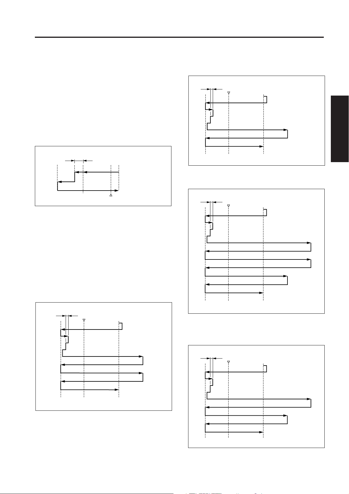
f. Scanning operation during DF mode
The read position in the DF mode is on the paper exit
side of PS3 (optics HP). While the exposure unit is
moving from the standby position (platen APS read
position) to the DF read position, the shading
correction read operation takes place.
Upon reaching the DF read position, the exposure
unit remains there until the original has been read,
upon completion of reading, then once again moves
to the platen APS read position and goes into a
standby status.
DF original
read position
Shading correction read position
Platen APS read
position
Reference
point
PS3
g. Scanning operation during platen copy mode
In the platen mode, the motion of the exposure unit
differs depending upon whether the copy density
mode is set to AE or Manual. In both cases, a
shading correction read operation takes place before
the exposure scanning operation starts. After
completion of the exposure scanning, then the
exposure unit moves to the APS read position and
goes into a standby status.
(2) When manual density has been selected
Shading correction read position
PS3
Exposure scan
Platen APS read position
Reference point
(3) Booklet mode (Output 1 to N, AE mode)
Shading correction read position
PS3
AE scan
Exposure scan (rear half)
Exposure scan (front half)
1 OUTLINE
2 UNIT EXPLANATION
3 DIS./ASSEMBLY
(1) AE mode
Shading correction read position
PS3
Reference point
AE scan
Exposure scan
Platen APS read
position
Platen APS read position
Reference point
(4) Booklet mode (Output 1 to N, When manual
density has been selected)
Shading correction read position
PS3
Exposure scan (rear half)
Exposure scan (front half)
Platen APS read position
Reference point
2-C-3
Page 12
1 OUTLINE
2
READ SECTION
2. Signals
a. Input signal
(1) OPT HOME (PS3 to SCDB to ICB)
Exposure unit home position detection signal
[L]: Exposure unit is in the home position.
[H]: Exposure unit is not in the home position.
b. Output signal
(1) A, A, B, B (SCDB to M2)
M2 (scanner) ON/OFF drive signal
[4] Exposure Control
PGND
LAMP ON/OFF
24VDC
DCPS1
28VDC
PGND
24VDC
24VDC
PGND
PGND
L1 INVB
LV
L1
HV
2 UNIT EXPLANATION
3 DIS./ASSEMBLY
24V
0V
L1 CONT
ICB
SCDB
Power is supplied to L1 (exposure lamp) from the L1 INVB
(L1 inverter) and is controlled by the ICB (image control
board) via the SCDB (scanner drive board).
1. Operation
L1 is a xenon lamp which is driven by an inverter
circuit.
A xenon lamp provides a stable light intensity and
also generates relatively little heat, hence it does not
require a light intensity control circuit that is used in
conventional copying machines, and also protective
control that is normally required due to heat
generation from the lamp is no longer used.
2. Signals
a. Output signal
(1) LAMP ON/OFF (ICB to SCDB to L1 INVB)
L1 ON/OFF control signal
[L]: L1 ON
[H]: L1 OFF
2-C-4
Page 13
READ SECTION
[5] Original Read Control
5VDC
SGND
12VDC
SGND
DCPS2
CB
28VDC
PGND
DCPS1
ICB
GND
SD0
SD1
/SEN
RCK
GND
TCK
GND
CCD
ADB
[6] APS Control
CB DCPS2 DCPS1
ICB
5VDC
SGND
12VDC
SGND
PS3
PS25
PS26
PS4
APS BOOK
SCDB
SGND
OPT HOME
5VDC
5VDC
APS TIMING
SGND
SGND
APS DATA2
5VDC
SGND
APS DATA3
5VDC
28VDC
PGND
ADB
PS3
PS4
PS25
PS26
1 OUTLINE
2 UNIT EXPLANATION
3 DIS./ASSEMBLY
The original is read by the CCD sensor installed on
the ADB (A/D converter board).
1. Operation
The light from the exposure lamp reflects back from
the original, passes through a lens, and hits the CCD
sensor. The CCD sensor generates an anolog
electrical signal corresponding to the light intensity.
The ADB then converts this signal into a digital
signal.
a. Original read operation
The original read timing is as follows.
(1) During a platen copy operation
PS3 (optics HP) goes OFF after the specified time
from when the Start button is pressed, and then the
exposure unit moves 2 mm to the paper feed side.
(2) During a DF copy operation
After the specified time from the ON of PS308
(original feed detect) by original leading edge.
APS takes place as a result of the signals read by the
APS sensors and CCD sensor being sent to the ICB
(image control board) when the RADF is opened and
closed.
Related signals are PS3, PS4 (APS timing) and PS301
(DF open/close detect).
1. Operation
a. APS detection operation
The APS detection operation differs depending upon
whether the platen mode or DF mode is used.
(1) During a DF copy operation
An original size is detected by ON or OFF of PS302
(original size detect 1) and PS303 (original size detect
2) on the paper feed tray of RADF, and resistance
value of VR301 (original size detect).
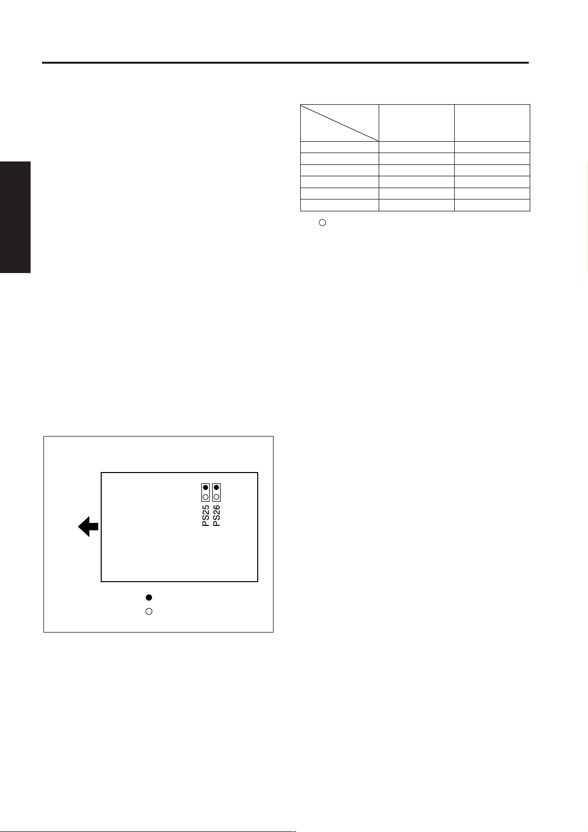
(2) During a platen copy operation
APS detection is used to detect the original size. This
is done by combining the ON/OFF signals from PS25
(APS 1) and PS26 (APS 2) with the detection signal
from the CCD sensor mounted on ADB.
2-C-5
Page 14
READ SECTION
1 OUTLINE
2
2 UNIT EXPLANATION
3 DIS./ASSEMBLY
PS25 (APS 1) and PS26 (APS 2) detect the original
size in the sub-scanning direction, and the CCD
sensor detects the original size in the main scanning
direction.
During APS detection, when L1 (exposure lamp)
lights, gradations of light intensity occur in the main
scanning direction due to the presence of an original.
The CCD sensor detects these gradations of light
intensity along one line, and the ICB (image control
board) judges the size of the original in the main
scanning direction from the positional relationship
between the two points where the light intensity level
switches from black generated by a sky shot to white
generated by the edge of the original.
Close RADF, then detection of the original size in the
main scanning direction takes place once again at
the instant PS301 (DF open/close detect) goes ON,
and the original size is confirmed.
PS25 and PS26 each consist of an LED and a
photosensor. Light emitted from each LED is
reflected off the original, and received by the
photosensor, thus enabling the size of the original to
be detected.
The PS25 and PS26 consist of LEDs and
photosensors. APS detection takes place as a result
of the light emitted from each LED being reflected off
the original and received by the photosensor.
Sensor
Paper size
A3
B4
A4R
B5R
A4
B5
: Paper is detected (ON).
✕ : Paper is not detected (OFF).
b. APS detection timing
The APS detection timing differs depending upon
whether the platen mode or the DF mode is used.
(1) During a DF copy operation
When either the DF mode is selected or an original is
placed in the RADF paper feed tray, the original size
is detected by PS302 (original size detect 1), PS303
(original size detect 2) and VR301 (original size
detect).
(2) During a platen copy operation
• When PS4 (APS timing) is ON and PS301 is ON
• If RADF is open, the original size is detected when
the Start button is pressed.
PS302
PS25
●
●
●
×
×
×
PS303
PS26
●
●
×
×
×
×
Paper exit side
: Photosensor
: LED
The relation between each sensor and the paper size
is shown below.
2-C-6
Page 15

READ SECTION
ICB
ADB
GND
SD0
SD1
/SEN
RCK
GND
TCK
GND
CB
CCD
28VDC
PGND
DCPS1
5VDC
SGND
12VDC
SGND
DCPS2
2. Signals
a. Input signals
(1) OPT HOME (PS3 to SCDB to ICB)
Exposure unit home position detection signal
[L]: Exposure unit is in the home position.
[H]: Exposure unit is not in the home position.
(2) APS TIMING (PS4 to SCDB to ICB)
RADF opening/closing detection signal
Activates or deactivates the APS function at a platen
copy operation.
[L]: OFF (APS function deactivated)
[H]: ON (APS function activated)
(3) APS DATA 2 (PS25 to SCDB to ICB)
Paper size detection signal
[L]: Paper is detected.
[H]: Paper is not detected.
(4) APS DATA 3 (PS26 to SCDB to ICB)
Paper size detection signal
[L]: Paper is detected.
[H]: Paper is not detected.
[7] AE Control
1 OUTLINE
2 UNIT EXPLANATION
3 DIS./ASSEMBLY
When an AE scanning takes place, the CCD sensor
installed on the ADB (A/D converter board) reads the
original density, and the ICB (image control board)
performs processing corresponding to the read
results and selects the optimum γ correction curve for
the original reproduction. This operation is called AE
control. The selection of this γ correction curve is
done by the CPU on the ICB.
2-C-7
Page 16

1 OUTLINE
2
2 UNIT EXPLANATION
READ SECTION
1. Operation
a. AE detection operation
(1) During a platen copy operation
When the Start button is pressed, an AE scanning
takes place, and the density of the original is read
over the following range.
<AE sampling range>
1) When RADF is open
Range of non-image area erace mode, or the
inside of the area detected by the APS
2) When RADF is closed
• Range of 20 mm inward of the original size
detected by the APS
• If the original size cannot be determined by the
APS, a range of 20 mm inward of the minimum
original size set for the particular shipping
destination of the machine.
(2) During a DF copy operation
The image at the leading edge of the original is read
3 DIS./ASSEMBLY
by the original feed operation that takes place when
the Start button is pressed, and the read data is used
to perform density measurement.
<AE sampling range>
1) Main scanning direction
• A range of 20 mm inward of the original size
detected by the APS
• If the original size cannot be determined by the
APS, a range of 20 mm inward of the minimum
original size set for the particular shipping
destination of the machine.
2) Sub scanning direction
Range between 1.5 mm and 2.9 mm from the
leading edge of the original
2-C-8
Page 17
WRITE UNIT
WRITE UNIT
[1] Composition
fθ lens
Polygon mirror
Dust-proof glass
Write mirror
Cylindrical lens 2
Collimator lens unit
Cylindrical lens 1
1 OUTLINE
Index mirror
Index sensor board
2 UNIT EXPLANATION
Laser drive board
3 DIS./ASSEMBLY
[2] Mechanisms
Mechanisms Methods
Scan *1 Polygon mirror
Rotational speed:
· 49606.3 rpm
Light source Laser diode (1)
· Output : Max. 5 mW
· Wavelength : 780 nm
Positioning Index sensor
*1: Path of laser beam
The light output from the semiconductor laser is sent
to the OPC drum via the collimator lens, cylindrical
lens 1, polygon mirror, f
write mirror.
θ
lens, cylindrical lens 2, and
Polygon mirror
Cylindrical
lens 1
Collimator lens unit
Polygon mirror
fθ lens
fθ lens
Laser diode
Cylindrical lens 2
Dust-proof
glass
Cylindrical lens 2
Write mirror
Dust-proof
glass
Index mirror
Index sensor board
Write mirror
OPC drum
2-D-1
Page 18
WRITE UNIT
1 OUTLINE
2
2 UNIT EXPLANATION
3 DIS./ASSEMBLY
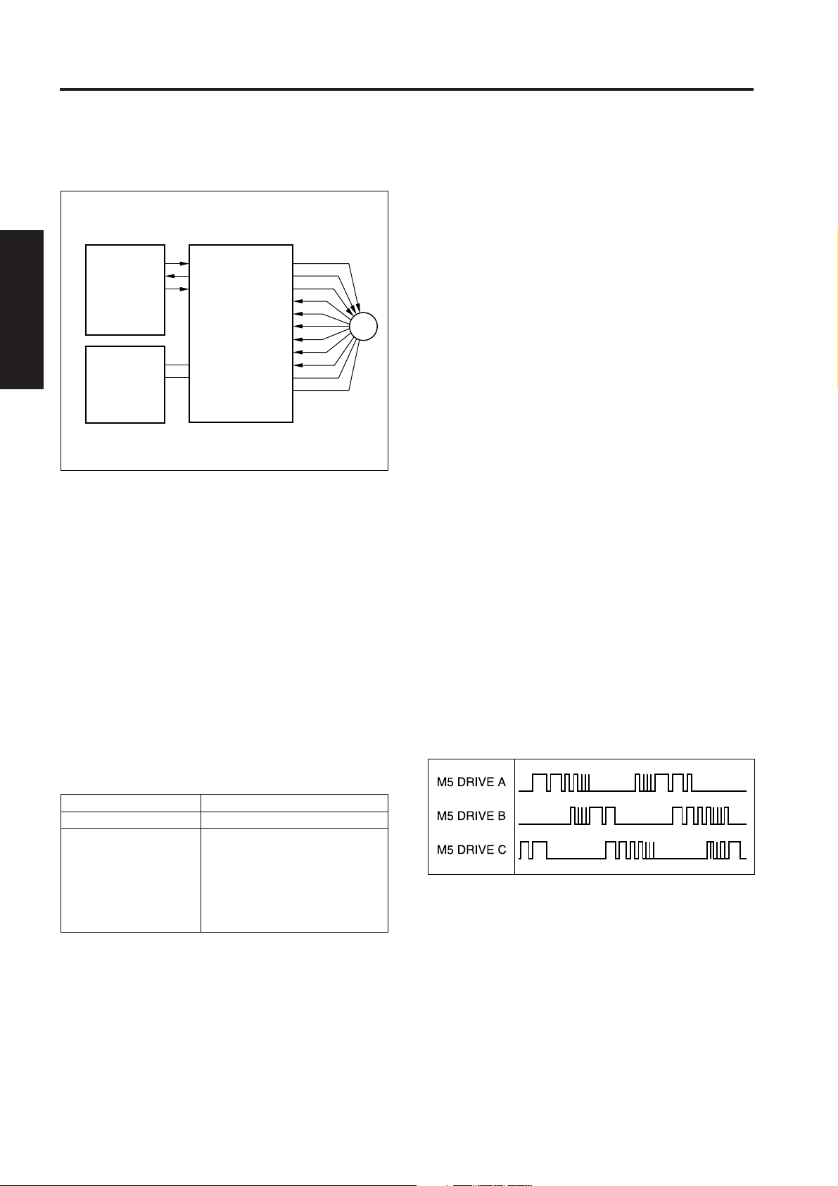
[3] M5 (Polygon) Control
POLY CONT
POLY PLL LOCK
POLY CLK
SCDB
24VDC
PGND
DCPS1
M5 (polygon) is driven by the PMDB (Polygon motor
drive board), and is controlled by the SCDB (scanner
drive board).
1. Operation
a. M5 is a 3-phase brushless DC motor which is driven
using a 3-phase bipolar method. The current flowing
through the windings is switched according to the
position of the rotor which is detected by a sensor
(magnetic sensor) inside the motor.
This motor rotates the polygon mirror, causing the
laser beam from LDB (lazer drive board) to be
scanned in the axial direction of the drum. The
speed of the motor is maintained constant by PLL
control.
b. M5 is powered by 24 VDC. The rotational speed is
as follows.
PMDB
M5 DRIVE A
M5 DRIVE B
M5 DRIVE C
M5 MAG C
M5 MAG C'
M5 MAG B
M5 MAG B'
M5 MAG A
M5 MAG A'
12VDC
SGND
M5
2. Signals
a. Input signals
(1) POLY PULL LOCK (PMDB to SCDB)
M5 rotation speed monitoring signal
[L]: Normal rotation
[H]: Stop or rotation abnormality
(2) M5 MAG A/A' (M5 to PMDB)
M5 MAG B/B' (M5 to PMDB)
M5 MAG C/C' (M5 to PMDB)
These are output signals from the position sensors
(magnetic sensors) installed inside M5. The PMDB
detects the position of the rotor of the motor by
means of these signals, and switches over the M5
DRIVE A to C output.
b. Output signals
(1) POLY CONT (SCDB to PMDB)
This signal controls the ON/OFF state of M5.
[L]: M5 ON
[H]: M5 OFF
(2) POLY CLK (SCDB to PMDB)
This is a reference clock signal for PLL-controlling M5
in the PMDB.
(3) M5 DRIVE A to C (PMDB to M5)
This is the drive output signal for M5. While M5 is
rotating, voltages are output sequentially from M5
DRIVE A to C, and applied to M5.
The voltage from each output that is applied to M5
consists of the pulses shown below. The pulse width
of this output changes according to the rotation
condition of M5, as shown in the figure, and as a
result the RMS value of the voltage applied to M5
changes, causing the speed to be regulated.
State of the machine
During copy
Rotational speed
49606.3 rpm
One of the following three
speeds can be selected
During idling
using the “25” mode.
• 49606.3 rpm
• 25000 rpm *
• Stop *
* If the item marked * is selected, the rotational
speed of M5 switches over after the lapse of the
specified time from the completion of the warm-up
or the end of the copy process.
The specified time can be selected using the “25”
mode among below.
· 15 sec, 30 sec, 60 sec, 120 sec
2-D-2
Page 19
WRITE UNIT
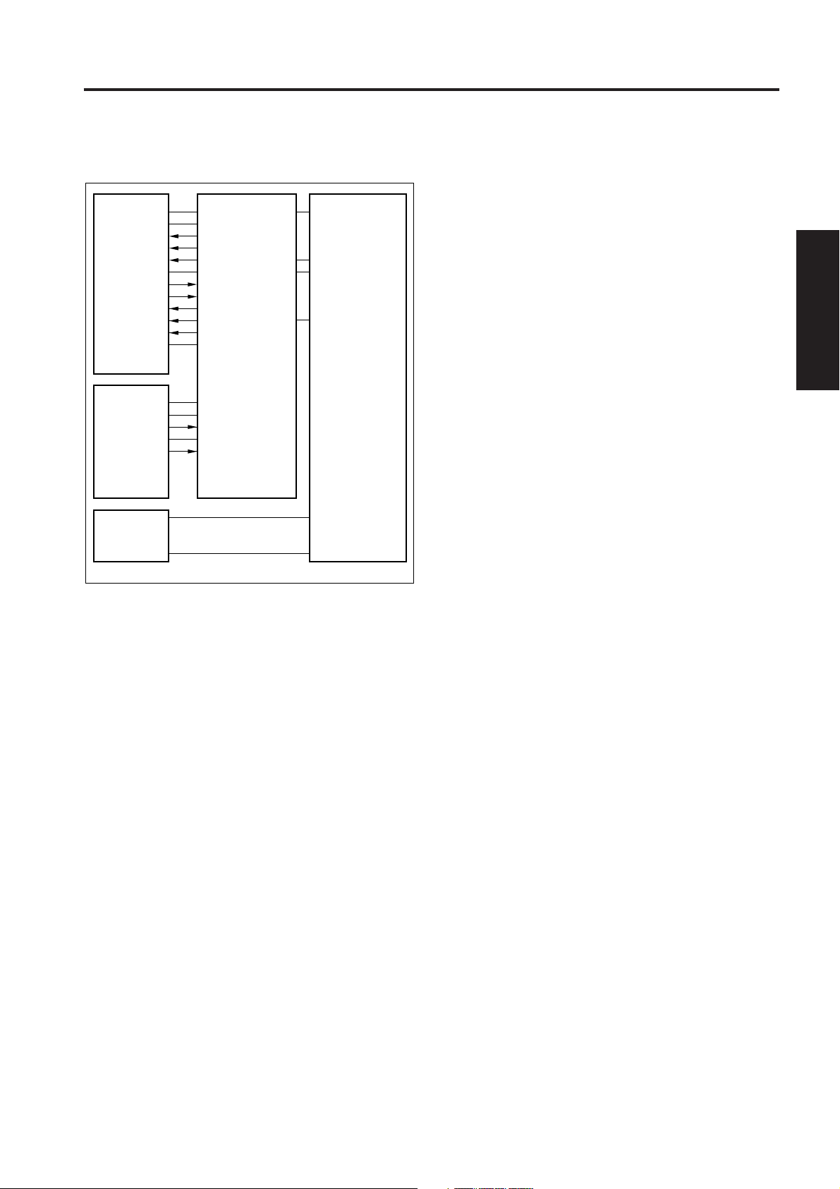
[4] Image Write Control
5VDC
SGND
/S/H
/ENB
/VIDEO
VIDEO
/ALM
N.C.
DACLK
DI
LD
5VDC
LDB
5VDC
SGND
/INX
SGND
IDPR 5VDC
INDEXSB
ADB
The analog image data from the CCD sensor is A/Dconverted and processed by the ADB (A/D converter
board). The processed image data is memorized by the CB
(control board), then returned to the ICB (image control
board) once again and converted into a laser record signal.
The laser record signal is transmitted via the CB to the LDB
(Laser drive board) by the control signal from the ICB, and
output as an optical signal from the laser installed on the
LDB. The write start position of the laser record signal is
detected by INDEXSB (index sensor board).
1. Operation
a. Image processing
The following processing is carried out by the ICB.
(1) AOC (Automatic Offset Correction)
IC on ADB automatically adjusts analog off set
voltage of CCD sensor output.
CB
ICB
(3) Shading correction
<Implementation timing>
White correction, Black correction
• When SW2 is ON
• Before job
(4) Brightness/density conversion
(5) AE processing
(6) Text/dot pattern judgement
(7) Filtering
(8) Magnification change processing
(9) Copy γ correction
(10) Write density control
b. Write
The ICB sends image data one pixel at a time to LDB
in accordance with control signals from the CB.
LDB cause the laser to emit at a time period
corresponding to the image data. This laser light is
applied to the drum.
(1) MPC (Maximum Power Control)
The ICB instructs the LDB to cause the laser to
output the maximum power output value, thus setting
the maximum output value. The LDB stores this
setting, and maintains the laser light intensity stored
by means of the APC (Automatic Power Control)
operation.
<MPC timing>
• When SW2 is turned ON.
(2) APC (Automatic Power Control)
The ICB outputs an APC start instruction to the LDB
at the following timing, after MPC is set.
<APC timing>
• When PLL lock of M5 (polygon) is detected.
After PLL lock is detected, the LDB automatically
monitors the laser drive current one line at a time,
and controls it so that the light intensity remains the
MPC value.
(3) Write Timing
In this machine, the INX signal from INDEXSB
determines the laser write start timing for each scan
in the axial direction of the drum.
1 OUTLINE
2 UNIT EXPLANATION
3 DIS./ASSEMBLY
(2) AGC (Automatic Gain Correction)
When SW2 (sub power) is turned ON, the white
reference plate is read, and the amplification of the
analog output from the CCD sensor is automatically
adjusted so that the resulting level is the upper limit of
the A/D converter.
2-D-3
Page 20

1 OUTLINE
2
2 UNIT EXPLANATION
WRITE UNIT
2. Signals
a. Input signals
(1) INX (INDEXSB to CB to ICB)
Write system index signal
(2) IDPR (INDEXSB to CB to ICB)
5 VDC power monitoring signal for INDEXSB (index
sensor board)
(3) ALM (LDB to CB to ICB)
Signal which indicates an abnormality in the laser
drive current (APC operation).
[L]: Abnormal
[H]: Normal
b. Output signals
(1) VIDEO (ICB to CB to LDB)
Laser image data signal
(2) DA CLK (ICB to CB to LDB)
Data transfer clock signal for MPC setting value
(3) DI (ICB to CB to LDB)
Data signal of MPC setting value
(4) LD (ICB to CB to LDB)
3 DIS./ASSEMBLY
Storage directive signal for MPC setting value
(5) S/H (ICB to CB to LDB)
APC sampling signal for one line scan
(6) ENB (ICB to CB to LDB)
Laser APC function ON/OFF control signal
While this signal is OFF then the laser beam output is
prohibited.
2-D-4
Page 21
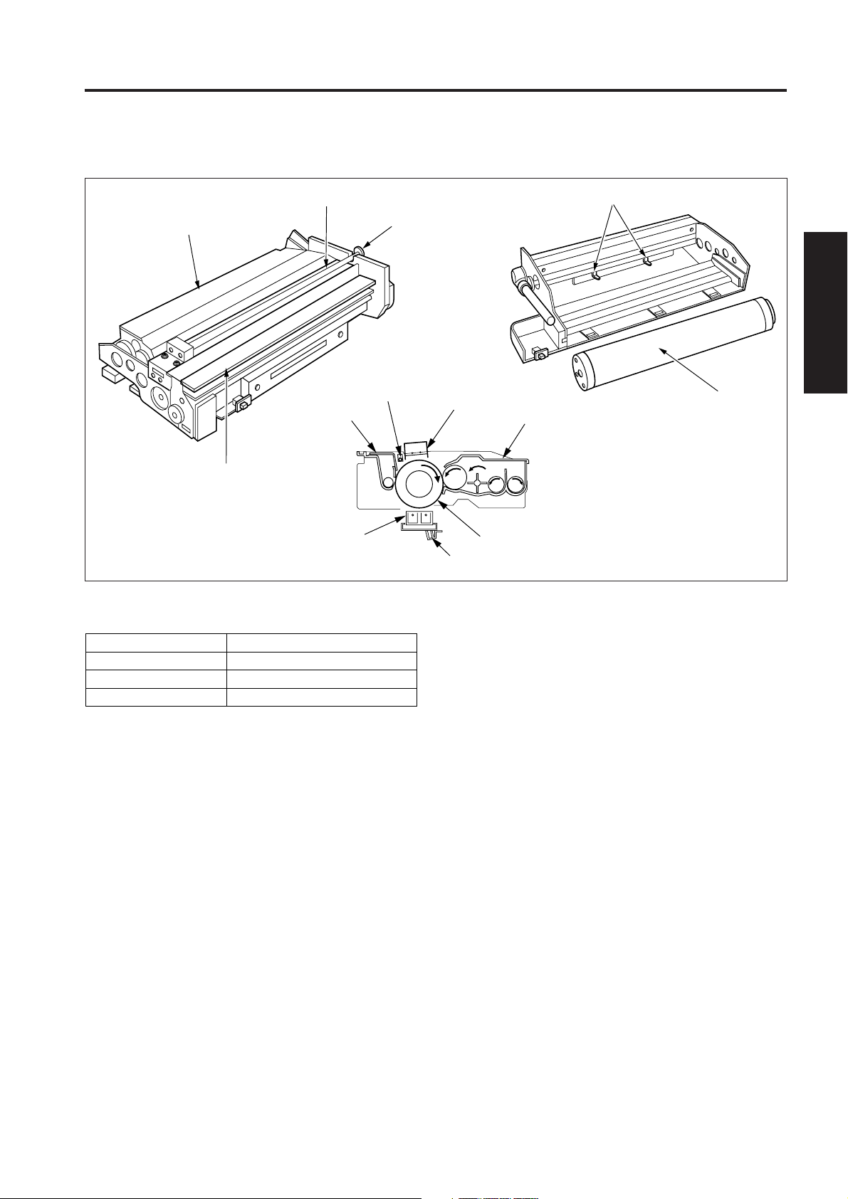
DRUM UNIT
DRUM UNIT
[1] Composition
Developing unit
Cleaning unit
Charging corona unit
Cleaning unit
Transfer/separation
corona unit
Charge cleaning knob
PCL
Charging corona unit
TSL
1 OUTLINE
Separation claws
2 UNIT EXPLANATION
Drum
Developing unit
Drum
3 DIS./ASSEMBLY
[2] Mechanisms
Mechanisms
Carriage support
PCL
Auxiliary separation
The drum unit of this machine is an integral assembly
consisting of the drum, and also the charging corona unit,
developing unit, cleaning unit, toner recycle unit and the
PCL which are installed around the drum.
Methods
Fixed rail
LED
Separation claws
2-E-1
Page 22

DRUM UNIT
1 OUTLINE
[3] PCL/TSL Control
[4] Separation Claw Control
2
PRDB
24VDC
PCL CONT
24VDC
TSL DRIVE
24VDC
MC1 DRIVE
SGND
PS16 SIG
5VDC
PCL
TSL
MC1
PS16
24VDC
PGND
2 UNIT EXPLANATION
DCPS1
The PCL (pre-charging lamp) and TSL (transfer
synchronization lamp) consist of LEDs which are
controlled by the PRDB (printer drive board).
3 DIS./ASSEMBLY
1. Operation
PCL goes ON after the specified time from when the
Start print button is pressed, and goes OFF again
after the specified time from the turning OFF of PS16
(registration) upon the final copy exit.
TSL goes ON after the specified time from when MC1
(registration) goes ON, and goes OFF again after the
specified time from PS16 going OFF.
2. Signals
a. Output signals
(1) PCL CONT (PRDB to PCL)
PCL ON/OFF control signal
[L]: PCL ON
[H]: PCL OFF
MC1 DRIVE
PRDB
24VDC
SD1 DRIVE
24VDC
SD1
MC1
24VDC
PGND
DCPS1
The separation claws are driven by SD1 (separation claw),
and is controlled by the PRDB.
1. Operation
SD1 goes ON after the specified time from when MC1
goes ON, causing the separation claws to touch the
drum in order to help separate the paper from the drum.
2. Signals
a. Output signal
(1) SD1 DRIVE (PRDB to SD1)
SD1 drive control signal
[L]: SD1 ON
[H]: SD1 OFF
(2) TSL DRIVE (PRDB to TSL)
TSL drive control signal
[L]: TSL ON
[H]: TSL OFF
(3) MC1 DRIVE (PRDB to MC1)
MC1 drive control signal
[L]: MC1 ON
[H]: MC1 OFF
2-E-2
Page 23

DRUM UNIT
[5] Transfer Entrance Guide Plate Control
DCPS1
SCDB
24VDC
PGND
PGND
24VDC
PGND
24VDC
PGND
5VDC
SGND
28VDC
PGND
DCPS2
CB
ICB
A constant voltage is applied to the transfer guide plate in
order to prevent toner from adhering to it.
SGND
5VDC
PRDB
5VDC
CONT
LOCK SIG
SGND
M1 CLK
GP CONT
SGND
PS16 SIG
5VDC
1 OUTLINE
M1
GP
GP
2 UNIT EXPLANATION
HV2
PS16
3 DIS./ASSEMBLY
1. Operation
a. ON/OFF timing
Transfer guide plate control goes ON after the
specified time from when the Start button is pressed,
and goes OFF again after the specified time from
PS16 (registration) goes OFF.
b. Applied voltage
–500 VDC
2. Signals
a. Output signals
(1) GP CONT (PRDB to HV2)
Signal for controlling ON/OFF of the voltage applied
to the paper transfer guide plate.
[L]: Voltage is applied.
[H]: Voltage is not applied.
2-E-3
Page 24

1 OUTLINE
2
2 UNIT EXPLANATION
3 DIS./ASSEMBLY
Blank page
Page 25

CORONA UNIT SECTION
CORONA UNIT SECTION
[1] Composition
<Charging corona unit> <Transfer and separation corona unit>
Charging wire cleaning block
PCL
Transfer wire
Charging control plate
Charging
wires
Separation wire
Spark arrestor plate (rear)
Spark arrestor plate (front)
Plunging prevention plate
1 OUTLINE
2 UNIT EXPLANATION
3 DIS./ASSEMBLY
[2] Mechanisms
Mechanisms
Charging
Transfer
Separation
Scorotron (DC negative corona discharge)
Discharge wire: Tungsten 0.06 mm dia.
Grid control: Stainless steel plate
With manual wire cleaner
DC positive corona discharge
Discharge wires: Tungsten 0.06 mm dia.
(protection by a tough film of oxide)
AC/DC corona discharge
Discharge wires: Tungsten 0.06 mm dia.
(protection by a tough film of oxide)
Method
(gold-plated skin path)
2-F-1
Page 26

CORONA UNIT SECTION
1 OUTLINE
[3] Charging Control
2
5VDC
SGND
DCPS2
28VDC
PGND
DCPS1
2 UNIT EXPLANATION
CB
ICB
HV1 (high voltage unit/1), which controls charging,
operates by means of control signals from the PRDB
(printer drive board), and outputs a high voltage to the
3 DIS./ASSEMBLY
charging wires.
SCDB
1. Operation
Charging control goes ON after the specified time
from when M4 (drum) goes ON, and goes OFF again
after the specified time from PS16 (registration) going
OFF.
a. Charging
A Scorotron charging method is used. 24 VDC input
from the DCPS1 (DC power supply 1) is raised to a
negative DC high voltage which is then discharged.
b. Charging correction by means of the grid
voltage
The grid voltage is output from HV1 to the charging
control plate.
24VDC
PGND
24VDC
PGND
24VDC
PGND
5VDC
CONT
LOCK SIG
PGND
M4 CLK
C CONT
C SHIFT
SGND
5VDC
PRDB
G SHIFT
F(C) SIG
SGND
PS16 SIG
5VDC
2. Signals
a. Input signal
(1) F(C) SIG (HV1 to PRDB)
[L] is output when the spark detection circuit operates
and the charging output forcibly goes OFF.
b. Output signals
(1) C CONT (PRDB to HV1)
Charging and grid voltage ON/OFF control signal
[L]: Charging and grid voltage ON
[H]: Charging and grid voltage OFF
(2) C SHIFT (PRDB to HV1)
The charging corona unit output level is controlled by
means of analog signals from the PRDB.
C SHIFT output range 4 to 10 V
Charging output range –550 to –1200 µA
(3) G SHIFT (PRDB to HV1)
The charging grid voltage output level is controlled by
analog signals from the PRDB.
M4
CHARGING
GRID
HV1
PS16
2-F-2
G SHIFT output range 4 to 10 V
Grid voltage output range –500 to –900 V
Page 27

CORONA UNIT SECTION
T CONT
T SHIFT
S CONT
S(AC) SHIFT
S(DC) SHIFT
F(T) SIG
F(S) SIG
24VDC
MC1 DRIVE
SGND
PS16 SIG
5VDC
PRDB
PS16
28VDC
PGND
DCPS1
SCDB
5VDC
SGND
DCPS2
CB
ICB
24VDC
PGND
24VDC
PGND
SGND
5VDC
MC1
HV2
SEPARATION
TRANSFER
[4] Transfer/Separation Control
Transfer and separation corona unit are controlled by the
PRDB (printer drive board) and HV2 (high voltage unit/2).
1. Operation
Transfer and separation corona discharge go ON after
the specified time from when MC1 (registration) goes
ON, and goes OFF again after the specified time from
PS16 (registration) going OFF.
2. Signals
a. Input signals
(1) F(T) SIG (HV2 to PRDB)
[L] is output when the transfer spark detection circuit
operates.
(2) F(S) SIG (HV2 to PRDB)
[L] is output when the separation spark detection
circuit operates.
1 OUTLINE
2 UNIT EXPLANATION
3 DIS./ASSEMBLY
a. Transfer
A positive DC high voltage is used for transfer.
b. Separation
An AC high voltage is used for separation.
2-F-3
Page 28

1 OUTLINE
2
2 UNIT EXPLANATION
CORONA UNIT SECTION
b. Output signals
(1) T CONT (PRDB to HV2)
Transfer corona unit ON/OFF control signal.
When this signal is [L], the transfer corona unit goes
ON.
(2) T SHIFT (PRDB to HV2)
Transfer corona unit output level control signal
This signal controls the transfer corona unit output
level using analog signals from the PRDB (printer
drive board).
T SHIFT output range 4 to 10 V
Transfer voltage output range
(3) S CONT (PRDB to HV2)
Separation corona unit ON/OFF control signal
When this signal is [L], the separation corona unit
goes ON.
(4) S SHIFT (AC) (PRDB to HV2)
Separation corona unit output level control signal
This signal controls the separation corona unit output
level (AC component) using analog signals from the
PRDB.
40 to 450 µA
3 DIS./ASSEMBLY
S SHIFT (AC) output range 4 to 10 V
Separation AC voltage 2.8 to 5.5 kV
output range
(5) S SHIFT (DC) (PRDB to HV2)
Separation corona unit output level control signal
This signal controls the separation corona unit output
level (DC bias component) using analog signals from
the PRDB.
S SHIFT (DC) output range 4 to 10 V
Separation DC bias voltage 0 to –300 µA
output range
2-F-4
Page 29

DEVELOPING UNIT
DEVELOPING UNIT
[1] Composition
Developing sleeve
[2] Mechanisms
Developing unit cover
Developing regulating plate
Developing sleeve
1 OUTLINE
Agitator screws
2 UNIT EXPLANATION
Agitator wheel
3 DIS./ASSEMBLY
Mechanisms
Developing
Developing bias
Developer agitation
2-component developer
DC bias
Main agitation
Auxiliary agitation
Methods
1. Developing unit drive
The developing unit is driven by the developing motor
(M3).
The drive is transmitted from the developing drive
input gear (1) to the agitation section.
The drive is transmitted from the developing drive input
gear (2) via the developing MC (MC2) to the developing
sleeve. (Refer to the drive system diagram.)
2-G-1
Page 30

DEVELOPING UNIT
1 OUTLINE
[3] M3 (Developing) Control
2
2 UNIT EXPLANATION
3 DIS./ASSEMBLY
1. Operation
5VDC
SGND
CB
28VDC
PGND
DCPS2
ICB
PGND
PGND
24VDC
24VDC
PGND
DCPS1
SCDB
M3 (developing) is controlled by the PRDB (Printer
drive board).
M3 is a 24 V drive DC motor which drives the
developing sleeve, agitator wheel and agitator screw.
M3 is PLL-controlled by feedback signals from a
speed sensor installed inside M3 itself, maintaining it
at a constant speed.
M3 goes ON after the specified time from when the
Start button is pressed, and goes OFF again after the
specified time from the completion of charging
control.
MC2 (developing) goes ON after the specified time
from when M3 goes, and goes OFF again after the
specified time from PS16 (registration) going OFF
M3
PS16
MC2
SGND
5VDC
5VDC
SGND
CONT
CLK
MODE
LD
SGND
PS16 SIG
5VDC
24VDC
MC2 DRIVE
PRDB
2. Signals
a. Input signal
(1) LD (M3 to PRDB)
M3 rotational status detection signal
This signal becomes [L] when M3 reaches the set
speed.
b. Output signals
(1) CONT (PRDB to M3)
M3 drive control signal
[L]: M3 ON
[H]: M3 OFF
(2) CLK (PRDB to M3)
M3 rotational speed control reference clock signal
(3) MODE (PRDB to M3)
M3 rotational speed switching signal
[L]: High speed
[H]: Low speed
(4) MC2 DRIVE (PRDB to MC2)
MC2 drive control signal
[L]: MC2 ON
[H]: MC2 OFF
2-G-2
Page 31

DEVELOPING UNIT
5VDC
SGND
CONT
CLK
MODE
LD
24VDC
PGND
B CONT
B SHIFT
SGND
PS16 SIG
5VDC
PRDB
PS16
28VDC
PGND
DCPS1
SCDB
5VDC
SGND
DCPS2
CB
ICB
PGND
PGND
24VDC
24VDC
PGND
SGND
5VDC
HV2
M3
BIAS
[4] Developing Bias Control
The developing bias is controlled by the PRDB (printer
drive board) via the HV2 (high voltage unit/2).
1 OUTLINE
2 UNIT EXPLANATION
3 DIS./ASSEMBLY
1. Operation
The developing bias is applied to the sleeve after the
specified time from when the M3 (developing) goes
ON, and goes OFF again after the specified time from
PS16 (registration) going OFF
2. Signals
a. Output signals
(1) B CONT (PRDB to HV2)
Developing bias ON/OFF control signal
When this signal is [L], the developing bias goes ON,
and a high voltage is output.
(2) B SHIFT (PRDB to HV2)
Developing bias level control signal
This signal controls the output level of the developing
bias by means of analog signals from the PRDB.
B SHIFT output range 2 to 8 V
Bias voltage output range –400 to –700 VDC
2-G-3
Page 32

DEVELOPING UNIT
1 OUTLINE
[5] Toner Density Control
2
5VDC
SGND
12VDC
SGND
28VDC
PGND
DCPS2
2 UNIT EXPLANATION
CB
3 DIS./ASSEMBLY
The toner density is controlled by the TDS (toner density
sensor), M11 (toner supply 2) and the PRDB (printer drive
board).
ICB
1. Operation
a. Toner density detection
The TDS detects the density of the toner in the
developing unit using an L detection method, and
outputs an analog voltage signal that is proportion to
the density to the PRDB.
The PRDB compares the detected voltage with the
reference voltage corresponding to the initial density
of the developer, and judges the necessity of
supplying toner.
DCPS1
SCDB
PGND
PGND
24VDC
24VDC
PGND
12VDC
SGND
5VDC
PRDB
5VDC
SGND
CONT
CLK
MODE
LD
24V (A )
24V (A )
TDS CONT
12VDC
TONER ANG SIG
SGND
SGND
PS16 SIG
5VDC
24VDC
MC2 DRIVE
M3
M11
TDS
PS16
MC2
b. Toner supply operation to the developing unit
M11 is driven by 24 VDC supplied from the PRDB.
(1) When the power is switched ON
After the power is switched ON and the agitator
screw is driven by the M3 (developing) via the MC2
(developing), then after the specified time the toner
density is read.
This density is compared with the initial density of the
developer, and if the density is low, M11 goes ON
and toner supply takes place. (recovered until its
initial density)
(2) During a copy operation
The relationship between the TDS output voltage and
the toner supply time is as follows.
2-G-4
TDS output voltage
1.99 V or lower
2.00 to 2.09 V
2.10 to 2.17 V
2.18 to 2.27 V
2.28 to 2.34 V
2.35 to 2.42 V
2.43 V or higher
Toner supply time
0 sec
0.24 sec
0.48 sec
0.72 sec
0.96 sec
1.20 sec
1.80 sec
Page 33

DEVELOPING UNIT
2. Signals
a. Input signal
(1) TONER ANG SIG (TDS to PRDB)
An analog voltage proportional to the toner density is
output.
b. Output signals
(1) TDS CONT (PRDB to TDS)
TDS (toner density sensor) output voltage adjustment
signal
Output voltage range: 3 to 8 V
(2) M11 (A, A) (PRDB to M11)
M11 (toner supply 2) drive control signal
1 OUTLINE
2 UNIT EXPLANATION
3 DIS./ASSEMBLY
2-G-5
Page 34

DEVELOPING UNIT
1 OUTLINE
[6] Dmax Control
2
5VDC
SGND
12VDC
SGND
28VDC
PGND
DCPS2
2 UNIT EXPLANATION
CB
ICB
3 DIS./ASSEMBLY
Dmax control is carried out by the TCSB (toner control
sensor board), M4 (drum), M3 (developing), and so on.
These parts are controlled by the PRDB (printer drive
board).
1. Operation
Dmax control is intended to align the maximum
density for each machine with the reference level.
(1) Contents of implementation
Latent images are created several times at the
maximum exposure, the images are developed while
the rotational speed of the sleeve is varied, then each
density is read by the PD1 (Dmax senser) on the
TCSB.
The rotational speed of the sleeve when the density
reaches the reference level is memorized as the
optimum sleeve speed, then subsequently
developing is carried out at this sleeve speed until
Dmax correction takes place next.
(2) Implementation timing
a) When the power is switched ON
b) At 500 copies
c) At 1000 copies
DCPS1
SCDB
24VDC
PGND
PGND
PGND
24VDC
PGND
12VDC
SGND
5VDC
PRDB
5VDC
SGND
CONT
CLK
MODE
LD
5VDC
SGND
CONT
CLK
LOCK SIG
DRUM TH 5VDC
DRUM TH
12VDC
IF
SIG/1
SIG/2
SGND
M3
M4
TCSB
2. Signals
a. Input signals
(1) SIG 1 (TCSB to PRDB)
This signal monitors the light reflected from the surface of
the drum (without toner), and corrects the voltage applied
to the PD1 so that the output becomes 6 V (calibration).
Reference voltage: 6 V
(2) SIG 2 (TCSB to PRDB)
Output voltage of the PD1 on the TCSB
Reference voltage: 1.5 V
<Implementation timing>
Calibration takes place before Dmax correction.
(3) DRUM TH (TCSB to PRDB)
Drum surface temperature detection analog signal
b. Output signals
(1) IF (PRDB to TCSB)
Dmax value detection LED ON/OFF control signal
[L]: LED ON
[H]: LED OFF
2-G-6
Page 35

DEVELOPING UNIT
[7] Gradation Correction Control
5VDC
SGND
12VDC
SGND
DCPS2
CB
ICB
28VDC
PGND
SCDB
DCPS1
24VDC
PGND
PGND
PGND
24VDC
SGND
28VDC
PGND
12VDC
SGND
5VDC
24VDC
24VDC
1 OUTLINE
5VDC
SGND
CONT
CLK
MODE
LD
5VDC
SGND
CONT
M4 CLK
LOCK SIG
DRUM TH 5VDC
DRUM TH
12VDC
IF
SIG1
SIG2
SGND
M3
2 UNIT EXPLANATION
M4
TCSB
3 DIS./ASSEMBLY
A
A
B
B
M2
L1 CONT
ADB
Gradation correction control is intended to stabilize the
reproduction density of halftone for each machine.
1. Operation
Gradation density control is an operation in which the
gradation characteristics of the developing toner
density with respect to the exposure in the image
forming section (the drum and peripheral units) are
detected, then processed so that the relationship
between the original density and the copy density is
linear.
SGND
OPT HOME
5VDC
PGND
LAMP ON/OFF
24VDC
CCD
PS3
L1 INVB
Copy density
0
Original density signal
LV
HV
L1
255
2-G-7
Page 36

1 OUTLINE
2
2 UNIT EXPLANATION
3 DIS./ASSEMBLY
DEVELOPING UNIT
(1) Contents of implementation
1) During initial adjustment (adjustment by the service
mode)
During image quality adjustment in the 36 mode, an
SGU test pattern (before gradation correction) is
output, and read by the scanner (CCD) and
memorized.
(For details, refer to the “Adjustment section” in
Field Service.)
2) During normal operation (automatic adjustment)
Toner patch patterns (gradation patterns) of
different densities are formed on the drum, and
each toner patch density is read by the Dmax
sensor and memorized as drum gradation data.
The gradation correction value is computed based
on the gradation data of the SGU test pattern read
by the CCD and the drum gradation data read by
the Dmax sensor, and used to optimally correct the
laser output.
(2) Implementation timing
1) Initial adjustment
When the drum, PRMB (parameter memory board)
or TCSB (toner control sensor board) developer is
replaced
2) Normal operation
a) When the power is switched ON
b) At 500 copies
2-G-8
Page 37

TONER SUPPLY UNIT
TONER SUPPLY UNIT
[1] Composition
[2] Mechanisms
Mechanisms
Toner supply
Toner level detection
Toner agitation
Toner cartridge
Toner leakage
prevention
*1
*2
Shutter
Methods
Screw conveyance
Piezoelectric method 120g±20g
Agitation plate
Rotating cartridge method
Capacity 600g
Toner supply shutter
Toner cartridge
Pressure lever
Toner supply motor 1
One-way
clutch
Toner cartridge
1 OUTLINE
2 UNIT EXPLANATION
3 DIS./ASSEMBLY
*1: Toner agitation
The drive is transmitted from the following two motors
via a gear group to the agitation plate.
a. Toner supply motor 1 (M10)
For toner cartridge drive
b. Toner supply motor 2 (M11)
For toner conveyance screw drive
The agitation plate rotates faster in rotation of the
toner supply motor 2 than the toner supply motor 1.
When two motors rotate simultaneously, the drive of
the M10 is transmitted by theone way clutch to the
agitation plate shaft.
Toner supply
motor 2
Agitation plate
Toner conveyance
screw
2-H-1
Page 38

TONER SUPPLY UNIT
1 OUTLINE
2
2 UNIT EXPLANATION
3 DIS./ASSEMBLY
*2: Toner cartridge
When the toner cartridge rotates, toner moves to the
cartridge exit along the spiral groove marked on the
surface of the toner cartridge.
When the cartridge points down, toner flow to the
toner supply unit agitation and conveyance section.
Exit
45° rotating
Toner is supplied to the agitation/conveyance
section of the toner supply unit.
2-H-2
Page 39

TONER SUPPLY UNIT
[3] Toner Level Detection Control
5VDC
SGND
DCPS2
CB
28VDC
PGND
ICB
Toner level detection control is carried out by the TLD (toner
level detector) and PRDB (printer drive board).
1. Operation
a. Toner level detection
A piezoelectric device is used as the TLD.
When the level of toner in the toner supply unit
becomes low, the “supply toner” signal is output to
the PRDB. As a result, a message is displayed on
the LCD (display board) via the OB (operation board).
24VDC
PGND
24VDC
PGND
DCPS1
SCDB
M10
CONT
UNLOCK SIG
TONER LEVEL 5V
SGND
5VDC
TONER LEVEL SIG
SGND
24V (A )
24V (A )
PRDB
TLD
M11
2. Signals
a. Input signals
(1) TONER LEVEL SIG (TLD to PRDB)
When the level of toner in the toner supply unit
becomes low, this signal becomes [L], and a
message is displayed on the LCD connected to OB.
(2) UNLOCK SIG (M10 to PRDB)
M10 rotational status detection signal
This signal becomes [L] when M10 reaches the set
speed.
1 OUTLINE
2 UNIT EXPLANATION
3 DIS./ASSEMBLY
b. Detection timing
The detection timing is as follows.
· When the machine is switched ON
· When the front door is opened and closed
· During a copy operation
c. Toner supply operation to toner supply unit
When TLD detects a no-toner condition, M10 (toner
supply 1) goes ON and supplies toner.
d. Detection of no toner state in toner cartridge
It the no toner state is detected by TLD after M10 has
been held ON for a specified period of time, the toner
cartridge is assumed to be empty.
b. Output signals
(1) CONT (PRDB to M10)
M10 drive control signal
[L]: M10 ON
[H]: M10 OFF
2-H-3
Page 40

1 OUTLINE
2
2 UNIT EXPLANATION
3 DIS./ASSEMBLY
Blank page
Page 41

CLEANING/TONER RECYCLE UNIT
CLEANING/TONER RECYCLE UNIT
[1] Composition
Toner recycle screw
[2] Mechanisms
Mechanisms
Drum cleaning
Toner recycle
Toner collection
Cleaning blade
Methods
Cleaning blade (Fixed type)
Screw conveyance to the
developing unit
Toner collection sheet
1 OUTLINE
Cleaning blade
Toner conveyance
screw
2 UNIT EXPLANATION
Toner collection sheet
3 DIS./ASSEMBLY
2-I-1
Page 42

1 OUTLINE
2
2 UNIT EXPLANATION
3 DIS./ASSEMBLY
Blank page
Page 43

PAPER FEED UNIT
PAPER FEED UNIT
[1] Composition
<By-pass tray unit>
By-pass tray
By-pass SD
By-pass paper
feed roller
By-pass separation
roller
By-pass
double feed
prevention
roller
Paper feed roller
<2nd paper feed unit>
Registration roller
(upper)
1 OUTLINE
<Paper feed unit>
Separation roller
Double feed
prevention roller
2 UNIT EXPLANATION
3 DIS./ASSEMBLY
Registration roller
(lower)
Registration
paper feed roller
Paper conveyance roller
Registration
roller (upper)
Registration
roller (lower)
Separation roller
Paper feed
roller
By-pass double feed
prevention roller
Paper lift-up plate
By-pass separation
roller
Double feed
prevention roller
By-pass paper
feed roller
Double feed
prevention plate
Registration paper
feed roller
Paper conveyance
roller
2-J-1
Page 44

PAPER FEED UNIT
1 OUTLINE
[2] Mechanisms
2
Mechanisms
Paper lift pressure reduction
Paper lift-up
Double feed prevention
Tray loading
1st paper feed
2nd paper feed
By-pass paper feed
2 UNIT EXPLANATION
Paper size detection
(universal tray)
By-pass tray size
detection
3 DIS./ASSEMBLY
Methods
Paper feed roller
Paper lift-up plate
Torque limiter
Front loading
Paper feed roller, 1st paper
feed SD
Registration roller, registration
clutch
Paper feed roller, By-pass
paper feed SD
Tray detection switch
(tact switch)
Paper size detection PS
Paper size detection VR
2-J-2
Page 45

PAPER FEED UNIT
[3] Paper Feed Control
5VDC
SGND
DCPS2
CB
PS3
ICB
M2
24VDC
PGND
PGND
24VDC
PGND
PGND
24VDC
24VDC
DCPS1
24VDC
A
A
B
B
24VDC
SGND
OPT HOME
5VDC
SCDB
PGND
PGND
24VDC
PGND
PGND
24VDC
24VDC
24VDC
PGND
SGND
5VDC
5VDC
SGND
CONT
M1 CLK
LOCK SIG
5VDC
SGND
M6 CONT
M6 CLK
M6 H/L
24VDC
SD4 DRIVE
24VDC
MC1 DRIVE
SGND
PS14 SIG
5VDC
SGND
PS16 SIG
5VDC
PS17 SIG
M1
M6
SD4
MC1
PS14
PS16
PS17
1 OUTLINE
2 UNIT EXPLANATION
3 DIS./ASSEMBLY
The 1st paper feed takes place as a result of the
transmission of drive force from M6 (1st paper feed) via
SD2 (1st paper feed) and SD4 (by-pass) to the respective
paper feed roller and separation roller. At this time, each
paper feed roller is not contact with the paper, hence the
paper feed roller and the by-pass plate are moved up and
down by SD2 and SD4, causing each roller to contact with
the paper. Control of each roller is carried out by the PRDB
(printer drive board). The 2nd paper feed is carried out by
MC1 (registration). Related signals are PS3 (optics HP),
PS14 (open close detection), PS16 (registration) and
PS17 (no feed).
PRDB
2-J-3
SD2 DRIVE
24VDC
PFDB
24VDC
SD2 DRIVE
SD2
Page 46

PAPER FEED UNIT
1 OUTLINE
2
2 UNIT EXPLANATION
3 DIS./ASSEMBLY
1. Operation
a. 1st paper feed operation timing (by-pass)
(1) 1st copy start
After the specified time from when the Start button is
pressed
(2) 2nd copy start
After the specified time from when SD4 (by-pass)
goes ON for the 1st copy
(3) OFF timing
After the specified time from when SD4 goes ON
b. 1st paper feed operation timing (tray 1)
(1) 1st copy start
After the specified time from when the Start button is
pressed
(2) 2nd copy start
After the specified time from when SD2 (1st paper
feed) goes ON for the 1st copy
(3) OFF timing
After the specified time from when SD2 goes ON
c. 2nd paper feed control (MC1)
(1) ON timing
After the specified time from when V-Valid signal
goes ON
(2) OFF timing
After the specified time from when MC1 (registration)
goes ON
2. Signals
a. Input signals
(1) PS14 SIG (PS14 to PRDB)
Paper feed door open/close detection signal
[L]: Door is closed
[H]: Door is open
(2) PS17 SIG (PS17 to PRDB)
Paper detection signal used for detecting the paper at
before registration section.
[L]: Paper is not detected
[H]: Paper is detected
b. Output signals
(1) M6 CONT (PRDB to M6)
M6 (1st paper feed) drive control signal
[L]: M6 ON
[H]: M6 OFF
(2) M6 H/L (PRDB to M6)
M6 rotational speed switching signal
[L]: High speed
[H]: Low speed
(3) M6 CLK (PRDB to M6)
Reference clock signal for controlling the speed of
M6
(4) SD4 DRIVE (PRDB to SD4)
SD4 drive control signal
[L]: SD4 ON
[H]: SD4 OFF
(5) SD2 DRIVE (PRDB to PFDB to SD2)
SD2 drive control signal
[L]: SD2 ON
[H]: SD2 OFF
2-J-4
Page 47

PAPER FEED UNIT
[4] Paper Up-down Control
5VDC
SGND
24VDC
PGND
DCPS2
CB
ICB
When a paper feed tray is loaded, M8 (tray) goes ON for a
certain period, raising the bottom plate in the tray.
Related signal is PS32 (upper limit detect).
1. Operation
a. ON timing
M8 is turned ON by the SW101 to 104 (paper size
detection) going ON.
24VDC
PGND
DCPS1
SGND
5VDC
SCDB
PRDB
SGND
M8 DRIVE
24VDC
PS32 SIG
5VDC
SIZE A
SIZE B
SIZE C
SIZE D
PFDB
24VDC
M8 DRIVE
M8
PS32
SW101
SW102
SW103
SW104
2. Signals
a. Input signals
(1) PS32 SIG (PS32 to PFDB to PRDB)
Tray upper limit detection signal
The paper in the tray is raised by M8, and when it
reaches the upper limit position this signal becomes [H].
(2) SIZE A, B, C, D (SW101, 102, 103, 104 to PFDB to PRDB)
Paper size detection switch ON/OFF signal
1 OUTLINE
2 UNIT EXPLANATION
3 DIS./ASSEMBLY
b. OFF timing
M8 is turned OFF by PS32 going ON.
b. Output signals
(1) M8 DRIVE (PRDB to PFDB to M8)
M8 drive control signal
[L]: M8 ON
[H]: M8 OFF
2-J-5
Page 48

PAPER FEED UNIT
1 OUTLINE
[5] Paper Size Detection Control
2
5VDC
SGND
DCPS2
28VDC
PGND
DCPS1
2 UNIT EXPLANATION
CB
The size of the paper in the paper feed tray is detected as
a result of the matrix circuit in the PRDB (printer drive
3 DIS./ASSEMBLY
board) detecting the signal from the PFDB (paper feed
detection board). The size of paper in the by-pass tray is
detected by the PRDB according to the combination of
PS27 (paper size detection (by-pass)) and VR1 (paper
size detection (by-pass)).
ICB
SCDB
24VDC
PGND
PS SIG
5VDC
VR1 ANG SIG
SGND
SGND
5VDC
PRDB
SIZE A
SIZE B
SIZE C
SIZE D
SGND
PFDB
b. By-pass tray paper size detection
The size in the lengthwise direction of the paper in
the by-pass tray is detected by the ON/OFF state of
PS27, and the size in the widthwise direction is
detected by the resistance of VR1 which varies
according to the position of the guide on the by-pass
tray.
PS27
VR1
SW101
SW102
SW103
SW104
1. Operation
a. Paper feed tray 1 paper size detection
The paper feed detection board has four switches
which detect the position of the paper size detect
actuators in the paper feed tray. The paper size is
detected according to the particular ON-OFF
combination of these switches.
The relation between the state of the switches on the
paper feed detection board and the paper size is
shown below.
OFF
OFF
ON
OFF
ON
ON
ON
OFF
SW103
OFF
OFF
ON
ON
ON
OFF
ON
ON
Paper size
A3
B4
A4
B5
A4R
B5R
A5R
8.5 x 11R
SW101
OFF
ON
ON
ON
OFF
ON
ON
ON
SW102
2. Signals
a. Input signals
(1) PS SIG (PS27 to PRDB)
By-pass tray lengthwise direction paper size
detection signal
[L]: B4 size or larger
[H]: A4R size or less
(2) VR1 ANG SIG (VR1 to PRDB)
By-pass tray widthwise direction paper size detection
signal
SW104
ON
ON
ON
ON
OFF
OFF
OFF
OFF
2-J-6
Page 49

PAPER FEED UNIT
[6] No Paper Detection Control
5VDC
SGND
28VDC
PGND
DCPS2
CB
ICB
No paper detection takes place by PS31 (no paper detect)
and PS13 (no paper (by-pass)) which are controlled by the
PRDB (printer drive board).
24VDC
PGND
DCPS1
SGND
5VDC
SCDB
PRDB
SGND
PS13 SIG
5VDC
SGND
PS31 SIG
5VDC
1 OUTLINE
PS13
2 UNIT EXPLANATION
PS31
PFDB
3 DIS./ASSEMBLY
1. Operation
a. No paper detection control
When a paper feed tray or the by-pass tray becomes
empty, PS31 or PS13 goes ON. As a result, a
message is displayed on the LCD (display board) via
the OB (operation board).
2. Signals
a. Input signals
(1) PS13 SIG (PS13 to PRDB)
By-pass tray no paper detection signal
[L]: No paper in tray
[H]: Paper in tray
2-J-7
Page 50

1 OUTLINE
2
2 UNIT EXPLANATION
3 DIS./ASSEMBLY
Blank page
Page 51

FIXING UNIT
FIXING UNIT
[1] Composition
Fixing cleaning roller
Fixing temperature
sensor 2
Paper exit roller unit (lower)
Fixing roller (A)
Fixing temperature
sensor 1
Thermostat
Paper exit roller unit (upper)
Fixing heater lamp 2
Fixing cleaning roller
Fixing claw (upper)
Fixing paper
exit pulley
Fixing paper exit
roller (lower)
Fixing roller (upper)
1 OUTLINE
Fixing heater lamp 1
Fixing cleaning pad
Fixing roller (A)
2 UNIT EXPLANATION
Fixing claw (lower)
Fixing roller (lower)
3 DIS./ASSEMBLY
[2] Mechanisms
Mechanisms
Fixing
Heat source
Cleaning
Pressure + heat roller
Heater lamp (Two upper lamps)
Fixing cleaning roller,
Fixing cleaning pad
Oil apply
Upper roller
Lower roller*1
Separation
Fixing roller (A) (silicone oil)
Aluminium + PFA coating
Silicone rubber + PFA tube
Separation claws (4 upper and
4 lower claws)
Temperature detection
Upper roller
• Non-contact type thermistor
(for control)
• Contact type thermistor
(for abnormality detection)
Overheating prevention
Neutralizing
Non-contact type thermostat
(upper roller)
Neutralizing brush
*1: Pressure release mechanism of the fixing
roller (lower)
The pressure release of the fixing roller (lower) is
carried out by fixing and releasing the two rear and
front pressure release lever.
Methods
Pressure release
lever
Pressure
Release
Pressure
release
lever
Pressure
Release
2-K-1
Page 52

FIXING UNIT
1 OUTLINE
2
2 UNIT EXPLANATION
3 DIS./ASSEMBLY
[3] Fixing Temperature Control
L2 DRIVE
AC (H)
RL
L2 CONT
L3 CONT
RL CONT
PRDB
L3 DRIVE
AC(H)
DCPS1
TH1 ANG1
TH1 ANG2
TH2 ANG1
TH2 ANG2
The fixing roller (upper) is heated by L2 (fixing heater lamp
1), and L3 (fixing heater lamp 2).
The PRDB (printer drive board) detects the temperature of
the fixing roller (upper) by means of TH1 (fixing temperature
sensor 1) and TH2 (fixing temperature sensor 2), and
controls L2 and L3 via DCPS1.
1. Operation
a. Temperature control
(1) Warm-up
The PRDB turns ON the fixing heater lamp circuit in
DCPS1 (DC power supply 1) as soon as the machine
is switched ON, causing L2 and L3 to go ON until the
fixing roller (upper) reaches the specified temperature.
After the completion of warm-up, the PRDB goes ON
and OFF repeatedly so as to maintain the set
temperature.
(Setting temperature)
195°C
(Warm up time)
Within 90 seconds (Room temperature : 20°C)
L2
L3
TS
TH1
TH2
b. Protection against abnormality
TS (thermostat) is used to prevent the temperature of
the fixing roller (upper) from rising abnormally. This
thermostat is not in contact with the fixing roller
(upper).
The operating temperature of the thermostat is
shown below.
TS: Approx. 190°C
2. Signals
a. Input signals
(1) TH1 ANG 1, 2 (TH1 to PRDB)
TH1 output signal
This signal outputs a voltage that is proportional to
the surface temperature at the center of the fixing
roller (upper).
This signal is used for temperature control and also
for detecting an abnormally high temperature or other
abnormality.
(2) TH2 ANG 1, 2 (TH2 to PRDB)
TH2 output signal
This signal outputs a voltage proportional to the
surface temperature at the end of the fixing roller
(upper). It is not directly related to temperature
control but is used for detecting an abnormality.
b. Output signals
(1) L2 DRIVE (DCPS1 to L2)
L2 AC(N) supply line.
The AC supply is switched ON or OFF according to
L2 CONT.
(2) L3 DRIVE (DCPS1 to L3)
L3 AC(N) supply line.
The AC supply is switched ON or OFF according to
L3 CONT.
(3) L2 CONT (PRDB to DCPS1)
L2 ON/OFF control signal
[L]: L2 ON
[H]: L2 OFF
(4) L3 CONT (PRDB to DCPS1)
L3 ON/OFF control signal
[L]: L3 ON
[H]: L3 OFF
(5) RL CONT (PRDB to DCPS1)
RL (main) ON/OFF control signal
[L]: RL ON
[H]: RL OFF
2-K-2
Page 53

REVERSAL AND PAPER EXIT SECTION
REVERSAL AND PAPER EXIT SECTION
[1] Composition
Conveyance
roller
Switching guide
Paper exit cover (lower)
Paper exit cover
(upper)
Conveyance roller
Paper exit roller
Paper exit cover
(upper)
Paper exit cover
(lower)
1 OUTLINE
Switching guide
Paper exit
reversal roller
Conveyance roller
2 UNIT EXPLANATION
Reversal roller
3 DIS./ASSEMBLY
[2] Mechanisms
Mechanisms
Paper path switching
Paper conveyance
*1: Paper path switching
Paper exited from the fixing unit of the main body is
divided to straight paper exit and reversal paper exit
by the switching guide.
The switching guide is operated by ON/OFF of the
gate SD (SD5).
Switching gate
*1
Roller conveyance
Methods
a. Reversal paper exit operation
Paper is conveyed down the paper exit cover (lower)
by the switching guide. When the trailing edge of the
paper passes the switching guide the paper exit
reversal roller rotates in the reverse direction and the
paper is exited face down.
Switching guide
Paper exit
reversal roller
Paper exit cover (lower)
2-L-1
Page 54

1 OUTLINE
2
2 UNIT EXPLANATION
REVERSAL AND PAPER EXIT SECTION
b. ADU reversal operation
Paper is conveyed down the paper exit cover (lower) by
the switching guide. When the trailing edge of the paper
passes the reversal guide the reversal roller rotates in
the reverse direction and the paper is conveyed to the
ADU stacker.
Switching guide
Reversal
roller
ADU
3 DIS./ASSEMBLY
2-L-2
Page 55

REVERSAL AND PAPER EXIT SECTION
[3] Reversal Paper Exit Control
5VDC
SGND
DCPS2
CB
28VDC
PGND
ICB
DCPS1
SCDB
24VDC
PGND
SGND
5VDC
PRDB
24VDC
24VDC
24VDC
SD5 DRIVE
INPORT
SGND
PS29 SIG
5VDC
PS SIG
PS SIG
SGND
PS1 SIG
5VDC
1 OUTLINE
MS2
A
A
B
B
M12
SD5
PS29
2 UNIT EXPLANATION
PS28
PS30
PS1
3 DIS./ASSEMBLY
Reversal and paper exit section switches the paper path to
straight paper exit or reversal paper exit by the SD5 (gate).
SD5 is driven by the PRDB (printer drive board).
Related signals are PS1 (paper exit), PS28 (reversal
detection 1), PS29 (fixing exit) and PS30 (reversal
detection 2).
1. Operation
a. Straight paper exit control
M12 (reversal paper exit) rotates in the forward
direction after the specified time from when PS29
goes ON. At this time, the switching guide is OFF,
hence the paper passes over the top of the switching
guide and is exited.
M12 goes OFF after the specified time from when
PS1 detects the trailing edge of the paper.
b. Paper reversal and exit control
M12 rotates in the forward direction after the
specified time from when PS29 goes ON, causing the
paper to be conveyed to the switching guide. At this
time, SD5 goes ON after the specified time from
when MC1 goes ON, causing the switching guide to
move to the paper reversal and exit side. As a result,
the paper is conveyed to the back side of the reversal
and exit section cover (lower). After the specified time
from when PS28 detects the trailing edge of the
paper and goes OFF, M12 switches to reverse
rotation, and the paper is fed in the reverse direction.
The reverse-fed paper is prevented from returning to
the fixing section by the shape of the switching guide,
and instead is fed to the paper exit section. As a
result, the paper is exited face down.
2-L-3
Page 56

1 OUTLINE
2
2 UNIT EXPLANATION
REVERSAL AND PAPER EXIT SECTION
2. Signals
a. Input signals
(1) PS1 SIG (PS1 to PRDB)
Paper passage detection signal at the paper exit
section.
This signal becomes [H] when paper is detected.
(2) PS SIG (PS28 to PRDB)
Paper passage detection signal at the reversal roller
section.
This signal becomes [L] when paper is detected.
(3) PS29 SIG (PS29 to PRDB)
Paper passage detection signal at the fixing exit
section.
This signal becomes [H] when paper is detected.
(4) PS SIG (PS30 to PRDB)
Paper passage detection signal at the paper exit
reversal roller section.
This signal becomes [L] when paper is detected.
b. Output signals
(1) A, A, B, B (PRDB to M12)
3 DIS./ASSEMBLY
M12 (reversal paper exit) ON/OFF drive signal
24V
0V
(2) SD5 DRIVE (PRDB to SD5)
SD5 (gate) drive control signal
[L]: SD5 ON
[H]: SD5 OFF
2-L-4
Page 57

ADU SECTION
ADU SECTION
[1] Composition
[2] Mechanisms
1 OUTLINE
Conveyance guide plate (upper)
Conveyance rollers A
Conveyance rollers C
2 UNIT EXPLANATION
Conveyance rollers B
Registration roller
ADU no feed PS
3 DIS./ASSEMBLY
Mechanisms
Paper feed
Paper conveyance
Conveyance drive
Jam clearance
Applicable sizes of
paper
*1: Paper feed mechanism
ADU paper feed operation is performed by the drive
of the ADU paper feed motor (M501) and three
clutche control. (Refer to the drive system diagram.)
(1) The paper reversed at the reversal and paper
(2) The appropriate loop of the paper is formed by
(3) Paper is refed to the paper feed section of the
*1
exit section is fed to the inside of the ADU by
the conveyance roller A.
the clutch control that transmits the drive to the
conveyance rollers B and C.
main body when the drive is transmitted to the
registration roller via the registration clutch.
Non-stack selection
Conveyance roller (three)
Registration roller (one)
Gear+Timing belt
*2
Opening/ closing of conveyance
guide plate (upper), entrance
guide plate (upper) and exit
guide plate (upper)
A3 to A5R, 8.5 x 14, 8.5 x 11
8.5 x 11R
Methods
From reversal and
paper exit unit
Conveyance roller B
(clutch control)
Conveyance roller A
(The drive from the ADU paper feed
motor is always transmitted to the
conveyance roller A by the timing belt. )
Loop of paper
Conveyance roller C
(clutch control + torque limiter)
To the paper feed section
of the main body
Registration roller
(clutch control)
2-M-1
Page 58

ADU SECTION
1 OUTLINE
2
2 UNIT EXPLANATION
3 DIS./ASSEMBLY
There is a jam clearance mechanism on each of the
conveyance section, paper feed section and paper
exit section.
Jammed paper can be removed by opening and
closing the conveyance guide plate (upper), entrance
guide plate (upper) and exit guide plate (upper),
depending upon where the jam occurres.
· Conveyance section
Conveyance guide plate (upper)
· Paper exit section*2: Jam clearance mechanism
Exit guide plate (upper)
· Paper feed section
Entrance guide plate (upper)
2-M-2
Page 59

ADU SECTION
[3] Conveyance Control
5VDC
SGND
DCPS2
CB
ICB
28VDC
PGND
DCPS1
SCDB
24VDC
PGND
SGND
5VDC
PRDB
5VDC
SGND
M501 DRIVE
M501 CLOCK
M501 H/L
M501 LOCK
PGND
24VDC
24VDC
MC501 DRIVE
24VDC
MC502 DRIVE
24VDC
MC503 DRIVE
SGND
LOOP PS
5VDC
ADU SET SIG
SGND
PS SIG
5VDC
M501
MC501
MC502
MC503
PS501
PS502
PS28
1 OUTLINE
2 UNIT EXPLANATION
3 DIS./ASSEMBLY
Conveyance takes place as a result of the transmission of
drive power from M501 (ADU paper feed) to conveyance
roller A, from MC503 (ADU feed) to conveyance roller B,
from MC502 (ADU loop) to roller C, and from MC501 (ADU
restart) to the registration roller.
MC501, MC502 and MC503 are driven by the PRDB
(printer drive board).
Related signals are PS501 (ADU no feed), PS502 (ADU
registration) and PS28 (reversal detection 1).
1. Operation
a. Paper feed control
When PS28 is turned OFF by the paper that is
reversed in the paper reversal and exit section, M501
goes ON, and conveyance roller A rotates, causing
the paper to be conveyed to the ADU. Subsequently,
MC503 goes ON, causing paper exit roller B to rotate
and feed the paper to the ADU.
MC503 goes OFF after the specified time from when
PS501 detects the leading edge of the paper and
goes ON. As a result, the paper strikes the
registration roller, causing an appropriate paper loop
to be formed.
MC502 goes ON after the specified time from when
PS28 goes OFF. As a result, conveyance roller C is
driven so as to assist in the formation of an
appropriate loop. MC502 goes OFF while MC503
goes OFF.
b. Re-start control
MC501 goes ON after the specified time from when
PS501 goes ON, causing the paper to be re-started
and conveyed to the 2nd paper feed section. MC501
goes OFF after the specified time from when it goes
ON.
c. M501 ON/OFF timing
(1) ON timing
When PS28 goes OFF
(2) OFF timing
When MC501 goes OFF when the last sheet of paper
re-starts
2-M-3
Page 60

ADU SECTION
1 OUTLINE
2
2 UNIT EXPLANATION
3 DIS./ASSEMBLY
2. Signals
a. Input signals
(1) LOOP PS (PS501 to PRDB)
Jammed paper detection signal at entrance of ADU
conveyance section.
This signal becomes [L] when paper is detected.
(2) ADU SET SIG (PS502 to PRDB)
Jammed paper detection signal at inside of ADU
conveyance section.
This signal becomes [L] when paper is detected.
(3) PS SIG (PS28 to PRDB)
Paper passage detection signal at the reversal roller
section.
This signal becomes [L] when paper is detected.
(4) M501 LOCK (M501 to PRDB)
M501 (ADU paper feed) rotational status detection
signal
This signal becomes [L] when M501 reaches the set
speed.
b. Output signals
(1) MC501 DRIVE (PRDB to MC501)
MC501 (ADU restart) ON/OFF drive signal
[L]: MC501 ON
[H]: MC501 OFF
(2) MC502 DRIVE (PRDB to MC502)
MC502 (ADU loop) ON/OFF drive signal
[L]: MC502 ON
[H]: MC502 OFF
(3) MC503 DRIVE (PRDB to MC503)
MC503 (ADU feed) ON/OFF drive signal
[L]: MC503 ON
[H]: MC503 OFF
(4) M501 H/L (PRDB to M501)
M501 rotational speed control switching signal
[L]: High speed
[H]: Low speed
(5) M501 CLK (PRDB to M501)
M501 rotational speed control reference clock signal
(6) M501 DRIVE (PRDB to M501)
M501 drive control signal
[L]: M501 ON
[H]: M501 OFF
2-M-4
Page 61

OTHER KINDS OF CONTROL
OTHER KINDS OF CONTROL
[1] Parts Through Which Current Flows
When the Main Switch is Turned OFF
1. Operation
Current flows through the following parts if the power
cord is plugged into the power outlet, regardless of
whether or not SW1 (main power) is ON or OFF.
1 OUTLINE
2 UNIT EXPLANATION
3 DIS./ASSEMBLY
a. LBR (leak breaker)
If an internal part short circuits, causing a current of
more than 20 A to flow, the breaker goes OFF, cutting
off the power to the machine.
2-N-1
Page 62

1 OUTLINE
2
OTHER KINDS OF CONTROL
[2] Parts That Operate When the Power Switch is Turned ON
24VDC
PGND
24VDC
PGND
2 UNIT EXPLANATION
3 DIS./ASSEMBLY
SW1
AC (H)
AC (N)
PTC
24VDC
PGND
24VDC
PGND
28VDC
PGND
28VDC
PGND
24VDC
PGND
24VDC
PGND
24VDC
EN24V
DCPS1
12VDC
SGND
5VDC
SGND
–12VDC
DCPS2 CB
HV1
HV2
5VDC
SGND
24VCONT 1/2
PRDB
EN CONT
5VDC
SGND
5VDC
SGND
24VDC
PGND
5VDC
SGND
24VDC
PGND
5VDC
SGND
OB
ISW
ICB
ADU
PFDB
5VDC
SGND
CCD
CCD
LCD
SW2
12VDC
SGND
5VDC
SGND
–5VDC
12VDC
SGND
5VDC
SGND
24VDC
PGND
5VDC
SGND
5VDC
SGND
5VDC
SGND
DF-315
DB-208
DB-208A
DB-608
FS-109
1. Operation
a. Parts that operate when the SW1 (main power) is
turned ON
· DCPS1 (DC power supply 1)
· DCPS2 (DC power supply 2)
· CB (control board)
· OB (operation board)
· PTC (PTC heater)
· KRDS
· PRMB (parameter memory board)
· IP-431 related option
5VDC
SGND
5VDC
SGND
5VDC
SGND
2-N-2
INDEXSB
SCDB
LDB
PRMB
When the SW1 is turned ON, the AC supply voltage is
applied to the DCPS1. As a result, the DCPS1
supplies 28 VDC voltage to the DCPS2 and PTC.
DCPS2 supplies 12 VDC, -12 VDC, and 5 VDC
power supply voltages to the CB from the 28 VDC
power supply. The 5 VDC power supply voltage are
supplied to the OB via the CB.
Page 63

OTHER KINDS OF CONTROL
b. Parts that operate when the SW2 (sub power) is
turned ON
· SCDB (scanner drive board)
· ICB (image control board)
· PRDB (printer drive board)
· Options
If SW2 is turned ON while SW1 (main power) is ON,
the drive signal from the DC/DC converter is sent
from the CB to the SCDB and 5 VDC and 12 VDC
power supply voltages are generated inside the
SCDB.
As a result, all of the 5 VDC and 12 VDC power
supply voltages are supplied to the ICB, the 5 VDC
and 12 VDC power supply voltages are supplied to
the PRDB, and the 5 VDC power supply voltage is
supplied to the control board of each option.
Subsequently, a control signal is sent from the PRDB
to DCPS1 (DC power supply 1) to generate the 24
VDC power supply. The 24 VDC power supply
generated inside DCPS1 is supplied to each drive
board and option, the initial operation performs.
2. Signals
a. Output signals
(1) EN CONT (CB to SCDB)
DC/DC converter drive signal in SCDB
[L]: main power ON
1 OUTLINE
2 UNIT EXPLANATION
3 DIS./ASSEMBLY
(2) 24VDC CONT 1/2 (PRDB to DCPS1)
24VDC power generation signal
[L]: main power ON
2-N-3
Page 64

OTHER KINDS OF CONTROL
[3] Fan Control
1 OUTLINE
2
5VDC
SGND
28VDC
PGND
FAN DRIVE
FAN LOCK
DCPS2
2 UNIT EXPLANATION
DCPS1
FAN H/L
FM2 LOCK
CB
ICB
SCDB
3 DIS./ASSEMBLY
The SCDB (scanner drive board) drives FM2 (scanner
cooling). The PRDB (printer drive board) drives FM3 (main
body cooling), FM4 (conveyance suction) and FM6
(polygon cooling). The DCPS1 (DC power supply 1) drives
FM5 (DCPS cooling).
1. Operation
24 V DC motor is used for each cooling fan.
a. Operation of FM2
During idling: Low speed rotation
During a copy operation: High speed rotation
b. Operation of FM3
During idling: Low speed rotation
During a copy operation: High speed rotation
c. Operation of FM4
FM4 goes ON in syncronism with M4 (drum), and it
goes OFF again after the specified time from PS16
(registration) going OFF.
d. Operation of FM5
During idling: Low speed rotation
During a copy operation: High speed rotation
24VDC
PGND
PGND
24VDC
PGND
PGND
24VDC
FM5
FAN DRIVE
FM6
LOCK SIG
FM2
PRDB
2. Signals
a. Input signals
(1) FM2 LOCK (FM2 to SCDB)
FM2 status detection signal
[L]: Normal rotation
[H]: Stop or rotation abnormality
(2) LOCK SIG (FM3 to PRDB)
FM3 status detection signal
[L]: Normal rotation
[H]: Stop or rotation abnormality
(3) LOCK SIG (FM4 to PRDB)
FM4 rotation error detect signal
[L]: Normal rotation
[H]: Stop or rotation error
(4) FAN LOCK (FM5 to DCPS1)
FM5 status detection signal
[L]: Normal rotation
[H]: Stop or rotation abnormality
(5) LOCK SIG (FM6 to PRDB)
FM6 status detection signal
[L]: Normal rotation
[H]: Stop or rotation abnormality
5VDC
SGND
CONT
M4 CLK
LOCK SIG
24V DRIVE
PGND
H/L CONT
LOCK SIG
SGND
PS16 SIG
5VDC
24V DRIVE
PGND
H/L CONT
LOCK SIG
M4
FM4
PS16
FM3
e. Operation of FM6
When M5 (polygon) is ON: fixed speed rotation
2-N-4
Page 65

OTHER KINDS OF CONTROL
LCDD3
S.GND
LCD D1
LCD XSCL
S.GND
YD
OP TXD
S.GND
OP RTS
OP RXD
S.GND
OP CTS
LCDD2
S.GND
LCD D0
LCD LP
S.GND
X DISP OFF
OP RST
S.GND
OP INT
MON
5VDC
5VDC
CB
OB
OBINVB
LCD
SW2
5VDC
INV ON (PWM)
S.GND
SGND
SUB SW
b. Output signals
(1) FAN H/L (SCDB to FM2)
FM2 (scanner coding) rotational speed switching signal
[L]: High speed
[H]: Low speed
(2) 24V DRIVE (PRDB to FM3)
FM3 (main body coding) drive control signal
(3) H/L CONT (PRDB to FM3)
FM3 rotational speed switching signal
[L]: High speed
[H]: Low speed
(4) 24V DRIVE (PRDB to FM4)
FM4 (conveyance suction) drive control signal
[L]: FM4 OFF
[H]: FM4 ON
(5) FAN DRIVE (DCPS1 to FM5)
FM5 (DCPS cooling) drive signal
(6) FM5 CONT (PRDB to DCPS1)
FM5 drive control signal
[L]: FM5 ON
[H]: FM5 OFF
(7) FAN DRIVE (PRDB to FM6)
FM6 (polygon cooling) draiver signal
[4] Operation Panel Control
1 OUTLINE
2 UNIT EXPLANATION
3 DIS./ASSEMBLY
The operation panel consists of OB (operation board)
and the LCD (display board). On the display board is
mounted an LCD. The LCD has a backlight which is
powered by the OBINVB (OB inverter), and touch
switches which are linked to the displayed contents.
Control of the operation panel is done by OB based
on serial data output from CB (control board).
1. Operation
a. LED ON operation
The LEDs on OB are turned ON and OFF by the CPU
in the OB.
The CPU in the OB is turned ON and OFF according
to serial data from the CB.
2-N-5
Page 66

OTHER KINDS OF CONTROL
1 OUTLINE
2
2 UNIT EXPLANATION
3 DIS./ASSEMBLY
b. LCD (display board) control
(1) LCD display operation
The LCD is driven by 4-bit parallel data that is input
from the CB (control board) via the OB (operation
board).
(2) Backlight ON operation
The LCD has a backlight (cold cathode tube) to
facilitate viewing. The backlight is driven by the OB
INVB (OB inverter), and controlled by OB.
(3) Touch switch control
The LCD has touch switches, enabling you to directly
select items indicated by the display. These touch
switches are controlled by OB.
c. SW2 (sub power) control
If SW2 is turned ON while SW1 (main power) is ON,
power is supplied to each load.
If SW1 is OFF, this switch does not function.
2. Signals
a. Input signals
(1) OP RXD (OB to CB)
Serial data which informs CB of the operation status
of OB.
(2) OP CTS (OB to CB)
Signal which indicates that data is being sent from
OB to CB.
When this signal is [H], CB stops sending the OB TXD
signal.
(3) SUB SW (SW2 to OB)
This signal becomes [L] when the SW2 is turned ON.
b. Output signals
(1) OP TXD (CB to OB)
Serial data which informs OB of the operation status of
the machine that is known to CB.
(2) OP RTS (CB to OB)
Signal which indicates that data is being sent from CB
to OB.
When this signal is [H], OB stops sending the OB RXD
signal.
2-N-6
Page 67

OTHER KINDS OF CONTROL
[5] Counter Control
5VDC
SGND
DCPS2
CB
This machine contains the following counters.
· C(T) (total counter)
· C(K) (key counter)
These counters are controlled by the CB (control
board).
Related signal is PS1 (paper exit).
1. Operation
This machine counts copies by means of two
software counters.
(1) Paper feed counter
The count increases by 1 each time the 1st paper
feed goes ON.
(2) Paper exit counter
The count increases by 1 each time PS1 goes ON/
OFF.
28VDC
PGND
DCPS1
ICB
SCDB
24VDC
PGND
SGND
5VDC
24VDC
C(T) DRIVE
24VDC
C(K) SIG
SGND
C(K) DRIVE
PS1 SIG
OB
PRDB
C(T)
C(K)
PS1
2. Signals
a. Input signal
(1) C(K) SIG (C(K) to CB)
This signal informs the CB that the count on C(K) has
increased.
b. Output signals
(1) C(T) DRIVE (CB to C(T))
C(T) drive signal.
When this signal changes from [L] to [H], the count of
C(T) increases by 1.
(2) C(K) DRIVE (CB to C(K))
C(K) drive signal
When this signal changes from [L] to [H], the count of
C(K) increases by 1.
1 OUTLINE
2 UNIT EXPLANATION
3 DIS./ASSEMBLY
<Operation of each counter>
a)
Copy quantity display counter on OB (operation board)
Normal
Indicates the count on the
paper feed counter.
Paper jam
Indicates the count on
the paper exit counter.
2-N-7
Page 68

OTHER KINDS OF CONTROL
[6] Option Control
1 OUTLINE
2
2 UNIT EXPLANATION
3 DIS./ASSEMBLY
COIN
VENDER
DB
DB-208
DB-208A
)
DB-608
RADF
(DF-315)
FNS
(FS-109)
)
OB
PRDB
SCDB
ICB
MU-403
MU-404
MU-405
KN-303
CB
HD-103
IP-431
PS-342
MU-403
MU-404
In this machine, all options (except for coin vender) are
controlled by the CB (control board) and ICB (image
control board).
1. Operation
RADF, FNS and DB contain a CB. Data is exchanged
between each CB and the main body ICB.
Coin vender is controlled by the PRDB (printer drive
board).
2-N-8
Page 69

OTHER KINDS OF CONTROL
<Operation/output timing of coin vender signal>
CN No.
35
36
Pin No.
1
2
3
4
5
1
2
3
4
5
6
7
8
9
10
Signal name
DC24V
C(K) SIG
C(K) GDN
C(K) DRIVE
P.GDN
Vender Copy
Vender FEED
Paper size 0
Paper size 1
Paper size 2
Paper size 3
Vender two-
sided copy
CPF SIG 0
CPF SIG 1
P.GND
Description
Key counter power
source
Key counter con-
nection recognition
Signal ground
Key counter signal
count up
Power ground
“Copy in progress”
signal
Paper feed signal
Paper size signal
Two-sided copy se-
lect signal
CPF mode select
signal
Power ground
Output timing
Always
—
—
100 ms L signal that is output after the
copy is exited.
—
Output from when the Start button is
pressed until the copy is exited.
100 ms L signal that is synchronized with
the main body tray/DB
Signal output after paper size is altered.
Signal output only when duplex copy
mode is selected.
Signal output after copy mode or printer
mode is selected.
—
Kind of signal
24 V, 300 mA
—
—
—
—
Open collector 5 V,
200 mA
—
1 OUTLINE
2 UNIT EXPLANATION
3 DIS./ASSEMBLY
2-N-9
Page 70

1 OUTLINE
2
2 UNIT EXPLANATION
3 DIS./ASSEMBLY
Blank page
 Loading...