

Page 1
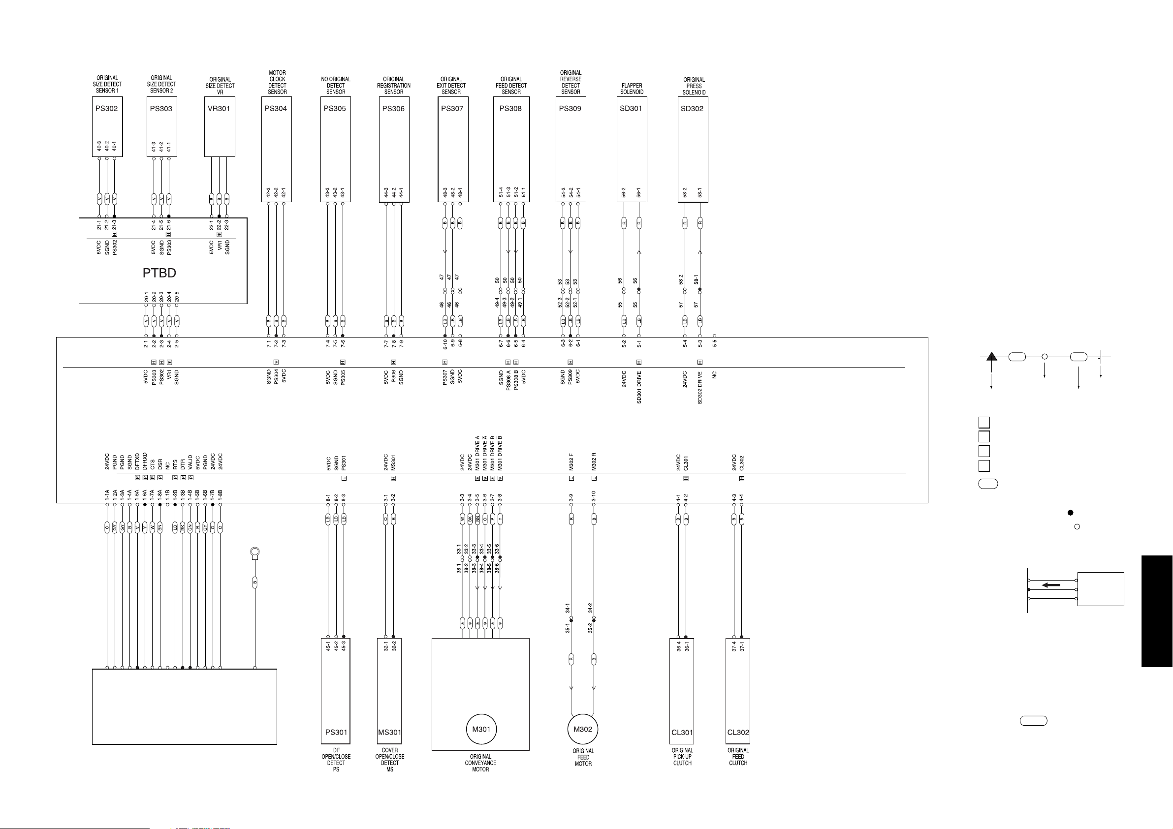
DF-315 OVERALL WIRING DIAGRAM
[How to see the diagram]
1.The signals shown reflect levels present
under normal idling conditions with
the main switch turned ON.
2.Wiring symbols in the figure are as follows.
(1) [Symbol]
(2)
Signal typs are as follows :
Active high
Active low
Analog signal
Pulse signal
(3) RC is ribbon cable.
(4) Signal flow
The solid black circle ( ) among
the connector symbols ( )
indicates the direction of signal flow.
Example)
(5) [Colour code]
BN - Brown B - Blue
R - Red V - Violet
O - Orange GY - Gray
Y - Yellow W - White
GN - Green BK - Black
LB - Light blue P - Pink
Example: Y/GN represents
green yellow striped pattern.
V
V
50-1
Crimp
Connector
Wire(Violet)
Faston
CB
5VDC
PS1
SGND
PS1
Direction of
signal flow
H
L
*
P
CN30-1
CN30-4
CN30-5
CN30-8
CN31-4
CN31-1
CN31-6
CN31-2
CN31-3
CN31-5
CN31-7
CN30-7
CN30-6
CN30-3
DFCB
5 DIAGRAM
CN30-2
MAIN BODY
5-35
 Loading...