

Page 1

3
DISASSEMBLY/ASSEMBLY
1 MAIN BODY
2 UNIT EXPLANATION
3 DIS./ASSEMBLY
Page 2

1 MAIN BODY
2
2 UNIT EXPLANATION
3 DIS./ASSEMBLY
This section explains how to disassemble and reassemble the machine.
When disassembling and reassembling the machine, follow the precautions given below.
1. Be sure the power cord has been unplugged from the wall outlet.
2. The disassembled parts must be reassembled following the disassembly procedure in reverse unless otherwise specified.
3. Care should be taken not to lose small parts. Care should also be
taken not to install machine parts in wrong places.
4. Do not operate the machine before installing all the disassembled
parts completely.
5. Removal of some screws is prohibited in this section. Never loosen
them.
Page 3
EXTERNAL SECTION
[1] Replacing the Ozone Filter
Caution: Be sure that the power cord has
been unplugged from the power
outlet.
a. Procedure
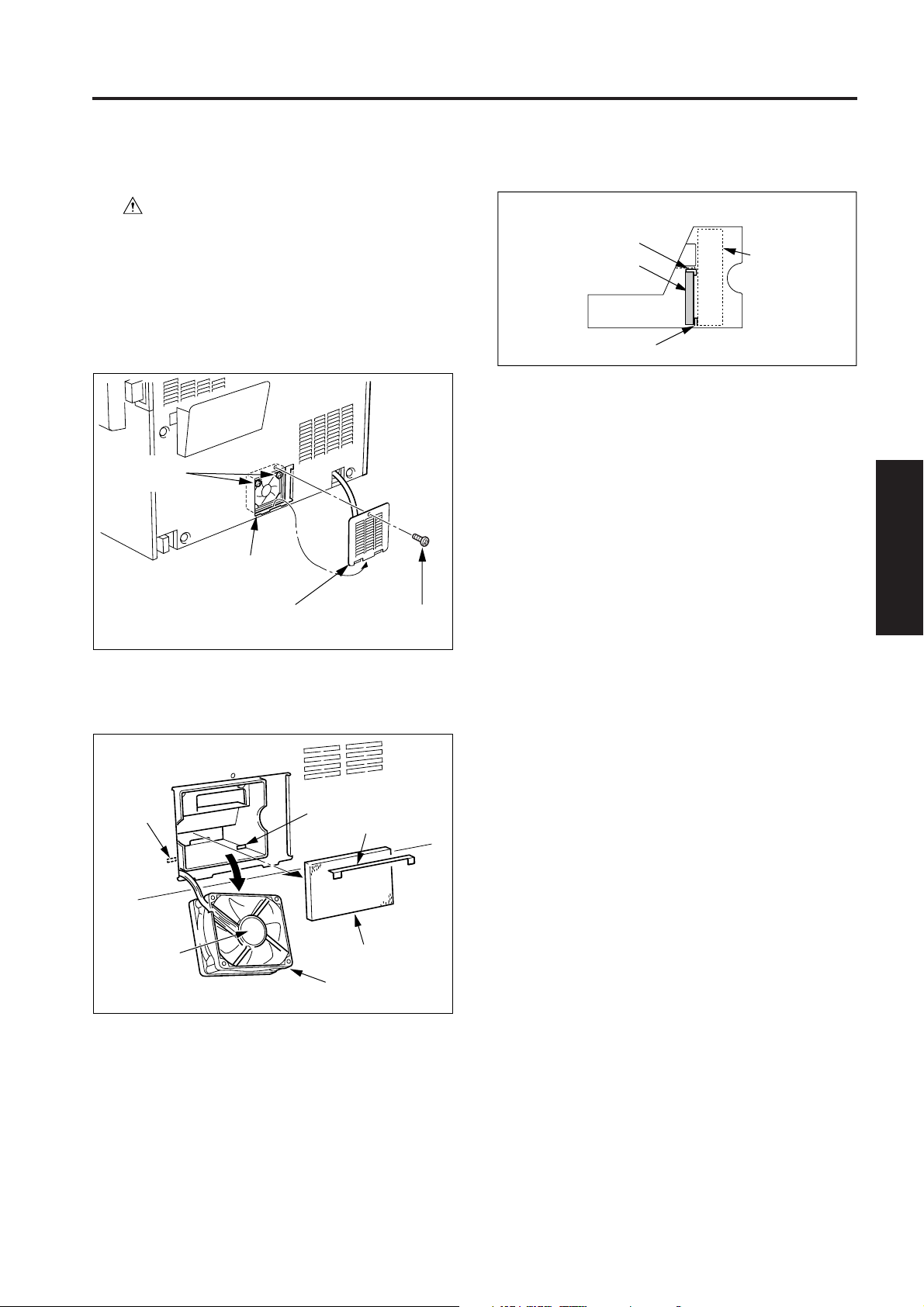
(1) Remove the one set screw, then remove the rear cover
(2).
(2) Remove the two set screws holding the conveyance
suction (FM4).
EXTERNAL SECTION
(5)
Reinstall the ozone filter in the opposite sequence to removal.
Filter retainer
Ozone filter
Hook
Caution 1: When installing the ozone filter, ensure
that the hook is at the front, as shown
in the figure.
FM4
1 MAIN BODY
2 UNIT EXPLANATION
Set screws
Conveyance
suction
Rear cover (2)
(3) Pull out the conveyance suction towards you. Do not
strain the wires during this process.
(4) Replacing the ozone filter.
Hook
Hook
Set screw
Filter retainer
Caution 2: Be sure to install the filter retainer.
3 DIS./ASSEMBLY
When reinstall
the toner filter,
place the label
on the outside.
Ozone filter
Conveyance suction
3-A-1
Page 4
EXTERNAL SECTION
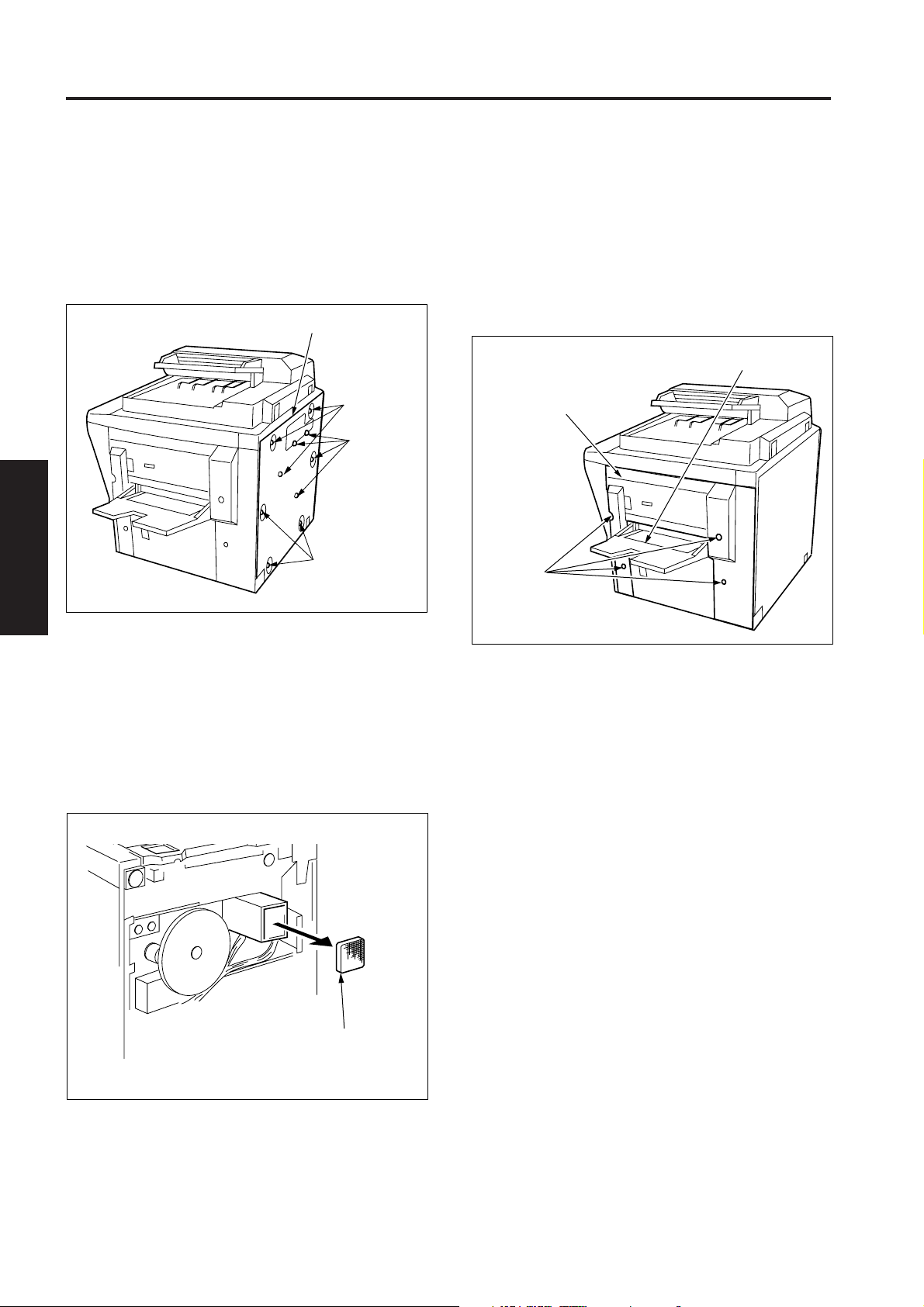
[2] Removing and Reinstalling the Rear
1 MAIN BODY
a. Procedure
2
(1) Remove the ten set screws, then remove the rear
2 UNIT EXPLANATION
3 DIS./ASSEMBLY
Cover
cover.
Rear cover
Set screws
Set screws
Set screws
[4] Removing and Reinstalling the Side
Cover (right)
a. Procedure
(1) Pull out the ADU and tray1, and open the front door.
(2) Open the by-pass tray.
(3) Loosen the four set screws, then remove the side cover
(right).
By-pass tray
Side cover (right)
Set screws
(2) Reinstall the rear cover in the opposite sequence to
removal.
[3] Replacing the Fixing Filter
a. Procedure
(1) Remove the rear cover.
(2) Replacing the fixing filter.
Fixing filter
(4) Reinstall the side cover (right) in the opposite sequence
to removal.
(3) Reinstall the fixing filter in the opposite sequence to
removal.
3-A-2
Page 5

DRIVE SECTION
DRIVE SECTION
[1] Disassembly and Reassembly
Caution : Disassembly and reassembly of the drive
section is not made in the normal service.
1 MAIN BODY
2 UNIT EXPLANATION
3 DIS./ASSEMBLY
3-B-1
Page 6

1 MAIN BODY
2
2 UNIT EXPLANATION
3 DIS./ASSEMBLY
Blank page
Page 7
READ SECTION
READ SECTION
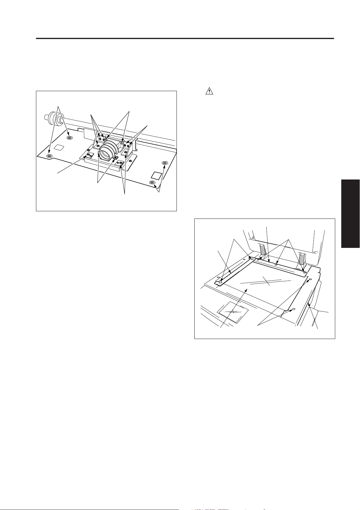
[1] Screws That Must Not Be Removed
a. The 16 set screws of the CCD unit
Screw that must
not be removed
Screws that must
not be removed
Screws that must
not be removed
Screws that must
not be removed
Screws that must not be
removed (on the (CCD)
CCD sensor board side)
Screws that must
not be removed
Screws that must
not be removed
Screws that
must not be
removed
[2] Removing and Reinstalling the CCD
Unit
Caution: Be sure that the power cord has
been unplugged from the power
outlet.
Caution: Be sure to perform image quality adjustment
after installing the CCD unit. (For details,
refer to “Adjustment section” in Field
Service.)
a. Procedure
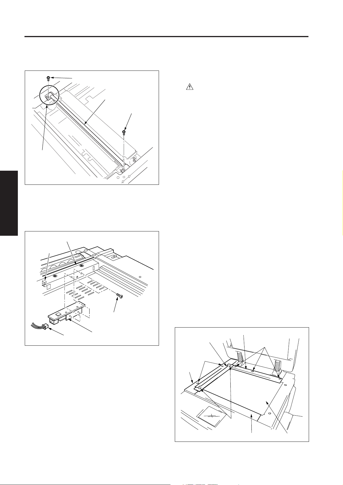
(1) Remove the two set screws (with step), then remove
the original stopper plate.
(2) Remove the two set screws, then remove the read
cover (right).
(3) Remove the three set screws (with step), then remove
the original stopper plate (rear).
(4) Remove the original glass.
Original stopper plate (rear)
Set screws
(with step)
Original stopper
plate
Set screws
(with step)
1 MAIN BODY
2 UNIT EXPLANATION
3 DIS./ASSEMBLY
3-C-1
Original glass
Set screws
Read cover (right)
Page 8

READ SECTION
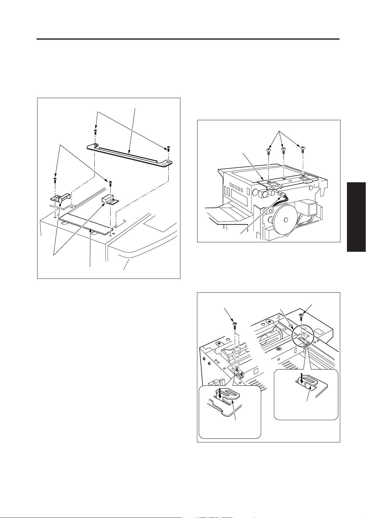
(5) Loosen the three set screws and remove the nine set
1 MAIN BODY
2
2 UNIT EXPLANATION
(6) Remove the side cover (right).
(7) Loosen the three lower set screws and remove the
3 DIS./ASSEMBLY
screws, then remove the lens light shield cover.
Set screws
Loosen the
set screws
Lens light
shield cover
Set screws
(Refer to “External section”)
three upper set screws, then remove the cover plate.
Loosen the three set screws
(8) Disconnect the two connectors (CN12,13) from the
image control board.
Image control board
Connector
(CN13)
Connector
(CN12)
(9) Remove the two set screws and loosen ground plate
fixed screw, then remove the CCD unit.
CCD unit
Set screws
Ground plate fixed screw
Set screws
Cover plate
(10) Reinstall the CCD unit in the opposite sequence to
removal.
3-C-2
Page 9
READ SECTION
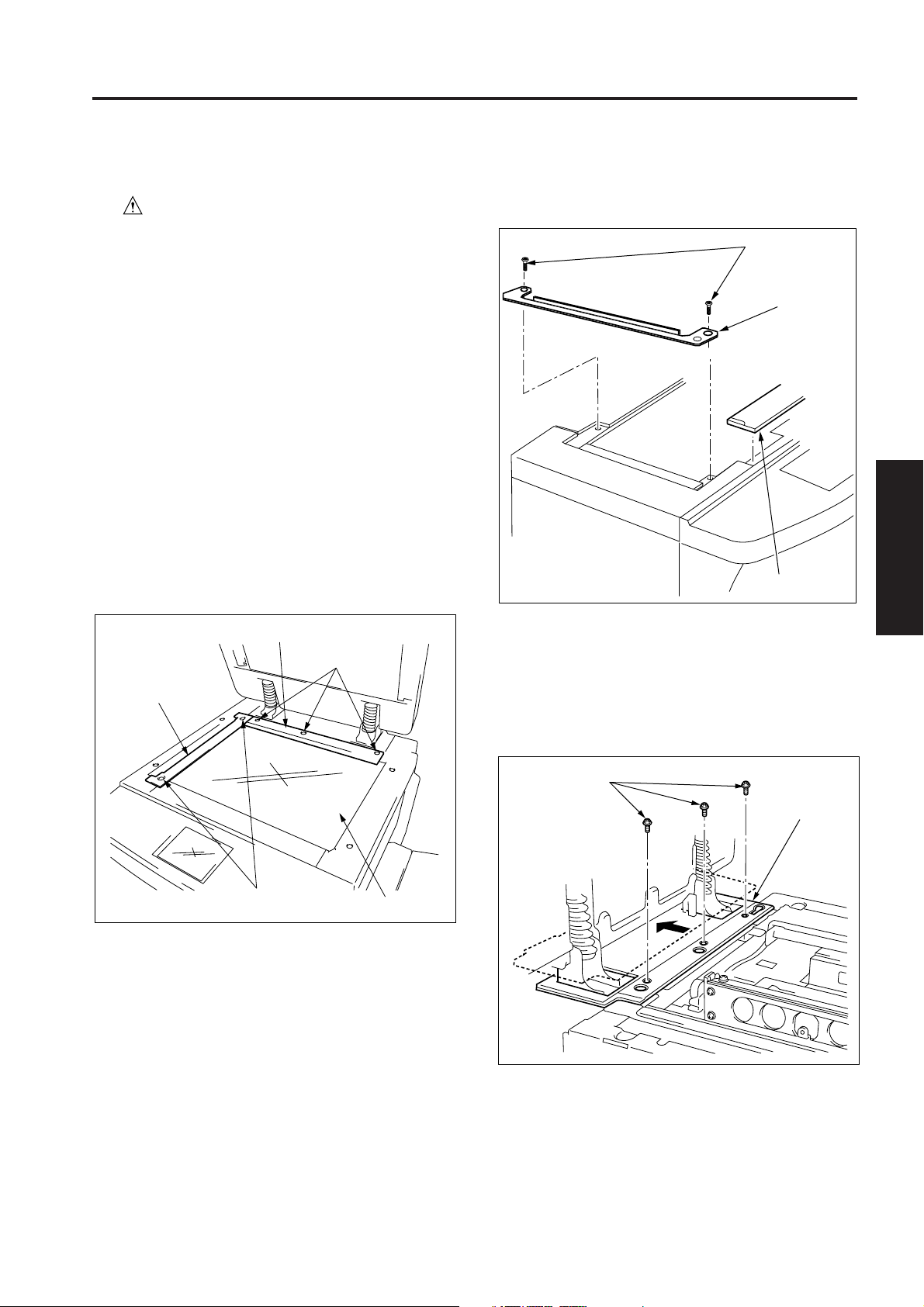
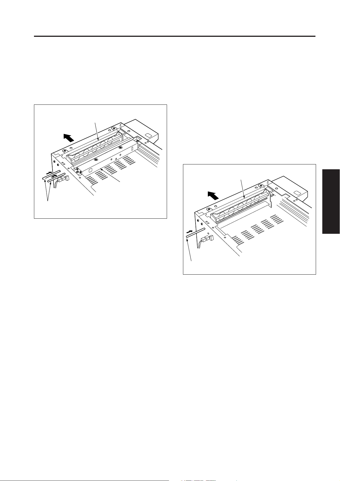
[3] Replacing the Exposure Lamp (L1)
Caution: Be sure that the power cord has
been unplugged from the power
outlet.
Caution 1: When removing the lamp terminals, be
sure to hold the contact terminal.
Caution 2: Never pull the cord.
Caution 3: Do not touch the glass of the L1 with
bare hands.
Caution 4: Check to ensure that you have not
forgotten to insert a connector or install
a screw, and also that a cord is not
crushed.
a. Procedure
(1) Remove the two set screws (with step), then remove
the original stopper plate.
(2) Remove the three set screws (with step), then remove
the original stopper plate (rear).
(3) Remove the original glass.
Original stopper plate (rear)
Set screws
(with step)
Original stopper
plate
(4) Remove the read cover (front).
(5) Remove the two set screws, then remove the glass
stopper plate.
Set screws
Glass
stopper
plate
Read cover (front)
Caution: When re-installing the original stopper
plate ensure that the film attached to the
original glass (1) is on top of the glass
stopper plate.
(6) Remove the three set screws, and move the read cover
(rear) to the rear.
1 MAIN BODY
2 UNIT EXPLANATION
3 DIS./ASSEMBLY
Set screws
(with step)
Set screws
Read cover (rear)
Original glass
(7) Move the exposure unit to the position of the notch in the
main body frame at the rear.
3-C-3
Page 10
READ SECTION
(8) Remove the two set screws from the exposure lamp (L1).
1 MAIN BODY
2
2 UNIT EXPLANATION
(9) Remove the two set screws, then remove the L1 in-
(10) Disconnect the connector (CN29) from the L1 inverter.
(11) Remove the set screw holding the exposure lamp on
3 DIS./ASSEMBLY
Set screw
Exposure lamp
Set screw
notch
verter (L1 INVB).
the rear side, then remove the exposure lamp.
Exposure lamp
Cord clamp
[4] Removing and Reinstalling the
Exposure Unit
Caution: Be sure that the power cord has
been unplugged from the power
outlet.
Caution 1: Never pull the cord.
Caution 2: Check to ensure that you have not
forgotten to insert a connector or install
a screw, and also that a cord is not
crushed.
Caution 3: Use a optics position adjusting jig
when installing the exposure unit.
Caution 4: Be sure to perform image quality
adjustment after installing the
exposure unit. (For details, refer to
“Adjustment section” in Field Service.)
Caution 5: When reinstalling the original stopper
plate ensure that the film attached to
the original glass (1) is on top of the
glass stopper plate.
Caution 6: Before installing the original glass (1),
be sure to clean it. (To prevent the
image defect)
Set screws
L1 inverter
Connector (CN29)
(12) Reinstall the exposure lamp in the opposite sequence
to removal.
Caution: Be sure to check the image after installing
the exposure lamp. (For details, refer to
“Adjustment section” in Field Service.)
a. Removal procedure
(1) Remove the two set screws (with step), then remove
the original stopper plate.
(2) Remove the three set screws (with step), then remove
the original stopper plate (rear).
(3) Remove the original glass.
(4) Remove the two set screws, then remove the read
cover (left).
(5) Remove the read cover (front).
Original stopper plate (rear)
Original stopper plate
Set screws
Read cover
(left)
Set screws
(with step)
Read cover (front)
Set screws
(with step)
Original glass
3-C-4
Page 11
READ SECTION
(6) Remove the two set screws, then remove the two glass
holders and original glass (1).
(7) Remove the two set screws, then remove the glass
stopper plate.
Set screws
Set screws
Glass stopper plate
(8) Remove the ten set screws, then remove the rear
cover.
(Refer to “External section”)
(9) Remove the RADF.
(Refer to the service handbook of the DF-315)
(10) Remove the three set screws, disconnect the relay
connector (CN91), then remove the read cover (rear).
Set screws
Read cover (rear)
Relay connector (CN91)
1 MAIN BODY
2 UNIT EXPLANATION
3 DIS./ASSEMBLY
Glass holders
Original glass (1)
(11) Move the exposure unit to the position of the notch in the
main body frame at the rear.
(12) Remove the four set screws each, then remove the two
exposure unit mounting pieces (front and rear) from the
exposure unit.
Set screws
Exposure unit mounting
piece (front)
notch
Exposure unit mounting
piece (rear)
Set screws
3-C-5
Page 12

READ SECTION
(13) Remove the exposure unit from the main body frame
1 MAIN BODY
(14) Disconnect the connector (CN28) from the L1 inverter
2
(15) Remove the one set screw, then remove the lamp cord
2 UNIT EXPLANATION
3 DIS./ASSEMBLY
while rotating it to the left.
(L1 INVB).
from the exposure unit.
Connector (CN28)
Set screw
Lamp cord
Exposure unit
b. Reinstallation procedure
(1) Open the front door and open the toner supply unit.
(2) Remove the one set screw holding the front door belt on
the left side.
(3) Remove the six set screws and disconnect the three
connectors (CN59, CN210, CN211), then remove the
operation panel.
Set screw
Connector (CN210)
Connector
(CN211)
Connector
(CN59)
Front door belt
Operation
panel
Set screws
Set screw
(4) Install the exposure unit to the main body.
(5) Install the front and rear mounting pieces of the expo-
sure unit in the slit of the exposure unit, then temporarily
fix them with four set screws each.
Set screws Set screws
Exposure unit mounting
Exposure unit mounting
piece (front)
piece (rear)
3-C-6
Page 13
READ SECTION
(6) Move the V-mirror unit to the paper exit side, then insert
the two optics position adjusting jigs into the exposure
unit mounting position from the front.
At this time, pass through the optics position adjusting
jigs into each unit and fasten the exposure unit and Vmirror unit.
V-mirror unit
Paper exit side
Exposure unit
Optics position adjusting jigs
(7) Fasten the exposure unit mounting pieces (front and
rear) with the four set screws.
(8) Remove the optics position adjusting jigs and install the
operation panel.
(9) The reminder of the installation procedure is in the
opposite sequence to removal.
[5] Removing the Optics Wire
Caution: Be sure to perform image quality adjustment
after replacing or re-installing the wire.
(For details, refer to “Adjustment section”
in Field Service.)
a. Procedure
(1) Remove the exposure unit.
(2) Remove the operation panel.
(3) Move the V-mirror unit to the paper exit side, then insert
the optics position adjusting jig into the V-mirror unit
mounting position from the front.
At this time, pass through the optics position adjusting
jig into the V-mirror unit and fasten the V-mirror unit.
V-mirror unit
Paper exit side
Optics position adjusting jig
1 MAIN BODY
2 UNIT EXPLANATION
3 DIS./ASSEMBLY
3-C-7
Page 14
READ SECTION
(4) Remove the rear cover, then free the wiring from the two
1 MAIN BODY
(5) Remove the five connectors (CN20 to CN24) and the
2
(6) Pull out the scanner drive board and disconnect the
2 UNIT EXPLANATION
3 DIS./ASSEMBLY
cord clamps on the rear side of the scanner drive board
(SCDB).
three set screws from the scanner drive board.
connector (CN11) on the image control board, then
remove the scanner drive board.
Caution: Be careful not to drop screws etc. between
the boards at the rear of the main body.
Connector (CN11)
Scanner drive board
Connector
(CN22)
Connector
Connector
(CN23)
Set screws
Connector
(CN20)
(CN24)
Connector
(CN21)
Set screw
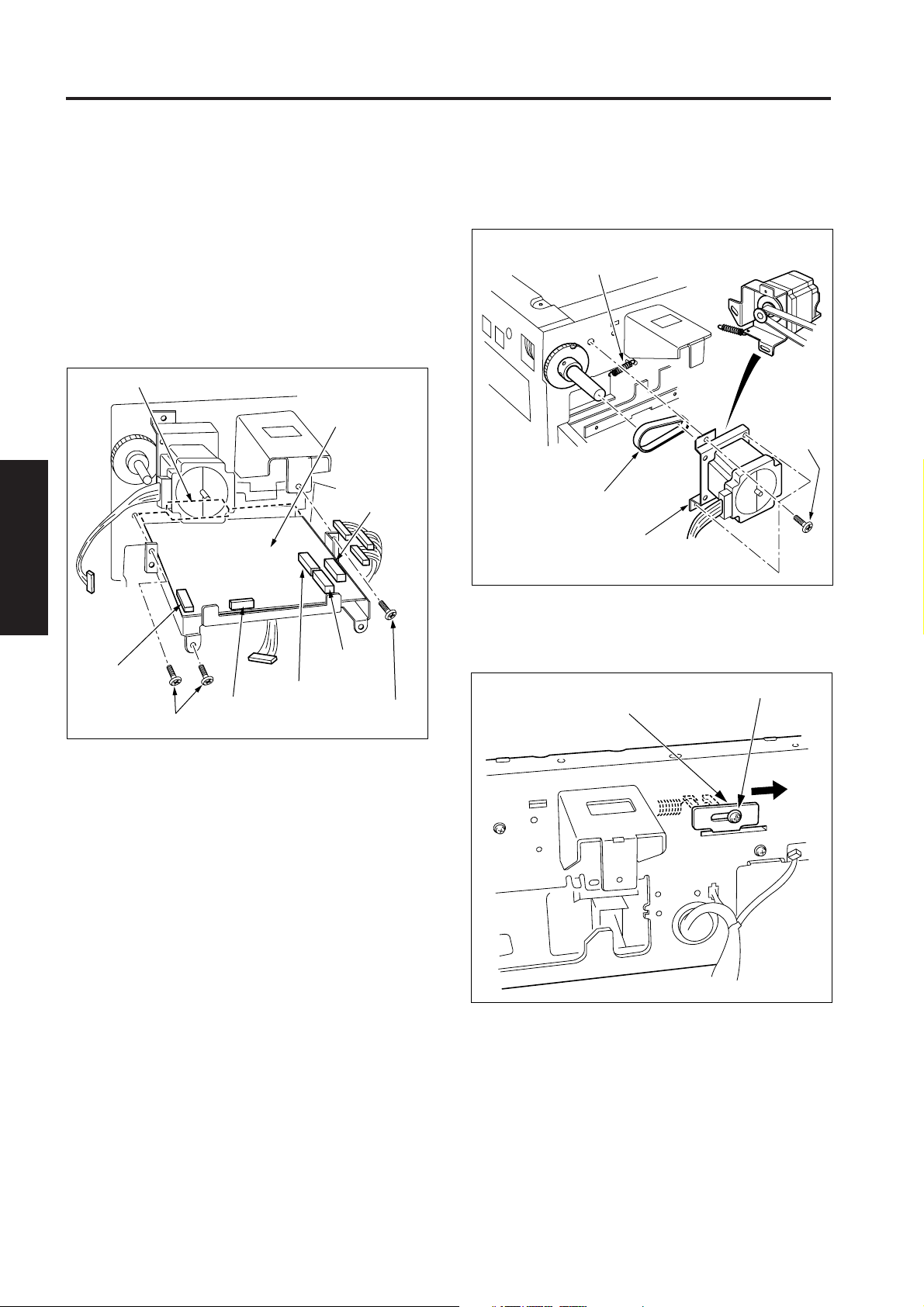
(7) Remove the three set screws and the belt tension
spring, then remove the scanner motor (M2) and timing
belt.
Belt tension spring
Set screws
Timing belt
Scanner moter
(8) Loosen the set screw holding the spring retainer (rear),
slide it to the paper exit side while pressing it with a flat-
blade screwdriver etc. to fix it again with the set screw.
Set screw
Spring retainer (rear)
3-C-8
Page 15
READ SECTION
(9) Slide the spring retainer (front) to the paper exit side to
fix it in the same way.
Set screw
Spring retainer (front)
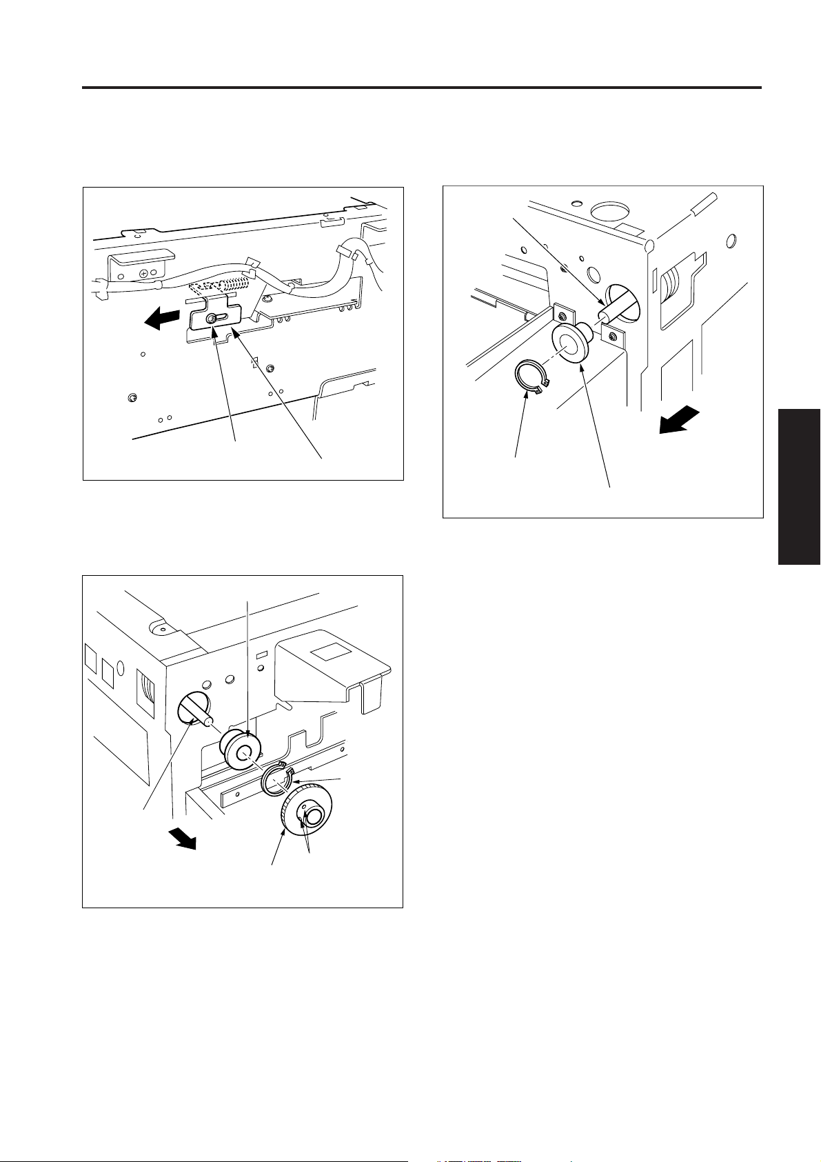
(10) Remove the two set screws, then remove the read
driven pulley.
(11) Remove the C-ring and bearing on the rear side of the
machine. Be careful not to scratch the pulley shaft.
Bearing
(12) Remove the one C-ring and bearing on the front side of
the machine from the pulley shaft in the same way.
Pulley shaft
Front side of
C-ring
Bearing
the machine
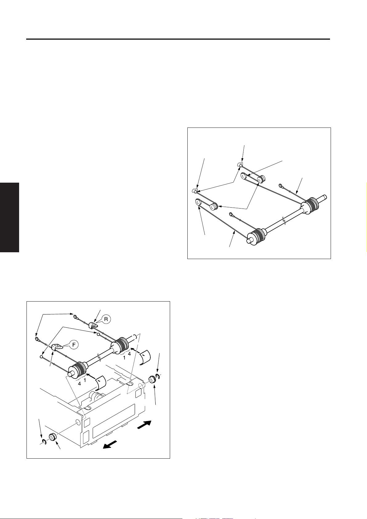
(13) Remove the two optics wires (front and rear).
(14) Remove the pulley shaft from the main body. At this
time, if the leading edge of the set screw holding the
optics rail contacts with the shaft, loosen the set screw.
1 MAIN BODY
2 UNIT EXPLANATION
3 DIS./ASSEMBLY
Pulley shaft
Rear side of
the machine
C-ring
Set screws
Read driven
pulley
3-C-9
Page 16
READ SECTION
[6] Installing the Optics Wire
1 MAIN BODY
2
2 UNIT EXPLANATION
(1) Insert the metal bead at the mid-point of the optics wire
3 DIS./ASSEMBLY
(2) Provisionary fasten the wire to the drive pulley with a
Caution 1: When winding the wire around the
pulley, be sure to run the wire tightly to
ensure that it does not ride up the side
of the pulley.
Caution 2: When reinstalling or replacing the
optics wire, be sure to use the optics
position adjusting jig.
Caution 3: Be sure to perform image quality
adjustment after replacing or reinstalling
the wire. (For details, refer to “Adjustment
section” on Field Service.)
(front) into the mounting hole of the drive pulley, then
wind four turns around the pulley to the outside, and one
turn to the inside, starting this position.
(a) Use the optics wire marked “F” on the exposure unit
mounting piece to the front side and “R” to the rear
side.
(b) Wind the optics wire so that the side with the metal
bead at the leading edge is outside (front/rear) of the
pulley shaft.
(c) Wind the optics wire so that the side with the metal
bead at the leading edge passes under the drive
pulley.
gummed tape so that the wire winding is not lost, after
that, fix the pulley shaft to the frame with the bearings
and E-rings.
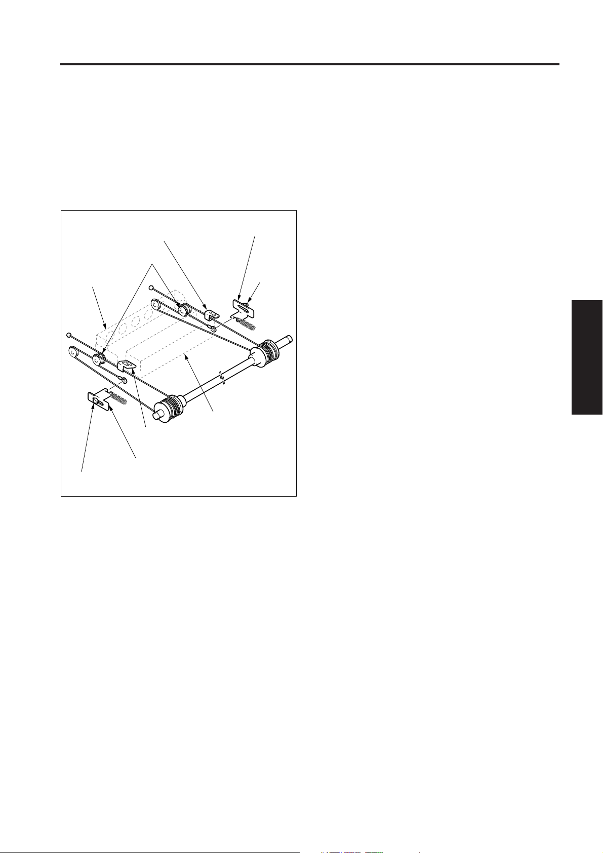
(3) Pass the optics wire (front) of the metal bead side
around the pulley 1 (V-mirror unit) then pass it around
the inside slit of the pulley 2 (exposure unit). Pass
around the optics wire (rear) at the same procedure.
(4) Remove the optics position adjusting jig.
(5) Fasten each metal bead at the leading edge of the
optics wire (front and rear) to the slits of the main body
frame on the paper exit side.
Slit
Slit
(front side of
the machine)
Pulley 1
Optics wire (front)
(rear side of the machine)
Pulley 1
Optics wire (rear)
Metal bead
Pulleys 2
Round
terminals
Metal
beads
Exposure unit
mounting piece
(front)
E-ring
Bearing
Exposure unit mounting piece (rear)
Gummed tape
(for provision)
E-ring
Bearing
Rear side of
the machine
Front side of
the machine
3-C-10
Page 17
READ SECTION
(6) Pass the side with the round terminal of the optics wire
(front) to the outside of the pulley 2 and hook the round
terminal on the spring retainer. Hook the optics wire
(rear) in the same way.
(7) Install the exposure unit to the main body.
(8) Loosen each set screw fasting the spring retainers.
(9) Fasten each set screw of the spring retainers after
moving the exposure unit two or three times.
Exposure unit mounting
piece (rear)
Pulleys 2
V-mirror unit
Spring ratainer
(rear)
Set screw
1 MAIN BODY
2 UNIT EXPLANATION
3 DIS./ASSEMBLY
Exposure unit
Exposure unit mounting
piece (front)
Spring ratainer (front)
Set screw
(10) The reminder of the installation procedureis in the
opposite sequence to removal.
3-C-11
Page 18

1 MAIN BODY
2
2 UNIT EXPLANATION
3 DIS./ASSEMBLY
Blank page
Page 19
WRITE UNIT
WRITE UNIT
[1] Removing and Reinstalling the Write
Unit
Warning1:
Warning2:
Warning3:
Caution: Be sure that the power cord has
Caution 1: When removing the write unit, do not
Caution 2: When installing the write cover, check
Do not energize the write unit when
it is not installed in the machine.
Never remove the cover from the write
unit with the circuit being energized.
(If the laser beam gets into your eyes,
you may lose your sight.)
Never remove the write unit for at
least two minutes after turning OFF
the main switch.
been unplugged from the power
outlet.
make contact with the write mirror and
dust-proof glass. (prevention of the
scratch and stain for the mirror.)
that the write cover is got caught in
the ground spring.
a. Procedure
(1) Remove the original glass.
(Refer to “Read section”)
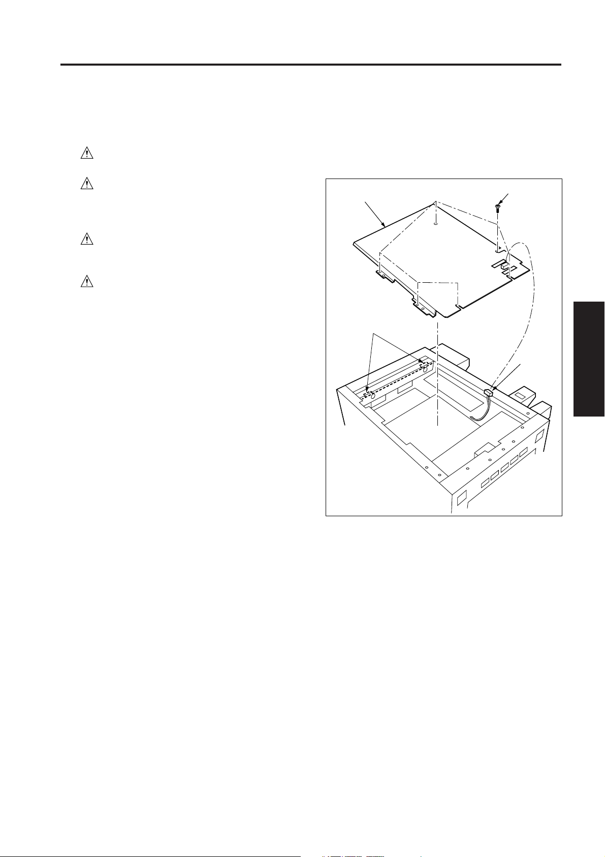
(2) Remove the six set screws and disconnect the connec-
tor (CN93), then remove the write cover.
Write cover
Ground springs
Set screws
Connector
(CN93)
1 MAIN BODY
2 UNIT EXPLANATION
3 DIS./ASSEMBLY
3-D-1
Page 20

WRITE UNIT
(3) Remove the rear cover.
1 MAIN BODY
(4) Remove the three set screws holding the scanner drive
2
2 UNIT EXPLANATION
3 DIS./ASSEMBLY
(5) Remove the side cover (right).
(6) Remove the cover plate.
(7) Disconnect two connectors (CN12,13) from the image
(8) Pull out the scanner drive board into the rear side of the
(9) Remove the two set screws and pull out the image
(Refer to “External section”)
board (SCDB).
Caution: Be careful not to drop screws etc. between
the boards at the rear of the main body.
Scanner drive board
Set screws
Set screw
(Refer to “External section”)
(Refer to “Read section”)
control board (ICB).
(Refer to “Read section”)
machine and disconnect the connector (CN11) on the
image control board from the scanner drive board.
control board.
(10) Remove the five set screws, then remove the printer
side cover.
Printer side cover
Set screws
Set screws
(11) Disconnect the seven connectors (CN1, CN2, CN5,
CN6, CN7, CN200, CN505) and free the wiring from the
six cord clamps.
(12) Remove the nine set screws, then remove the board
stay assembly .
Connector
(CN200)
Connector
(CN1)
Connector
(CN2)
Set screws
Connector (CN7)
Cord
clamp
Connector
(CN505)
Connector
(CN5)
Set screws
Image control board
Set screw
Connector
(CN13)
Connector
(CN12)
Connector
(CN11)
Scanner drive board
Set screw
3-D-2
Cord clamps
Connector
(CN6)
Board stay
assembly
Set screws
Page 21

WRITE UNIT
(13) Disconnect the connector (CN44).
(14) Remove the four set screws, then remove the write unit
Write unit
Connector (CN44)
Set screws
[2] Cleaning the Dust-proof Glass
1 MAIN BODY
a. Procedure
(1) Remove the drum unit.
(Refer to “Drum unit”)
(2) Reach inside the main body and using a soft cloth wipe
the dirt from the dust-proof glass.
Dust-proof glass
2 UNIT EXPLANATION
.
Drum shaft
3 DIS./ASSEMBLY
Dust-proof glass
Set screws
(15) Reinstall the write unit in the opposite sequence to removal.
Write
unit
Dust-proof glass
Mirror
Mirror
Insert hand from here
Drum shaft
3-D-3
Page 22

1 MAIN BODY
2
2 UNIT EXPLANATION
3 DIS./ASSEMBLY
Blank page
3-C-4
Page 23

DRUM UNIT
DRUM UNIT
[1] Removing and Reinstalling the Drum
Unit
Caution: Be sure that the power cord has
been unplugged from the power
outlet.
Caution 1: Do not shake the drum unit up and
down, side to side, or repeatedly move
back and forth when removing or
installing and handle it slowly keeping
it horizontal to its axis.
Caution 2: When removing or installing the drum
unit, pull out the drum coupling shaft
that is on your side and work with the
lock mechanism fixed in place.
Caution 3: When installing the drum unit, clean
the drawer connector on the back side
of the drum unit with the blower brush.
Caution 4: After installing the drum unit back into
the main unit, rotate the charge
cleaning knob back and forth about 2
times.
Caution 5: When removing the drum unit, be sure
to place the drum cover over it and
store the drum carriage in a dark place.
(2) Release the conveyance lever.
(3) Remove the Transfer/separation corona unit from the
main body.
(Refer to “Corona unit”)
(4) Remove the one set screw holding the drum unit.
Set screw
Drum coupling shaft
Transfer/separation
corona unit
Conveyance lever
: Screws that must not be removed
1 MAIN BODY
2 UNIT EXPLANATION
3 DIS./ASSEMBLY
Caution 6: Be careful not to rotate the drum when
installing or removing the drum unit. If
you rotate the drum in the direction
opposite to the direction in which it
rotates during a copy operation, you
risk damaging the cleaning blade.
a. Removal procedure
(1) Open the front door, loosen the one set screw, release
the lock plate of the toner supply unit, then open the
toner supply unit to the paper feed side.
Lock plate
Toner supply unit
Set screw
(5) Slowly pull the drum unit out careflly to the front.
b. Reinstallation procedure
(1) Make sure that the drum coupling shaft and the drum
flange are correctly meshed.
(2) Slowly insert the drum unit into the main body until the
drum coupling shaft hit the drum shaft and it is pushed
out slightly toward you. (When the drum coupling shaft
and the drum flange are not correctly meshed, the drum
coupling shaft hit the drum shaft and it is pushed out
toward you.)
Caution: At this time, do not squeeze the drum unit
into the main body by force. Also, do not
rotate the drum coupling shaft with the
drum unit is squeezed into the main body.
(3) With the drum coupling shaft is pushed out slightly
toward you, rotate the drum coupling shaft in the
forwarding direction, and mesh the drum coupling shaft
and the drum shaft correctly.
(4) Securely reinstall the drum unit to the main body and fix
it with the set screw.
(5) Reinstall the drum unit in the opposite sequence to
removal.
3-E-1
Page 24

DRUM UNIT
[2] Removing and Reinstalling the Drum
1 MAIN BODY
2
2 UNIT EXPLANATION
3 DIS./ASSEMBLY
Caution 1: Be careful not to touch the drum or the
cleaning blade with bare hands, or
damage these parts.
Caution 2: When removing and re-installing the
drum, be careful not to hit the drum on
the metal plate section of the cleaning
blade.
Caution 3: When leaving the drum to stand, be
sure to place the drum cover over it
and store it in a dark place.
Caution 4: When installing the drum and cleaning
blade, regardless of the new or old
parts, apply setting powder to all of the
drum surface and the both ends of the
cleaning blade.
Caution 5: After applying setting powder to the
drum, carry out the following work
before installing the drum unit into the
main body.
• To obtain the correct toner density,
clean setting powder leakage on the
surface of the sensor on the toner
control sensor board with an alcohol
damped cloth.
Caution 6: When installing the drum, be careful of
the orientation of the drum. The gear
side of the drum is rear the side.
Caution 7: When installing a new drum, be sure to
enter code 91-1 of the 47 mode and
reset the drum counter. Then, be sure
to preform the charging grid voltage
adjustment and PWM gamma (patch)
adjustment. (For details, refer to
“Adjustment section” in Field Service.)
a. Removal procedure
(1) Pull out the drum coupling shaft, then fasten it with the
lock lever.
(2) Remove the drum unit from the main body.
(3) Remove the charging corona unit and developing unit
from the drum unit. (For the sequence of removing
these parts, refer to “Corona unit” and “Developing
unit”.)
(4) Holding the both ends of the drum and lower the
cleaning unit, then shake the drum unit few times.
(5) Check that the toner is not left between cleaning blade
and toner collection sheet.
Fasten
Release
Drum coupling shaft
(6) Gently lift out the drum while holding it at both ends to
ensure that you do not damage the photosensitive
surface.
Lock lever
3-E-2
Drum
Page 25

DRUM UNIT
b. Reinstallation procedure
Caution: Push down both ends of the toner
collection sheet towards you and confirm
that the entire drum is in contact without
any space.
(1) Remove the cleaning blade.
(Refer to “Cleaning / toner recycle section”.)
(2) Apply setting powder into the entire surface of the drum.
(3) Install the drum to the drum casing and release the lock
lever, then lock the drum coupling to the drum flange.
(4) Remove the drum support tool from the main body and
insert it into the drum (gear side).
Drum support
tool
Set screw
Fixing unit
Drum support
tool
(5) Rotate the drum counterclockwise once.
(6) Rotate the drum clockwise a bit.
(7) Check that setting powder collected by the toner collec-
tion sheet remains on the surface of the drum to the both
ends of the drum without a clearance.
Reverse direction
Toner collection sheet
Drum
Forward direction
Setting powder
(8) Remove the drum support tool from the drum.
(9) Pull out the drum coupling shaft, then fasten it with the
lock lever.
(10) Remove the drum from the drum casing.
(11) Gently wipe setting powder on the surface of the drum
with a cleaning pad.
(12) Apply setting powder to the entire surface of the drum.
(13) Apply toner to both ends of the cleaning blade edge and
setting powder to the middle of the drum.
(14) Install the drum to the drum casing, release the lock
lever, lock the drum coupling to the drum flange and
install the drum support tool to the drum.
(15) Rotate the drum in the forward direction and check that
there is no setting powder falling and curling of the
cleaning blade.
(16) The reminder of the installation procedure is in the
opposite sequence to removal.
1 MAIN BODY
2 UNIT EXPLANATION
3 DIS./ASSEMBLY
3-E-3
Page 26

DRUM UNIT
[3] Removing and Reinstalling the
1 MAIN BODY
2
a. Procedure
(1) Remove the drum unit from the main body.
2 UNIT EXPLANATION
(2) Remove the drum from the drum unit.
(3) Disconnect the relay connector (CN62) and free the
(4) Remove the Separation swing spring and the two
3 DIS./ASSEMBLY
Separation Claws
Caution 1: Take care not to damage the drum
when removing the separation claws.
Caution 2: Be careful of the orientation and
position of the separation claws when
re-installing the claws.
Caution 3: Do not touch the cleaning blade or the
drum with the bare hands.
(Refer to “Drum unit section”)
wiring from the cord clamps.
positioning screws, then remove the separation claws
unit.
Separation claws unit
(5) Remove the separation press spring from each of the
separation claws.
(6) While pressing down the separation fulcrum shaft,
remove the separation claw (two).
Separation press spring
Separation
claw
Separation fulcrum shaft
Cord clamps
Relay connector
(CN62)
Caution: Take care not to lose the collar of the
positioning screw.
Positioning
screws
Separation
swing spring
(7) Reinstall the separation claws in the opposite sequence
to removal.
3-E-4
Page 27

CORONA UNIT SECTION
CORONA UNIT SECTION
[1] Removing and Reinstalling the
Charging Corona Unit and PCL
Caution: Be sure that the power cord has
been unplugged from the power
outlet.
Caution: If you installed the PCL, ensure that it is
securely tightened.
a. Procedure
(1) Remove the drum unit from the main body.
(Refer to “Drum unit section”)
(2) Disconnect the relay connector (CN62) from the drum
unit.
(3) Lift up the charging corona unit at the rear side first then
while moving it to the rear raise the front side.
(4) Remove the PCL from the hooks of the charging corona
unit.
Hook
Charging corona unit
Hook
[2] Removing and Reinstalling the
Transfer and Separation Corona Unit
Caution: Be sure that the power cord has
been unplugged from the power
outlet.
a. Procedure
(1) Open the front door, and release the conveyance lever.
(2) Remove the one set screw, then pull the transfer and
separation corona unit forward to remove it.
Caution: Take care not to drop the set screws into
the main body.
1 MAIN BODY
2 UNIT EXPLANATION
3 DIS./ASSEMBLY
PCL
Relay connector (CN62)
(5) Reinstall the charging corona unit and PCL in the
opposite sequence to removal.
Set screw
Conveyance lever
(3) Reinstall the transfer and separation corona unit in the
opposite sequence to removal.
Transfer and separation corona unit
3-F-1
Page 28

CORONA UNIT SECTION
[3] Removing and Reinstalling the
1 MAIN BODY
2
a. Procedure
(1) Remove the drum unit from the main body.
(2) Remove the charging corona unit.
(3) Remove the two charging control springs, then remove
2 UNIT EXPLANATION
(4) Remove dirt from the charging control plate by gently
3 DIS./ASSEMBLY
Charging Control Plate
Caution: Install the charging control plate so that
the end with the round holes has the
springs hooking it to the rear of the
charging corona unit.
(Refer to “Drum unit section”)
the charging control plate.
dabbing it with a cloth moistened with drum cleaner,
then remove any remaining dirt with a blower brush.
Charging control springs
Charging control plate
(5) Reinstall the charging control plate in the opposite
sequence to removal.
Caution: When installing the charging control
springs, be careful of the attachment
direction.
Charging
control spring
Charging
control spring
3-F-2
Page 29

CORONA UNIT SECTION
[4] Replacing the Charging Wire
a. Procedure
(1) Remove the drum unit from the main body.
(Refer to “Drum unit section”)
(2) Remove the charging corona unit.
(3) Remove the charging control plate.
(4) Remove the charging cover (front and rear) each.
(5) Remove the charging wire cleaning block (C).
(6) Remove the charging wire cleaning block (D).
(7) Remove the one spring, then remove the charging wire.
Charging cover (rear)
Charging wire cleaning block (C)
Charging cover
(front)
Charging wire
cleaning block (D)
[5] Replacing the Transfer and
Separation Wires
a. Procedure
(1) Remove the transfer and separation corona unit from
the main body.
(2) While lifting the transfer entrance plate, remove the two
springs.
(3) Remove the one set screw, then remove the transfer
entrance plate.
Transfer entrance plate
Set screw
Spring
Spring
1 MAIN BODY
2 UNIT EXPLANATION
3 DIS./ASSEMBLY
Spring
Charging wires
(8) Reinstall the charging wire in the opposite sequence to
removal.
(4) Remove the five hooks from the transfer and separation
corona unit with tweezers, then remove the plunging
prevention plate.
Plunging prevention
plate
Hooks
Hooks
3-F-3
Page 30

CORONA UNIT SECTION
(5) Remove the spark arrestor plates (front and rear).
1 MAIN BODY
2
2 UNIT EXPLANATION
3 DIS./ASSEMBLY
Spark arrestor
plate (rear)
Spark arrestor plate (front)
[6] Replacing the Charging Wire
Cleaning Blocks (C) and (D)
a. Procedure
(1) Remove the drum unit from the main body.
(Refer to “Drum unit section”)
(2) Remove the charging corona unit.
(3) Remove the charging control plate.
(4) Remove the charging wire cleaning block (C).
Changing control spring
Changing control plate
Charging wire
cleaning block (C)
(6) Remove the springs (one spring) for each wire, then
remove the transfer wire and separation wire.
(7) Remove the support rubber from each wire.
Separation wire
Support rubbers
Springs
(8) Reinstall the transfer and separation wires in the oppo-
site sequence to removal.
Support rubbers
Transfer wire
Caution: When installing the charging control
spring, be careful of the attachment
direction of the spring.
Charging
control spring
Charging
control spring
3-F-4
Page 31

CORONA UNIT SECTION
(5) Remove the charging cover (rear).
(6) Remove the charging wire from the spring.
(7) Remove the charging wire cleaning block (D) and
cleaner mount assembly.
Charging cover (rear)
Charging wire
cleaning block
(D)
Cleaner
mount assembly
Charging wire
Spring
1 MAIN BODY
2 UNIT EXPLANATION
3 DIS./ASSEMBLY
(8) Reinstall the charging wire cleaning block (C) and (D) in
the opposite sequence to removal.
3-F-5
Page 32

1 MAIN BODY
2
2 UNIT EXPLANATION
3 DIS./ASSEMBLY
Blank page
Page 33

DEVELOPING UNIT
DEVELOPING UNIT
[1] Screws That Must Not Be Removed
Caution: Never do any adjustments, remove set
screws, or any similar task at the market in
regards to the items below.
(1) The two set screws of the developing regulating plate.
(2) The one set screw of the magnet angle adjustment
plate.
Screw that must
not be removed
Screw that must
not be removed
Screw that must
not be removed
[2] Removing and Reinstalling the
Developing Unit
a. Procedure
(1) Remove the drum unit from the main body.
(Refer to “Drum unit section”)
(2) Tap the recycle pipe a few times around the discharge
opening to drop recycled toner into the developing unit.
Tap this part few times
(3) Disconnect the relay connector (CN65).
(4) Loosen the two set screws, then remove the developing
unit from the drum unit.
1 MAIN BODY
2 UNIT EXPLANATION
3 DIS./ASSEMBLY
Set screw
Relay connector (CN65)
Developing unit
Set screw
3-G-1
Page 34

DEVELOPING UNIT
(5) Place paper under the toner exit of the toner recycle
1 MAIN BODY
2
2 UNIT EXPLANATION
(6) Reinstall the developing unit in the opposite sequence
3 DIS./ASSEMBLY
pipe (for catching remaining toner).
Place paper
to removal.
[3] Replacing the Developer
Caution 1: When replacing the developer, take
care that dirt does not become mixed
with it.
Caution 2: After supplying new developer, never
rotate the developing drive input gear
(2) in the clockwise (reverse direction)
direction.
Caution 3: After supplying new developer, make
sure to perform 36 mode L detection
adjustment (For details, refer to
"Adjustment section" in Field Service).
Reverse
direction
Developing drive
input gear (2)
a. Procedure
(1) Remove the drum unit from the main body.
(Refer to “Drum unit section”)
(2) Remove the developing unit from the drum unit.
(3) Release the hooks on the developing unit cover, then lift
up and remove the cover.
Hooks
Developing unit cover
3-G-2
Page 35

DEVELOPING UNIT
(4) Tilt the developing unit so that the agitator screw side is
downward, then rotate the developing drive input gear
(2) in the counterclockwise direction until all of the
developer adhering to the inside of the developing unit
and the developing sleeve is discharged.
(5) Wipe the developer remaining on the developing regu-
lation plate.
Developing regulating plate
Agitator screws
Rotate
Developing drive
input gear(2)
(6) Supply fresh developer evenly from the top of the
agitator screw.
(7) Rotate the developing drive input gear (1) in the
counterclockwise direction until all of the developer
enters the inside of the developing unit.
1 MAIN BODY
2 UNIT EXPLANATION
3 DIS./ASSEMBLY
Developing drive
input gear (1)
Toner leakage
prevention sheets
(8) Repeat steps (6) and (7) until all of the developer has
been supplied to the developing unit.
(9) Rotate the developing drive input gear (2) in the
counterclockwise direction, and check that the developer bristles along the entire length of the developing
sleeve.
(10) Install the developing cover
(11) Check that the toner leakage prevention sheet is not
caught by the developing unit cover.
(12) Install the developing unit on the drum unit.
3-G-3
Page 36

1 MAIN BODY
2
2 UNIT EXPLANATION
3 DIS./ASSEMBLY
Blank page
Page 37

TONER SUPPLY UNIT
TONER SUPPLY UNIT
[1] Removing and Reinstalling the Toner
Cartridge
a. Procedure
(1) Open the front door, then swing out the toner supply
unit.
(2) Pull the pressure lever, then remove the toner cartridge.
Toner cartridge
1 MAIN BODY
2 UNIT EXPLANATION
3 DIS./ASSEMBLY
Pressure lever
(3) Reinstall the toner cartridge in the opposite sequence to
removal.
3-H-1
Page 38

1 MAIN BODY
2
2 UNIT EXPLANATION
3 DIS./ASSEMBLY
Blank page
Page 39

CLEANING/TONER RECYCLE UNIT
CLEANING/TONER RECYCLE UNIT
[1] Removing and Reinstalling the
Cleaning Blade
Caution: Be sure that the power cord has
been unplugged from the power
outlet.
Caution 1: Do not touch the edge of the cleaning
blade with bare hands.
Caution 2: Push down both ends of the toner
collection sheet towards you and
confirm that the entire drum is in
contact without any space.
Caution 3: When installing the drum and cleaning
blade, apply setting powder to the
entire surface of the drum and also the
cleaning blade, regardless of whether
the drum and cleaning blade are new
or old type parts.
Caution 4: Once the drum has been applied with
setting powder, carry out the following
work before installing the drum unit to
the main body.
• To obtain the correct toner density,
clean setting powder leakage on the
surface of the sensor on the toner
control sensor board with an alcohol
damped cloth.
a. Procedure
(1) Remove the drum unit from the main body.
(Refer to “Drum unit section”)
(2) Remove the charging corona unit.
(Refer to “Corona unit section”)
(3) Remove the developing unit and drum from the drum
casing.
(4) Remove the two set screws, then remove the cleaning
blade.
Cleaning blade
Set screw
Set screw
Drum casing
(5) Reinstall the cleaning blade in the opposite sequence to
removal.
1 MAIN BODY
2 UNIT EXPLANATION
3 DIS./ASSEMBLY
3-I-1
Page 40

1 MAIN BODY
2
2 UNIT EXPLANATION
3 DIS./ASSEMBLY
Blank page
Page 41

PAPER FEED UNIT
PAPER FEED UNIT
[1] Removing and Reinstalling the By-
pass Paper Feed Unit
Caution: Be sure that the power cord has
been unplugged from the power
outlet.
a. Procedure
(1) Remove the side cover (right).
(2) Remove the two relay connectors (CN80, CN81) of the
by-pass paper feed unit.
(3) Remove the one set screw, then remove the paper feed
door.
Relay connector (CN81)
Relay connector (CN80)
[2] Removing and Reinstalling the Paper
Feed Unit
Caution: Be sure that the power cord has
been unplugged from the power
outlet.
a. Procedure
(1) Pull out ADU and the paper feed tray in the forward
direction.
(2) Remove the one set screw, then pull out the paper feed
unit with the rail as guide of the paper feed tray toward
you.
ADU
Set screw
1 MAIN BODY
2 UNIT EXPLANATION
3 DIS./ASSEMBLY
Set screw
Paper feed
door
(4) Remove the four set screws, then remove the by-pass
paper feed unit.
Set screws
By-pass paper feed unit
Set screws
Paper feed
unit
Paper feed tray
(3) Reinstall the paper feed unit in the opposite sequence
to removal.
Caution: Be sure to make a copy after installing the
paper feed unit and check that paper is fed
normally.
If the rocking gear is not held by the 1st
paper feed solenoid, the paper feed is not
made normally.
(5) Reinstall the by-pass paper feed unit in the opposite
sequence to removal.
3-J-1
Page 42

PAPER FEED UNIT
[3] Replacing the By-pass Paper Feed
1 MAIN BODY
a. Procedure
2
(1) Remove the by-pass paper feed unit.
(2) Remove the one stop ring and bearing.
2 UNIT EXPLANATION
3 DIS./ASSEMBLY
Rubber
Bearing
Stop ring
(3) Press the plunger of the by-pass SD (SD4) until claw of
the by-pass solenoid releases from the gear of the
torque limiter.
(4) Pull out the by-pass drive shaft while pressing the
plunger of the by-pass SD, then remove the by-pass
paper feed roller.
(5) Remove the by-pass paper feed rubber from the by-
pass paper feed roller.
By-pass paper feed rubber
By-pass paper
feed roller
By-pass drive shaft
Claw
Torque limiter
Plunger
By-pass SD
(6) Reinstall the by-pass paper feed rubber in the opposite
sequence to removal.
3-J-2
Page 43

PAPER FEED UNIT
[4] Replacing the By-pass Separation
Rubber
a. Procedure
(1) Remove the by-pass paper feed unit.
(2) Remove the two stop rings.
(3) Pull out the by-pass conveyance shaft, then remove the
by-pass separation roller.
(4) Remove the by-pass separation rubber from the by-
pass separation roller.
By-pass separation rubber
Paint mark
By-pass
separation roller
Stop ring
By-pass conveyance shaft
Stop ring
[5] Replacing the By-pass Double Feed
Prevention Rubber
a. Procedure
(1) Remove the by-pass paper feed unit.
(2) Remove the double feed pressure spring from the
double feed prevention unit, then open the double feed
prevention unit.
(3) While pressing the lever section of the lever click shaft,
then pull out the lever click shaft.
(4) Remove the by-pass double feed prevention roller.
(5) Remove the by-pass double feed prevention rubber
from the by-pass double feed prevention roller.
Lever section
Lever click shaft
By-pass double feed prevention rubber
By-pass double feed
prevention roller
Double feed
pressure spring
1 MAIN BODY
2 UNIT EXPLANATION
3 DIS./ASSEMBLY
(5) Reinstall the by-pass separation rubber in the opposite
sequence to removal.
Caution: Check that the mounting orientation of the
by-pass separation rubber is correct.
Paint mark
Double feed prevention unit
(6) Reinstall the by-pass double feed prevention rubber in
the opposite sequence to removal.
Caution: Check that the mounting orientation of the
by-pass double feed prevention rubber is
correct.
3-J-3
Page 44

PAPER FEED UNIT
[6] Replacing the Feed Rubber and
1 MAIN BODY
a. Procedure
2
(1) Remove the paper feed unit.
(2) Remove the one stop ring and bearing.
(3) While pulling out the paper feed shaft, remove the
2 UNIT EXPLANATION
3 DIS./ASSEMBLY
Paper Feed Rubber
separation roller from the paper feed roller unit.
Feed rubber
Separation roller
Paper feed shaft
Paint mark
Bearing
(5) Remove the feed rubber from the feed rubber.
(6) Remove the paper feed roller from the paper feed
rubber.
(7) Reinstall the above parts in the sequence to remobval.
Caution 1: Check that the mounting orientation of
each roller rubber is correct.
Caution 2: Install each roller rubber so that the
swing shaft gets under the paper feed
roller unit.
Stop ring
Swing shaft
(4) Remove the stop ring, then pull out the guide shaft in the
direction of the arrow and remove the paper feed roller.
Paper feed rubber
Guide shaft
Paper feed roller unit
Paper feed roller
Stop ring
3-J-4
Page 45

PAPER FEED UNIT
[7] Removing and Reinstalling the
Double Feed Prevention Roller
a. Procedure
(1) Remove the paper feed unit.
(2) Remove the double feed pressure spring from the
double feed prevention unit.
(3) While pressing the shaft, remove the double feed
prevention unit from the paper unit.
Double feed
prevention unit
[8] Removing and Reinstalling the 2nd
Paper Feed Unit
Caution: Be sure that the power cord has
been unplugged from the power
outlet.
a. Removal procedure
(1) Remove the rear cover. (Refer to “External section”)
(2) Remove the three set screws, then remove the two
flywheels.
Caution: When installing the flywheel, be careful of
the direction of the stamped mark. Install
the flywheel in such a way that the mark on
the first faces the main body side, and the
mark on the second faces the rear.
1 MAIN BODY
2 UNIT EXPLANATION
3 DIS./ASSEMBLY
Double feed pressure spring
(4) Remove the stop ring, then pull out the lever click shaft
while pushing the lever of the shaft, and remove the
double feed prevention roller.
Double feed prevention roller
Stop ring
Double feed prevention unit
(5) Reinstall the double feed prevention roller in the oppo-
site sequence to removal.
Caution: After reinstallation, check that the double
feed pressure spring smoothly moves the
double feed prevention roller.
Shaft
Lever click shaft
Flywheels
(3) Disconnect the three connectors (CN66, CN3, CN4) on
the rear of the 2nd paper feed unit and relay connector
(CN86).
Connector (CN66)
Set screws
3-J-5
Connector (CN4)
Relay connector
Connector (CN3)
(CN86)
Page 46

PAPER FEED UNIT
(4) Remove the by-pass paper feed unit from the main
1 MAIN BODY
(5) Remove the drum unit from the main body.
(6) Remove the two set screws, then remove the 2nd paper
2
2 UNIT EXPLANATION
b. Reinstallation procedure
3 DIS./ASSEMBLY
(1) Insert the 2nd paper feed unit into the inside of the main
(2) Install the 2nd paper feed unit so that the metal plate in
body.
feed unit.
2nd paper feed unit
Set screws
body.
the bottom of the 2nd paper feed unit gets under the
receive section of the main body.
[9] Replacing the Registration Rollers
(upper/lower)
a. Procedure
(1) Remove the 2nd paper feed unit.
(2) Loosen the one set screw, then remove the registration
guide plate (B).
Caution 1: Be careful not to fold PET sheet
(upper/lower).
Caution 2: When installing the registration guide
plate (B), make sure that PET sheets
(upper/lower) goes between the axes
of the registration rollers (upper/lower).
PET sheets (upper)
Registration
guide plate (B)
Set screw
PET sheets (lower)
2nd paper feed unit
Receive section of
Metal plate in the bottom
of the 2nd paper feed unit
(3) The reminder of the installation procedure is in the
opposite sequence to removal.
the main body
(3) Remove the two set screws, then remove the clutch
retainer.
(4) Remove the one E-ring, then remove the registration
MC (MC1).
Clutch retainer
Set screw
Registration MC
E-ring
3-J-6
Page 47

PAPER FEED UNIT
(5) Pull up the registration springs (front and rear) and
expand its, then remove the registration springs from
the flange of each registration bearing (upper).
Registration bearing (upper)
Registration spring
Registration bearing (upper)
Registration spring
(6) Remove the two E-rings and two registration bearings
(upper), then remove the registration roller (upper).
(7) Remove the set screw, then remove the roller knob.
(8) Remove the E ring, then remove the registration bear-
ing (lower) and the registration spring.
E-ring
Set screw
Registration spring
Roller knob
Registration
bearing (lower)
(9) Remove the one E-ring, then remove the registration
bearing (lower) and registration spring.
(10) Remove the registration roller (lower) from the 2nd
paper feed unit.
1 MAIN BODY
2 UNIT EXPLANATION
3 DIS./ASSEMBLY
Registration bearing (upper)
Registration roller (upper)
Registration
bearing (upper)
E-ring
E-ring
Registration
roller (lower)
Registration bearing
(lower)
Registration spring
E-ring
3-J-7
Page 48

PAPER FEED UNIT
(11) Reinstall the registration rollers (upper/lower) in the
1 MAIN BODY
2
opposite sequence to removal.
Caution 1: When installing the registration
bearing (lower), flange section is
directed downwards.
Caution 2: Removing and reinstalling the registration
spring with hooked the both ends of the
spring.
Caution 3: When installing the registration spring,
the hook section is between the
registration bearing (upper) and
registration bearing (lower).
2 UNIT EXPLANATION
3 DIS./ASSEMBLY
Caution 4: When installing the registration clutch,
insert the clutch retainer into the
groove of the stopper section.
3-J-8
Page 49

FIXING UNIT
FIXING UNIT
[1] Removing and Reinstalling the
Fixing Unit
Caution: Be sure that the power cord has
been unplugged from the power
outlet.
Caution: Because the fixing unit is extremely
hot soon after its switch is turned
OFF, ensure that the fixing unit has
cooled down sufficiently before
working on it.
Caution: After uninstalling the fixing unit, make
sure to screw the set screw.
a. Procedure
(1) Open the front door, then remove the one set screw
holding the fixing unit.
(2) Hold the fixing knob and pull out. If it will not pull out in
the horizontal direction, lift it up a little while pulling it out.
[2] Replacing the Fixing Heater Lamps 1
and 2 (L2 and L3)
Caution: Do not touch the fixing heater lamp
with the bare hands.
Caution 1: Install the fixing heater lamp with the
manufacture mark facing the drive
gear side.
Caution 2: Avoid touching the inside of roller with
the fixing heater lamp .
Caution 3: Install the fixing heater lamp so that
small rated power consumption is in
the paper exit side and large is paper
feed side.
Caution 4: Be careful of the installation orientation
of the faston terminal at the rear side.
a. Procedure
(1) Remove the fixing unit from the main body.
(2) Remove the two set screws, then remove the fixing
cover (front).
1 MAIN BODY
2 UNIT EXPLANATION
3 DIS./ASSEMBLY
Set screw Fixing knob
Fixing unit
(3) Reinstall the fixing unit in the opposite sequence to
removal.
Fixing cover (front)
Set screws
3-K-1
Page 50

FIXING UNIT
(3) Disconnect the faston terminal at the front side of each
1 MAIN BODY
(4) Remove the two set screws, then remove the heater
2
2 UNIT EXPLANATION
(5) Free the two wires from the cord clamp at the rear of the
3 DIS./ASSEMBLY
(6) Disconnect the faston terminal at the rear side of each
(7) Stretch the wire of the faston terminal at the rear side
fixing heater lamp.
mount plate (front).
Faston
terminals
Set screws
fixing heater lamp.
fixing heater lamp.
and pull out each fixing heater lamp towards you.
Heater mount plate (front)
[3] Replacing the Fixing Cleaning Roller,
Fixing Roller (A) and Fixing Cleaning
Pad
Caution: When installing the oil supply unit, hit it
downward to fix it with the set screws.
a. Procedure
(1) Remove the fixing unit from the main body.
(2) Open the paper exit roller unit (upper).
(3) Remove the four set screws, then open the oil supply
unit in the upward direction and remove it in the direction of the arrow.
Set screws
Oil supply unit
Fixing heater
lamps
Cord clamp
Faston
terminals
(8) Reinstall the fixing heater lamps in the opposite se-
quence to removal.
Paper exit roller unit (upper)
3-K-2
Page 51

FIXING UNIT
(4) Remove the two E-rings (front and rear), then remove
the fixing cleaning roller.
(5) Remove the two pressure springs (front and rear).
(6) Remove the two E-rings and fixing cleaning bearings
(front and rear), then remove the fixing roller (A).
Caution: When installing the fixing roller (A), be
careful of the mounting direction.
E-rings
Pressure
spring
Serial No.
side
E-ring
Bearing
E-ring
Fixing cleaning roller
Pressure spring
Fixing cleaning
bearing
Fixing cleaning bearing
Bearing
Fixing roller (A)
Marking side
[4] Removing and Reinstalling the
Fixing Roller (upper)
Caution: When replacing the heat insulation sleeve,
apply tri-fluorocarbon to the inside of the
heat insulation sleeve, and insert it into the
fixing roller (upper).
a. Procedure
(1) Remove the fixing unit from the main body and remove
the oil supply unit from the fixing unit.
(2) Remove the two fixing heater lamps.
(3) Remove the four set screws, then remove the heater
mount plate (rear) from the fixing unit.
At this time, place the fixing unit on a stable platform the
extent to which is 5 cm and do not strain the bind wiring
from the fixing unit.
Heater mount
plate (rear)
1 MAIN BODY
2 UNIT EXPLANATION
3 DIS./ASSEMBLY
(7) Remove the three set screws, then remove the fixing
cleaning pad.
Set screws
Fixing cleaning pad
(8) Reinstall the above parts in the opposite sequence to
removal.
Set screws
(4) Move the pressure release lever at the front side to the
release position with a pair of pliers.
Pressure
release
lever
Pressure
Release
3-K-3
Page 52

FIXING UNIT
(5) Move the pressure release lever at the rear side to the
1 MAIN BODY
2
2 UNIT EXPLANATION
(6) Remove the one C-ring, fixing gear and C-ring on the
(7) Remove the C-ring on the front side.
(8) Remove the two heat insulation sleeves (front and rear)
3 DIS./ASSEMBLY
(9) Remove the fixing roller (upper).
release side in the same way.
Pressure
release
lever
Pressure
Release
rear side.
and bearing on the front and rear side.
Heat
insulation
sleeve
Fixing gear
Fixing roller (upper)
Bearing
C-ring
Heat
insulation
sleeve
[5] Removing and Reinstalling the
Fixing Claw (upper)
Caution 1: When installing the fixing claw (upper),
be careful of the installation orientation.
Caution 2: The fixing claw (upper) should be firmly
caught in the claw spring.
a. Procedure
(1) Remove the fixing unit from the main body.
(2) Open the paper exit roller unit (upper).
(3) Remove the two set screws, then remove the paper exit
roller unit (upper).
Set screw
Set screw
(4) Remove the four claw springs from the fixing claws
(upper).
(5) Pull out the shaft holding the fixing claws (upper), then
remove the four fixing claws (upper).
Paper exit
roller unit (upper)
C-ring
C-ring
Bearing
Rear side
Front side
(10) Reinstall the fixing roller (upper) in the opposite se-
quence to removal.
Fixing
claw (upper)
Claw spring
Shaft
(6) Reinstall the fixing claw (upper) in the opposite se-
quence to removal.
3-K-4
Page 53

FIXING UNIT
[6] Removing and Reinstalling the Paper
Exit Roller Unit (lower)
Caution: When installing the paper exit roller unit
(lower), be sure not to damage the roller
by the claw.
a. Procedure
(1) Remove the fixing unit from the main body.
(2) Open the paper exit roller unit (upper), then remove the
oil supply unit.
(3) Remove the five set screws (with step) holding the
paper exit roller unit (lower).
(4) Be careful so that the fixing claw (lower) does not
damage the fixing roller and remove the paper exit roller
unit (lower) from the fixing unit.
Set screws (with step)
Paper exit
roller unit
(lower)
[7] Removing and Reinstalling the
Fixing Claw (lower)
Caution: The fixing claw (lower) should be firmly
caught in the claw spring.
a. Procedure
(1) Remove the fixing unit from the main body.
(2) Remove the paper exit roller unit (lower).
(3) Remove the four separation springs (lower) from the
fixing claws (lower).
(4) Remove the one set screw each, then remove the four
paper exit auxiliary plates.
(5) Remove the four fixing claws (lower).
Set screw
1 MAIN BODY
2 UNIT EXPLANATION
3 DIS./ASSEMBLY
(5) Reinstall the paper exit roller unit (lower) in the opposite
sequence to removal.
Fixing claw
(lower)
Paper exit auxiliary
plate
(6) Reinstall the fixing claw (lower) in the opposite se-
quence to removal.
Separation
spring (lower)
3-K-5
Page 54

FIXING UNIT
[8] Removing and Reinstalling the
1 MAIN BODY
a. Procedure
2
(1) Remove the fixing unit from the main body.
(2) Remove the fixing roller (upper) from the fixing unit.
(3) Remove the two set screws (with step), then remove
2 UNIT EXPLANATION
3 DIS./ASSEMBLY
Fixing Roller (lower)
the fixing entrance plate (lower).
Fixing entrance
plate (lower)
Set screws
(with step)
(6) Remove the paper exit roller unit (lower).
(7) Remove the fixing roller (lower) from the fixing unit.
(8) Remove the one set screw, then remove the fixing knob
from the fixing roller (lower).
(9) Remove the two C-rings (front and rear), then remove
the bearings (front/rear) from the fixing roller (lower).
Set screw
Fixing knob
C-ring
Bearing
Fixing roller (lower)
Bearing
U-groove
C-ring
U-groove
(4) Remove the two set screws, then remove the guide
unit.
(5) Remove the two set screws, then remove the fixing
entrance plate (upper).
Fixing entrance
plate (upper)
Set screws
Guide unit
Set screws
(10) Reinstall the fixing roller (lower) in the opposite se-
quence to removal.
Caution: When installing the bearing, make sure
that the flange of the bearing set into the
U-groove of the fixing unit securely.
3-K-6
Page 55

FIXING UNIT
[9] Removing and Reinstalling the
Fixing Temperature Sensor 1 and 2
(TH1 and TH2)
Caution: After reinstalling fixing temperature
sensor 2 and check that the sensor
wires are not touching with the fixing
roller (upper).
Caution: After installing the fixing tempera-
ture sensor 2, check that sensor
section of the fixing temperature sensor 2 contact with the fixing roller
(upper).
Caution: Be sure to apply paint lock to the set
screw of the installed sensor.
a. Removal procedure
(1) Remove the fixing unit from the main body.
(2) Remove the oil supply unit from the fixing unit.
(3) Remove the two set screws, then release the fastening
of the connector (CN390).
(4) Cut the two wiring bands, then remove the pins 10 to 13
of connector (CN390) with tweezers.
(5) Remove the two set screws, then remove the fixing
temperature sensor 1.
(6) Remove the two set screws, then remove the fixing
temperature sensor 2.
Set screwsSet screws
Fixing temperature sensor 2 Fixing temperature sensor 1
b. Reinstallation procedure
(1) Fix the fixing temperature sensor 2 with the two set screws,
then contact the sensor surface to the fixing roller (upper).
Set screws
1 MAIN BODY
2 UNIT EXPLANATION
3 DIS./ASSEMBLY
Wiring bands
Set screw
Connector
(CN390)
Pin 10
Pin 11
Pin 12
Fixing
temperature sensor 2
Set screw
Pin 13
3-K-7
Page 56

FIXING UNIT
(2) Fix the fixing temperature sensor 1 (TH1) with the two
1 MAIN BODY
(3) Set the fixing temperature sensor positioning jig be-
2
2 UNIT EXPLANATION
3 DIS./ASSEMBLY
set screws.
tween the fixing temperature sensor 1 and fixing roller
(upper), then adjust the clearance between the sensor
and the fixing roller (upper) is within the standard value
with the two set screws.
Set screws
Fixing
temperature
sensor 1
Fixing temperature
sensor positioning jig
[10] Removing and Reinstalling the
Thermostat (TS)
Caution: After reinstalling the thermostat,
check that the wiring is not touching
with the fixing roller (upper).
Caution: Be sure to coat the set screw of the
thermostat with screw lock agent after reinstalling the thermostat .
a. Removal procedure
(1) Remove the fixing unit from the main body.
(2) Remove the oil supply unit from the fixing unit.
(3) Disconnect the two faston terminals connected to the
thermostat.
(4) Remove the one set screw, then remove the thermostat.
Set screw
Faston terminal
Faston terminal
(a) Set the distance ‘a’ between the fixing roller (up-
per) and fixing temperature sensor 1 so that it is
equal to the thickness of the fixing temperature
sensor positioning jig.
Fixing temperature sensor 1
a
Fixing roller (upper)
Standard: a =0.9±0.15mm
(4) Coat the set screws of each sensor with paint
(5) Insert the connector pins of each sensor into applicable
position of the connector (CN390).
(6) The reminder of the installation procedure is in the
opposite sequence to removal.
Thermostat
3-K-8
Page 57

FIXING UNIT
b. Reinstallation procedure
(1) Set the fixing temperature sensor positioning jig be-
tween the thermostat (TS) and the fixing roller (upper),
then fix the thermostat with the set screw so that the
clearance between the thermostat and the fixing roller
(upper) is the standard value.
Faston terminal
Set screw
Thermostat
Fixing temperature
sensor positioning
jig
1 MAIN BODY
2 UNIT EXPLANATION
3 DIS./ASSEMBLY
(a) Set the distance ‘a’ between the fixing roller (upper) and
the thermostat so that it is equal to the thickness of the
fixing temperature sensor positioning jig.
Thermostat
a
Fixing roller (upper)
Standard: a =0.9±0.15mm
(2) Coat the set screw of the thermostat with paint lock agent.
(3) Connect the two faston terminals.
(4) The reminder of the installation procedure is in the
opposite sequence to removal.
3-K-9
Page 58

1 MAIN BODY
2
2 UNIT EXPLANATION
3 DIS./ASSEMBLY
Blank page
Page 59

REVERSAL AND PAPER EXIT SECTION
REVERSAL AND PAPER EXIT SECTION
[1] Removing and Reinstalling the
Reversal and Paper Exit Unit
Caution: Be sure that the power cord has
been unplugged from the power
outlet.
a. Procedure
(1) Remove the side cover (left) and rear cover of the main
body.
(Refa to “Exterval section”)
(2) Open the paper exit cover (upper).
(3) Remove the two set screws for the stay of the reversal
and paper exit unit, then slowly open the paper exit
cover (lower).
Stays
Set screw
Set screw
(4) While holding the reversal and paper exit unit, remove
the six set screws, then remove the reversal and paper
exit unit.
Set screw
Set screws
Set screws
(5) Reinstall the reversal and paper exit unit in the opposite
sequence to removal.
1 MAIN BODY
2 UNIT EXPLANATION
3 DIS./ASSEMBLY
Paper exit
cover (lower)
Paper exit cover (upper)
3-L-1
Page 60

1 MAIN BODY
1 MAIN BODY
2
2
2 UNIT EXPLANATION
2 UNIT EXPLANATION
3 DIS./ASSEMBLY
3 DIS./ASSEMBLY
Blank page
Page 61

ADU SECTION
ADU SECTION
[1] Removing and Reinstalling the ADU
Caution: Be sure that the power cord has
been unplugged from the power
outlet.
a. Procedure
(1) Pull out the ADU, then remove the four set screws (two
screws for right/left respectively).
(2) Lift up the ADU, then remove it.
Set screws
ADU
Set screws
1 MAIN BODY
2 UNIT EXPLANATION
3 DIS./ASSEMBLY
(3) Reinstall the ADU in the opposite sequence to removal.
3-M-1
Page 62

1 MAIN BODY
2
2 UNIT EXPLANATION
3 DIS./ASSEMBLY
Blank page
 Loading...