

Page 1

DB-608
SERVICE HANDBOOK
Sep. 2000
Ver. 1.0
KONICA CORPORATION
TECHNOLOGY SUPPORT CENTER
TOKYO JAPAN
Page 2

KONICA CORPORATION
COPYRIGHT ©2000
CN55YF1300
Page 3

CONTENTS
CONTENTS
SAFETY AND IMPORTANT WARNING ITEMS .............
Refer to the 7045 service handbook on page C-1
1. OUTLINE
DB-608 PRODUCT SPECIFICATIONS ................. 1-1
CENTER CROSS-SECTIONAL VIEW ................... 1-2
DRIVE SYSTEM DIAGRAM ................................... 1-2
2. UNIT EXPLANATION
500-SHEET PAPER TRAY UNIT ........................... 2-1
[1] Composition ............................................ 2-1
[2] Mechanisms ........................................... 2-1
[3] 500-Sheet Paper Feed Tray and
No-Paper Detection Control ................... 2-2
[4] Tray-Up Control (PFU) ........................... 2-4
[5] Paper Size Detection Control ................. 2-5
1500-SHEET PAPER TRAY UNIT ......................... 2-6
[1] Composition ............................................ 2-6
[2] Mechanisms ........................................... 2-6
[3] 1500-Sheet Paper Feed Tray and
No-Paper Detection Control ................... 2-7
[4] Tray-Up Control (LCT) ............................ 2-9
3. DISASSEMBLY/ASSEMBLY
DISASSEMBLY AND REASSEMBLY
[1] Removing the Reinstalling the Paper
Feed Tray ............................................... 3-1
[2] Removing and Reinstalling the Paper
Feed Unit ................................................ 3-1
[3] Replacing the Separation Rubber and
the Paper Supply Rubber ....................... 3-2
[4] Removing and Reinstalling the
Double-Feed Prevention Roller .............. 3-3
[5] Removing and Reinstalling the Paper
Feed Tray (LCT) ..................................... 3-4
[6] Removing and Reinstalling the Front
Tray Cover (LCT) .................................... 3-4
[7] Replacing the Up/Down Wires ................ 3-5
1 OUTLINE
2 UNIT EXPLANATION
3 DIS./ASSEMBLY
Page 4

1 OUTLINE
2
2 UNIT EXPLANATION
3 DIS./ASSEMBLY
Blank page
Page 5

1
OUTLINE
1 OUTLINE
2 UNIT EXPLANATION
3 DIS./ASSEMBLY
Page 6

1 OUTLINE
2
2 UNIT EXPLANATION
3 DIS./ASSEMBLY
Blank page
Page 7

DB-608 PRODUCT SPECIFICATIONS
DB-608
1. Type
Type: Paper feed tray (front loading)
2. Functions
Paper size: (Upper tray) A3/B4/A4/A4R/B5/
B5R/A5R/8.5 x 11/8.5 x 11R/
8.5 x 14
(Lower tray) A4/A4R/B5/B5R/
8.5 x 11/8.5 x 11R
Paper type: 60 g/m
Maximum
paper storage: Upper tray: 500 sheets (80 g/m
2
to 90 g/m2 high-quality
paper
Lower tray: 1500 sheets (80 g/m
3. Particulars of Machine
Power source: 24/5 V DC (supplied from main
body)
Power
consumption: Maximum 40 VA
Weight: Approx. 26 kg (including pedestal)
1 OUTLINE
2 UNIT EXPLANATION
2
)
2
)
3 DIS./ASSEMBLY
Machine
dimensions: Width 610mm
Depth 587mm
Height 430mm
4. Maintenance and Life
Maintenance: Same as the main body
Machine life: Same as the main body
5. Operating Environment
Temperature: 10°C to 30°C
Humidity: 10% to 80% RH
Note: These specifications are subject to change
without notice.
1-1
Page 8
DB-608
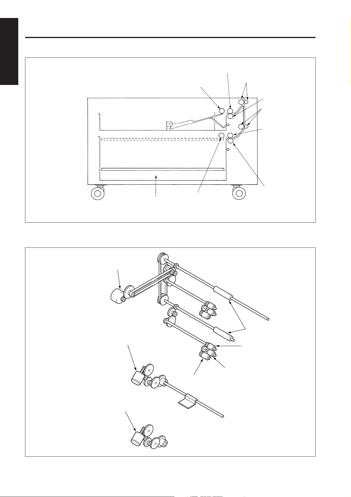
CENTER CROSS-SECTIONAL VIEW
1 OUTLINE
2
2 UNIT EXPLANATION
3 DIS./ASSEMBLY
Tray
DRIVE SYSTEM DIAGRAM
Paper feed roller
Paper feed roller
Separation roller
Conveyance rollers (upper)
Double-feed
prevention roller
Conveyance
rollers (lower)
Separation
roller
Double-feed
prevention roller
Paper feed motor (M401)
Up/down motor (PFU) (M402)
Up/down motor (LCT) (M403)
Intermediate
conveyance rollers
Separation roller
Double-feed prevention roller
Paper feed roller
1-2
Page 9

2
UNIT EXPLANATION
1 MAIN BODY
2 UNIT EXPLANATION
3 DIS./ASSEMBLY
Page 10

1 MAIN BODY
2
2 UNIT EXPLANATION
3 DIS./ASSEMBLY
Blank page
Page 11

500-SHEET PAPER TRAY UNIT
DB-608
[1] Composition
Paper feed roller
Separation roller
Guide release lever
Double-feed
prevention roller
Front cover
1 MAIN BODY
2 UNIT EXPLANATION
Intermediate
conveyance rollers
Paper feed door
Paper feed trays
3 DIS./ASSEMBLY
Rear edge stopper
Paper feed tray
[2] Mechanisms
Mechanisms
Paper feed
Paper lifting
Double-feed prevention
1st paper feed
Intermediate conveyance
Paper jam handling
No-paper detection
Paper size detection
Paper conveyance
Conveyance drive
Side guide
Method
Paper feed roller
Paper lift-up plate
Torque limiter
Separation roller, paper
feed SD
Intermediate conveyance
roller
Double-feed prevention
roller pressure release
Photosensor
Tact switch
Roller conveyance
Timing belt
2-1
Page 12

DB-608
[3] 500-Sheet Paper Feed Tray and No-Paper Detection Control
1 MAIN BODY
2
24VDC(DCPS1)
PGND(DCPS1)
5VDC(SCDB)
SGND(SCDB)
DB MTXD(SCDB)
(SCDB)
(SCDB)
DB SACK(SCDB)
(PRDB)
2 UNIT EXPLANATION
MAIN BODY
PS402
3 DIS./ASSEMBLY
Paper is fed by the drive force of M401 (paper feed) to
each paper feed roller and each feed roller through SD401
(paper feed (PFU)).
The M401 and SD401 are driven by the PFUDB (PFU)
(PFU drive board (PFU)) and controlled by the PFUDB
(PFU) in the main body.
DB MACK
DB SRXD
MPS DATA
5VDC
SGND
PS402
M401 CONT
M401 CLK
M401 H/L
24VDC
M401 CW/CCW
PGND
SGND
5VDC
PS401
24VDC
SD401 DRIVE
PFUDB(PFU)
1. Operation
a. Operation when copying
Paper feed for the first sheet starts a specified time
after the start button is turned ON. The paper feed
operation starts when the M401 and SD401 turn ON.
The M401 turns OFF a specified time after the PS401
(paper feed detect) detects the leading edge of the
page. SD401 turns OFF a specified time after turning
ON.
Paper feed for the second and subsequent sheets
starts a specified time after the SD401 for the
previouspage turns ON.
When the paper tray is empty, PS402 (no paper
detect (PFU)) changes to a high signal (L), to inform
the PFUDB (PFU) in the main body that there is no
paper in the tray.
M401
PS401
SD401
2-2
Page 13

DB-608
2. Signals
a. Input signals
(1) PS401 (PS401 to PFUDB (PFU))
This signal is output when PS401 (paper feed detect)
detects paper passing through the paper conveyance
section. It changes to an [H] signal when paper is
detected.
(2) PS402 (PS402 to PFUDB (PFU))
This signal is a no-paper detecting signal for the PFU.
[L]: When there is no paper in the tray
[H]: When there is paper in the tray
(3) DB MTXD (MAIN BODY to PFUDB (PFU))
The serial data line informs main body of DB
operation.
(4) DB SACK (MAIN BODY to PFUDB (PFU))
This signal is the transmission approved signal from
the main body to the DB.
b. Output signals
(1) M401 CONT (PFUDB (PFU) to M401)
This is the ON/OFF control signal for M401 (paper
feed).
[L]: M401 ON
[H]: M401 OFF
(2) M401 CLK (PFUDB (PFU) to M401)
This is the reference clock signal for M401 rotation
speed control.
(3) M401 H/L (PFUDB (PFU) to M401)
This is the signal for rotation speed control for M401.
[L]: High speed
[H]: Low speed
(4) M401 CW/CCW (PFUDB (PFU) to M401)
This is the signal for rotation direction control for
M401.
[L]: Forward direction
[H]: Reverse direction
(5) SD401 DRIVE (PFUDB (PFU) to SD401)
This is the ON/OFF control signal for SD401 (paper
feed (PFU)).
[L]: ON
[H]: OFF
1 MAIN BODY
2 UNIT EXPLANATION
3 DIS./ASSEMBLY
(6) DB SRXD (PFUDB (PFU) to MAIN BODY)
The serial data line informs DB of main body
operation.
(7) DB MACK (PFUDB (PFU) to MAIN BODY)
This signal is the transmission approved signal from
the main body to the DB.
(8) MPS DATA (PFUDB (PFU) to MAIN BODY)
This signal feeds the PS401 detecting signal back to
the main body.
2-3
Page 14

DB-608
[4] Tray-Up Control (PFU)
1 MAIN BODY
2
2 UNIT EXPLANATION
The paper tray is raised by transmitting the M402 (up/
down) driving force to the paper lifting lever.
The M402 is driven by the PFUDB (PFU) (PFU drive board
3 DIS./ASSEMBLY
(PFU)) and controlled by the PFUDB (U) in the main body.
24VDC (DCPS1)
PGND (DCPS1)
5VDC (DCPS1)
(SCDB)
DB MTXD(SCDB)
(SCDB)
(SCDB)
DB SACK(SCDB)
MAIN BODY
DB MACK
DB SRXD
24VDC
M402 DRIVE
5VDC
SGND
PS403
PFUDB(UPPER)
M402
PS403
SW401
SW402
SW403
SW404
2. Signals
a. Input signals
(1) PS403 (PS403 to PFUDB (PFU))
Upper limit-detecting signal on PFU.
The signal is at [H] level when the upper limit of paper
is detected.
b. Output signals
(1) M402 DRIVE (PFUDB (PFU) to M402)
This is the ON/OFF control signal for M402.
[L]: ON
[H]: OFF
1. Operation
The tray is raised when the M402 turns ON after the
SW401, 402, 403 or 404 (paper size-detect) turn ON.
After the tray is raised, the PS403 (upper limit
detect (PFU)) detects the upper limit of the paper in
the tray. The M402 turns OFF and the tray stops.
When paper is fed the PS403 turns ON and the tray is
raised when the M402 turns ON again.
The paper tray is lowered mechanically.
2-4
Page 15

DB-608
[5] Paper Size Detection Control
24VDC(DCPS1)
PGND(DCPS1)
5VDC(SCDB)
SGND(SCDB)
DB MTXD(SCDB)
(SCDB)
(SCDB)
DB SACK(SCDB)
DB MACK
DB SRXD
MAIN BODY
The PFUDB (PFU) (PFU drive board (PFU)) is fitted with a
series of tact switches for detecting paper size. This
informs the main body of the paper size in each tray.
1. Operation
Each tray has a series of actuators that are operated
by the paper guides. When each tray is inserted,
these projections turn the tact switches on the
PFUDB (PFU) OFF and ON. The PFUDB (PFU)
determines the paper size of the PFU from the ON/
OFF combinations.
PAPER SIZE DETECT
SWITCH
PFUDB(UPPER)
1 MAIN BODY
2 UNIT EXPLANATION
3 DIS./ASSEMBLY
2-5
Page 16

DB-608
1500-SHEET PAPER TRAY UNIT
[1] Composition
1 MAIN BODY
2
Rear edge stopper
2 UNIT EXPLANATION
3 DIS./ASSEMBLY
[2] Mechanism
Mechanisms
Paper stack
Paper lifting *1
Tray loading
*1: Paper lifting
Tray
Front cover
Method
Tray 1
Wire driven
Front loading
Side guide
Wire B
Drive AUX spring
Wire A
AUX wire
Wire D
Wire C
Drive pulley
Up/down motor
Coupling gear
The paper tray (LCT) is suspended using four Up/
Down drive wires (A, B, C and D).
When paper is loaded into the tray, the tray moves
down due to the weight of the paper. The weight of
the paper is balanced by the tension of the drive
auxiliary spring.
When the paper tray (LCT) is inserted, the up/down
motor (M403) rotates, winding the wires on the drive
reel and raising the tray.
When the paper tray is withdrawn from the frame, the
tray drive section and the coupling separate from
each other. This causes the tray to move down to the
position where the paper is balanced by the tension
of the drive auxiliary spring.
2-6
Page 17

DB-608
[3] 1500-Sheet Paper Feed Tray and No-Paper Detection Control
24VDC(DCPS1)
PGND(DCPS1)
5VDC(SCDB)
SGND(SCDB)
DB MTXD(SCDB)
(SCDB)
(SCDB)
DB SACK(SCDB)
(PRDB)
MAIN BODY
PS404
DB MACK
DB SRXD
MPS DATA
SD402 DRIVE
PS404
5VDC
SGND
PS404
M401 CONT
M401 CLK
M401 H/L
M401 CW/CCW
PFUDB(PFU)
SD402 DRIVE
PFUDB(LCT)
24VDC
PGND
SGND
5VDC
PS401
24VDC
24VDC
M401
PS401
SD402
1 MAIN BODY
2 UNIT EXPLANATION
3 DIS./ASSEMBLY
Paper is fed by transmitting the M401 (paper feed) driving
force to the paper feed roller and feed roller through
SD402 (paper feed (LCT)).
M401 is driven by the PFUDB (PFU drive board (PFU))
and controlled by the paper feed drive board PFUDB
(PFU) in the main body.
SD402 is driven by the PFUDB (PFU drive board (LCT))
and controlled by the PFUDB (PFU).
1. Operation
a. Initial operation when the power is switched ON
(1) When the power is switched ON, M401 goes ON for the
specified period.
Reason: This is to prevent the paper from being fed from
all of the paper trays at the same time when the
Start button is pressed, as a result of the the
ratchet claw of SD402 being disengaged due to
an impact when the machine was being
transported.
b. Operation when copying
Paper feed for the first sheet starts a specified time
after the start button is turned ON. The paper feed
operation starts when the M401 and SD402 turn ON.
The M401 turns OFF a specified time after the PS401
(paper feed detect) detects the leading edge of the
page. SD402 turns OFF a specified time after turning
ON.
Paper feed for the second and subsequent sheets
starts specified time after the SD402 for the previous
page turns ON.
When the paper tray is empty, PS404 (no paper
detect (LCT)) changes to a high signal (L), to inform
the PFUDB (PFU) in the main body that there is no
paper in the tray.
2-7
Page 18

DB-608
2. Signals
1 MAIN BODY
a. Input signals
(1) PS401 (PS401 to PFUDB (PFU))
2
(2) PS404 (PS404 to PFUDB (LCT) to PFUDB (PFU))
2 UNIT EXPLANATION
3 DIS./ASSEMBLY
This signal is output when PS401 (no paper detect)
detects paper passing through the paper conveyance
section. It changes to an [H] signal when paper is
detected.
This signal is a no-paper detecting signal for the LCT.
[L]: When there is no paper in the tray
[H]: When there is paper in the tray
b. Output signals
(1) M401 CONT (PFUDB (PFU) to M401)
This is the ON/OFF control signal for M401 (paper
feed).
[L]: M401 ON
[H]: M401 OFF
(2) M401 CLK (PFUDB (PFU) to M401)
This is the reference clock signal for rotation speed
control for M401.
(3) M401 H/L (PFUDB (PFU) to M401)
This is the signal for rotation speed control for M401.
[L]: High speed
[H]: Low speed
(4) M401 CW/CCW (PFUDB (PFU) to M401)
This is the signal for rotation direction control for
M401.
[L]: Forward direction
[H]: Reverse direction
(5) SD402 DRIVE (PFUDB (PFU) to PFUDB (LCT) t o SD402)
This is the ON/OFF control signal for SD402 (paper
feed (LCT)).
[L]: ON
[H]: OFF
(6) MPS DATA (PFUDB (PFU) to MAIN BODY)
This signal feeds the PS401 detecting signal back to
the main body.
2-8
Page 19

DB-608
[4] Tray-Up Control (LCT)
24VDC(DCPS1)
PGND(DCPS1)
5VDC(SCDB)
SGND(SCDB)
DB MTXD(SCDB)
(SCDB)
(SCDB)
DB SACK(SCDB)
MAIN BODY
DB MACK
DB SRXD
M403 DRIVE
5VDC
SGND
24VDC
PS405
PFUDB(PFU)
5VDC
SGND
PS405
M403
PS405
2. Signals
a. Input signals
(1) PS405 (PS405 to PFUDB (LCT) to PFUDB (PFU))
Upper limit-detecting signal for paper in the LCT.
The signal is [H] when the upper limit of the paper is
detected.
b. Output signals
(1) M403 DRIVE (PFUDB (PFU) to PFUDB (LCT) to M403)
This is the ON/OFF control signal for M403.
[L]: ON
[H]: OFF
1 MAIN BODY
2 UNIT EXPLANATION
3 DIS./ASSEMBLY
PFUDB(LCT)
SW405
The paper tray is raised when the M403 (up/down (LCT))
driving force is transmitted to the paper tray through the
up/down drive wires (four for each tray).
The M403 is driven by the PFUDB (LCT) (PFU detection
board (LCT)) and controlled by the PFUDB (PFU) (PFU
drive board (PFU)).
1. Operation
When the SW405 (LCT tray insertion detection) turns
ON, the M403 turns ON and raises the tray.
After the tray is raised, the PS405 (upper limit detect
(LCT)) detects the upper limit of the paper in the tray.
The M403 turns OFF and the tray stops.
When paper is fed the PS405 turns OFF and the tray
is raised when the M402 (up/down) turns ON again.
The paper tray is lowered mechanically.
2-9
Page 20

1 MAIN BODY
2
2 UNIT EXPLANATION
3 DIS./ASSEMBLY
Blank page
Page 21

3
DISASSEMBLY/ASSEMBLY
1 MAIN BODY
2 UNIT EXPLANATION
3 DIS./ASSEMBLY
Page 22

1 MAIN BODY
2
2 UNIT EXPLANATION
3 DIS./ASSEMBLY
This section covers the structure, functions, operation and method of
disassembling and assembling the machine.
Observe the following precautions when performing disassembly and
assembly work.
1. Be sure to unplug the power cord before working on the machine.
2. Perform all reassembly work by reversing the order in which the
componet was disassembled, unless otherwise specified.
3. Do not lose small parts (screws, etc.) or insert them in the wrong
place.
4. Install all parts completely before operating the machine.
5. Do not loosen the screws indicated as disallowed for removal.
Page 23

DISASSEMBLY AND REASSEMBLY
DB-608
CAUTION: Ensure the power cord is unplugged
from the socket.
[1] Removing and Reinstalling the Paper
Feed Tray
a. Procedure
(1) Pull out the paper feed tray and remove the two screws
on the left and the two screws on the right.
(2) Remove the paper feed tray from the guide rail.
Set screws
Paper
feed tray
(3) To reinstall the paper feed tray, reverse the procedure
above.
Set screws
Guide rail
[2] Removing and Reinstalling the Paper
Feed Unit
a. Procedure
(1) Pull out the paper tray towards you.
(2) Remove the two set screws, then remove the tray
stopper.
Tray stopper
Set screws
(3) Remove the set screw, then pull forward and remove
the paper feed unit, using the guide rail as a guide.
To remove the upper paper feed unit, remove the set
screw, then pull out the unit in the direction of arrow .
1 MAIN BODY
2 UNIT EXPLANATION
3 DIS./ASSEMBLY
Paper feed unit
Set scerw
Guide rail
(4) Reinstall the paper feed unit by reversing the procedure
above.
Caution: After installing the paper feed unit, take a
copy to check that the copier is operating
correctly. There is a possibility the paper
will not feed if the rocking gear and paper
feed SD are not in their correct positions.
3-1
Page 24

DB-608
[3] Replacing the Separation Rubber
1 MAIN BODY
2
a. Procedure
(1) Remove the paper feed unit.
(2) Remove the stop ring and shaft holder.
(3) While pulling out the paper feed shaft, remove the
2 UNIT EXPLANATION
3 DIS./ASSEMBLY
and the Paper Supply Rubber
separation roller from the paper feed roller unit.
Paper
feed shaft
Separation
roller
Separation
rubber
Marking
(7) To reinstall, reverse the above procedure.
Note 1: Make sure each roller rubber is installed in
the correct direction.
Note 2: Reinstall the rubber so that the rocking shaft
fits inside the paper feed roller unit.
Shaft
Rocking
shaft
(4) Remove the stop ring and, pulling the guide shaft in the
direction of the arrow, remove the paper feed roller.
Guide shaft
(5) Remove the separation rubber from the separation
roller.
(6) Remove the paper supply rubber from the paper feed
roller.
Paper feed
roller unit
Paper supply rubber
bushing
Stop ring
Paper feed roller
Stop ring
3-2
Page 25

DB-608
[4] Removing and Reinstalling the
Double-Feed Prevention Roller
a. Procedure
(1) Remove the paper feed unit.
(2) Remove the double-feed pressure spring.
(3) While pressing the shaft in the direction of the arrow,
remove the double-feed prevention unit from the paper
feed unit.
Double-feed
prevention unit
Double-feed
prevention spring
Shaft
1 MAIN BODY
2 UNIT EXPLANATION
3 DIS./ASSEMBLY
(4) Remove the stop ring, then while pushing the projection
on the lever click shaft, pull out the lever click shaft and
remove the double feed prevention roller.
Double-feed
prevention roller
Stop ring
Double-feed
prevention unit
(5) Reinstall the double-feed prevention roller by reversing
the procedure above.
Caution: After reinstallation, make sure that the
double-feed pressure spring moves the
double-feed prevention roller smoothly.
Lever click shaft
3-3
Page 26

DB-608
[5] Removing and Reinstalling the Paper
1 MAIN BODY
2
a. Procedure
(1) Slide out the paper tray and remove the two right and
(2) Remove the paper tray from the rails.
2 UNIT EXPLANATION
3 DIS./ASSEMBLY
(3) Reinstall the paper tray by reversing the procedure
Feed Tray (LCT)
two left screws.
Set screws
Paper tray (LCT)
above.
Set screws
[6] Removing and Reinstalling the Front
Tray Cover (LCT)
a. Procedure
(1) Remove the paper tray.
(2) Remove the five screws, then remove the front tray
cover.
Set screws
Front
Set screws
(3) Reinstall the front tray cover by reversing the procedure
above.
tray cover
3-4
Page 27

DB-608
[7] Replacing the Up/Down Wires
Caution 1: After replacing the up/down drive wires
or readjusting wire tension, move the
tray up and down to make sure that it
moves smoothly.
Caution 2: Be careful not to cross or overlap the
wires.
Removing the Up/Down Wires
2. Remove screw A.
3. Loosen screw B and rotate the tension fitting in a
clockwise direction.
4. Remove the AUX wire from the drive AUX spring.
Tension fitting
Set screw A
Drive AUX spring
Set screw B
AUX wire
Drive
AUX spring
Caution 3: After installing the up/down wires,
adjust the inclination of the tray.
Wire A: 513.9±0.4 mm
Wire B: 288.9±0.4 mm
Wire C: 305±0.4 mm
Wire D: 410.5±0.4 mm
AUX wire: 245.2±0.5 mm
Wire D
Wire A
Wire C
AUX wire
Wire B
1 MAIN BODY
2 UNIT EXPLANATION
3 DIS./ASSEMBLY
Set screw
1. Remove the wire protection covers.
Wire A
AUX wire
Drive pulley (front)
E-ring
5. Remove the E-ring, then remove the drive
pulley (front).
Wire B
Wire protection
cover
Front side
Drive pulley (rear)
6. Slide the drive shaft to the rear, remove the E-ring,
then slide the drive pulley (rear) to the front.
Set screw
E-ring
Wire C
Wire D
3-5
Page 28

DB-608
1 MAIN BODY
2
2 UNIT EXPLANATION
3 DIS./ASSEMBLY
<Installing the Up/Down Wires>
7. Connect the AUX wire to the drive AUX
spring.
8. Rotate the tension fitting in an anti-
clockwise direction and replace screw A.
9. Tighten screw B.
Tension fitting
Drive AUX
spring
2. Thread wires A and B through the
grooves in the pulley, then thread
them above the wire adjusting
material.
Wire A
1. Route the wire.
Wire B
3. Thread wires C and D through the
grooves in the pulley.
Wire C
Wire D
Screw A
Screw B
Wire A
AUX wire
Wire
protection
cover
Set screw
10. Replace the wire protection
cover.
AUX wire
Drive pulley
Wire B
5. Insert the AUX wire, wire A and
wire B into their respective holes
in the drive shaft, slide the drive
pulley onto the drive shaft, then
secure with the E-ring.
Wire A
AUX wire
6. Wind the AUX wire five turns
clockwise onto the drive pulley.
4. Insert wires C and D into their respective
holes in the drive shaft, slide the drive
pulley onto the drive shaft, then secure
with the E-ring.
Wire C
Wire D
Drive pulley
Wire B
Wire
protection
cover
Set screw
11. Replace the wire protection
cover.
3-6
 Loading...