

Page 1

FS-109
SERVICE HANDBOOK
Sep. 2000
Ver. 1.0
KONICA CORPORATION
TECHNOLOGY SUPPORT CENTER
TOKYO JAPAN
Page 2

KONICA CORPORATION
COPYRIGHT ©2000
CN55YF1300
Page 3

CONTENTS
CONTENTS
SAFETY AND IMPORTANT WARNING ITEMS .............
Refer to the 7045 service handbook on page C-1
1. OUTLINE
FS-109 PRODUCT SPECIFICATIONS ..................1-1
CENTER CROSS-SECTIONAL VIEW ................... 1-3
DRIVE SYSTEM DIAGLAM ................................... 1-4
[1] Paper Conveyance System Drive .............. 1-4
[2] Stapler Unit System Drive ..........................1-4
2. UNIT EXPLANATION
EXTERNAL SECTION ........................................... 2-1
[1] Composition ............................................... 2-1
CONVEYANCE SECTION ..................................... 2-2
[1] Composition ............................................... 2-2
[2] Mechanisms ...............................................2-2
[3] Paper Feed Motor (M801) Control ............. 2-5
[4] Conveyance Drum (M807) Control ............ 2-6
[5] Tray Up/Down (M804) Control ................... 2-7
PAPER EXIT/STAPLER UNIT SECTION .............. 2-9
[1] Composition ............................................... 2-9
[2] Mechanisms ...............................................2-9
[3] Paper Alignment Control ..........................2-11
[4] Paper Exit (M805) Control ....................... 2-12
[5] Paper Stacking Control ............................ 2-13
[6] Stapler Movement (M806) Control ...........2-14
[7] Stapler Control ......................................... 2-14
OTHER CONTROL FUNCTIONS ........................ 2-16
[1] Power-on Operation ................................. 2-16
1 OUTLINE
2 UNIT EXPLANATION
3 DIS./ASSEMBLY
3. DISASSEMBLY/ASSEMBLY
DISASSEMBLY AND REASSEMBLY .................... 3-1
[1] Replacing the Tray 2/3 Paper Exit
Roller Unit .................................................. 3-1
[2] Raising and Lowering the Tray .................. 3-1
[3] Removing and Reinstalling Tray 2/3 .......... 3-2
[4] Removing and Reinstalling the External
Covers ........................................................ 3-2
[5] Removing and Reinstalling the Lift Wire .... 3-3
[6] Replacing the Stapler Cartridge .................3-5
[7] Removing and Reinstalling
the Stapler Unit .......................................... 3-5
Page 4

1 OUTLINE
2
2 UNIT EXPLANATION
3 DIS./ASSEMBLY
Blank page
Page 5

1
OUTLINE
1 OUTLINE
2 UNIT EXPLANATION
3 DIS./ASSEMBLY
Page 6

1 OUTLINE
2
2 UNIT EXPLANATION
3 DIS./ASSEMBLY
Blank page
Page 7
FS-109 PRODUCT SPECIFICATIONS
FS-109
1. Type
Type: Natural inverting type, Multi-
tray finisher
2. Functions
Kinds of
copy paper: Same as main body
Copy Paper
size: A3R, F4R, B4R, A4, A4R, B5
B5R, A5R, 8.5 x 11, 8.5 x
11R/11 x 17R/8.5 x 14R
Modes
Mode
Through mode
Offset mode
Staple mode
Sheet capacity
Tray
Through mode
Tray 1
Through mode
Tray 2,
Offset mode
Tray 3
Staple mode
: Available ✕ : Not available
Tray
Tray 1
Mode
●
✕
✕
Small sizes
100
300
–
25 sets (Note)
Middle sizes Large sizes
100
700
700
Tray 2
●
●
●
100
300
300
Tray 3
●
●
●
Special paper
10
–
–
–
Paper weight
Tray 1: 50 - 200 g/m
Tray 2/3: 60 - 130 g/m
2
2
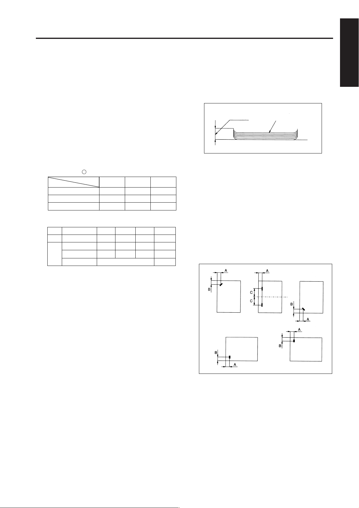
Copy paper
curling: 10 mm max.
Curling
Copy paper (5 sheets)
Offset amount: 30 mm (offset/group mode)
3. Stapler Kit
No. of
copies
stapled : 50 max. (80 g/m
thickness 5 mm max)
Staple
position: A = 8 mm (±3 mm adjustable)
B = 10 mm (±3 mm adjustable)
C = 90 mm (±4 mm adjustable)
Stapler
capacity: 5000 staples/cartridge
2
fine quality paper,
1 OUTLINE
2 UNIT EXPLANATION
3 DIS./ASSEMBLY
Note1: The above numbers apply for same-size
paper (80g/m
2
, standard paper) stacked
continuously.
Note2: Small sizes: A5R, B6R, 5.5 x 8.5R (For
B6R, only Tray 1 and the
through mode can be
used.)
Middle sizes: A4, A4R, B5, 8.5 x 11,
8.5 x 11R
Large sizes: A3R, F4R, B4R, B5R,
11 x 17R, 8.5 x 14R
Special paper: Other than standard paper
(thin paper, thick paper,
blueprint master
OHP film etc.)
Note3: The maximum capacity (500 or 300
sheets) should not be exceeded.
1-1
Page 8

1 OUTLINE
2
2 UNIT EXPLANATION
FS-109
4. Particulars of Machine
Power
source:
Max. power
consumption: 100 VA
Weight: Approx. 37 kg (with pedestal)
Machine
dimensions: Width 265mm
24 V DC / 5 V (supplied from main body)
Depth 599.2mm
Height 623.2mm
5. Maintenance and Life
Maintenance: Same as the main body
Service life: Same as the main body
6. Operating Environment
Temperature: 10°C to 30 °C
Humidity: 10% to 80% RH
Note: The contents of this manual may be changed
3 DIS./ASSEMBLY
without prior notice.
1-2
Page 9
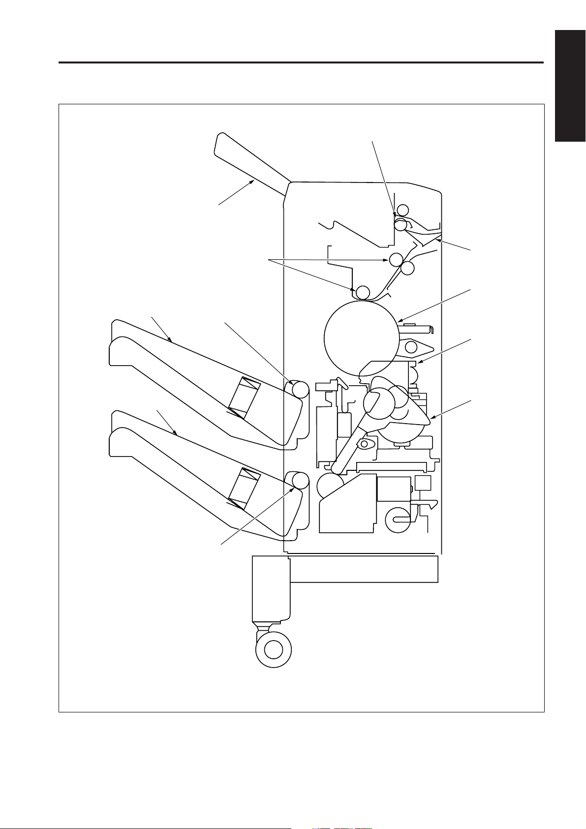
CENTER CROSS-SECTIONAL VIEW
Paper exit roller
Tray 1
FS-109
1 OUTLINE
Tray 2
Tray 3
Conveyance rollers
Switching gate
2 UNIT EXPLANATION
Conveyance drum
Paper exit roller (A)
Stapler unit
3 DIS./ASSEMBLY
Exit lever
Paper exit roller (A)
1-3
Page 10
FS-109
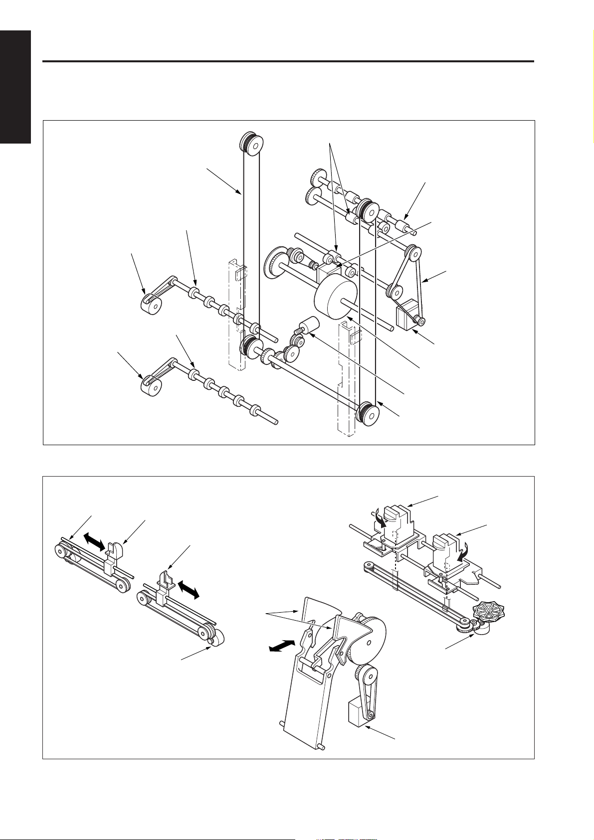
DRIVE SYSTEM DIAGRAM
[1] Paper Conveyance System Drive
1 OUTLINE
Conveyance rollers
2
2 UNIT EXPLANATION
3 DIS./ASSEMBLY
Tray 2 motor (M810)
Tray 3 motor (M811)
Lift wire (rear)
Paper exit roller (A)
Paper exit roller (A)
Paper exit roller
Conveyance
drum drive motor (M807)
Timing belt
Conveyance motor (M801)
Conveyance drum
Tray up/down motor (M804)
Lift wire (front)
[2] Stapler Unit System Drive
Alignment motor
(rear)(M808)
Alignment plate
(rear)
Alignment plate
(front)
Alignment motor
(front)(M809)
Stapler unit (rear)
Stapler unit (front)
Exit lever
Stapler movement
motor (M806)
Paper exit motor (M805)
1-4
Page 11

2
UNIT EXPLANATION
1 OUT LINE
2 UNIT EXPLANATION
3 DIS./ASSEMBLY
Page 12

1 OUT LINE
2
2 UNIT EXPLANATION
3 DIS./ASSEMBLY
Blank page
Page 13

EXTERNAL SECTION
FS-109
[1] Composition
Tray 2
Tray 1
Release lever
Tray 3
Front cover
1 OUT LINE
Top cover
Upper rear cover
2 UNIT EXPLANATION
Rear cover
3 DIS./ASSEMBLY
2-1
Page 14

1 OUT LINE
2
FS-109
CONVEYANCE SECTION
[1] Composition
Gate SD
2 UNIT EXPLANATION
Lift wire
3 DIS./ASSEMBLY
[2] Mechanisms
Mechanisms Methods
Paper path switching *1
Paper conveyance *2
Tray lift (up/down) *3
Conveyance motor
Switching gate
Conveyance roller
Conveyance drum
Wire drive (Lift wire)
Switching gate
Conveyance
drum motor
Conveyance
drum
Tray up/down
motor
Conveyance
drum
Lift wire
Switching gate
*1: Paper path switching
The paper exited from the fixing unit in the main body
passes through the switching gate which sends it to
tray 1 or tray 2/3. The switching gate is operated by
the on/off state of the gate SD (SD801).
Gate SD
2-2
Page 15

FS-109
*2: Paper Conveyance
When the paper has been switched to tray 2/3 by the
switching gate, the conveyance roller conveys it to
the conveyance drum until it enters the grip plate on
the circumference of the drum.
Switching
Conveyance
rollers
Grip plate
Spring
gate
Paper
Cam
Conveyance
drum
The grip plate closes due to the force of a cam and
spring arrangement and grasps the paper.
When the rotation speed of the drum increases, the
paper is pushed out and separated from the
conveyance drum. When the grip plate on the
conveyance drum reaches the paper exit position,
the paper hits a stopper and is separated from the
grip plate.
Paper
Stopper
Grip plate
Behind the grip plate on the drum circumference,
there are two alignment plates. When these reach the
paper exit position, their own weight causes them to
open, and the rubber section at the plate tip aligns the
paper against the stopper.
1 OUT LINE
2 UNIT EXPLANATION
Conveyance
drum
3 DIS./ASSEMBLY
Grip plate
Spring
Conveyance drum
Paper
Cam
Alignment plates
Conveyance
drum
Paper
Grip plate
Stopper
2-3
Page 16

FS-109
1 OUT LINE
2
2 UNIT EXPLANATION
3 DIS./ASSEMBLY
The grip plate and alignment plates on the
conveyance drum do not use electrical control, they
operate only through the rotation of the drum. (The
grip plate is driven by the drum via a cam
arrangement, and the alignment plates are driven by
the centrifugal force and their own weight.)
The conveyance drum and conveyance rollers are
controlled electrically by conveyance drum motor
(M807) and conveyance motor (M801).
*3: Tray lift
The paper exit position for the paper sent to tray 2/3
is fixed. Switching between tray 2 and tray 3 is carried
out by changing the tray position with the tray lift (up/
down) mechanism.
The tray lift mechanism is driven by the tray up/down
motor (M804) whose driving force is transmitted to the
tray by a wire arrangement.
Lift wire
Tray 2
Tray up/down motor
2-4
Tray 3
Page 17

FS-109
24V
0V
[3] Conveyance Motor (M801) Control
SD801
PS803
M801
PS802
MS801
SGND
SGND
PGND
PGND
PGND
M TxD
M REQ
M ACK
MAIN BODY
5V
5V
24V
24V
24V
24V
SD801 DRV
VCC
PS803IN
GND
24V
24V
M801 DRVA
M801 DRVA
M801 DRVB
M801 DRVB
VCC
PS802IN
GND
24VOUT
24VIN
S ACK
M RxD
S REQ
FNSCB
2. Signals
a. Input signals
(1) PS802IN (PS802 to FNSCB)
Paper detection signal at the paper exit section
entrance of the tray 2 and tray 3 side.
[L]: Paper is not detected
[H]: Paper is detected
(2) PS803IN (PS803 to FNSCB)
Paper detection signal at the paper exit section
entrance of the tray 1.
[L]: Paper is not detected
[H]: Paper is detected
(3) 24VIN (MS801 to FNSCB)
Power supply line for various loads. When finisher is
in mechanical contact with main body, 24 V DC is
supplied to finisher.
(4) M TxD (MAIN BODY to FNSCB)
Serial data line for transmitting operation status
information from control board in main body to
finisher.
(5) M REQ (MAIN BODY to FNSCB)
Send request signal from main body to finisher.
(6) M ACK (MAIN BODY to FNSCB)
Send enable signal from main body to finisher.
1 OUT LINE
2 UNIT EXPLANATION
3 DIS./ASSEMBLY
Paper exit conveyance takes place as a result of the
transmission of the drive force of motor M801
(conveyance) to the paper exit rollers and conveyance
rollers. The paper conveyance path is switched between
tray 1 or tray 2/3 by solenoid SD801 (gate).
M801 and SD801 are controlled by the FNSCB (FNS
control board).
1. Operation
a. Gate switching operation
Normally, SD801 is OFF and the gate allows paper to
exite to tray 2/3. When tray 1 is selected as the paper
exit tray, SD801 goes ON, the gate is switched, and
the paper is conveyed to tray 1.
b. Conveyance operation
M801 is turned ON and OFF in conjunction with the
copy operation of the main body. During operation of
the main body, the M801 rotates constantly, enabling
paper conveyance at any time.
When paper has been conveyed to tray 2/3, the
status of the PS802 (drum entrance) and main body
PS1 (paper exit) causes the M801 to be switched
from low speed to high speed. The high-speed
activation signal and the rotation speed depend on
the paper size.
b. Output signals
(1) M801 DRV A, A, B, B (FNSCB to M801)
M801 ON/OFF drive signal
(2) SD801 DRV (FNSCB to SD801)
SD801 ON/OFF drive signal
[L]: SD801 ON
[H]: SD801 OFF
(3) M RxD (FNSCB to MAIN BODY)
Serial data line for transmitting operation status
information from finisher to main body CB (control board).
(4) S REQ (FNSCB to MAIN BODY)
Send request signal from finisher to main body.
(5) S ACK (FNSCB to MAIN BODY)
Send enable signal from finisher to main body.
2-5
Page 18

FS-109
1 OUT LINE
2
2 UNIT EXPLANATION
3 DIS./ASSEMBLY
[4] Conveyance Drum (M807) Control
PS801
PS802
M807
SGND
SGND
PGND
PGND
PGND
24V
24V
24V
M TxD
M REQ
M ACK
5V
5V
VCC
PS801IN
GND
VCC
PS802IN
GND
24V
24V
M807 DRVA
M807 DRVA
M807 DRVB
M807 DRVB
S ACK
M RxD
S REQ
2. Signals
a. Input signal
(1) PS801IN (PS801 to FNSCB)
Encoder slit detection signal
[L]: Slit is not detected
[H]: Slit is detected
b. Output signal
(1) M807 DRV A, A, B, B (FNSCB to M807)
M807 ON/OFF drive signal
24V
0V
MAIN BODY
FNSCB
The paper that has been sent to tray 2/3 is exited into the
respective tray by the conveyance drum. The conveyance
drum is driven by M807 (conveyance drum) which is
controlled by the FNSCB (FNS control board).
1. Operation
a. Conveyance operation
When PS802 (drum entrance) detects the leading
edge of the paper and goes ON, M807 is turned ON
after the specified time, and the conveyance drum
starts to rotate.
To convey one sheet of paper, the M807 is switched
through a predetermined sequence of three speeds.
When the conveyance drum reaches the standby
position, the motor is switched OFF.
During this time, the drum makes one revolution
which includes gripping, conveying, and releasing the
paper.
b. M807 speed control
When the conveyance drum rotation pulses reach a
predetermined number, the rotation speed is
changed.
2-6
Page 19

FS-109
[5] Tray Up/Down (M804) Control
24VOUT
MS802
MS803
24VIN
M804 DRV 1
SGND
SGND
PGND
PGND
PGND
M TxD
M REQ
M ACK
MAIN BODY
5V
5V
24V
24V
24V
S ACK
M RxD
S REQ
FNSCB
M804 DRV 2
VCC
PS805IN
GND
VCC
PS806IN
GND
The paper exit position of the conveyance drum is always
fixed, and tray switching is carried out by raising or
lowering tray 2/3.
The up/down motion is achieved by transmitting the
driving force of motor M804 (tray up/down) to the lift wires
connected to each tray. This operation is controlled by the
FNSCB (FNS control board).
M804
PS805
PS806
1. Operation
Normally, the paper exit position of the conveyance
drum is aligned with tray 2. Therefore no lift operation
is carried out when tray 2 is selected.
a. Upward movement
When tray 3 is selected as paper exit tray and PS806
(tray lower limit) is ON, M804 (tray up/down) goes ON
(forward rotation). Tray 2 and tray 3 are then raised
simultaneously.
When the upward movement causes tray 2 to switch
PS805 (tray upper limit) to ON, M804 goes OFF and
the upward movement stops. Tray 3 is now aligned
with the paper exit position of the conveyance drum.
b. Downward movement
When tray 2 is selected as paper exit tray and PS805
is ON, M804 goes ON (reverse rotation). Tray 2 and
tray 3 are then lowered simultaneously.
When the downward movement causes tray 3 to
switch PS806 to ON, M804 goes OFF and the
upward movement stops. Tray 2 is now aligned with
the paper exit position of the conveyance drum.
c. Tray squeeze prevention
During tray upward or downward movement, if a
foreign object is caught between the tray and the
finisher unit, MS802 (up/down (upper)) or MS803 (up/
down (lower)) will mechanically go OFF, causing the
power supply line of M804 to be cut off.
1 OUT LINE
2 UNIT EXPLANATION
3 DIS./ASSEMBLY
2-7
Page 20

1 OUT LINE
2
2 UNIT EXPLANATION
3 DIS./ASSEMBLY
FS-109
2. Signals
a. Input signals
(1) PS805IN (PS80 to FNSCB)
Tray 2 upper limit detection signal.
[L]: Upper limit is not detected
[H]: Upper limit is detected
(2) PS806IN (PS806 to FNSCB)
Tray 3 lower limit detection signal.
[L]: Lower limit is not detected
[H]: Lower limit is detected
(3) 24VIN (MS802/MS803 to FNSCB)
Power supply line for M804 (tray up/down). Forcibly
interrupted when a foreign object is caught between
tray and finisher unit.
b. Output signal
(1) M804 DRV 1, 2 (FNSCB to M804)
M804 drive signals.
M804 rotation direction is controlled by switching the
current direction of these two signals.
State M804 DRV 1 M804 DRV 2
Upward movement
Downward movement
Stop
L
L
H
L
H
H
2-8
Page 21

PAPER EXIT/STAPLER UNIT SECTION
FS-109
[1] Composition
Paper exit rollers (A)
Tray 2 motor
Tray 3 motor
Alignment plate (front)
Tray 2/3
Stapler unit (front)
Alignment motor (front)
Exit levers
Stapler movement motor
1 OUT LINE
Stopper
Stapler
unit (rear)
2 UNIT EXPLANATION
Paper exit motor
3 DIS./ASSEMBLY
[2] Mechanisms
Mechanisms Methods
Paper alignment *1
Paper exit *2
Paper stacking *3
Stapler unit movement
Staple accident prevention *4
*1: Paper alignment
The paper being conveyed by the conveyance drum
is aligned by the alignment plates. Separately driven
guides are provided for front and rear, to allow
independent movement and asymmetrical operation
in shift mode.
The alignment plates are driven by the alignment motor
(front) (M809) and alignment motor (rear) (M808).
Separate guides for front and rear
Exit lever
Paper exit roller (A)
Stapler unit movement motor
Shutter cover
Alignment motor (rear)
Alignment plate (rear)
Alignment plate (front)
Alignment motor (front)
2-9
Page 22

FS-109
1 OUT LINE
2
2 UNIT EXPLANATION
3 DIS./ASSEMBLY
*2: Paper exit
The paper being supplied by the conveyance drum is
conveyed to the stapling position, regardless of
whether stapling will be carried out or not. If stapling
is enabled, the stapled stack is exited to tray 2 or 3
after stapling. If stapling is not enabled, each sheet is
exited individually to tray 2 or 3.
This movement is performed by the exit levers which
are driven by the paper exit motor (M805).
Exit levers
Paper exit motor
Tray 2 motor
Tray 3 motor
Paper exit roller (A)
*4: Staple accident prevention
A shutter cover is provided to prevent the user from
inadvertently inserting a finger etc. into the stapler. The
shutter cover is driven by the shutter SD (SD802) which
is ON during stapler operation and during stapler unit
movement. The shutter cover blocks the clearance
between the paper exit tray and the stapler unit.
*3: Paper stacking
A spring arrangement in the bottom of tray 2 and tray
3 lifts the bottom plate up, so that it always is in direct
contact or not more than 3 mm away from the paper
exit roller assembly.
[ Operation in through mode ]
The paper is stacked on the tray by the movement of
the exit lever and the rotation of the paper exit roller
(A) of each tray.
When the paper exit roller (A) turns, the tip of the
paper is grasped by the rollers and is stacked under
the rollers.
[ Operation in offset mode ]
The paper is offset by the alignment plates (front/
rear), and is stacked on the tray by the movement of
the exit lever and the rotation of the paper exit roller
(A) of each tray.
By repeating this action, the tip of the paper is
grasped by the rollers and is stacked under the
rollers.
Tray 2
Shutter SD
Paper exit roller (A)
Conveyance
drum
Spring
Stapler
unit
Exit lever
Shutter
cover
2-10
Page 23

FS-109
24V
0V
24V
0V
[3] Paper Alignment Control
M808 DRV A
M808 DRV A
M808 DRV B
M808 DRV B
M809 DRV A
M809 DRV A
M809 DRV B
M809 DRV B
PS815IN
SGND
SGND
PGND
PGND
PGND
M TxD
M REQ
M ACK
MAIN BODY
5V
5V
24V
24V
24V
S ACK
M RxD
S REQ
FNSCB
PS816IN
PS802IN
PS804IN
24V
24V
24V
24V
5VDC
GND
5VDC
GND
5VDC
GND
5VDC
GND
M808
M809
PS815
PS816
PS802
PS804
b. Shift alignment operation
During the first alignment operation, the alignment
plate (front) and alignment plate (rear) are front and
rear symmetric with respect to operation as reference
with the center of the tray and paper is exited.
During the next alignment operation, the alignment
plate (front) and alignment plate (rear) are not front
and rear symmetric with respect to operation as
reference with the center of the tray and paper is
exited at the position shift to the first copy.
From now on, these operation are repeated.
The ON/OFF timing of M809 and M808 is the same
as that of the non-shift alignment operation.
c. Staple mode operation
In staple mode, M809 and M808 perform release
operation after stapling is completed. The ON/OFF
timing is based on the OFF timing of the stapler motor
that last completed a stapling operation (M802 or M803).
2. Signals
a. Input signals
(1) PS815IN (PS815 to FNSCB)
Home position detection signal for alignment plate (front).
[L]:Alignment plate is not in home position
[H]:Alignment plate is in home position
(2) PS816IN(PS816 to FNSCB)
Home position detection signal for alignment plate (rear).
[L]:Alignment plate is not in home position
[H]:Alignment plate is in home position
1 OUT LINE
2 UNIT EXPLANATION
3 DIS./ASSEMBLY
The paper exited by the conveyance drum is aligned on
the center of the respective exit tray by the alignment
plates driven by the M808 (alignment (rear)) and M809
(alignment (front)). M808 and M809 are controlled by the
FNSCB (FNS control board).
1. Operation
a. Non-shift alignment operation
The alignment plate (front) and alignment plate (rear)
work symmetrically, with the tray center serving as
the reference point. The guides repeat the alignment
and release pattern. The rotation direction of M809
and M808 is therefore always opposite.
The ON timing of M809 and M808 is referenced to the
ON/OFF state of PS802 (drum entrance) or PS804
(paper through detect). Which sensor is used
depends on the paper size.
b. Output signals
(1) M808 DRV A, A, B, B (FNSCB to M808)
M808 ON/OFF drive signal
(2) M809 DRV A, A, B, B (FNSCB to M809)
M809 ON/OFF drive signal
2-11
Page 24

FS-109
1 OUT LINE
2
2 UNIT EXPLANATION
3 DIS./ASSEMBLY
[4] Paper Exit (M805) Control
24V
24V
M805 DRV A
M805 DRV A
M805 DRV B
SGND
SGND
PGND
PGND
PGND
M TxD
M REQ
M ACK
MAIN BODY
5V
5V
24V
24V
24V
S ACK
M RxD
S REQ
FNSCB
M805 DRV B
VCC
PS813IN
GND
VCC
PS804IN
GND
When the alignment or stapling operation is completed, the
paper is pushed out to tray 2 or tray 3 by the exit levers. The
levers are driven by M805 (paper exit) via a set of gears.
Operation is controlled by the FNSCB (FNS control board).
M805
PS813
PS804
2. Signals
a. Input signal
(1) PS813IN (PS813 to FNSCB)
Home position detection signal for exit lever.
[L]: Exit lever is not in home position
[H]: Exit lever is in home position
b. Output signal
(1) M805 DRIVE A, A, B, B (FNSCB to M805)
M805 ON/OFF drive signal
24V
0V
1. Operation
a. Non-stapling mode operation
The drive gear for the exit levers is controlled using
the home position detected by PS813 (paper exit
motor HP).
When PS804 (paper through) detects the paper
leading edge and goes ON, M805 goes ON for the
specified time and drives the exit levers. This causes
PS813 to go OFF.
The exit levers are connected to the circumference of
the drive gear. Within one rotation of the gear, the
paper is pushed out (forwarding motion) and returned
to the standby position (return motion).
When PS813 goes ON, the exit levers have returned
to the standby position and M805 is turned OFF.
b. Stapling mode operation
In stapling mode, when the stapler motor (M802 or
M803) that has last finished to operate goes OFF,
M805 goes ON for the specified time and drives the
exit levers. Other operations are the same as for nonstapling mode.
2-12
Page 25

FS-109
24V
0V
24V
0V
[5] Paper Stacking Control
M810 DRV A
M810 DRV A
M810 DRV B
M810 DRV B
M811 DRV A
M811 DRV A
M811 DRV B
SGND
SGND
PGND
PGND
PGND
M TxD
M REQ
M ACK
MAIN BODY
5V
5V
24V
24V
24V
S ACK
M RxD
S REQ
FNSCB
M811 DRV B
24V
24V
24V
24V
VCC
PS807IN
GND
VCC
PS809IN
GND
M810
M811
PS807
PS809
b. Tray auto-switching control
When copying is carried out with tray 2 or tray 3
specified as output tray and the specified tray
becomes full, causing PS807 or PS809 to become
ON, the output tray is automatically switched to the
other tray.
This operation is also valid if tray 1 is specified as the
output tray. The output tray will be switched to tray 2
or tray 3. Normally, tray 2 will be selected. If it is full,
tray 3 will be selected. Switching from tray 2 or tray 3
to tray 1 is not possible.
2. Signals
a. Input signals
(1) PS807IN (PS807 to FNSCB)
Tray 2 stack-full detection signal
[L]: Stack full condition not detected
[H]: Stack full condition detected
(2) PS809IN (PS809 to FNSCB)
Tray 3 stack-full detection signal
[L]: Stack full condition not detected
[H]: Stack full condition detected
b. Output signals
(1) M810 DRV A, A, B, B (FNSCB to M810)
M810 ON/OFF drive signal
1 OUT LINE
2 UNIT EXPLANATION
3 DIS./ASSEMBLY
The paper exited to tray 2 or tray 3 is placed on top of the
paper exit rollers of the respective tray. The drive force of
motor M810 (tray 2) or M811 (tray 3) is used to operate the
rollers and stack the paper on the tray.
M810 and M811 operation is controlled by the FNSCB
(FNS control board).
1. Operation
a. Paper stacking control
When M805 (paper exit) goes ON, M810 (tray 2) or
M811 (tray 3) are set to ON after the specified time.
When M805 goes OFF, M810 or M811 are set to OFF
after the specified time. While the motor is ON, the
rollers of the tray are driven and the paper that was
placed on the rollers is stacked.
The stacking section of the tray is pushed up by a
spring. When the maximum allowable number of sheets
has been stacked, the stacking section contacts the
bottom of the tray and PS807 (tray 2 full-stack detect) or
PS809 (tray 3 full-stack detect) goes ON.
When PS807 or PS809 are ON, no copy operation
will be carried out when the respective tray is
selected.
(2) M811 DRV A, A, B, B (FNSCB to M811)
M811 ON/OFF drive signal
2-13
Page 26

FS-109
1 OUT LINE
2
2 UNIT EXPLANATION
3 DIS./ASSEMBLY
[6] Stapler Movement (M806) Control
24V
24V
M806 DRV A
M806 DRV A
M806 DRV B
SGND
SGND
PGND
PGND
PGND
M TxD
M REQ
M ACK
MAIN BODY
5V
5V
24V
24V
24V
S ACK
M RxD
S REQ
FNSCB
M806 DRV B
VCC
PS814IN
GND
24V
24VIN
The position of the stapler units at the front and rear with
respect to the paper is adjusted using the driving force of
the M806(stapler movement). Operation of M806 is
controlled by the FNSCB (FNS control board).
1. Operation
Normally, the stapler units are stationary, positioned so
that the stapling is carried out parallel to the paper edge.
This position is detected by PS814 (stapler unit HP).
When the stapling position is changed according to a
command from the main body, M806 goes ON and
the two stapler units at the front and rear are moved
simultaneously. The M806 OFF timing is controlled
using the number of drive step from when PS814
went OFF.
2. Signals
a. Input signals
(1) PS814IN (PS814 to FNSCB)
Home position detection signal for stapler unit
[L]: Stapler unit is in home position
[H]: Stapler unit is not in home position
M806
PS814
MS804
[7] Stapler Control
M802 DRV 1
M802 DRV 2
VCC
PS820IN
PS821IN
PS822IN
GND
M803 DRV 1
M803 DRV 2
VCC
PS817IN
PS818IN
PS819IN
GND
SGND
SGND
PGND
PGND
PGND
M TxD
M REQ
M ACK
MAIN BODY
5V
5V
24V
24V
24V
S ACK
M RxD
S REQ
FNSCB
24VOUT
24VIN
24V
SD802 DRV
Stapling is carried out by driving M802 (stapler (rear)) and
M803 (stapler (front)). Operation of M802 and M803 is
controlled by the FNSCB (FNS control board).
The maximum number of sheets for stapling and the
operation to be carried out when the number is exceeded
can be set with 25 mode of the main body. For details,
refer to the adjustment section of the main body
M802
M803
MS804
SD802
(2) 24VIN (MS804 to FNSCB)
Power supply line for M802 (stapler (rear)), M803
(stapler (front)), and M806. Forcibly interrupted when
the shutter is raised.
b. Output signal
(1) M806 DRV A, A, B, B (FNSCB to M806)
M806 ON/OFF drive signal
24V
0V
2-14
Page 27

FS-109
1. Operation
a. Stapling operation
M803 (stapler (front)) goes ON when the last paper
alignment operation is completed, and goes OFF
when PS817 (stapler HP (front)) goes ON.
This causes the front side of the paper to be stapled.
When stapling at two locations is carried out, M802
(stapler (rear)) goes ON after the specified time,
measured from the point when M803 goes ON. It
goes OFF when PS820 (stapler HP (rear)) goes ON.
b. Shutter control
During stapler unit movement and during stapling
operation, the SD802 (shutter) is ON, causing the
shutter to block the clearance between the paper exit
tray and the stapler unit.
c. No-staple detection
The front and rear stapler units are each equipped
with a PS818, PS821 (no stapler (front), (rear)).
When staples have run out and the no staple
condition is detected, a message is shown on the
display of the main body.
2. Signals
a. Input signals
(1) PS817IN (stapler unit (front) to FNSCB)
Home position detection signal for M803
[L]: Home position is detected
[H]: Home position is not detected
(2) PS818IN (stapler unit (front) to FNSCB)
Stapler unit (front) no-staple detection signal.
[L]: No-staple condition is detected
[H]: No-staple condition is not detected
(3) PS820IN (stapler unit (rear) to FNSCB)
Home position detection signal for M802
[L]: Home position is detected
[H]: Home position is not detected
(4) PS821IN (stapler unit (rear) to FNSCB)
Stapler unit (rear) no-staple detection sensor signal
[L]: No-staple condition is detected
[H]: No-staple condition is not detected
(5) PS819IN (stapler unit (front) to FNSCB)
[L]: stapler unit (front) tion is detected
[H]: No-staple condition is not detected
(6) PS822IN (stapler unit (rear) to FNSCB)
stapler unit (rear) no-staple sensor signal at the
stapling position.
[L]: No-staple condition is detected
[H]: No-staple condition is not detected
1 OUT LINE
2 UNIT EXPLANATION
3 DIS./ASSEMBLY
b. Output signals
(1) M802 DRV 1, 2 (FNSCB to stapler unit (rear))
M802 drive signals.
M802 rotation direction is controlled by switching the
current direction of these two signals.
(2) M803 DRV 1, 2 (FNSCB to stapler unit (front))
M803 drive signals.
M803 rotation direction is controlled by switching the
current direction of these two signals.
(3) SD802 DRV (FNSCB to SD802)
SD802 ON/OFF drive signal.
[L]: SD802 ON
[H]: SD802 OFF
2-15
Page 28

1 OUT LINE
2
2 UNIT EXPLANATION
FS-109
OTHER CONTROL FUNCTIONS
[1] Power-on Operation
When the main body SW2 (sub power) is set to ON,
the finisher performs the following initialization
sequence.
1. SD802 (shutter) goes ON and the shutter cover closes.
2. M808 (alignment (rear)) and M809 (alignment (front))
go ON and the alignment plates (front/rear) perform
home position search.
3. M807 (conveyance drum) goes ON and the conveyance drum performs home position search.
4. M806 (stapler movement) goes ON and the stapler unit
moves to the standby position.
5. SD802 goes OFF and the shutter cover opens.
6. M805 (paper exit) goes ON and the exit lever is driven
for one operation.
7. Lower limit position detection for tray 2 and tray 3 is
carried out. If PS806 (tray lower limit) does not go ON,
M804 (tray up/down) goes ON, causing tray 2 and tray
3 DIS./ASSEMBLY
3 to move downward.
2-16
Page 29

3
DISASSEMBLY/ASSEMBLY
1 OUT LINE
2 UNIT EXPLANATION
3 DIS./ASSEMBLY
Page 30

1 OUT LINE
2
2 UNIT EXPLANATION
3 DIS./ASSEMBLY
This section covers the structure, functions, operation and method of
disassembling and assembling the machine.
Observe the following precautions when performing disassembly and
assembly work.
1. Be sure to unplug the power cord before working on the machine.
2. Perform all reassembly work by reversing the order in which the
componet was disassembled, unless otherwise specified.
3. Do not lose small parts (screws, etc.) or insert them in the wrong
place.
4. Install all parts completely before operating the machine.
5. Do not loosen the screws indicated as disallowed for removal.
Page 31

DISASSEMBLY AND REASSEMBLY
FS-109
Caution: Be sure that the power cord of the
main body is unplugged from the
power outlet.
[1] Replacing the Tray 2/3 Paper Exit
Roller Unit
Before replacing the paper exit roller unit for tray 3,
move tray 2 to the top. (See 2. "Raising and
Lowering the Tray".)
a. Procedure
(1) Remove the two set screws, and remove the connector
cover.
Set screws
Connector cover
[2] Raising and Lowering the Tray
a. Raising procedure
(1) Start the main body in the 47 mode while referring to the
main body manual (Field Service volume).
(2) Enter the following codes.
Input/output check code: 70
Multi code: 16
Note: Finalize each entered code by pressing
the P button
(3) Press the Start button, and the tray starts to rise. When
the tray reaches the position at which you wish to stop
it, press the Stop/Clear button.
b. Lowering procedure
(1) Start the main body in the 47 mode while referring to
main body manual (Field Service volume).
(2) Enter the following codes.
Input/output check code: 70
Multi code: 15
Note: Finalize each entered code by pressing
the P button.
(3) Press the Start button, and the tray starts to fall. When
the tray reaches the position at which you wish to stop
it, press the Stop/Clear button.
1 OUT LINE
2 UNIT EXPLANATION
3 DIS./ASSEMBLY
(2) Remove the left and right stop rings and bearings, then
remove the paper exit roller unit.
Stop ring
Paper exit roller unit
Bearing
(3) Install the new roller unit in the opposite sequence to
removal.
Stop ring
Bearing
3-1
Page 32

FS-109
1 OUT LINE
2
2 UNIT EXPLANATION
3 DIS./ASSEMBLY
[3] Removing and Reinstalling Tray 2/3
a. Procedure
(1) Remove the two set screws, and remove the connector
cover.
(2) Disconnect the two connectors (CN728 and 751: Tray
2 / CN729 and 752: Tray 3).
(3) Remove the set screw, and remove the stopper.
Set screw
Stopper
Connector
(CN 728)
Connector
(CN 751)
(4) Remove the four set screws at the front, then remove
the tray in the direction of the arrow.
[4] Removing and Reinstalling the
External Covers
a. Procedure
(1) Remove the four set screws
cover.
(2) Remove the five set screws
(3) Remove the three set screws
upper rear cover.
(4) Remove the set screw
(5) Remove the four set screws
Release lever
Set screw
Set
screws
D
D
E
, then remove the front
A
, then remove the rear cover.
B
, then remove the
C
, then remove the release lever.
, then release the top cover.
E
Top cover
Set screws
Upper rear
Rear cover
E
Set screws
cover
Set
screws
C
Set
screws
B
Set screws
Tray
Set screws
(5) Reinstall tray 2/3 in the opposite sequence to removal.
Front cover
Set screws
Rear cover
Set screws
(6) Reinstall the external covers in the opposite sequence
to removal.
B
Set screws
A
A
Front cover
3-2
Page 33

FS-109
[5] Removing and Reinstalling the Lift Wire
a. Procedure
(1) Remove the tray 2 and tray 3.
(2) Remove the external covers.
Note: The lift wire must be removed (and
installed) first on the front side and then on
the rear side.
(3) Remove the two set screws, then release the wire
fastening bracket (front).
(4) Loosen the two set screws, then release the pulley
tensioning plate (front).
(5) Remove the E ring of the lower pulley (front).
(6) Remove the lower pulley (front), then remove the lift
wire (front).
(7) Attach the metal ball of the lift wire to the inside of the
lower pulley (front) and pass the pulley onto the shaft.
The end of the wire attached to the pulley must be the
short end as seen from the wire fastening bracket.
Note: When installing the lower pulley (front)
onto the shaft, align the pin on the shaft
with the lower pulley (front).
(8) Wind the lift wire five turns around the lower pulley
(front) and then hook the wire onto the upper pulley
(front).
Note: Wind the wire clockwise as seen from the
front.
(9) Route the lift wire from the upper pulley (front) back
down to the lower pulley (front) and wind it one turn in
clockwise direction around the pulley. Then attach the
metal ball at the end of the wire to the side of the lower
pulley (front).
(10) Attach the E ring to secure the lower pulley (front).
Pulley tensioning plate (rear)
1 OUT LINE
2 UNIT EXPLANATION
3 DIS./ASSEMBLY
Metal ball
(winding start)
Metal ball (winding end)
Set screws
Wire fastening bracket
Metal ball (winding end)
Set screws
Wire fastening bracket (rear)
Lower pulley (rear)
1 turn
5 turn
Upper pulley (rear)
Lift wire
Pin
Shaft
Pulley tensioning plate (front)
Upper pulley (front)
Set screws
Lift wire
Wire fastening bracket (front)
Set screws
E ring
Lower pulley (front)
Metal ball
(winding end)
5 turn 1 turn
Metal ball (winding start)
3-3
Metal ball (winding start)
Page 34

FS-109
1 OUT LINE
2
2 UNIT EXPLANATION
3 DIS./ASSEMBLY
(11) Pull the pulley tensioning plate (front) up until a tension
of 2.3 kg is achieved, then fasten the plate with the two
set screws.
Note: Use a tension gauge or similar when
fastening the pulley tensioning plate, to
assure that the specified tension value is
achieved.
Specification: 2.3 kg
Tension gauge
Set
screws
Pulley
tensioning
plate (front)
Lift wire
(19) Install the tray 2 and move its position in the vertical
direction so that the tray is flush with the lower limit
detection plate. Then permanently secure the wire
fastening brackets (front) and (rear) which were
provisionally fastened previously.
Note: To check the flush condition, use a metal
ruler or other suitable tool on both the front
and the rear side.
Lower limit detection plate
Tray 2
Metal scales
(12) Provisionally fasten the two set screws of the wire
fastening bracket (front).
(13) Remove the lift wire on the rear side in the same way as
described in steps (3) through (6).
(14) Attach the metal ball of the lift wire to the inside of the
lower pulley (rear) and pass the pulley onto the shaft.
The end of the wire attached to the pulley must be the
short end as seen from the wire fastening bracket.
Note: When setting the lower pulley (rear) onto
the shaft, align the pin on the shaft with the
lower pulley (rear).
(15) Wind the lift wire five turns around the lower pulley (rear)
and then hook the wire onto the upper pulley (rear).
Note: Wind the wire counterclockwise as seen
from the front.
(16) Route the lift wire from the upper pulley (rear) back
down to the lower pulley (rear) and wind it one turn in
counterclockwise direction around the pulley. Then at
tach the metal ball at the end of the wire to the side of
the lower pulley (rear).
(17) Attach the E ring to secure the lower pulley (rear).
(18) Fasten the pulley tensioning plate (rear) and wire
fastening bracket (rear) as described in steps (11) and
(12).
3-4
Page 35

FS-109
[6] Replacing the Stapler Cartridge
a. Procedure
(1) Push the release lever to remove the finisher from the
main body.
(2) Push the release levers of the stapler units down and
remove the stapler cartridges.
Release lever
Release lever
Stapler cartridge
(3) Push the new stapler cartridge all the way in, until it is
locked in the stapler unit.
Stapler
cartridge
[7] Removing and Reinstalling the
Stapler Unit
a. Procedure
(1) Remove the set screw (one each), then remove the
alignment plate (front) and alignment plate (rear).
Alignment
plate
(front)
Alignment
plate
(rear)
Set screws
Lower limit
detection plate
(2) Remove the four set screws, then remove the stapler
unit cover (lower).
(3) Disconnect the three connectors (CN705, 706 and 707)
on the FNSCB FNS control board and also the connector (CN726) on the tray up-down motor.
(4) Remove the four set screws, then pull the stapler unit
out.
Caution: Take care not to bend the film on the
exit side during re-installation.
Film
1 OUT LINE
2 UNIT EXPLANATION
3 DIS./ASSEMBLY
3-5
Set
screws
Top cover
Stapler unit
Set screws
Set screws
Stapler unit
cover (lower)
Set screws
Page 36

FS-109
1 OUT LINE
2
2 UNIT EXPLANATION
3 DIS./ASSEMBLY
(5) Turn the stapler unit gear, then open the stapler unit
(front) and stapler unit (rear) towards the outside.
(6) Remove the two set screws each, then remove the
connector cover of each stapler unit.
Set screws
Stapler unit (rear)
Stapler unit (front)
Set
screws
Connector
cover
Stapler unit movement gear
Connector
cover
Set
screws
(7) Remove the two set screws each, then remove the
stapler unit (front) and stapler unit (rear).
(8) Disconnect the connector (CN745, CN746) from each
stapler unit.
(9) Remove the two set screws, then remove the stapler
unit.
Set screws
Stapler chassis
Stapler unit
(10)Reinstall the stapler unit in the opposite sequence to
removal.
Set screws
Connector
(CN745)
Set screws
Stapler unit (front) Stapler unit (rear)
Connector
(CN746)
3-6
 Loading...