

Page 1

DF-315
SERVICE HANDBOOK
Sep. 2000
Ver. 1.0
KONICA CORPORATION
TECHNOLOGY SUPPORT CENTER
TOKYO JAPAN
Page 2

KONICA CORPORATION
COPYRIGHT ©2000
CN55YF1300
Page 3

CONTENTS
CONTENTS
SAFETY AND IMPORTANT WARNING ITEMS .............
Refer to the 7045 service handbook on page C-1
1. OUTLINE
DF-315 PRODUCT SPECIFICATIONS .................. 1-1
CENTER CROSS-SECTIONAL VIEW ................... 1-2
DRIVE SYSTEM DIAGRAM ................................... 1-2
ORIGINAL CONVEYANCE PROCESS ................. 1-3
[1] Single Side Original Copy Mode ................ 1-3
[2] Double Side Original Copy Mode ............... 1-4
[3] Mixed Original/Z-Fold Original Mode ......... 1-5
2. UNIT EXPLANATION
EXTERNAL SECTION ........................................... 2-1
[1] Composition ............................................... 2-1
[2] Mechanisms ...............................................2-1
PAPER FEED/PAPER EXIT SECTION ................. 2-3
[1] Composition ............................................... 2-3
[2] Mechanisms ...............................................2-3
[3] Paper Feed/Conveyance/Scan Control ..... 2-5
[4] Paper Exit/Reverse Conveyance Control ....2-8
[5] Original Size Detection Control ...............2-10
3. DISASSEMBLY/ASSEMBLY
DISASSEMBLY AND REASSEMBLY .................... 3-1
[1] Removing and Reinstalling
the Paper Dust Removing Pad .................. 3-1
[2] Removing the RADF .................................. 3-1
[3] Reinstalling the RADF ................................ 3-3
[4] Removing and Reinstalling
the Paper Feed Roller/Separation Roller ... 3-5
[5] Removing and Reinstalling the Double Feed
Prevention Pad .......................................... 3-6
1 OUTLINE
2 UNIT EXPLANATION
3 DIS./ASSEMBLY
Page 4

1 OUTLINE
2
2 UNIT EXPLANATION
3 DIS./ASSEMBLY
Blank page
Page 5

1
OUTLINE
1 OUTLINE
2 UNIT EXPLANATION
3 DIS./ASSEMBLY
Page 6

1 OUTLINE
2
2 UNIT EXPLANATION
3 DIS./ASSEMBLY
Blank page
Page 7

DF-315 PRODUCT SPECIFICATIONS
DF-315
1. Type
Type: Sheet-through type
reversible DF
2. Functions
Originals size: A3, B4, A4, A4R, A5, A5R,
B5, B5R, 8.5 x 11, 8 x 13,
(for Europe), 11 x 17, 8.5 x
14, 8.5 x 11, 8.5 x 11R, 5.5 x
8.5, 5.5 x 8.5R, A4R (for
U.S.A)
• Double sided copy of A5
originals is not possible.
• All sizes are detected
automatically.
• Mixing of original sizes
possible.
Kinds of originals
Ordinary paper: 50 - 130 g/m
paper
Special paper: Paper feed and conveyance
ability may sometimes be
inferior to those of 50 to 130
2
g/m
fine quality paper.
The following kinds of paper
cannot be used:
• OHP film
• Blueprint masters
• Label paper
• Offset masters
• Pasted originals
2
fine quality
Original read speed (copies per minute)
Mode
Single-sided
original to Single-
sided copy
Dual-sided original
to duplex copy
Original image
read position: At the slit glass section
Original size
A4
A4
Feed speed
45
28
3. Particulars of Machine
Power source: 24 V DC / 5 V
(supplied from main body)
Max. power
consumption: Less than 120VA
Weight: Approx. 14 kg
Machine dimensions : Width 590mm
Depth 570mm
Height 150mm
4. Maintenance and Life
Maintenance: Same as the main body
Machine life: Same as the main body
5. Operating Environment
Temperature: 10°C to 30°C
Humidity: 10% to 80%RH
Note: The contents of this manual may be changed
without prior notice.
1 OUTLINE
2 UNIT EXPLANATION
3 DIS./ASSEMBLY
Maximum number
of stacked originals: 50 sheets (80g/m
Original curling: 10 mm Max.
Curling
Original
2
)
1-1
Page 8

DF-315
CENTER CROSS-SECTIONAL VIEW
1 OUTLINE
2
Separation roller
Registration roller
Conveyance roller
2 UNIT EXPLANATION
Double feed prevention pad
Pressure pulley
Reversal roller
Paper exit roller
Slit glass
Original
image read
position
3 DIS./ASSEMBLY
DRIVE SYSTEM DIAGRAM
Paper feed roller
Paper feed tray
Original conveyance
motor (M301)
Original feed motor
(M302)
Separation roller
Original feed CL (CL302)
Paper feed roller
Original pick-up CL (CL301)
Registration roller
Conveyance roller
Paper exit roller
1-2
Page 9
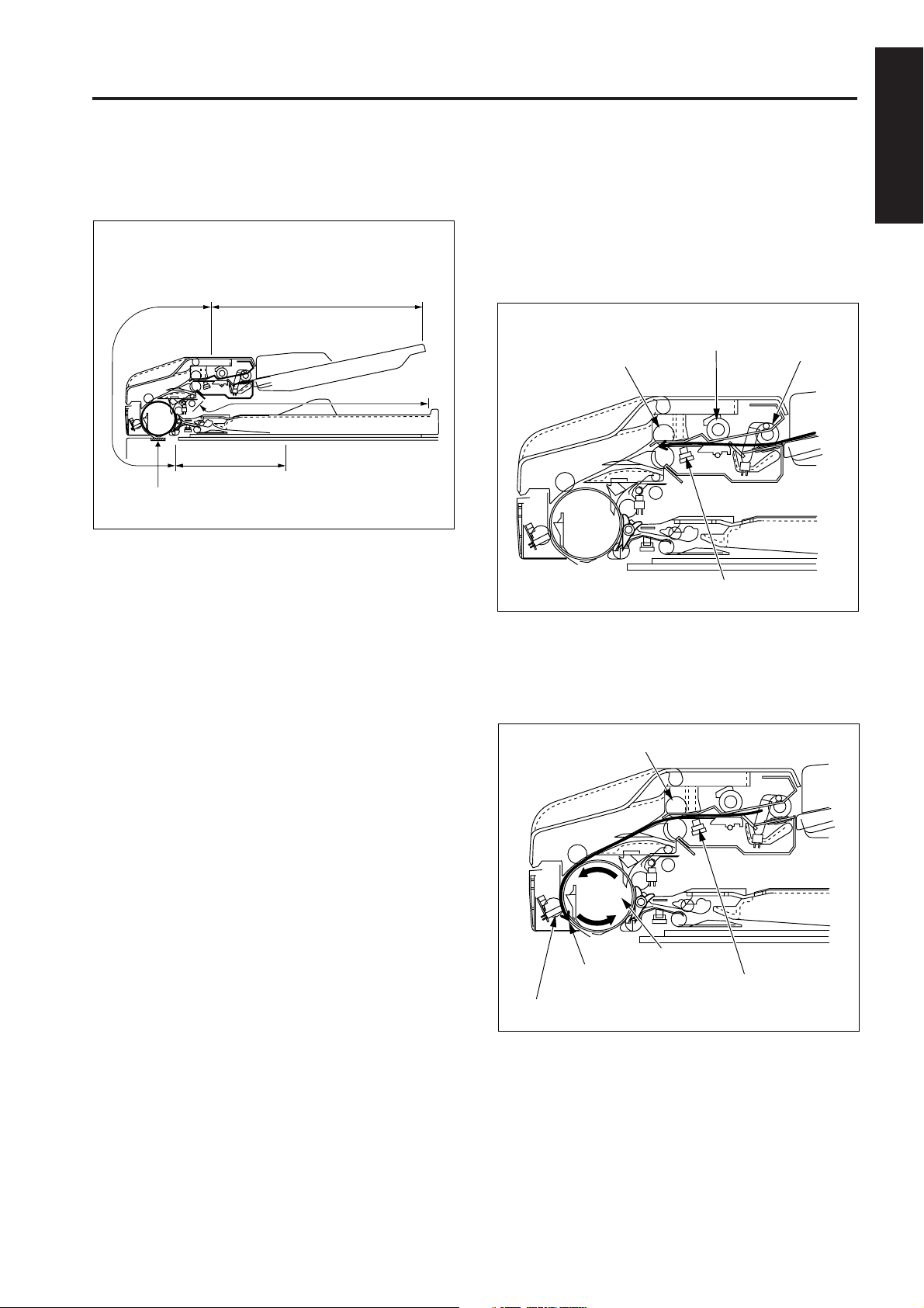
ORIGINAL CONVEYANCE PROCESS
DF-315
As the figure below shows, the DF-315 is composed of the
paper feed section, conveyance section, reversal section
and paper exit section.
Conveyance
section
Reversal section
Slit glass
(Read section)
The originals, which have been placed in the paper feed
tray with the front side facing up, are fed starting with the
topmost original. Originals that are fed are not conveyed
to the original glass. Reading is carried out as the original
passes by the slit glass section set midway through the
conveyance path.
The operational modes of the DF-315 include three
modes: (a) single side original copy mode, (b) double side
original copy mode, (c) mixed original copy mode. The
conveyance path is different for each mode.
Paper feed section
Paper exit section
[1] Single Side Original Copy Mode
(single side to single side copy, single side to
double side copy)
The originals set in the paper feed tray are fed by means of
the paper feed roller and separation roller to the position
where original registration PS (PS306) goes on.
Separation roller
Registration roller
Original registration PS
When original registration PS goes on, pre-feed is carried out
by the registration roller and the original is conveyed to the
conveyance roller. The conveyance roller conveys the
original to the position where original feed detect PS (PS308)
goes on. The original stops at the scanning standby position.
Registration roller
Paper feed roller
1 OUTLINE
2 UNIT EXPLANATION
3 DIS./ASSEMBLY
1-3
Conveyancec roller
Scanning standby
position
Original feed detect PS
Original registration PS
Page 10
1 OUTLINE
2
2 UNIT EXPLANATION
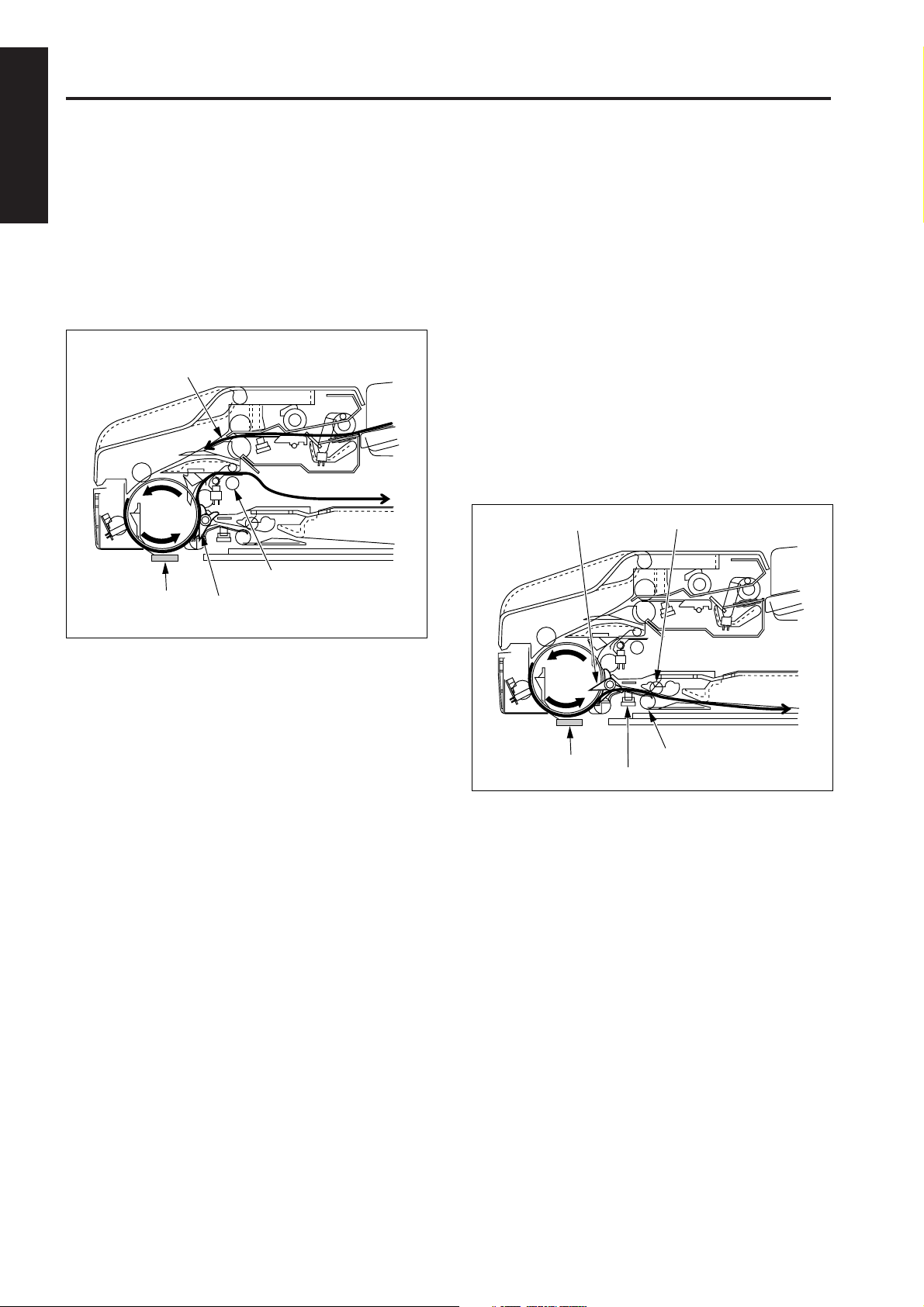
DF-315
When scan is started, the conveyance roller rotates again
in the forward direction to convey the original. If there is
another original at this time, pre-feed is carried out.
Reading of the original is carried out when the original
passes over the slit glass. Originals which have been read
are conveyed around the circumference of the
conveyance roller by closing of the flapper and are ejected
to the paper exit section via the paper exit roller.
Next original
[2] Double Side Original Copy Mode
(double side to single side copy, double side to
double side copy)
The conveyance operation from feeding of the double
sided original to the front side scanning standby position is
the same as that for the single side original copy mode.
When scanning starts and reading of the front side is
completed, the original is conveyed to the reversal section
when the flapper opens and the paper exit path is blocked.
When original reverse detect PS (PS309) detects the
leading edge of the original that has been conveyed to the
reversal section and goes ON, pressure is applied to the
pressure pulley. As a result, the reversal roller and
pressure pulley clasp the original on both sides and
convey it to the inside of the reversal section.
Flapper
Paper exit roller
3 DIS./ASSEMBLY
Slit glass
Flapper
Slit glass
Pressure pulley
Reversal roller
Original reverse detect PS
1-4
Page 11
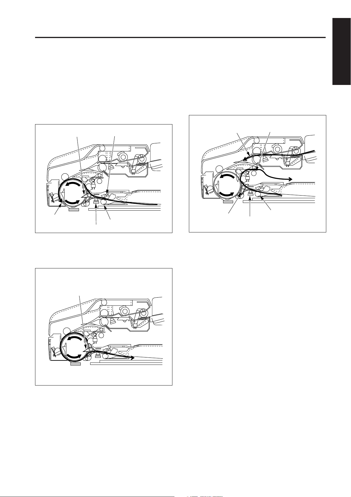
DF-315
When original reverse detect PS (PS309) detects the trailing
edge of the original and goes OFF, the reversal roller rotates in
the reverse direction to feed the original from the reversal
section to the conveyance roller. Since the original passes
over the top of the flapper at this time, the front and back sides
are reversed and the original is sent to the conveyance roller.
The conveyance roller conveys the original to the
scanning standby position.
Flapper Pressure pulley
Scanning
standby position
Original reverse detect PS
Reversal roller
When original reverse detect PS detects the trailing edge of
the original and goes OFF, the reversal roller rotates in the
reverse direction to feed the original from the reversal
section to the conveyance roller. Since the flapper is
closed at this time, the original is conveyed along the
flapper and is ejected to the paper exit section via the
paper exit roller.
Next original
Flapper
Original reverse detect PS
Paper exit roller
Reversal roller
1 OUTLINE
2 UNIT EXPLANATION
3 DIS./ASSEMBLY
When scanning of the back side starts, the flapper is
opened. As a result, the original which has been read is
conveyed to the inside of the reversal section again.
Flapper
[3] Mixed Original/Z-Fold Original Mode
In the mixed original mode (can handle both same
series and different series of originals) and the Z-fold
original mode, the original size in the sub-scanning
direction is determined by to the ON time of original
registration PS (PS306), hence size detection takes
place before the scanning operation. This operation
takes place for all originals in the mixed original
mode, and only for the first original in the Z-fold
original mode.
After size detection is completed, the original stops at
the scanning standby position. The subsequent
operations are the same for all copy modes. For
details of the size detection process, refer to [5]
"Original Size Detection Control" in "PAPER FEED/
PAPER EXIT SECTION".
1-5
Page 12

1 OUTLINE
2
2 UNIT EXPLANATION
DF-315
3 DIS./ASSEMBLY
Blank page
1-6
Page 13

2
UNIT EXPLANATION
1 OUT LINE
2 UNIT EXPLANATION
3 DIS./ASSEMBLY
Page 14

1 OUT LINE
2
2 UNIT EXPLANATION
3 DIS./ASSEMBLY
Blank page
Page 15

EXTERNAL SECTION
DF-315
[1] Composition
1 OUT LINE
Open/close cover
Paper feed tray
2 UNIT EXPLANATION
Paper exit section
3 DIS./ASSEMBLY
[2] Mechanisms
Mechanisms
Jam clearance
1*: Jam clearance
If a paper jam occurs during the feed process, open
the open/close cover, raise the conveyance guide
open/close lever, and rotate the release knob to
remove the jammed original.
Open/close cover *1
Release knob
Conveyance guide open/close
lever
Pressure release lever
Platen guide
Methods
Open/close cover
Release knob
Conveyance
guide open/close
lever
Conveyance guide
2-1
Page 16

1 OUT LINE
2
2 UNIT EXPLANATION
DF-315
If the jammed original is hard to remove, operate the
pressure release lever to remove the pressure of the
separation roller, and then remove the original.
Separation roller
Pressure release lever
If a paper jam occurs during the reversal process, the
jammed sheet can be removed by opening the platen guide.
3 DIS./ASSEMBLY
Platen
guide
Lock
2-2
Page 17

PAPER FEED/PAPER EXIT SECTION
DF-315
[1] Composition
[2] Mechanism
Open/close cover
Original press SD
Flapper SD
Paper feed tray
Paper exit tray
Paper feed roller
Original feed motor
Original feed CL
1 OUT LINE
Registration roller
Separation roller
2 UNIT EXPLANATION
Conveyance roller
Original conveyance motor
Original pick-up CL
3 DIS./ASSEMBLY
Mechanisms
Paper feed
Double feed prevention
Conveyance
Conveyance path switching
Reversal feed *2
*1
Methods
Paper feed roller
Double feed prevention pad
Separation roller
Conveyance roller
Flapper
Reversal roller pressure
Reversal roller turn-back
2-3
Page 18

DF-315
1 OUT LINE
2
2 UNIT EXPLANATION
3 DIS./ASSEMBLY
*1: Conveyance path switching
In the double side original copying, the conveyance
path after the end of reading operations differs for
front side copies and back side copies. Change of
the conveyance path is carried out by the flapper.
Turning flapper SD (SD301) ON and OFF switches
between the reversal section and the paper exit
section.
Conveyance roller
Flapper
Flapper SD
*2: Reversal feed
During double side original copy operation, the
original conveyed to the reversal section is held in the
standby mode on the reversal roller. Reversal feed is
activated by bringing the pressure pulleys into
contact with the reversal roller. Pressure of the
pressure pulleys is conducted by original press SD
(SD302).
Pressure pulley
Reversal roller
Pressure pulleys
Flapper
Original press SD
2-4
Page 19

DF-315
[3] Paper Feed/Conveyance/Scan Control
PS302
PS303
5VDC
SGND
PS302
5VDC
SGND
PS303
PTBD
24VDC
PGND
PGND
SGND
DF RXD
DSR
RTS
5VDC
PGND
24VDC
24VDC
MAIN BODY
5VDC
PS303
PS302
SGND
VR301
DF TXD
CTS
DTR
VALID
DFCB
24VDC
24VDC
M301 DRIVE A
M301 DRIVE A
M301 DRIVE B
M301 DRIVE B
M302 DRIVE 1
M302 DRIVE 2
24VDC
CL301 DRIVE
24VDC
CL302 DRIVE
24VDC
SD301 DRIVE
24VDC
SD302 DRIVE
5VDC
PS304
SGND
5VDC
SGND
PS306
5VDC
PS309
SGND
PS305
SGND
5VDC
M301
M302
CL301
CL302
SD301
SD302
PS304
PS307
PS309
PS305
1 OUT LINE
2 UNIT EXPLANATION
3 DIS./ASSEMBLY
Paper feed takes place by transmitting the drive force of
motor M302 (original feed) to the paper feed roller and
separation roller. Conveyance takes place by transmitting
the drive force of motor M301 (original conveyance) to the
conveyance roller.
M301 and M302 are controlled by the DFCB (RADF control
board).
1. Operation
a. Sensor adjustment when the power is ON.
When SW2 (sub power) is ON, a sensitivity PS306
(original registration) and PS308 (original feed detect)
is adjusted automatically. However, if the RADF open/
close cover is open or an original is inside of the
RADF, there will be no automatic adjustment.
b. Original pressure operation
When a control signal from the main body is received,
CL301 (original pick-up) goes ON, and after the
specified time M302 starts to rotate in the forward
direction. This causes the paper feed roller to be
lowered, applying pressure to the original.
After the specified time, M302 and CL301 go OFF,
but the pressure on the original is maintained.
2-5
Page 20

DF-315
1 OUT LINE
2
2 UNIT EXPLANATION
3 DIS./ASSEMBLY
c. Paper feed operation
When CL302 (original feed) goes ON, the driving
force of M302 (original feed) is transmitted to the
paper feed roller and the separation roller.
CL302 goes ON at the same time as M302 performs
forward rotation. When M302 switches from forward
to reverse rotation, paper feed starts.
When PS306 (original registration) goes ON, the
reverse rotation of M302 is switched OFF after the
specified time.
d. Pre-feed of first sheet
When the reverse rotation of M302 stops, the motor
starts again to rotate in forward direction after the
specified time.
This causes the original to be moved to the
conveyance roller.
At the specified time after forward rotation of M302
has started, M301 (original conveyance) goes ON
and moves the original from the conveyance roller
to the scanning standby position.
When PS308 (original feed detect) detects the
leading edge of the original and turns ON, CL302 and
M302 go OFF. After the specified time, M301 slows
down and then goes OFF. At this point, the original
still moves a small distance further due to the inertia
of the conveyance roller and then stops. This is the
scanning standby position.
h. Original pressure release
When M301 completes the scanning operation for
the last original and goes OFF, CL301 and M302 go
ON which causes the original pressure to be
released. After the specified time, CL301 and M302
go OFF.
e. Pre-feed of second and further sheets
The forward rotation of M302 starts the pre-feed
process of the following original, but because the
motor immediately goes OFF, the original temporarily
stops before reaching the conveyance roller. When
M301 begins the scanning operation, the forward
rotation of M302 starts again. Pre-feed of the original
then is carried out while the preceding original is
being scanned.
f. Scanning operation (except last original)
At the specified time after M301 goes OFF, it goes
ON again and conveys the original over the slit glass
area of the main body, where scanning is performed.
When PS306 detects the trailing edge of the original that
is being scanned and goes OFF, CL302 again goes ON
g. Scanning operation (last original)
During scanning, when M301 is ON and one of the
sensors PS302 (original size detect 1), PS303
(original size detect 2), or PS305 (no original detect)
goes OFF, the original currently being scanned is the
last one.
A sensor that is used to judge the last original differs
depending on the original size.
When PS307 (original exit detect) goes OFF, M301
also is switched OFF after the specified time.
2-6
Page 21

DF-315
24V
0V
2. Signals
a. Input signals
(1) PS302 (PS302 to PTDB to DFCB)
Original sub-scanning direction signal
[L]: Original is detected
[H]: Original is not detected
(2) PS303 (PS303 to PTDB to DFCB)
Original sub-scanning direction signal
[L]: Original is detected
[H]: Original is not detected
(3) PS304 (PS304 to DFCB)
M301 (original conveyance) encoder surface slit
detection signal
[L]: Slit is not detected
[H]: Slit is detected
(4) PS305 (PS305 to DFCB)
No original detection signal at the paper feed tray
[L]: Original is detected
[H]: Original is not detected
(5) PS306 (PS306 to DFCB)
Original detection signal at the conveyance roller en
trance section
[L]: Original is detected
[H]: Original is not detected
(6) PS307 (PS307 to DFCB)
Original detection signal at the paper exit section
[L]: Original is detected
[H]: Original is not detected
(7) PS308 A, B (PS308 to DFCB)
Original detection signal at the pre-scanning standby
position
[L]: Original is detected
[H]: Original is not detected
(8) DF RXD (MAIN BODY to DFCB)
Serial data line for transmitting operation status
informa tion from control board in main body to
RADF.
b. Output signals
(1) M301 DRIVE A, A, B, B (DFCB to M301)
M301 ON/OFF drive signal
(2) M302 DRIVE 1, 2 (DFCB to M302)
M302 (original conveyance) drive signal.
M302 rotation direction is controlled by switching the
current direction of these two signals.
State
Forward rotation
Reverse rotation
Stop
(3) CL301 DRIVE (DFCB to CL301)
CL301 (original pick-up) ON/OFF drive signal
[L]: CL301 ON
[H]: CL301 OFF
(4) CL302 DRIVE (DFCB to CL302)
CL302 (original feed) ON/OFF drive signal
[L]: CL302 ON
[H]: CL302 OFF
(5) DF TXD (DFCB to MAIN BODY)
Serial data line for transmitting operation status
informa- tion from RADF to main body CB (control
board).
(6) DTR (DFCB to MAIN BODY)
Send request from RADF to main body.
(7) CTS (DFCB to MAIN BODY)
Send enable from RADF to main body.
(8) VALID (DFCB to MAIN BODY)
Image forming start signal.
M302 DRIVE 1
H
L
L
M302 DRIVE 2
1 OUT LINE
L
H
L
2 UNIT EXPLANATION
3 DIS./ASSEMBLY
(9) DSR (MAIN BODY to DFCB)
Send enable from main body to RADF.
(10) RTS (MAIN BODY to DFCB)
Send request from main body to RADF.
2-7
Page 22

DF-315
1 OUT LINE
2
2 UNIT EXPLANATION
3 DIS./ASSEMBLY
[4] Paper Exit/Reverse Conveyance
Control
24VDC
24VDC
M301 DRIVE A
M301 DRIVE A
M301 DRIVE B
M301 DRIVE B
M302 DRIVE 1
M302 DRIVE 2
5VDC
PS304
SGND
SGND
PS306
5VDC
5VDC
SGND
PS307
5VDC
PS308 A
PS308 B
SGND
24VDC
PGND
PGND
SGND
DF RXD
5VDC
PGND
24VDC
24VDC
MAIN BODY
DSR
RTS
DF TXD
CTS
DTR
VALID
DFCB
Paper path switching in the exit area is carried out by
solenoid SD301 (flapper) which operates a flapper. In
duplex copy mode, the pressure pulley in the reversal
section is operated by the SD302 (original press).
SD301 and SD302 are controlled by the DFCB (RADF
control board).
M301
M302
PS304
PS306
PS307
PS308
1. Operation
a. Sensor adjustment when the power is ON.
When SW2 (sub power) is ON, a sensitivity of PS309
(original reverse detect) is adjusted automatically.
However, if the RADF open/close cover is open or an
original is in the inside of the RADF, there will be no
automatic adjustment.
b. Paper exit operation
In single-sided copy mode and when copying the
reverse side of a sheet in duplex copy mode, SD301
is OFF and the flapper is closed. The original is
therefore conveyed to the paper exit section after
scanning.
c. Reversal paper exit operation
When copying the first side of a sheet in duplex copy
mode, at the specified time after M301 (original
conveyance) goes ON and scanning starts, SD301
goes ON and the flapper opens. This causes the
original to be sent to the reversal section after
scanning.
At the same time as SD301 goes ON, M302 (original
feed) starts reverse rotation and the drive force is
transmitted to the reversal roller.
When PS309 detects the leading edge of the original
and goes ON, the SD302 goes ON after the specified
time and applies pressure to the pressure pulley. As
a result, the original which has been conveyed to the
reversal section is caught between the reversal roller
and pressure pulley, and conveyed to the inside of
the reversal section.
d. Reversal feed operation
When PS309 detects the trailing edge of the original
and goes OFF, both the M301 and M302 go OFF
after the specified time, and conveyance operation of
the original is stopped.
After a predetermined OFF interval, M302 starts
reverse rotation and feeds the original to the
conveyance roller side of the reversal section. At this
time, PS309 again goes ON and SD302 goes OFF
after the specified time. M302 goes OFF after the
specified time from PS309 goes OFF.
e. Pre-feed operation of next original when reading
back side of original
When PS309 goes OFF, M301 and M302 start
forward rotation after the specified time, and next
original pre-feed is carried out.
2-8
Page 23

DF-315
2. Signals
a. Input signal
(1) PS309 (PS309 to DFCB)
Original detection signal at the reversal section
[L]: Original is detected
[H]: Original is not detected
b. Output signals
(1) SD301 DRIVE (DFCB to CL301)
SD301 (flapper) ON/OFF drive signal
[L]: SD301 ON
[H]: SD301 OFF
(2) SD302 DRIVE (DFCB to SD302)
SD302 (original pressure) drive signal
[L]: SD301 ON
[H]: SD302 OFF
1 OUT LINE
2 UNIT EXPLANATION
3 DIS./ASSEMBLY
2-9
Page 24

DF-315
1 OUT LINE
2
2 UNIT EXPLANATION
3 DIS./ASSEMBLY
[5] Original Size Detection Control
5VDC
SGND
PS302
5VDC
SGND
PS303
5VDC
VR301
SGND
PTDB
PS303
PS302
VR-301
24VDC
PGND
PGND
SGND
DF RXD
5VDC
PGND
24VDC
24VDC
MAIN BODY
DSR
RTS
5VDC
DF TXD
CTS
DTR
DFCB
SGND
PS302
PS303
VR301
1. Operation
a. Normal copy mode
The DFCB detects the original size from the
combination of the following signals.
(1) Detection of size in the main scanning direction
The guide plate is connected to VR301. The
resistance of VR301 varies according to the position
of the guide plate, enabling the size of the original in
the main scanning direction to be detected.
(2) Detection of size in the sub-scanning direction
The size of the original in the sub-scanning direction
is detected according to the combination of the ON/
OFF status of PS302 and PS303.
b. Original size detection in the mixed original/Z-
fold original mode
(1) Detection of size in the main scanning direction
The size of the largest original of mixed size originals
in the main scanning direction is detected according
to the position of the guide plate.
(2) Detection of size in the sub-scanning direction
The size of the original in the sub-scanning direction
is detected according to the time at which PS306
(original registration) goes ON after the original is fed
from the registration roller.
(3) Size detection process in the sub-scanning direction
When original pre-feed is started by the registration
roller, M301 (original conveyance) rotates in the
forward direction after the specified time from when
PS306 goes ON, causing the original to be conveyed
to the paper exit section. M301 continues to rotate in
the forward direction until PS306 detects the trailing
edge of the original and goes OFF. The size of the
original in the sub-scanning direction is detected
according to the ON time of PS306.
The size of the original placed in the paper feed tray is
detected by PS302 (original size detect 1), PS303 (original
size detect 2), and VR301 (original size detect).
PS302, PS303, and VR301 are controlled by the DFCB
(RADF control board) via the PTBD (Paper tray board).
Inside the DFCB is a non-volatile memory for recording
the timing data and original size detection threshold
values.
2-10
Registration roller
PS308
(Original feed detect)
PS306
(Original registration)
Conveyance roller
Page 25

DF-315
Standard original (maximum original size that is detected with the guide plate).
Other originals
11×17
8.5×11
8.5
×
14
8.5
×
11R
8.5
×
5.5
8.5×5.5R
11×17 8.5×11 8.5×14 8.5×11R 8.5×5.5 8.5×5.5R
–
–
–
–
–
–
–
–
–
–
–
✕✕✕✕ ✕
M301 (original conveyance) rotates in the reversal
direction after the specified time from PS306 (original
registration) goes OFF and returns the leading edge
of the original that has been conveyed to the paper
exit section to the scanning standby position. The
trailing edge of the original which has been returned
is conveyed to the exit section due to the
configuration of the conveyance section. The
reversal rotation of the M301 stops after the specified
time from PS308 (original feed detect) detects the
leading edge of the original and goes ON.
Scanning standby
position
PS308
(Original feed detect)
Conveyance roller
Following this, there is the same reading as in the
normal mode (scanning operation).
The process of detecting the size of the original in the
sub-scanning direction takes place only for in the all
originals in the mixed original mode, and for the first
original in the Z-fold original mode.
(4) The original size detection operation with the second
original and subsequent originals has a different start
timing for the single side mode and double side mode.
Single side mode: At time of starting scanning opera-
tion of former original.
Double side mode: At time of starting scanning opera-
tion of former original back side.
2nd original
1st original
c. List of the possible mixing of sizes.
(
: Same size : Same series : Different series
× : Mixing not possible – : Setting not possible.)
(1) AB series
Standard original (maximum original size that is detected with the guide plate).
A3 A4 B4 B5 A4R A5R B5R A5
A3
A4
B4
B5
A4R
A5
Other originals
B5R
A5R
✕✕✕
–––––
✕✕✕✕
✕
–
–
–
–
–
–
–
–
–
–
–
–
–
–
–
–
–
–
–
–
1 OUT LINE
2 UNIT EXPLANATION
3 DIS./ASSEMBLY
(2) Inch series
2. Signals
a. Input signal
(1) VR301 (VR301 to PTBD to DFCB)
Original main scanning direction signal
2-11
Page 26

1 OUT LINE
2
2 UNIT EXPLANATION
DF-315
3 DIS./ASSEMBLY
Blank page
2-12
Page 27

3
DISASSEMBLY/ASSEMBLY
1 OUT LINE
2 UNIT EXPLANATION
3 DIS./ASSEMBLY
Page 28

1 OUT LINE
2
2 UNIT EXPLANATION
3 DIS./ASSEMBLY
This section covers the structure, functions, operation and method of
disassembling and assembling the machine.
Observe the following precautions when performing disassembly and
assembly work.
1. Be sure to unplug the power cord before working on the machine.
2. Perform all reassembly work by reversing the order in which the
componet was disassembled, unless otherwise specified.
3. Do not lose small parts (screws, etc.) or insert them in the wrong
place.
4. Install all parts completely before operating the machine.
5. Do not loosen the screws indicated as disallowed for removal.
Page 29

DISASSEMBLY AND REASSEMBLY
DF-315
Caution: Be sure that the power cord has
been unplugged from the power
outlet.
[1] Removing and Reinstalling the Paper
Dust Removing Pad
a. Procedure
(1) Open the open/close cover.
(2) Remove the set screw, then remove the paper dust
removing pad.
Paper dust removing pad
Set screw
[2] Removing the RADF
a. Procedure
(1) Remove the rear cover from the main body.
(2) Remove the two connectors (CN100, CN102).
(3) Remove the set screw, then withdraw the cable from
the main body.
Cable
Set screw
Connector
(CN102)
Connector
(CN100)
1 OUT LINE
2 UNIT EXPLANATION
3 DIS./ASSEMBLY
(3) Reinstall the paper dust removing pad in the opposite
sequence to removal.
3-1
Page 30

DF-315
1 OUT LINE
2
2 UNIT EXPLANATION
3 DIS./ASSEMBLY
(4) Remove the set screw from each, then remove the two
stoppers.
(5) Remove the two set screws from each, then remove the
two fixing plates/R.
Set screw
Stopper
Fixing
plate/R
Set
screws
(6) Open the RADF.
(7) Remove the set screw from each while supporting the
RADF, then remove the two fixing plates/F.
(8) Remove the RADF from the main body.
Fixing plate/F
Set
screw
3-2
Caution: Be sure to support the RADF during
this process as it may fall to the rear
side when the fixing plate/F has been
removed.
Page 31

DF-315
[3] Reinstalling the RADF
a. Procedure
(1) Remove the two set screws, then remove the original
stopper plate of the main body.
Set screw
Original stopper plate
Set screw
(2) Install the two RADF positioning jigs in the hole of the
original stopper plate.
(3) After installing the RADF, temporarily fix the two fixing
plates /F using one set screw each.
Caution: Set each fixing plate/F with the long
hole over the guide screw.
(4) Close the RADF, and match the reference hole with the
RADF positioning jig.
Guide screw
Set screw
Reference
hole
(round hole)
Reference
hole
(long hole)
Fixing plate/F
1 OUT LINE
2 UNIT EXPLANATION
3 DIS./ASSEMBLY
RADF
positioning jigs
3-3
Page 32

DF-315
1 OUT LINE
2
2 UNIT EXPLANATION
3 DIS./ASSEMBLY
(5) When the positions are matched, tighten the two set
screws of each fixing plate /R.
(6) Open the RADF, then tighten the set screw of each
fixing plate /F.
Set screws
Fixing plate/R
(9) Adjust the adjustment screws A and B alternately so
that both stoppers contact with the slit glass.
Caution: Repeat Step (8) to (9) until both stoppers
make contact with the slit glass
simultaneously.
Adjustment
screw B
(10) Reinstalling hereafter is performed in the opposite
sequence to removal.
Adjustment
screw A
(7) Remove the two RADF positioning jigs, then install the
original stopper plate.
(8) Close the RADF, and check whether or not the stoppers
of the read section at the two locations contact with the
slit glass.
Stopper
Projection
Projection
Slit glass
Stopper
3-4
Page 33

DF-315
[4] Removing and Reinstalling the Paper
Feed Roller/Separation Roller
a. Procedure
(1) Remove the four set screws to remove the rear cover.
Set screws
Set screws
Rear cover
(2) Open the open/close cover.
(3) Rotate the gear until the two pressure pins on the pick-
up shaft point up.
Gear
(4) Remove the two springs.
(5) Remove the stop ring and slide the bearing to the side.
(6) Slide the paper feed roller assembly towards the front
side, then remove it.
Bearing
Front
Stop ring
Springs
Paper feed
roller assembly
(7) Remove the bearing.
(8) Remove the two stop rings, then remove the guide
lever.
Separation roller
Pick-up clutch
Stop rings
Bearing
1 OUT LINE
2 UNIT EXPLANATION
3 DIS./ASSEMBLY
Pressure
pin
Pick-up shaft
Caution: The pick-up shaft cannot be turned
directly. Be sure to rotate it via the gear.
Paper
feed
drive
belt
Paper feed roller
Spring
Guide lever
Side shape of roller
(9) Remove the separation roller and paper feed roller.
Caution: When reinstalling the separation roller,
pay attention to correct roller orientation.
(The correct orientation can be determined
by looking at the side shape of the roller.)
(10) Reinstall the paper feed roller and separation roller in
the opposite sequence to removal.
3-5
Page 34

DF-315
1 OUT LINE
[5] Removing and Reinstalling the
Double Feed Prevention Pad
2
a. Procedure
(1) Remove the paper feed roller assembly.
(2) Push the pressure release lever so that on the double
feed prevention pad is released.
Double feed
prevention pad
Pressure
release lever
2 UNIT EXPLANATION
3 DIS./ASSEMBLY
(3) Push the double feed prevention pad down, slide it
towards the paper feed tray, and then remove it.
Double feed prevention pad
(4) Reinstall the double feed prevention pad in the opposite
sequence to removal.
Paper feed tray
3-6
 Loading...