

Page 1

1
OUTLINE
1 OUTLINE
2 UNIT EXPLANATION
3 DIS./ASSEMBLY
Page 2

1 OUTLINE
2
2 UNIT EXPLANATION
3 DIS./ASSEMBLY
Blank page
Page 3
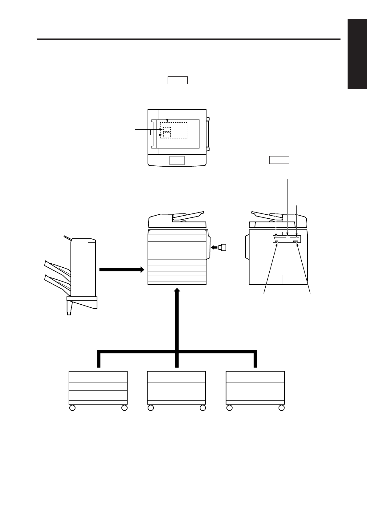
OUTLINE OF SYSTEM
CB(Control board)
Expansion memory unit
[MU-403/404/405]
OUTLINE OF SYSTEM
1 OUTLINE
Top
Finisher [FS-109]
Main body [7045]
Key counter
Back
Printer controller [IP-431]
Hard disk
[HD-103]
PostScript
[PS-342]
Network board
[KN-303]
Expansion memory
unit for printer
[MU-403/404]
2 UNIT EXPLANATION
3 DIS./ASSEMBLY
PFU 3 trays
[DB-208]
PFU 1 tray
[DB-208A]
1-A-1
PFU 1 tray + LCT
[DB-608]
Page 4

7045 PRODUCT SPECIFICATIONS
7045 PRODUCT SPECIFICATIONS
1 OUTLINE
2
2 UNIT EXPLANATION
3 DIS./ASSEMBLY
1. Type
Type: Semi-console type
Copying method: Indirect electrostatic method
Original table method:
Fixed
Photosensitive material:
OPC
Sensitizing method: Laser writing
Paper feed trays: One stacked tray
(500 sheets; 80g/m
Multisheet by-pass tray
(100 sheets; 80g/m2)
PFU (500 sheets/tray, 80g/
2
m
x 1 tray, or 3 trays)*1
LCT (1500 sheets; 80g/m
*1: Option
2. Functions
Originals: Sheets; book; solid object
Original size: A3 max.
Copy sizes: A3 to A5, F4, 8.5 x 14,
8.5 x 11
ADU usable paper size:
A3 to A5R, 8.5 x 14,
8.5 x 11, 8.5 x 11R,
Magnification:
Fixed magnifications:
x1.00, x1.15, x1.22, x1.41,
x0.86, x0.82, x0.71
Special ratio: Three kinds.
Zoom magnifications:
x0.25 to x4.00 (1% steps)
Vertical magnifications:
x0.25 to x4.00 (1% steps)
Horizontal magnifications:
x0.25 to x4.00 (1% steps)
Warm-up time: Within 90 seconds (at 20˚C,
at rated voltage)*1
*1 Warm-up time differs de-
pending on the Power
Source (Voltage).
First copy out time: Approx. 3.9 seconds
* When using face-up paper
exit, manual mode, platen
mode and tray 1 are in
use.
Continuous copy speed (life size copies/min):
Size CPM
A4 / 8.5x11 45
Continuous copy count:
1 to 999
Copy density selections:
manual (9 steps), AE
Arbitrary density (2 modes)
Resolution: 600 dpi x 600 dpi
2
)
2
)*1
E-RDH memory: Standard 32 MB
Maximum 288 MB
Application functions:
Sheet/Cover Insertion, Chapter, Combination (2-in-1, 4-in-1,
8-in-1), Booklet, Special paper,
Image Insert, Dual page, Special Original, Text/Photo Enhance (text/photo/Increase),
Reverse Image, Repeat,
Frame/Fold Erasure, Auto Layout, Image Shift, Non-image
Area Erase, memory function,
density monitor, single step
copy, density shift, printing
function, copy reservation, original rotation, weekly timer, job
memory, KRDS
3. Applicable copy paper
Plain paper: 60 to 90 g/m2 high-quality paper
Special paper: Label paper
(by-pass feed only) OHP film
Blueprint-master paper
50 to 59 g/m2 high-quality paper
91 to 130 g/m
2
high-quality paper
1-A-2
Page 5

7045 PRODUCT SPECIFICATIONS
4. Options
Finisher: FS-109
Drawer base unit: DB-208 (500 x 3 trays)
DB-208A (500 x 1 tray)
DB-608 (500 X 1 tray + 1500 LCT)
Key counter
Expansion memory unit
Printer controller: IP-431
Hard disk: HD-103
Network board: KN-303
PostScript: PS-342
: MU-403 (32MB DIMM)
MU-404 (64MB DIMM)
MU-405 (128MB DIMM)
5. Particulars of machine
Power supply: 230 VAC -14.0% to 10.6% (for Europe)
120 VAC ±10.0% (for U.S.A.)
Power consumption: Max. 1800W (for Europe)
(Full option) Max. 1500W (for U.S.A.)
Weight: Approx. 104 kg
Machine dimensions: Width: 647mm
Depth: 706mm
Height: 745mm
1 OUTLINE
2 UNIT EXPLANATION
3 DIS./ASSEMBLY
6. Maintenance and Life
Maintenance: Every 100,000 copies
Machine life: 1,200,000 copies or 5 years
7. Consumables
Developer: Common with Konica 7033/7040
Toner: Common with Konica 7040
Drum: Common with Konica 7033/7040 (φ60)
8. Environmental conditions
Temperature: 10˚C to 30˚C
Humidity: 10% to 80%RH
Note: Specifications are subject to change without notice.
1-A-3
Page 6

1 OUTLINE
2
2 UNIT EXPLANATION
CENTER CROSS-SECTIONAL VIEW
CENTER CROSS-SECTIONAL VIEW
DF-315 (standard)
CB (control board)
Exposure lamp
Charging corona section
Slit glass
PCL
Image write section
Cleaning unit
Fixing unit
Original
image read
position
Image read section
ICB (image control
board)
Developing section
2nd paper feed section
3 DIS./ASSEMBLY
Reversal/Paper
exit unit
ADU section
Tray 1
Conveyance
section
Separation corona
section
TSL
By-pass tray
Transfer corona section
Paper feed section
1-A-4
Page 7

DRIVE SYSTEM DIAGRAM
DRIVE SYSTEM DIAGRAM
[1] Main Drive
Main motor (M1)
1 OUTLINE
Registration MC (MC1)
Registration roller (upper)
2 UNIT EXPLANATION
Registration roller
(lower)
3 DIS./ASSEMBLY
Conveyance belt
Fixing roller (upper)
Fixing roller (lower)
1-B-1
Page 8

1 OUTLINE
2
2 UNIT EXPLANATION
DRIVE SYSTEM DIAGRAM
[2] Drum / Toner Recycle Drive
Drum
Drum motor (M4)
3 DIS./ASSEMBLY
Separation claw swing gear
Toner conveyance screw
Toner recycle screw
1-B-2
Page 9

DRIVE SYSTEM DIAGRAM
[3] Developing Drive
Developing motor (M3)
Developing MC
(MC2)
1 OUTLINE
2 UNIT EXPLANATION
Developing drive input gear (1)
Agitator screw
3 DIS./ASSEMBLY
Developing drive
input gear (2)
Developing sleeve
Agitator wheel
1-B-3
Page 10

1 OUTLINE
2
DRIVE SYSTEM DIAGRAM
[4] By-pass Paper Feed / 1st Paper Feed Drive
By-pass paper feed roller
A
2 UNIT EXPLANATION
3 DIS./ASSEMBLY
By-pass SD (SD4)
Tray motor (M8)
1st paper feed motor (M6)
By-pass double feed
prevention roller
By-pass separation roller
A
Paper feed pulley
Paper feed pulley
Registration paper feed
roller
Paper feed roller
Paper conveyance pulleys
Separation roller
Double feed prevention roller
1-B-4
Page 11

DRIVE SYSTEM DIAGRAM
[5] ADU Drive
Conveyance roller (B)
Conveyance roller (C)
Registration roller (upper)
Registration
roller (lower)
1 OUTLINE
2 UNIT EXPLANATION
3 DIS./ASSEMBLY
Conveyance roller (A)
ADU paper feed
motor (M501)
ADU restart
MC (MC501)
ADU loop MC (MC502)
ADU feed MC (MC503)
1-B-5
Page 12

1 OUTLINE
2
DRIVE SYSTEM DIAGRAM
[6] Reversal / Paper Exit Drive
Reversal/paper exit motor (M12)
2 UNIT EXPLANATION
3 DIS./ASSEMBLY
Gate SD (SD5)
Paper exit reversal rollers
Reversal rollers
Paper exit rollers
Switching guide
Conveyance rollers
1-B-6
Page 13

DRIVE SYSTEM DIAGRAM
[7] Read Unit Drive
Optics wire (rear)
1 OUTLINE
Scanner motor (M2)
2 UNIT EXPLANATION
Exposure unit
3 DIS./ASSEMBLY
V-mirror unit
Optics wire (front)
1-B-7
Page 14

1 OUTLINE
2
DRIVE SYSTEM DIAGRAM
[8] Toner Supply Drive
2 UNIT EXPLANATION
3 DIS./ASSEMBLY
Toner supply motor 1 (M10)
Toner supply motor 2 (M11)
Toner cartridge drive
coupling
Agitator plate
Toner conveyance screw
1-B-8
 Loading...