

Page 1

1
OUTLINE
1 OUTLINE
2 UNIT EXPLANATION
3 DIS./ASSEMBLY
Page 2

1 OUTLINE
2
2 UNIT EXPLANATION
3 DIS./ASSEMBLY
Blank page
Page 3
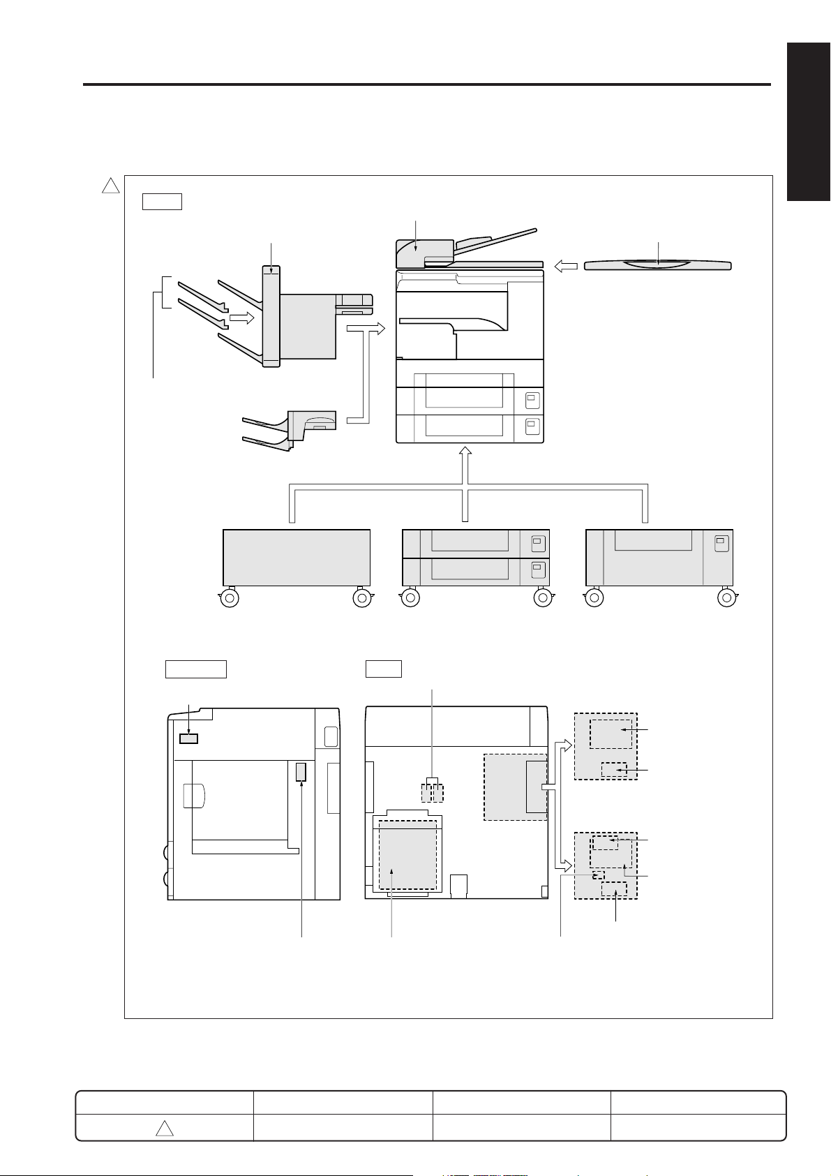
OUTLINE OF SYSTEM
OUTLINE OF SYSTEM
The copier supports the options shown below.
2
Front
Finisher [FS-107]
Finisher Trays [FT-107]
Inner Tray Unit [IT-101]
1 OUTLINE
RADF [DF-314]
Platen Cover [CV-109]
Main body
2 UNIT EXPLANATION
3 DIS./ASSEMBLY
Pedestal [DK-109]
Right Side Rear
Key counter
Total counter
2-Tray DB [DB-209/210]*
E-RDH/FAX expansion memory [MU-403/404/405]
Fax control board [FK-101]
Postscript option [PS-341]
1-Tray LCT DB [DB-409/410]*
Printer controller [IP-011]
Network board
[KN-304]
Expansion memory
[MU-403/404]
Printer controller [IP-421]
Expansion memory
[MU-403/404/405]
Network board [KN-303]
Hard disk [HD-103]
* The DB-209 and DB-409 are not compatible with the 7035. The DB-210 and DB-410 are compatible with all
models.
REVISED EDITION
2
DATE
Feb. 2001
1-1
PA GE
1-1
METHOD
REPLACEMENT
Page 4
7020/25/30/35 PRODUCT SPECIFICATIONS
222
2
2
7020/25/30/35 PRODUCT SPECIFICATIONS
1 OUTLINE
2
2 UNIT EXPLANATION
3 DIS./ASSEMBLY
1. Type
Type: Semi-console type
Copying method: Indirect electrostatic method
Original table method:
Fixed
Original alignment: Left rear standard
Photosensitive material:
OPC
Sensitizing method:
Laser writing
Paper feed trays: Two trays
(500 sheets per tray; 80g/m
Multisheet by-pass tray
(50 sheets; 80g/m2)
DB-209/210 (Two trays; 500
sheets/tray; 80g/m
2
DB-409/410 (One tray; 1500
sheets; 80g/m2)*
*Option
2. Functions
Originals: Sheets; book; solid object
Original size: A3 max.
Copy sizes: A3 to A5, 11x17 to 5.5x8.5
2
U.S.A. Europe and others
Tray1
Tray2
By-pass
tray
ADU usable paper size:
2
11 × 17, 8.5 × 14,
8.5 × 11, 8.5 × 11R,
5.5 × 8.5, A3, A4,
A4R, A5R, B5, B5R, F4
8.5 × 14, 8.5 × 11,
8.5 × 11R, 5.5 × 8.5,
F4, B4, A4, A4R,
B5R, A5R
11 × 17, 8.5 × 14,
8.5 × 11, 8.5 × 11R,
5.5 × 8.5, A3, A4,
A4R, A5R, B5, B5R,
F4
11 × 17, 8.5 × 14,
8.5 × 11, 8.5 × 11R,
5.5 × 8.5, A3, A4,
A4R, A5R, B5, B5R,
F4
U.S.A. Europe and others
B4, A4, A4R, B5, B5R,
A5R, F4, 8.5 × 14,
8.5 × 11, 8.5 × 11R,
5.5 × 8.5,
A3, B4, A4, A4R, B5,
B5R, A5R, 11 × 17,
8.5 × 11, 8.5 × 11R,
F4
A3, B4, A4, A4R, B5,
B5R, A5R, 11 × 17,
8.5 × 11, 8.5 × 11R,
F4
A3, B4, A4, A4R, B5,
B5R, A5R, 11 × 17,
8.5 × 11, 8.5 × 11R, F4
Magnification:
Fixed magnifications:
x1.00, x1.41, x1.22, x1.15,
x0.86, x0.82, x0.71
Special ratio: Three kinds.
Zoom magnifications:
x0.25 to x4.00 (1% steps)
Vertical magnifications:
x0.25 to x4.00 (1% steps)
Horizontal magnifications:
x0.25 to x4.00 (1% steps)
2
)
2
)*
Warm-up time (at 20˚C, at rated voltage):
Within 30 seconds (7020/25/30)
Within 45 seconds (7035)
First copy out time:
Continuous copy speed (life size copies/min):
7020 20copies/minute
7025 25copies/minute
7030 30copies/minute
7035 35copies/minute
Continuous copy count:
Copy density selections: manual (9 steps), AE
Resolution: 600 dpi x 600 dpi
E-RDH memory: Standard 32 MB
Application functions:
Approx. 5 seconds (7020/25/30)
Approx. 4.2 seconds (7035)
1 to 999
Arbitrary density (2 modes)
Maximum 288 MB
Sheet/Cover insertion ; OHP
(Sheet/Blank Sheet Insertion,
Copy Sheet Insertion,OHP) ;
Chapter ; Image Insert ; Combination (2 in 1, 4 in 1, 8 in 1) ;
Dual Page ; Output ; Special
Original ; Store Mode ; Text/
Photo Enhanced (Increace
Contrast, Text, Photo) ; Auto
Layout ; Reverse Image ; Image Shift (Image shift, Reduce
shift) ; Repeat (Vertical/Horizontal, Auto, Repeat) ; Non Image Area Erace ; Frame/Fold
Erasure (Frame Erasure, Fold
Erasure) ; Stamp (Water Mark,
Stamp, Date/Time, Page, Set
Numbering) ; Job Memory ; Application button customization ;
Weekly timer ; KRDS
REVISED EDITION
2
DATE
Feb. 2001
1-2
PA GE
1-2
METHOD
REPLACEMENT
Page 5

3. Applicable copy paper
Plain paper: 60 to 90 g/m2 high-quality
paper
Special paper: Label paper
(by-pass feed only) OHP film
Blueprint-master paper
Recycled paper
50 to 59 g/m
91 to 130 g/m
2
high-quality paper
2
high-quality paper
4. Options
RADF: DF-314
Finisher: FS-107
Drawer base unit: DB-209*/210 (2-tray)
2
DB-409*/410 (1-LCT)
* Does not support the 7035.
Inner tray unit: IT-101
2
Finisher trays: FT-107
Install up to two trays into FS-107
Pedestal: DK-109
Platen cover: CV-109
Key counter
Total counter
Expansion memory unit:
2
For E-RDH/FAX memory explanion
MU-403 : 32MB DIMM
MU-404 : 64MB DIMM
MU-405 : 128MB DIMM
Expansion memory for IP-011 printer
MU-403 : 32MB DIMM
MU-404 : 64MB DIMM
Expansion memory for IP-421 printer
MU-403 : 32MB DIMM
MU-404 : 64MB DIMM
MU-405 : 128MB DIMM
Printer controller: IP-011/421
2
Fax controller: FK-101
Network board: KN-303
2
Ethernet network option for IP-421
Network board: KN-304
Ethernet network option for IP-011
Hard disk: HD-103
2
Hard disk option for the IP-421
7020/25/30/35 PRODUCT SPECIFICATIONS
Postscript: PS-341
2
PostScript option for the IP-421
5. Particulars of machine
2
Power supply: 120 VAC ±10% (for U.S.A.)
220 to 240 VAC 10%
(for Europe)
Power consumption: Max.1170W
2
(only main body)
Weight: Approx. 72 kg
Machine dimensions:
Width: 590mm
Depth: 595mm
Height: 730mm
6. Maintenance
Periodic maintenance
Machine service life: 1,200,000 copies or 5 years
2
7. Consumables
For 7020/25/30
Developer: Exclusively for Konica 7020/25/30
Toner: Exclusively for Konica 7020/25/30
Drum: Exclusively for Konica 7020/25/30
For 7035
Developer: Exclusively for Konica 7035
Toner: Exclusively for Konica 7035
Drum (Note): Common to Konica 7020 (φ60)
Note: Common with the 7020 / 25/ 30. However,
items which do not have 7035 listed on the
package box should not be used.
: Every 100,000 copies
(φ60)
8. Environmental conditions
Temperature: 10 to 30˚C
2
Humidity: 10 to 80% RH
Note: Specifications are subject to change without
notice.
1 OUTLINE
2 UNIT EXPLANATION
3 DIS./ASSEMBLY
REVISED EDITION
2
DATE
Feb. 2001
1-3
PA GE
1-3
METHOD
REPLACEMENT
Page 6

CENTER CROSS SECTION
CENTER CROSS SECTION
1 OUTLINE
2
2 UNIT EXPLANATION
3 DIS./ASSEMBLY
1
V mirror unit
Toner bottle
Cleaning/tonerrecycling unit
Charging
corona unit
Image write unit
Exposure unit
Developing unit
Upper tray
CCD unit
Fixing unit
Drum unit
Separation
corona unit
Transfer
corona unit
ADU unit
(ADU door)
Lower tray
Tray 3/tray 4 paper
feed path
By-pass unit
Paper path when DB is
installed.
DB
Path of the paper for
making a two-sided copy
REVISED EDITION
1
DATE
May 2000
1-4
PA GE
1-4
METHOD
REPLACEMENT
Page 7

DRIVE SYSTEM DIAGRAM
DRIVE SYSTEM DIAGRAM
[1] Main drive
2
< Fixing/Cleaning/IT-101 drive>
Paper exit drive
Fixing unit
drive
IT drive coupling
Main motor (M1)
1 OUTLINE
[IT-101]
2 UNIT EXPLANATION
Cleaning/tonerrecycling unit drive
3 DIS./ASSEMBLY
<Drum Drive>
Developer agitation
drive
Main motor (M1)
Drum drive shaft
REVISED EDITION
2
DATE
Feb. 2001
1-5
PA GE
1-5
METHOD
REPLACEMENT
Page 8

1 OUTLINE
1 OUTLINE
2
2 UNIT EXPLANATION
DRIVE SYSTEM DIAGRAM
[2] Developing drive
1
Developing
sleeve
Developing unit
Drum drive
shaft
Developing
motor (M3)
3 DIS./ASSEMBLY
REVISED EDITION
1
DATE
May 2000
1-6
PA GE
1-6
METHOD
REPLACEMENT
Page 9

DRIVE SYSTEM DIAGRAM
[3] Paper feed drive
<Drive from paper feed motor to loop clutch>
1
Paper feed
motor (M9)
<Drive from loop clutch>
<a. Upper tray drive>
1 OUTLINE
Loop clutch (MC2)
2 UNIT EXPLANATION
SD1 (upper) drives
when ON.
Paper feed SD
(upper) (SD1)
3 DIS./ASSEMBLY
<b. Lower tray drive>
Loop roller
(lower)
SD2 (lower)
drives when ON.
Loop roller (upper)
Loop clutch (MC2)
Loop clutch (MC2)
Paper feed solenoid (lower) (SD2)
REVISED EDITION
1
DATE
May 2000
1-7
PA GE
1-7
METHOD
REPLACEMENT
Page 10

DRIVE SYSTEM DIAGRAM
1 OUTLINE
1 OUTLINE
1
<c. By-pass feed drive>
2
2 UNIT EXPLANATION
3 DIS./ASSEMBLY
Driven by SD3 ON.
By-pass
paper feed
SD (SD3)
<Registration clutch drive>
Registration clutch
(MC1)
Loop clutch (MC2)
Loop roller (By-pass)
Paper feed motor (M9)
REVISED EDITION
1
DATE
May 2000
1-8
PA GE
1-8
METHOD
REPLACEMENT
Page 11

DRIVE SYSTEM DIAGRAM
[4] ADU drive
1
ADU conveyance roller
(Driven by M1)
ADU conveyance rollers
(Driven by M9)
1 OUTLINE
2 UNIT EXPLANATION
3 DIS./ASSEMBLY
ADU motor (M6)
REVISED EDITION
1
ADU roller
DATE
May 2000
1-9
PA GE
1-9
METHOD
REPLACEMENT
Page 12

1 OUTLINE
1 OUTLINE
2
2 UNIT EXPLANATION
DRIVE SYSTEM DIAGRAM
[5] Reading drive
2
<Old type>
V mirror unit
Exposure unit
Optics wire (rear)
Optical motor (M2)
Optics wire (front)
3 DIS./ASSEMBLY
<New type>
2
V mirror unit
Exposure unit
Optics wire (rear)
Optical motor (M2)
REVISED EDITION
2
Optics wire (front)
Feb. 2001
DATE
1-10
PA GE
1-10
METHOD
REPLACEMENT
Page 13

DRIVE SYSTEM DIAGRAM
[6] Toner supply drive
<7020/25/30>
Toner supply motor 1 (M4)
Toner bottle SD (SD6)
Toner agitation plate
Toner conveyance screw
1 OUTLINE
2 UNIT EXPLANATION
3 DIS./ASSEMBLY
2
<7035>
Toner supply motor 2 (M10)
Toner supply motor 1 (M4)
Toner agitation plate
Toner conveyance screw
REVISED EDITION
2
DATE
Feb. 2001
1-11
PA GE
1-11
METHOD
REPLACEMENT
Page 14

1 OUTLINE
2
2 UNIT EXPLANATION
3 DIS./ASSEMBLY
Blank page
 Loading...