

Page 1

3
KRDS
3 KRDS
Page 2

3 KRDS
Blank page
Page 3

KRDS
KRDS
[1] Outline
1
If a FAX option is installed in this machine, it is not
necessary to connect a modem for KRDS. If a FAX option
is not installed, please connect a data modem for KRDS.
[2] Specifications
1. Type: Overall control board built-in type.
2. KRDS (Overall control board) Interface between
modem
: RS-232C Compatible
: Baud Rate: Max : 38.4 kbps
1
Default : 38.4 kbps
3. Basic Functions
Auto trouble notification
Operation count auto acquisition
Remote control (machine adjustment data,
rewriting of the counter limit, etc.)
Notification of frequent JAM occurrence
Replenish toner notification
Repair and other call buttons
4. FAX-KRDS*
Communications Speed : Max. 14.4 kbps (V.17)
Modulation Method : (V.17, V. 29, V.27ter,
V.27 fallback mode,
V.34)
* This specification is valid for KRDS host
application version 5.0 or higher versions.
[3] KRDS setting
This function selects whether to use KRDS.
KRDS allows the copy machine to call up the host
computer periodically and also when there is an
abnormality. Also data in the copier can be changed from
the host computer.
KRDS can execute the above functions for the following
data:
a. Data on the copier's status such as total and PM
count.
b. Data on the frequency of the partial copier such as
RADF paper feed count.
c. Data on the copier's error status such as SC (F) /JAM
1
occurrence code and count.
d. Data on the various adjustments
To use KRDS, set up as follows:
1. Initialize KRDS memory.
2. Set the type of modem and line.
(If FAX-KRDS is used, this setting is unnecessary.)
3. Enter host password.
4. Set phone number.
KRDS setting menu
1. Calling time set
2. Host password set
3. KRDS TEL No. setting
4. KRDS software SW set
3 KRDS
REVISED EDITION
1
DATE
May 2000
3-1
5. KRDS setup calling
PA GE
3-1
METHOD
REPLACEMENT
Page 4
KRDS
[4] KRDS set up
1. KRDS set up item
KRDS set up procedure
Step
Operation procedure
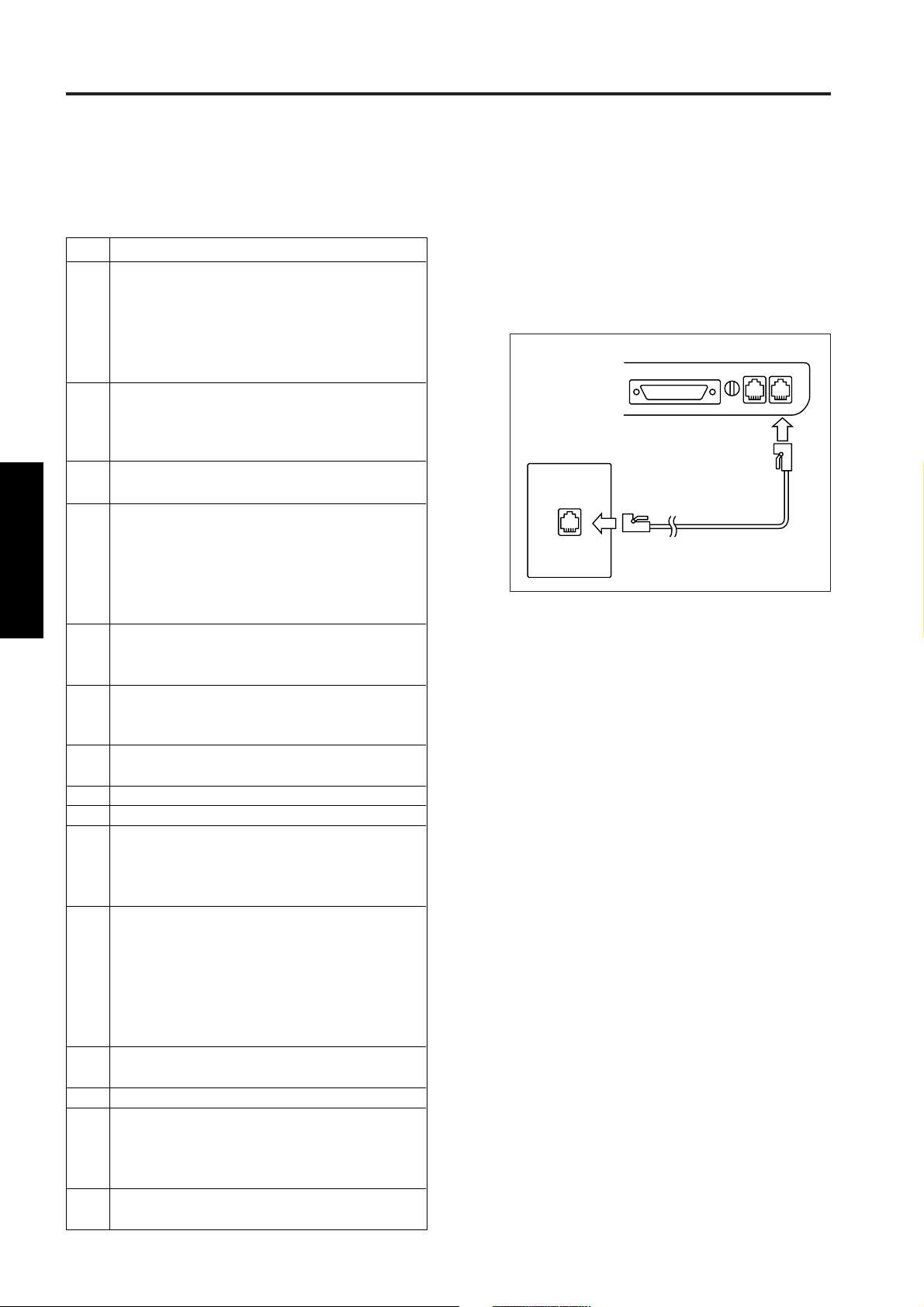
1
In case of a modem using, turn off the modem and
connect to the copier using a modem cable (RS-232C,
25P-25P straight cable) and wall jack using a modular
cable to the modem.
If the FAX KRDS is used, connect the FAX board
to the wall jack using the modular cable.
Setting the KRDS connection recognition
2
(25 mode → [1. Software SW])
Set copier software DIPSW 12-6 (KRDS
connection recognition) to “1”.
3
Initialize KRDS memory. (47 mode → [1] [5] [P]
[9] [8] [P] → Start button ON)
4
Set KRDS software SW.
(25 mode → [9. KRDS setting] → [4. KRDS software
SW set] (Select type of modem and dial mode))
3 KRDS
Select the type of modem from the bit pattern 0
to 6 of the KRDS software SW No.1 and dial
mode from the bit pattern 7.
5
Host password setting.
(25 mode → [9. KRDS setting] → [2. Host password
set]) (Refer to *1 and *2)
KRDS phone number setting.
6
(25 mode → [9. KRDS setting] → [3. KRDS TEL
No. setting]) (Refer to *3)
Turn off the SW1 (main power) and SW2 (sub
7
power) of the copier.
Turn on the power switch of the modem.
8
Turn on the SW1 (main power) of the copier.
9
Check the set up flag setting condition.
10
(25 mode → [9. KRDS setting] → [4. KRDS software
SW set] → check that the data on the switch No.33
and bit No.0 indicates “0” (not yet).)
11
Check the KRDS communication mode.
(25 mode → [9] KRDS Setting → [4] KRDS
software SW setting → Check the data in bit
No. 2 of switch No. 38.)
It should be set on “1” if communications are via FAXKRDS, and on “0” if communications are via a modem.
If the setting is different, change the setting.
12
Preform KRDS set up calling.
(25 mode → [9. KRDS setting] → [5. KRDS Setup calling])
13
Press the [START] key to start set up.
14
Check the finishing of set up.
(25 mode → [9. KRDS setting] → [4. KRDS software
SW set] → Completes if the data on the switch No.33
and bit No.0 indicates “1” (finished).)
15
Turn off the SW1 (main power) and SW2 (sub
power) of the copier.
*1: Host password must be 5-digit.
*2: Host password 1 must be specified.
*3: For both the copier and the host side, copier phone
number and host phone number 1 must be
specified.
*4: Refer to the manual of the modem about
specifications for connecting with the modular
cable.
LINETEL
Modem
Wall jack
Modular cable
Note: In the case of FAX KRDS, connect to the
LINE terminal on the FAX board.
3-2
Page 5
KRDS
Step
1
2
3
4
5
6
7
Operation procedure
Enter the 25 mode.
[25 mode menu screen]
Press the [9. KRDS setting ] key.
[KRDS setting menu screen]
Press the [4. KRDS software SW set] key.
[KRDS software SW set screen]
Use the [▲] or [▼] keys to set the switch number.
(Refer to *1)
Use the [▲] or [▼] keys to set the bit number.
(Refer to *1)
Press the [ON] of [OFF] key to set the bit data.
Press the [RETURN] key to end the setting.
1
2. Setting the KRDS connection recognition
(1) Plug the power cord of the copier to the outlet.
(When the SW1 (main power) and SW2 (sub
power) of the copier remain off.)
(2) Turn on the SW1 (main power) when the SW2 (sub
power) remains off.
(3) Turn on the SW2 (sub power) while pressing [2]
and [5] of the copy quantity setting buttons
simultaneously.
(4) Select the [1. Software SW] key on the 25 mode
menu screen.
(5) Select the bit No.6 of the switch No.12, and then
press the [ON] key.
ON: KRDS recognize
OFF: KRDS not recognized
Note: If the copier software DIPSW 12-6 (KRDS
recognition) is not selected to “1”, the
menu of the KRDS can not be selected.
3. Initializing KRDS memory
(1) Turn off the SW2 (sub power) when the SW1 (main
power) remains on.
(2) Turn on the SW2 (sub power) while holding down
[4] and [7] of the copy quantity setting buttons
simultaneously.
(3) Press the start print button after pressing the copy
quantity setting button [1], [5] and [P] button, then
[9], [8], finally [P] button again.
I/O check mode
< 15 - 98 > IN: – – OUT: NOW
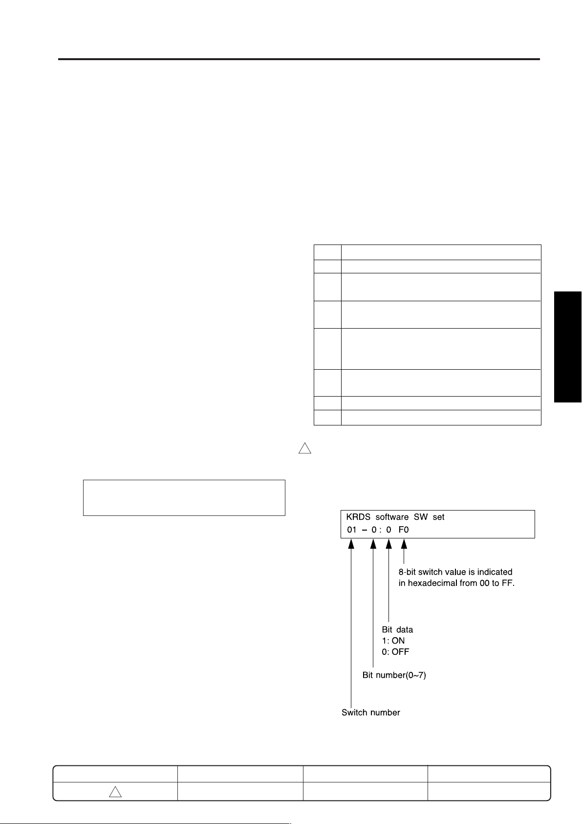
4. Setting KRDS software SW
This function allows adjustment of the KRDS software
switches.
Note: Adjust the software switch while checking
the switch and bit number since the
memory is rewritten every time the bit data
(1 or 0) is changed.
Any bit data that has been incorrectly
changed must be returned to the original
data.
3 KRDS
*1:
• The bit of the switch is written in the non-volatile
memory every time it is changed.
• The numbers shown in the message area are
defined as follows:
(4) “NOW” indication will be changed to “FIN” on the
message display.
(5) Turn off the SW2 (sub power).
REVISED EDITION
1
DATE
May 2000
3-3
For each switch function, refer to “List of KRDS
Software DIP SW”.
PA GE
3-3
METHOD
REPLACEMENT
Page 6

KRDS
5. Setting type of modem and line
(1) Using the switch No. 01, enter the modem and line
data into the bits 0 to 7, referring to the following
table.
<If telephone line type is “Pulse”>
Modem
intialization command
AT&FE0Q0V1X0S0=1&S0
AT&FE0Q0V1X0S0=1&S0&D2&C1
AT&FE0Q0V1X0S0=1&S0%E0
AT&FE0Q0V1X0S0=1&S0&D2
AT&FE0Q0V1X0S0=1&S0&M5
AT&FE0Q0V1X0S0=1
AT&FE0Q0V1X0S0=1&S0\N5
<If telephone line type is “Tone”>
Modem
3 KRDS
intialization command
AT&FE0Q0V1X0S0=1&S0
AT&FE0Q0V1X0S0=1&S0&D2&C1
AT&FE0Q0V1X0S0=1&S0%E0
AT&FE0Q0V1X0S0=1&S0&D2
AT&FE0Q0V1X0S0=1&S0&M5
AT&FE0Q0V1X0S0=1
AT&FE0Q0V1X0S0=1&S0\N5
Bit No.
Bit No.
7
6
5
4
3
2
1
0
*
0
0
0
0
0
0
0
1
01
0
0
0
0
0
0
1
0
02
0
0
0
0
0
0
1
1
03
0
0
0
0
0
1
0
0
04
0
0
0
0
0
1
0
1
05
0
0
0
0
0
1
1
0
06
0
0
0
0
0
1
1
1
07
0
1
2
3
4
5
6
7
0
0
0
0
0
1
0
0
0
0
0
1
0
0
0
0
0
1
1
0
0
0
0
1
1
0
0
0
0
1
1
0
0
0
0
1
1
0
0
0
0
1
*
1
81
0
0
82
1
1
83
1
0
84
0
1
85
0
0
86
1
1
87
1
Example:
If the initialization command for the modem you are
using is AT&FE0Q0V1X0S0=1&S0 and you have a
pulse-dial telephone line, enter the data for bits 7 to 0
as 00000001:
In hexadecimal <
Be sure to verify with the above charts whether or not
the hexadecimal <
model being used.
Reference:
This machine has a telephone (modem) line type
automatic recognition setting function.
KRDS Software DIP SW:
Switch No.38 and bit No.0
Data 0: off (manual setting)
on (line type automatic recognition) (default)
1:
As a result, if this switch is at “1”, Bit No. 7 of Switch No. 1 can
be either “0” or “1”.
>, the value is expressed as 01.
*
> output corresponds with the
*
3-4
Page 7
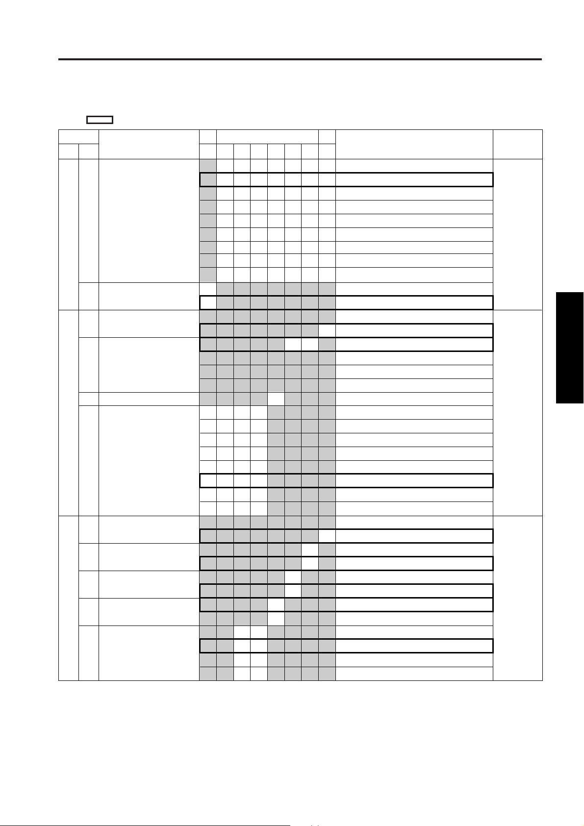
(2) List of KRDS Software DIP SW
: Default value
KRDS
byte
1
2
3
No.
bit
0-6
7
0
1-2
3
4-7
0
1
2
3
4-5
Function Description
Select modem
Dial mode
Data character length
Parity and stop bit
Reserve
Baud rate
Local echo
Result code
Result code form
(displayed result)
Set DCD signal operation
(carrier detect)
Set DSR signal operation
6
0
0
0
0
0
0
0
0
1
0
1
1
1
1
0
0
0
Function
5
4
0
0
0
0
0
0
0
0
0
0
0
0
0
0
0
0
1
1
1
1
0
0
0
1
1
0
1
1
0
0
0
1
1
0
0
0
0
1
1
0
1
1
3
0
0
0
0
0
0
0
0
1
Don’t
care
0
1
2
1
0
0
0
0
0
0
1
0
1
0
0
1
1
0
0
0
0
0
1
1
1
0
1
1
1
1
1
1
1
0
0
1
0
1
0
1
MSB LSB
7
0
1
0
0
0
0
0
1
1
1
Default value
(Hexadecimal)
No setting (No data is sent to modem.)
AT&FE0Q0V1X0S0=1&S0
AT&FE0Q0V1X0S0=1&S0&D2&C1
AT&FE0Q0V1X0S0=1&S0%E0
AT&FE0Q0V1X0S0=1&S0&D2
AT&FE0Q0V1X0S0=1&S0&M5
AT&FE0Q0V1X0S0=1
AT&FE0Q0V1X0S0=1&S0\N5
Manual setting (3 to 24 byte data is sent to modem.)
Pulse dial
Tone dial
8 bit (fixed)
No parity, stop bit 1 (fixed)
Even number of parity, stop bit 1
Odd number of parity, stop bit 1
No parity, stop bit 2
1200 bps
2400 bps
4800 bps
9600 bps
19200 bps
38400 bps
57600 bps
115200 bps
No setting
E0: Exist
No setting
Q0: Exist
No setting
V1: Word
No setting
&C1: ON only when the carrier is detected.
No setting
&S0: Keep ON
&S1: ON during online
&S2
(
(
(
81
*
81
*
57
*
)
)
)
3 KRDS
Note: In FAX-KRDS, items with the * mark are
disregarded (invalid).
3-5
Page 8

KRDS
No.
byte bit
3
4
3 KRDS
5
6
7
8
9
10
11
12
13
14
15
16
17
Function Description
6
Check DSR signal
7
Check DCD signal
0-1
Set DTR signal operation
Speaker control
2-3
Display speed when
4-6
connection is completed
and dial/busy tone is
detected.
Reset modem (This is set
7
prior to shipping.)
Arbitrary command regist-
0-7
ration area 1 (ASCII data)
0-7
0-7
Arbitrary command regist-
0-7
ration area 2 (ASCII data)
0-7
0-7
Arbitrary command regist-
0-7
ration area 3 (ASCII data)
0-7
0-7
Arbitrary command regist-
0-7
ration area 4
0-7
Command free setting
0-7
Set S register (bit 0 - 7)
0
Automatic receive ring count
S0:
S6:
1
2
Wait time from off hook
to dial start
S7: Off hook limit timer
6
0
1
0
0
0
0
1
1
1
1
Function
5
4
0
0
0
1
1
0
1
1
0
0
0
1
1
0
1
1
3
2
1
0
0
1
1
0
0
0
1
1
0
1
1
0
1
0
1
MSB LSB
7
0
1
0
1
0
off
on
off (fixed)
on
0
No setting
1
&D0
0
&D1
1
&D2
No setting
M0: Keep off
M1: ON until communication starts
M2
No setting
No indication of communication speed
X0:
X1: Indication of communication speed
Indication of communication speed; Detect dial tone
X2:
X3:
Indication of communication speed; Detect busy tone
X4:
Indication of communication speed; Detect dial and busy tone
non
non
No setting
&F: This is set prior to shipping.
Send ASCII data specified in this area to modem
0
No setting
1
S0=: Effective data
No setting
S6=: Effective data
No setting
S7=: Effective data
Default value
(Hexadecimal)
57
(
)
*
10
(
)
*
00
)
(
*
01
)
(
*
3-6
Page 9

KRDS
No.
byte bit
17
18
19
20
21
22
23
24
25
26
27
28
29
30
31
Function Description
S8: Dial stop time (sec.)
3
S9:
4
5
6
7
0
1
2
3
4
5
Carrier recognize time
S10: Allowable carrier
stop time
S11
Reserve
S0 data (No. of times data
was received automatically)
S6 data (Wait time until
dialing starts.)
S7 data (Wait time until
carrier detect)
S8 data (Pause time)
S9 data (Carrier detection
time)
S10 data (Carrier dis-
connection detection time)
S11 data
Timer 1 (Ring reception→
Connect reception)
Timer 2 (Dial call end
→ Connect reception)
Timer 3
Timer 4 (Line Connect → Send
Start-up message request)
Timer 5 (Opposite Party
Signal answer wait time)
Retry data; Timer 6
(Initialization OK →Dial call)
Call when SC error occurs
Call specify date
Call parts replace date
Call drum replace date
Call regular service date
6
0
1
Function
5
0
1
Don’t
care
4
3
0
1
0
1
00 - FFH
00 - FFH
00 - FFH
00 - FFH
00 - FFH
00 - FFH
00 - FFH
00 - FFH
00 - FFH
00 - FFH
00 - FFH
00 - FFH
00 - FFH
0
1
0
1
2
1
0
0
1
0
1
0
1
MSB LSB
7
Don’t
care
No setting
S8=: Effective data
No setting
S9=: Effective data
No setting
S10=: Effective data
No setting
S11=: Effective data
01H (1)
03H (3)
1EH (30)
03H (3)
06H (6)
0EH (14)
5FH(95)
20H (32) x 1sec
40H (64) x 1sec
0AH (10) x 100ms
20H (32) x 100ms
1EH (30) x 1sec
FFH (255) x 5ms
disable
enable
disable
enable
disable
enable
disable
enable
disable
enable
Default value
(Hexadecimal)
01
(
)
*
01 (
)
*
03 (
)
*
1E (
)
*
03 (
)
*
06 (
)
*
0E (
)
*
5F (
)
*
)
20 (
*
40 (
)
*
0A (
)
*
)
20 (
*
1E (
)
*
FF (
)
*
99
3 KRDS
3-7
Page 10

KRDS
No.
byte bit
31
32
33
3 KRDS
34
35
36
37
Function Description
Call regular transmit date
6
Select regular transmit
7
(Time and count)
Call when optional configu-
0
ration is changed
1
Report of toner
replenishment
2
Report of JAM occur
frequently
3-7
Reserve
0
Set up flag
1-2
Radial interval
3-4
Radial count
5-6
Reserve
7
Line feed control
(when initializing modem)
0-1
Call JAM date (main body)
Valid copy quantity
2-3
Call ADF JAM date
Valid original feed quantity
4-5
Call JAM date
MCBJ setting
6-7
Call JAM date
MOBJ setting
Reserve
Reserve
Reserve
0
1
Don’t care
0
0
1
1
0
1
0
1
Function
Don’t care
Don’t care
0
0
0
1
1
0
1
1
0
0
1
1
0
1
0
1
0
1
0
1
0
0
0
1
1
0
1
1
0
0
1
1
0
1
0
1
MSB LSB
76543210
0
1
0
1
0
0
1
1
disable
enable
time
counter
0
disable
1
enable
disable
enable
disable
enable
0
not yet
1
finished
1 min.
3 min.
5 min.
7 min.
0
5
10
No limit
CR/LF: LF exist
CR: No LF
0
Copy quantity: level 1
1
Copy quantity: level 2
0
Copy quantity: level 3
1
Copy quantity: level 4
Original feed quantity: level 1
Original feed quantity: level 2
Original feed quantity: level 3
Original feed quantity: level 4
MCBJ: level 1
MCBJ: level 2
MCBJ: level 3
MCBJ: level 4
MOBJ: level 1
MOBJ: level 2
MOBJ: level 3
MOBJ: level 4
Default value
(Hexadecimal)
99
00
0A
(*)
)
(
*
)
(
*
55
00
3-8
Page 11

KRDS
6
5
Don’t care
0
1
0
1
Don’t care
0
1
Bit pattern
43
0
1
Don’t
care
2
0
1
0
1
1
0
0
1
0
1
Don’t care
0
1
0
1
Default value
(Hexadecimal)
off
on
not connect
connect
DATA (Using a modem)
FAX
Upper 2-digit fixed (for host)
All 6-digit (for host)
Call back communication
No call back communication
copy enable
copy disable
copy enable
copy disable
disable
enable
disable
enable
disable
enable
Prohibition
Permission
No.
byte bit
38
Function Description
0
Line type automatic
MSB LSB
7
recognition
1
MSAD connection
2
KRDS communication
1)
0
1
39
mode (Note
3-5
Reserve
6
PM limit data length
7
Regular transmit communication
Sequence control
0-1
Reserve
2
RS-232 line error
K01_XX (Note 2)
3
Modem AT command error
K02_XX (Note 2)
4
Reserve
5
Force copy stop
(at host side) (Note 3)
Don’t care
40
6-7
Reserve
0
Force copy stop (Note 3)
(at terminal equipment side)
Jam history data clear
1
Reserve
2-5
User data access setting
6
(local) (Note 4)
Resarve
7
Note 1: KRDS Communications Mode (38 Byte, 2 bit) : This bit is set on “1” when the FAX option is connected and
1
0
when the KRDS memory initialization operation is performed.
88
(*)
00
3 KRDS
00
Note 2: For details of errors, refer to [10] Error code table.
1
Note 3: Copy prohibition: If DIP SWs 39-5 and 40-0 are both set to 1, then it becomes impossible to copy.
1
Note 4: There are three types of user data, speed dial data, programmed dial data and group dial data. Normally, due
to maintenance of the confidentiality of user data, access to these data by service personnel is, as a rule,
prohibited. If for any reason, access is necessary using KRDS, this switch can be changed to ‘1’, then access
will be enabled. In this case, change the settings after obtaining the agreement of the customer.
6. Setting host password
This function sets the host password.
(1) Screen selection
Select the [9. KRDS setting] key in the 25 mode menu screen to display the KRDS setting menu screen as an initial
screen.
Then select the [2. Host password set] key to display the host password setting screen.
REVISED EDITION
DATE
PA GE
METHOD
3-9
1
May 2000
3-9
REPLACEMENT
Page 12

KRDS
(2) Setting method
a. Three patterns can be used to set KRDS host
password. The entry screen, screen contents and
setting method for each pattern are all the same.
Each message, however, is different.
(There are only 2 patterns for a usable password.)
b. Press the [NEXT] or [BACK] key to 2change the
screen.
c. Enter the host password, 5-digit number or
alphabet, with the numeric keys on the screen and
press the [SET] key.
d. The firstly entered number or alphabet will be
shifted to the left end.
e. After inputting the password, it the [NEXT], [BACK]
or [RETURN] key is pressed before pressing the
key, the data that has been entered is canceled.
f. Press the [SET] key, and then press the
[RETURN] key to set the entered password. The
screen will return to the KRDS setting menu
screen.
3 KRDS
* As the host password is set to “00000” in factory
setting, ensure to change it to the password which
was set by the KRDS host application for
communication.
Confirm the password of host side with KRDS host
application administrator.
* Note that the host password setting (Host 1) must
be performed.
* See the [5] Calling time set menu mode (Arbitrary)
1
concerning “Host 2” settings.
* Do not care “Host 3.”
Operation procedure
Step
Enter the 25 mode.
1
[25 mode menu screen]
2
Press the [9. KRDS setting ] key.
[KRDS setting menu screen]
3
Press the [2. Host password set] key.
[Host password setting screen]
4
Enter password consisting of number and
alphabet.
Press the [NEXT] or [BACK] key to change the
5
screen, then enter password (up to 2 patterns).
Press the [SET] key.
6
Press the [RETURN] key to end the setting.
7
REVISED EDITION
1
DATE
May 2000
3-10
PA GE
3-10
METHOD
REPLACEMENT
Page 13

KRDS
7. Setting the KRDS telephone number
This function sets copier for KRDS and host telephone
number.
(1) Screen selection
Select the [9. KRDS setting] key in the 25 mode menu
screen to display the KRDS setting menu screen as
an initial screen.
Then select the [3. KRDS TEL No. Setting] key to
display the KRDS TEL NO setting screen.
(2) Setting method
a. Three patterns can be used to set KRDS phone
number. The entry screen, screen contents and
setting method for each pattern are all the same.
Each screen, however, is different.
b. Press the [NEXT] or [BACK] key to change the
screen.
c. Enter the telephone number, 15-digit or less
number, with the numeric keys on the screen and
press the [SET] key.
d. The entered number is displayed in the cursor
section displayed in the line 2 of the message
display area. The cursor shifts from left to right
according to the entered.
If more than 15 digit is entered, the number of the
15 digit is rewritten.
e. To reenter the telephone number, press the Stop/
clear button to clear the data then enter the correct
number.
f. If you wish to change the number of an arbitrary
position, press the [<<] or [>>] key to move the
cursor to the desired position and reenter.
g. No data has been set for the second row of the
message area prior to shipping.
h. The keys except the numeric keys are defined as
follows:
[,] Pause:
Wait temporarily for self-dial feed. (2-3 sec.)
[W] Wait:
Wait for dial tone such as asynchronous,
etc. (excluding sound guidance).
[T] Tone Dial:
Indicate tone dial after this symbol
[P] Pulse Dial:
Indicate pulse dial after this symbol
[-] Symbol to divide numbers:
(This symbol is ignored when dialing.)
[ . ], [#], [
i. After inputting the password, it the [NEXT], [BACK]
or [RETURN] key is pressed before pressing the
[SET] key, the data that has been entered is
canceled.
j. Press the [SET] key, and then press the [BACK]
key to set the entered number. The screen will
return to the KRDS setting menu screen.
* • Note that the telephone number setting (copier)
• Refer to [5] Calling time set menu mode
1
• Do not care "Host 3."
Step
Operation procedure
1
Enter the 25 mode.
2
[25 mode menu screen]
Press the [9. KRDS setting ] key.
3
[KRDS setting menu screen]
Press the [3. KRDS TEL No. setting] key.
4
[KRDS TEL No. setting screen]
Enter telephone number (15-digit or less) consisting
of number and alphabet with numeric keys.
Press the [NEXT] or [BACK] key to change the
5
screen, then telephone number (up to 3 patterns).
Press the [SET] key.
6
Press the [RETURN] key to end the setting.
7
]:
*
Use these keys as required such extension
number.
and telephone number setting (Host1) must be
performed.
(Arbitrary) for the (Host 2).
3 KRDS
REVISED EDITION
1
DATE
May 2000
3-11
PA GE
3-11
METHOD
REPLACEMENT
Page 14

KRDS
8. Calling KRDS set up
<Auto set up>
In the host call setting, call the designated host computer
in the set date and time, and transmit each data of the
copier. Refer to the separate KRDS Host Application
Manual for details of the data being handled.
(1) Screen selection
Select the [9. KRDS setting] in the 25 mode menu
screen to display the KRDS setting menu screen.
Then select the [4. KRDS software SW set] to display
the KRDS software SW set screen.
Check that the software DIP SW 33-0 is set to “0”.
After checking, press the [RETURN] key to return to
the KRDS setting menu screen.
On the KRDS setting menu screen, select the [5.
KRDS Setup calling] to display the calling host for
setup screen.
Note: If the KRDS software DIPSW 33-0 (Set up
3 KRDS
flag) is not selected to “0” (not yet). The
KRDS setup calling screen can not be
selected.
c. Turn off the power to end the operation.
Step
Operation procedure
1
Enter the 25 mode.
2
[25 mode menu screen]
Press the [9. KRDS setting ] key.
3
[KRDS setting menu screen]
Press the [4. KRDS software SW set] key.
4
[KRDS software SW set screen]
Use the [▲] , [▼] key to select the switch number
to “33” and bit number “0”.
5
Check that bit data indicates “0”. If not, set to “0”
to press the [OFF] key.
6
Press the [RETURN] key to return to the KRDS
setting menu screen.
7
[KRDS setting menu screen]
Press the [5. KRDS Setup calling] key.
8
[Calling the host for setup screen]
Press the [Start] key.
Check the message on the screen.
9
Turn off the power to end the operation.
• How to confirm the completion of setup
(2) Setting method
a. Press the [Start] key in the screen.
(a) Communication message
Calling the host for setup
Communicating
Note: Do not turn OFF the power during
communication.
(b) Completion message
Calling the host for setup
Communication completed
b. Turn off the power if no completion message is
displayed in ten minutes.
Check that the host computer starting up correct,
host phone number, cable connection, etc. then
open to calling the host for setup screen again to
press the [Start] key.
Confirm the data at bit No. 0 of address 33 in
reference to "4. Setting KRDS software DIP SW."
If "0", setup is not completed.
If "1", setup is completed.
<Manual set up>
This copier machine can be set up manually, other
than the automatical setup as explained above. (The
setup is effective when both the copier and the host
have completed the setup action.)
• Operation for the copier machine
1. Switch on the power of modem.
2. Set the address No. 33 as referring to "4. Setting
KRDS software DIP SW."
3. Change the data of bit No. 0 from 0 to 1.
0: Set up not completed
1: Set up completed
4. Establish the changed data by pressing the copy
button.
5. Switch off the power of main body.
• Operation for the host computer
3-12
For the operation of the host compouter, refer to the
KRDS Host Application Administrator's Manual.
Page 15

KRDS
[5]
Calling time set menu mode (Arbitrary)
Select the [9. KRDS setting] key in the 25 mode menu
screen to display the KRDS setting menu screen as an
initial screen.
Then select the [1. Calling time set] key to display the
calling time set menu screen.
Calling time set menu
1. Calling mode-1
2. Calling mode-2
3. Calling mode-3
Press the [RETURN] key to exit the calling time set menu
screen and return to the KRDS setting screen.
This host calling setting calls everything to the “Host
*
2”.
Therefore, it is necessary first to set the “Host 2”
telephone No. and host password.
1. Setting calling time setting mode
This function sets designated date calling.
(1) Screen selection
Select the [1. Calling mode-1] (Setting designated
date calling setting) in the calling time set menu
screen to display the calling mode-1 (designated date
calling) setting screen.
Press the [RETURN] key to exit the calling mode-1
(designed date calling) setting screen and return to
the calling time set menu screen.
(2) Entering method
a. Enter year, month, day and time using the numeric
keys.
b. The cursor that indicates entering position will be
appeared in the message indication area at line 2.
c. Using the [<<], [>>] key and move the cursor to
desired position.
d. If reenter the entered data, press the Stop/clear
button to clear the entered data then enter the data
again.
e. Enter year, month, day and time using the numeric
keys, then press the [SET] key.
f. Enter year, month, day and time as follows.
• The year is entered by inputting 4-digit in the
Christian era.
• The month and day are entered by inputting 2-digit
number. (Example: 1 is entered as 01.)
• The time is entered using 24 hour clock.
(Example: 1:00p.m. is entered as 13.)
• The minute is entered by inputting 2-digit number.
(Example: 1 is entered as 01.)
• Example:
at 1:00 p.m. of January 15, 1998 →
1998/01/15 13:00
g. Press the [SET] key every time data for one item is
entered and check the entered data.
h. The screen will return to the calling time setting
menu screen if the [RETURN] key is pressed
without pressing the [SET] key. In this case, no
entered data will be changed.
3 KRDS
3-13
Page 16

KRDS
Step
1
2
3
4
5
6
3 KRDS
7
i. Press the [SET] key, and then the [RETURN] key
to end setting. The screen will return to the calling
time set menu screen.
Operation procedure
Enter the 25 mode.
[25 mode menu screen]
Press the [9. KRDS setting ] key.
[KRDS setting menu screen]
Press the [1. Calling time set] key.
[Calling time set menu screen]
Use the [1. Calling mode-1] (Setting designated
date calling setting).
[Calling mode-1 (Designed date calling)
setting screen]
Enter year, month and day using the numeric
key on the screen, then press the [<<], [>>] key
to move the cursor to entering position of time.
Enter time and minute using the numeric keys on
the screen, then press the [SET] key.
Press the [RETURN] to end the setting.
2. Setting regular date & time calling
The copier will call the host at the regular time
specified.
(1) Screen selection
Select the [2. Calling mode-2] (regular data & time
calling setting) in the calling time set menu screen to
display the calling mode-2 (regular data & time
calling) setting screen.
Press the [RETURN] key to exit the calling mode-2
(regular data & time calling) setting screen and return
to the calling time set menu screen.
(2) Mode selecting method
a. Select and press the desired mode in the
[monthly], [weekly], [dayly] keys.
There are three mode type (month, week, day)
that can be set.
b. The current selected mode is high lighted
according to the mode key.
At this time, the setting contents will be appeared
in the message indication area at line 2.
3-14
Page 17

KRDS
Step
1
2
3
4
5
6
7
8
Operation procedure
Enter the 25 mode.
[25 mode menu screen]
Press the [9. KRDS setting ] key.
[KRDS setting menu screen]
Press the [1. Calling time set] key.
[Calling time set menu screen]
Use the [2. Calling mode-2] (regular time calling
setting).
[Calling mode-2 (regular time calling) setting
screen]
Press the any key in [monthly], [weekly], [daily]
keys.
Using the numeric keys on the screen, enter the
day, hour and minute.
(Item that can be input differs from depend on
the mode.)
Press the [SET] key.
Press the [RETURN] to end the setting.
(3) Mode setting method
Perform the operation in each mode as follows:
a. Monthly mode
(a) Using the numeric keys, enter the day, hour
and minute.
(b) Press the [SET] key to enter the input data.
b. If you wish to change the number of an arbitrary
position, press the [<<] or [>>] key to move the
cursor to the desired position and reenter.
c. If reenter the entered data, press the Stop/clear
button to clear the entered data then enter the data
again.
d. Weekly mode
(a) Using the numeric keys, enter the day of the
week, hour and minute.
(b) The day of the week is entered using the
numeric keys according to the following
definitions.
1: Monday 2: Tuesday 3: Wednesday
4: Thursday 5: Friday 6: Saturday
7: Sunday
(c) Press the [SET] key to enter the input data.
e. Daily mode
(a) Using the numeric keys, enter the hour and
minute.
(b) Press the [SET] key to enter the input data.
f. Common operation
(a) The screen will return to the calling time set
menu screen if the [RETURN] key is pressed
without pressing the [SET] key. In this case, no
entered data will be changed.
(b) Press the [SET] key, and then the [RETURN]
key to end setting. The screen will return to
calling time set menu screen.
(c) Enter the number with the numeric keys as
follows:
• The month and day are entered by inputting 2-digit
number. (Example: 1 is entered as 01.)
• The time is entered using 24 hour clock.
(Example: 1:00p.m. is entered as 13.)
• The time is entered using 24 hour clock. (Example:
1:00p.m. is entered as 13.)
• Example:
Monthly mode: 10 17:10
Weekly mode: day 17:10
Daily mode: 17:10
3 KRDS
3-15
Page 18

KRDS
3. Setting regular count calling
The copier will call the host at the regular count
specified.
(1) Screen selection
Select the [3. Calling mode-3] (regular count) in the
calling time set menu screen to display the Calling
mode-3 (regular count call) setting screen.
Press the [RETURN] key to exit the Calling mode-3
(Regular count call) setting screen and return to the
calling time set menu screen.
(2) Setting method
a. Using the numeric keys on the screen, enter 6-
digit number, regular count value, then press the
[SET] key.
b. To reenter the entered data, press the Stop/clear
button to clear the entered data then enter the data
again.
3 KRDS
c. The entered numerical value is entered from the
number of 4 digit. The number is displayed while
shifting from right to left.
d. The screen will return to the calling time set menu
screen if the [RETURN] key is pressed without
pressing the [SET] key. In this case, no entered
data will be changed.
e. Press the [SET] key then the [RETURN] key to
end the setting. The screen will return to the calling
time set menu screen.
[6] KRDS host call
If the machine is connected to a KRDS, it can call the host
at the service center.
a. Select the [JAM history] (JAM-related trouble call),
[SC history] (SC-related trouble call), [No TONER],
[No PAPER], [COPY QUALITY] (Copy qualityrelated trouble call) or [OTHER REASON] (Other
call), depending upon the particular circumstances.
KRDS host menu
1. JAM history
2. SC history
3. NO TONER
4. NO PAPER
5. COPY QUALITY
6. OTHER REASON
b. When the [Start] key is pressed, the machine starts
calling the host.
Caution: Do not turn OFF the power during
communication.
Step
Operation procedure
1
Enter the 25 mode.
2
[25 mode menu screen]
Press the [9. KRDS setting ] key.
3
[KRDS setting menu screen]
Press the [1. Calling time set] key.
4
[Calling time set menu screen]
Use the [3. Calling mode-3] (regular count).
5
[Calling mode-3 (regular count call) setting
screen]
Using the numeric keys on the screen, enter
number, regular count value, then press the
[SET] key.
6
Press the [RETURN] to end the setting.
3-16
Page 19

KRDS
[7] FAX KRDS auto on function
1
If the FAX option is installed, the FAX-KRDS mode
automatically becomes effective when the main power is
turned ON.
(Mode 25 → Software DIP SW12–6:1 (continuous)
KRDS software DIP SW 38-2: Set on 1 (FAX).)
Even if the FAX option is installed, if the FAX KRDS
function is not used, (if a modem is used), the above FAX
KRDS auto on function is deactivated by changing the
settings below.
However, in [8] “Setting the Serial number” in 25 Mode, if
the “Destination” setting is DE: German, FAX KRDS mode
does not become valid even if the FAX option is installed.
Step
Operation procedure
1
Enter the key operator mode.
2
[Key operator mode menu screen]
Press the FAX setting key and display the FAX
setting menu.
3
[FAX setting menu screen]
Press the special setting key and display the
password input screen.
4
Input the password [9] [2] [7] [2], then press the
[OK] key.
5
[FAX setting menu screen]
Press the nonvolatile parameters key.
6
[Nonvolatile parameter setting screen]
Press the function parameters setting key.
7
Turn address 0E0138: bit 0 (Auto On/Off function
for FAX KRDS) OFF.
Refer to FK-101 Service Handbook for more detail.
[8] A point to notice for operation
Be sure to turn ON the main power of the copier if the modem
1
power is turned OFF and ON with the main power OFF.
Reason: To initialize the modem.
(When the KRDS circuit is powered, it automatically
initialized the modem following the modem power ON and
OFF operations.
When the main power of the copier is OFF, however, the
1
KRDS circuit is not powered and does not initialize the
modem after the modem power ON and OFF operations.
Some types of modem cannot start communication with
KRDS unless they are initialized by the KRDS.)
3 KRDS
REVISED EDITION
1
DATE
May 2000
3-17
PA GE
3-17
METHOD
REPLACEMENT
Page 20

KRDS
[9] ASCII code table
ASCII is 1 byte code specified by ANSI.
It enables indication of control code, alphabet and number.
3 KRDS
character
SH
SX
EX
ET
EQ
AK
BL
BS
HT
LF
HM
CL
CR
S0
S1
DE
D1
D2
D3
D4
NK
SN
EB
CN
EM
SB
EC
→
←
↑
↓
binary
0000 0000
0000 0001
0000 0010
0000 0011
0000 0100
0000 0101
0000 0110
0000 0111
0000 1000
0000 1001
0000 1010
0000 1011
0000 1100
0000 1101
0000 1110
0000 1111
0001 0000
0001 0001
0001 0010
0001 0011
0001 0100
0001 0101
0001 0110
0001 0111
0001 1000
0001 1001
0001 1010
0001 1011
0001 1100
0001 1101
0001 1110
0001 1111
hexa-
decimal
0
1
2
3
4
5
6
7
8
9
A
B
C
D
E
F
10
11
12
13
14
15
16
17
18
19
1A
1B
1C
1D
1E
1F
character
!
"
#
$
%
&
'
(
)
*
+
,
-
.
/
0
1
2
3
4
5
6
7
8
9
:
;
<
=
>
?
binary
0010 0000
0010 0001
0010 0010
0010 0011
0010 0100
0010 0101
0010 0110
0010 0111
0010 1000
0010 1001
0010 1010
0010 1011
0010 1100
0010 1101
0010 1110
0010 1111
0011 0000
0011 0001
0011 0010
0011 0011
0011 0100
0011 0101
0011 0110
0011 0111
0011 1000
0011 1001
0011 1010
0011 1011
0011 1100
0011 1101
0011 1110
0011 1111
hexa-
decimal
20
21
22
23
24
25
26
27
28
29
2A
2B
2C
2D
2E
2F
30
31
32
33
34
35
36
37
38
39
3A
3B
3C
3D
3E
3F
character
@
A
B
C
D
E
F
G
H
I
J
K
L
M
N
O
O
Q
R
S
T
U
V
W
X
Y
Z
[
¥
]
^
_
binary
0100 0000
0100 0001
0100 0010
0100 0011
0100 0100
0100 0101
0100 0110
0100 0111
0100 1000
0100 1001
0100 1010
0100 1011
0100 1100
0100 1101
0100 1110
0100 1111
0101 0000
0101 0001
0101 0010
0101 0011
0101 0100
0101 0101
0101 0110
0101 0111
0101 1000
0101 1001
0101 1010
0101 1011
0101 1100
0101 1101
0101 1110
0101 1111
hexa-
decimal
40
41
42
43
44
45
46
47
48
49
4A
4B
4C
4D
4E
4F
50
51
52
53
54
55
56
57
58
59
5A
5B
5C
5D
5E
5F
character
‘
a
b
c
d
e
f
g
h
i
j
k
l
m
n
o
p
q
r
s
t
u
v
w
x
y
z
{
}
~
binary
0110 0000
0110 0001
0110 0010
0110 0011
0110 0100
0110 0101
0110 0110
0110 0111
0110 1000
0110 1001
0110 1010
0110 1011
0110 1100
0110 1101
0110 1110
0110 1111
0111 0000
0111 0001
0111 0010
0111 0011
0111 0100
0111 0101
0111 0110
0111 0111
0111 1000
0111 1001
0111 1010
0111 1011
0111 1100
0111 1101
0111 1110
0111 1111
hexa-
decimal
60
61
62
63
64
65
66
67
68
69
6A
6B
6C
6D
6E
6F
70
71
72
73
74
75
76
77
78
79
7A
7B
7C
7D
7E
7F
3-18
Page 21

[10] Error code table
Error code CountermeasureContents
1
K00_00
K00_01
K00_02
K00_03
K00_04
K00_05
K00_06
K00_07
K00_08
K00_09
K00_10
K00_11
K00_12
K00_13
K01_00
K01_01
K01_02
K01_03
K02_00
K02_01
Connection NG.
No response from other party.
(No detection of start text from host after establishing connection.)
Because copying is taking place, it is impossible to write to the
non-volatile memory and the line is cut.
Password does not match.
Serial number does not match.
Syntactical error.
Write-in indication on an item for which write-in is impossible.
Unread item error.
Signal reception time-out after detection other party response.
Serial number registration completed.
Communications error due to generation of carrier OFF.
Dial tone is not detected within 5 seconds after setting of
x2 and x4 commands.
Busy signal detected.
No tone detected for 5 seconds after input of @ command.
DTR went to OFF or in OFF state.
Cannot open RS-232C.
Cannot close RS-232C.
Response time-out from RS-232C task.
AT command error.
Initializing NG (MODEM).
Example: Modem initializing command no good.
KRDS
Redial, repeat reception standby.
Redial, repeat reception standby.
Temporarily stop copying.
Check password.
Check serial number.
Redial, repeat reception standby.
Re-operation on host side.
Re-operation on host side.
Redial, repeat reception standby.
Check serial number.
Redial, repeat reception standby.
Check connection of telephone
line.
Redial.
Redial, repeat reception standby.
Check modem power source.
Check RS-232C cable connection.
Turn power on copier OFF and ON.
Turn power on copier OFF and ON.
Check modem power source.
Check RS-232C cable connection.
Turn power on copier OFF and ON.
Possibility of modem malfunction
or software bug.
Check modem power source.
Check RS-232C cable connection.
3 KRDS
REVISED EDITION
1
DATE
May 2000
3-19
PA GE
3-19
METHOD
REPLACEMENT
Page 22

3 KRDS
Blank page
 Loading...