

Page 1

DF-314
SERVICE HANDBOOK
2001.02
Ver. 3.0
KONICA CORPORATION
TECHNOLOGY SUPPORT CENTER
TOKYO JAPAN
Page 2

KONICA CORPORATION
COPYRIGHT ©2001
CN26NF1780
Page 3
CONTENTS
1
CONTENTS
SAFETY AND IMPORTANT WARNING ITEMS .............
Refer to the 7020/25/30/35 service handbook on page C-1
2
1. OUTLINE
DF-314 PRODUCT SPECIFICATIONS .................. 1-1
[1] Type ........................................................ 1-1
[2] Functions ................................................ 1-1
[3] Machine data .......................................... 1-1
[4] Maintenance ........................................... 1-1
[5] Machine environment ............................. 1-1
CENTER CROSS SECTION ..................................1-2
DRIVE SYSTEM DIAGRAM ................................... 1-3
ORIGINAL CONVEYANCE PROCESS ................. 1-4
[1] Single-side original copy mode ............... 1-4
[2] Double-side original copy mode ............. 1-5
[3] Mixed original copy mode ....................... 1-5
2. UNIT EXPLANATION
EXTERNAL SECTION ........................................... 2-1
[1] Composition ............................................ 2-1
[2] Mechanisms ........................................... 2-1
ORIGINAL FEED/REVERSAL/ORIGINAL EXIT
SECTION ............................................................... 2-2
[1] Composition ............................................ 2-2
[2] Mechanisms ........................................... 2-2
[3] Original feed/conveyance/scan control ... 2-3
[4] Original exit/reversal and conveyance
control ..................................................... 2-5
[5] Original size detection control ................ 2-7
1 OUTLINE
2 UNIT EXPLANATION
3
Assembly
3 DIS./ASSEMBLY
3. DISASSEMBLY/ASSEMBLY
DISASSEMBLY/ASSEMBLY .................................. 3-1
[1] Replacing feed roller/A ........................... 3-1
[2] Replacing the double-feed prevention
roller/A assy ............................................ 3-1
[3] Replacing the read roller ........................ 3-2
[4] Removing and attaching the paper dust
2
removing brush ....................................... 3-3
REVISED EDITION
2
DATE
Feb. 2001
PA GE
–
METHOD
REPLACEMENT
Page 4

1
1 OUTLINE
2
Unit
2 UNIT EXPLANATION
3
Assembly
3 DIS./ASSEMBLY
Blank page
Page 5

1
OUTLINE
1 OUTLINE
2 UNIT EXPLANATION
3 DIS./ASSEMBLY
Page 6

1 OUTLINE
2 UNIT EXPLANATION
3 DIS./ASSEMBLY
Blank page
Page 7
DF-314 PRODUCT SPECIFICATIONS
DF-314
[1] Type
Type:
Sheet-through Type reversible
DF
[2] Functions
Originals Size:
2
Original Type
Plain Original: 35g/m
Special Original: Original feed and convey-
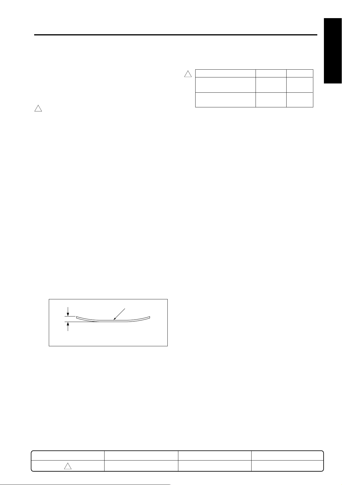
Original Curling: 10mm maximum (35g/m
A3, B4, A4, A4R, B5, A5,
A5R, B5R, B6R, 11x17,
8.5x14, F4, 8.5x11, 8.5x11R,
5.5x8.5, 5.5x8.5R
• Only single-side mode is
available with B6R
• All sizes are detected
automatically.
• Mixing of original size
possible.
2
- 130g/m2 fine quality
original
ance ability may be inferior
those of 35g/m
fine quality original.
The following types of original
cannot be used:
• OHP film
• Blueprint masters
• Offset masters
• Bonded original
130g/m
2
high-quality paper)
Original
2
to 130g/m
2
to
Original scan speed (copies per minute)
Mode 7020/25/30 7035
2
Single sided Original → 30 35
Single sided Copy
Double sided Original → 18 18
Double sided Copy
Original Feed Layout:
Face-up placement, centre
standard
Original image read Position:
At the slit glass section
1 OUTLINE
2 UNIT EXPLANATION
[3] Machine data
Power Source: DC24V/5V (supplied from the
main body)
Max. Power Consumption:
Max.100VA
Weight: Approximately 10.7kg
2
Machine Dimensions: Length 576mm
(including about 1.1kg for
platen)
Depth 498mm
Height 100mm
(Excluding the original feed tray)
3 DIS./ASSEMBLY
[4] Maintenance
Maintenance: Same as the main unit
Machine Life: Same as the main unit
Curling
Maximum number of stacked originals:
50 sheets Maximum (80g/m2)
REVISED EDITION
2
DATE
Feb. 2001
[5] Machine environment
Temperature: 10 to 30˚C
Humidity: 20 to 80%RH
Note: Specifications are subject to change without
notice.
PA GE
1-1
1-1
METHOD
REPLACEMENT
Page 8
DF-314
1
CENTER CROSS SECTION
1 OUTLINE
2 UNIT EXPLANATION
3 DIS./ASSEMBLY
1
Reversal guide
Original conveyance
rollers
Registration roller
Read-out roller
Separation roller
Original feed roller
Paper lift-up plate
Double feed prevention roller
Reversal roller
Original exit roller
Exit guide
REVISED EDITION
1
DATE
May 2000
1-2
PA GE
1-2
METHOD
REPLACEMENT
Page 9
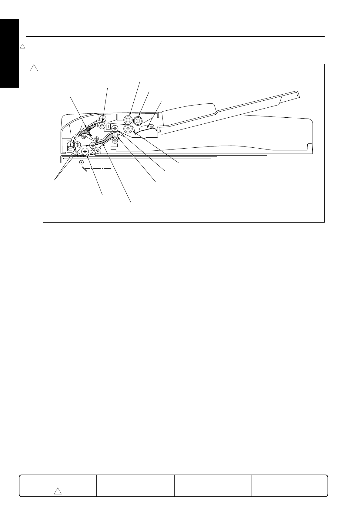
DRIVE SYSTEM DIAGRAM
DF-314
1
Original conveyance motor (M302)
Original feed motor (M301)
Original reversal motor (M303)
Original exit roller
Exit guide
Registration
roller
Double feed
prevention roller
Reversal guide
1 OUTLINE
Separation roller
Original feed roller
Paper lift-up plate
Feed drive
Reversal roller
2 UNIT EXPLANATION
Reversal drive
Roller pressure SD (SD302)
3 DIS./ASSEMBLY
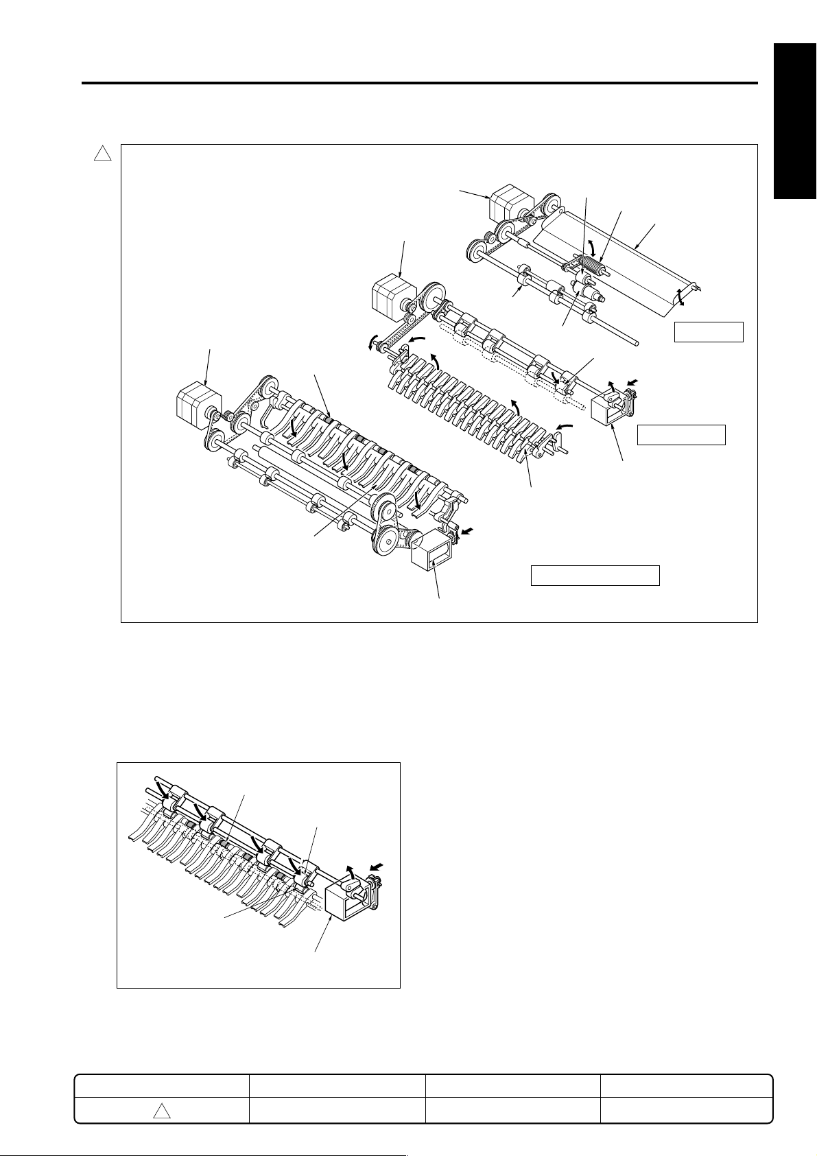
*Reversal and Exit Rollers
A reversal roller pulley is attached to the original
exit roller shaft. The reversal roller conveys the
original through pressure being applied on the
pulley by the roller pressure SD.
Original exit roller
Reversal roller
Pulley
Roller pressure SD (SD302)
Conveyance/exit drive
Exit SD (SD303)
REVISED EDITION
1
DATE
May 2000
1-3
PA GE
1-3
METHOD
REPLACEMENT
Page 10

DF-314
ORIGINAL CONVEYANCE PROCESS
As illustrated below, the DF-314 is made up of a original
1 OUTLINE
feed section, conveyance section, original exit section and
reversal section.
Original feed section
Reversal section
Original exit section
Platen glass
2 UNIT EXPLANATION
1
Conveyance
section
Slit glass
(Read section)
With the originals set face-up on the original feed tray,
they are fed from the topmost original. Rather than being
conveyed to an original glass surface, the originals that
are fed in and read when they pass a slit glass placed in
the conveyance path.
The operation mode of the DF-314 consists of 3 modes,
3 DIS./ASSEMBLY
the one-side original copy mode, the two-side original
copy mode and the mixed original copy mode.The
conveyance method differs for each mode.
[1] Single-side original copy mode
When PS311 turns ON, the original is re-fed by the
registration roller and conveyed to the original conveyance
roller. The original conveyance roller conveys the original
to the position where PS312 (original feed PS) turns ON.
Conveyance rollers
Original feed PS
(PS312)
Registration roller
Original registration
PS (PS311)
The conveyance roller turns, and scanning starts. If there
is another original waiting, it is pre-fed at this point.
The scanning of the original is conveyed out when the
original passes over the slit glass. The original which has
been read is exited to the original exit tray by the original
exit roller with the exit SD OFF (i.e. with the exit guide
raised).
Next original
(Single-side→single-side copy, single-side→doubleside copy)
The original that has been set in the paper feed tray is
lifted by the paper lift-up plate so it comes into contact with
the original feed roller. The original feed roller and the
separation roller pre-feed to the position where P311
(original registration PS) turns on.
Separation roller
Registration roller
Original registration PS (PS311)
Original feed roller
Paper lift-up plate
Slit glass
Original exit roller
Exit guide
REVISED EDITION
1
DATE
May 2000
1-4
PA GE
1-4
METHOD
REPLACEMENT
Page 11

DF-314
[2] Double-side original copy mode
(Double-side→single-side copy, double-side→
double-side copy)
The original set in the original feed tray is pre-fed to the
position where PS311 (original registration PS) turns ON
by the original feed roller and the separation roller. When
PS311 turns ON, the reversal guide opens, the
registration roller conveys the original to the reversal
section, and the reversal roller conveys the original into
the interior of the reversal section.
Reversal guide
Original registration PS (PS311)
After the specified period from when PS311 detects the
1
trailing edge of the original and goes OFF, the original is
conveyed to the stop position at the front edge of the
reversal guide. As the original has been reversed at this
point, the reversal roller is made to rotate in reverse and it
conveys the original to the original conveyance roller. If
there is another original waiting, it is pre-fed at this timing.
Registration roller
Reversal roller
The exit SD comes ON (the exit guide is lowered) when
scanning of the rear side of the original begins, and the
original is again conveyed to the reversal roller. When
PS312 detects the rear edge of the original and turns OFF,
the original is conveyed as far as the stop position in front
of the reversal gate by the timer. The original has been
reversed once again by this point so is conveyed to the
original conveyance roller. The original conveyance roller
conveys the original and reading of the oliginal face side
starts.
Flapper
Original conveyance
PS (PS312)
Next original
Reversal roller
Exit guide
Slit glass
The original which has been read is exited to the original
exit tray by the original exit roller with the exit SD OFF (i.e.
with the paper exit guide raised). If there is another
original, it is conveyed to the reversal section at this point.
Next original
Reversal roller
1 OUTLINE
2 UNIT EXPLANATION
3 DIS./ASSEMBLY
The original conveyance roller conveys the original to the
position where PS312 turns ON and the reading of the
original back side starts.
1
Reversal guide
Flapper
Conveyance roller
Next original
Reversal roller
Exit roller
Slit glass Exit guide
[3] Mixed original copy mode
The mixed original copy mode supports both same-series
originals and different series originals, but as size
detection is performed in PS311 ON time, size detection is
performed before reading.
After the size of the original is detected, the original stops
1
at the reversal position. Subsequently, operation is the
same as that of the two-sided copy mode.
Refer to "ORIGINAL FEED/REVERSAL/ORIGINAL EXIT
SECTION [5] Original size detection control" for size
detection operation.
REVISED EDITION
1
DATE
May 2000
1-5
PA GE
1-5
METHOD
REPLACEMENT
Page 12

1 OUTLINE
2 UNIT EXPLANATION
3 DIS./ASSEMBLY
Blank page
Page 13

2
1
1 OUTLINE
2 UNIT EXPLANATION
3
Assembly
UNIT EXPLANATION
3 DIS./ASSEMBLY
Page 14

1
1 OUTLINE
2
Unit
2 UNIT EXPLANATION
3
Assembly
3 DIS./ASSEMBLY
Blank page
Page 15

EXTERNAL SECTION
DF-314
[1] Composition
1
Jam access cover
[2] Mechanisms
Mechanism System
Jam release* Jam access cover
Reversal guide open/close lever
RADF Main body open/close
Knob
Exit-guide open/close lever
Platen separation lever
Original feed tray
Original exit tray
If a jam occurs in the reversal section, open the
reversal guide with the reversal guide open/close
lever and withdraw the sheet.
1
Reversal guide open/close lever
1 OUTLINE
2 UNIT EXPLANATION
3 DIS./ASSEMBLY
* Jam removal
If a jam occurs at the original feed, open the Jam
access cover and turning the knob closer to you
withdraw the sheet.
1
Jam
access
cover
Knob
Reversal
guide
If a jam occurs in the conveyance section, open
the exit tray (using the platen separation lever)
and the exit guide (using the exit-guide open/close
lever) and withdraw the sheet.
Exit guide
Exit guide open/close lever
Platen separation lever
Original exit tray
REVISED EDITION
1
DATE
May 2000
2-1
PA GE
2-1
METHOD
REPLACEMENT
Page 16

DF-314
1
ORIGINAL FEED/REVERSAL/ORIGINAL EXIT SECTION
1 OUTLINE
[1] Composition
1
Original feed unit
2 UNIT EXPLANATION
Jam access cover
Exit SD (SD303)
Roller pressure SD (SD302)
3 DIS./ASSEMBLY
[2] Mechanisms
Mechanism System
Original feed Feed roller
Double feed prevention Separation roller
Double feed prevention
Roller
Original conveyance Original conveyance rollers
Original reverse and Reversal guide
feed *1
Original exit path Original exit guide
section *2
Original feed tray
Original exit tray
Original
reversal
motor
(M303)
Original conveyance
motor (M302)
Original reversal motor (M303)
Original feed motor (M301)
Reversal guide
Reversal guide
*1: Reversed original feed
During double-side copying, in order to reverse the
original the paper feed path is switched by the
reversal guide, the paper is conveyed to the
reverse mechanism and is reversed.
REVISED EDITION
1
DATE
May 2000
2-2
PA GE
2-2
METHOD
REPLACEMENT
Page 17

DF-314
*2: Original exit path switching
In the case of a two-sided copy, the paper exit guide
1
changes over the paper feed path so as to either exit
the original directly, or feed the original to the
reversal section in order to read it once again.
Exit guide
Exit guide
Exit SD (SD303)
[3] Original feed/conveyance/scan
control
24VDC
24VDC
M301 OUT A
M301 OUT A
M301 OUT B
M301 OUT B
24VDC
24VDC
M302 OUT A
M302 OUT A
M302 OUT B
M302 OUT B
MAIN BODY
M TXD
M REQ
S ACK
M ACK
S TXD
S REQ
24VDC
24VDC
PGND
PGND
5VDC
SGND
SGND
5VDC
VV
DF CB
5VDC
PS301
SGND
5VDC
PS303
SGND
5VDC
PS311
SGND
5VDC
PS312
SGND
M301
M302
PS301
PS303
PS311
PS312
1 OUTLINE
2 UNIT EXPLANATION
3 DIS./ASSEMBLY
Original feed is achieved by the transmission of the
M301(original feed motor) drive power to the original feed
roller, separation roller and registration roller. Original
conveyance is achieved by the transmission of the M302
(original conveyance motor) drive power to the original
conveyance roller.
The M301 and M302 are controlled by the DFCB (RADF
control board).
REVISED EDITION
1
DATE
May 2000
2-3
PA GE
2-3
METHOD
REPLACEMENT
Page 18

DF-314
1. Operation
1 OUTLINE
a. Original feed
Original feed is started by the transmission of the
M301 drive power to the original feed roller,
separation roller and paper lift-up plate.
b. 1st original pre-feed
When the copy button is pressed, the M301 starts
original pre-feed, and when the conveyed original
arrives at PS311, M301 stops temporarily after a
specified time. M301 then rotates in reverse, turning
2 UNIT EXPLANATION
the registration roller so that feeding starts again. The
original passes PS311, so that PS311 turns OFF. A
predetermined time interval after PS311 turns OFF,
M301 also turns OFF.
c. 2nd original pre-feed
When there is still an original in the original feed tray,
M301 starts after a specified time after PS311 has
3 DIS./ASSEMBLY
turned OFF, and starts the pre-feed from after the
second sheet. The original is conveyed in the same
way as in the 1st. original pre-feed.
2. Signals
a. Input signals
(1) PS301(PS301 → DF CB)
Original feed tray no-paper detection signal
[L] : Original
[H]: No original
(2) PS303(PS303 → DF CB)
Original exit section original detection signal
[L] : No original
[H]: Original
(3) PS311(PS311 → DF CB)
Original conveyance roller entrance original
detection signal
[L] : No original
[H]: Original
(4) PS312(PS312 → DF CB)
Original detection signal from detector in front of scan
position
[L] : No original
d. Scanning operation (except last original)
When the original arrives at PS311, M302 starts after
a specified time has elapsed and the original is
conveyed to the read section.
Scanning of the original is achieved when the original
passes over the surface of the slit glass of the main
body optical section.
When the original arrives at PS312, scanning is
started after a specified time has elapsed, and when
PS312 turns OFF after the original has passed,
scanning is stopped after the lapse of a fixed period
of time.
e. Scanning operation (last original)
During the scanning operation, when PS301(no
original detect PS) turns OFF, the original currently
being scanned is judged to be the last original. When
the last original has passed PS311, M301 turns OFF
after the lapse of a fixed period of time, and when the
original has passed PS303 (original exit PS), M302
turns OFF after a specified time.
[H]: Original
(5) M TXD (MAIN BODY → DF CB)
Serial data line; informs RADF of the operating state
of the main body's CB
(6) M REQ (MAIN BODY → DF CB)
Transmission request signal from main body to
RADF
(7) S ACK (MAIN BODY → DF CB)
Transmission OK signal from main body to RADF
2-4
Page 19

DF-314
b. Output signals
–
(1) M301 OUT A, M301 OUT A
, M301 OUT B,
M301 OUT B– (DF CB → M301)
M301 drive control signal
24V
0V
–
(2) M302 OUT A, M302 OUT A
, M302 OUT B,
M302 OUT B– (DF CB → M302)
M302 drive control signal
24V
0V
(3) M ACK (DF CB → MAIN BODY)
Transmission OK signal from RADF to main body
(4) S TXD (DF CB → MAIN BODY)
Serial data line; informs the main body's CB of the
RADF operating state
(5) S REQ (DF CB → MAIN BODY)
Transmission request signal from RADF to main
body.
[4] Original exit/reversal and
conveyance control
24VDC
24VDC
M301 OUT A
M301 OUT A
M301 OUT B
M301 OUT B
24VDC
24VDC
M302 OUT A
M302 OUT A
M302 OUT B
M302 OUT B
24VDC
24VDC
M303 OUT A
M303 OUT A
M303 OUT B
M303 OUT B
MAIN BODY
M TXD
M REQ
S ACK
M ACK
S TXD
S REQ
24VDC
24VDC
PGND
PGND
5VDC
SGND
SGND
5VDC
VV
DF CB
24VDC
SD302
24VDC
SD303
5VDC
PS311
SGND
5VDC
PS312
SGND
The exit guide used in exit path switching is driven by the
SD303 (exit SD).
M301
M302
M303
SD302
SD303
PS311
PS312
1 OUTLINE
2 UNIT EXPLANATION
3 DIS./ASSEMBLY
Reversal conveyance drive in double-side copy mode is
performed by the M303 (original reversal motor). The
reversal roller pressure/freeing used in reversal original
feed is performed by the SD 302 (roller pressure SD).
M303, SD302 and SD303 are controlled by the DF CB
(RADF control board).
2-5
Page 20

DF-314
1. Operation
1 OUTLINE
a. Original exit operation
During single side copying and face side copying in
double-side copying, the exit guide is raised because
SD303 is OFF. For this reason, an original which has
been read is conveyed to the exit section.
b. Reversal original exit operation
During back side copying in double side copying, the
original is conveyed to the scanning section by
reverse rotation of M303 and nomal rotation of M302.
2 UNIT EXPLANATION
When PS312 turns ON, SD302 turns OFF, and
reversal roller paper pressure conveys the freed
original to the reversal section.
c. Reversal original feed operation
After PS312 has detected the rear edge of the
original, SD302 turns ON after a specified time has
elapsed and the reversal roller applies pressure
3 DIS./ASSEMBLY
(seizes, pinches) to the original. After that, M303
stops, but then immediately reverses and starts the
original feed operation of the original face side scan.
2. Signals
a. Output signals
(1) M301 OUT A, M301 OUT A
M301 OUT B– (DF CB → M301)
M301 drive control signal
24V
0V
(2) SD302 (DF CB → SD302)
SD302 drive control signal
[L] : ON
[H]: OFF
(3) SD303 (DF CB → SD303)
SD303 drive control signal
[L] : ON
[H]: OFF
–
, M301 OUT B,
d. Pre-feed operation of next original when
reading back side of original
PS311 turns OFF once the first original has passed,
and after a specified period of time has elapsed,
starts the pre-feed operation for the 2nd. original.
After the elapse of a specified time after the 2nd.
original has arrived at PS311, M301 (original feed
motor) stops.
e. Overlap control
When scanning of the back side of the first original
1
sheet has been completed and the leading edge of
the original fed from the reversal section reaches
PS312, M301 turns ON and feeding of the second
original starts. At this time, the SD302 goes OFF,
causing the pressure on the reversal roller and the
paper exit roller to be released. This enables the first
and second originals to pass over each other in
opposite directions in the reversal unit.
REVISED EDITION
1
DATE
May 2000
2-6
PA GE
2-6
METHOD
REPLACEMENT
Page 21

DF-314
[5] Original size detection control
DF CB
5VDC
PS306
SGND
5VDC
PS307
SGND
5VDC
PS311
SGND
5VDC
VR301
SGND
PS306
PS307
PS311
VR301
M TXD
M REQ
S ACK
M ACK
S TXD
S REQ
VV
24VDC
24VDC
PGND
PGND
5VDC
SGND
SGND
5VDC
MAIN BODY
Size detection on an original set in the original feed tray is
performed by PS306 (original size detect PS1), PS307
(original size detect PS2), and VR301 (size detect VR).
Note that the DF CB includes internal nonvolatile memory
that stores timing data, size-detection reference values,
and other such data.
b. Original size detection in mixed-original
modes and Z-fold-original modes (1st sheet)
(1) Drum axis direction size detection
The width of the maximum sized original being
mixed-loaded is detected by the position of the
VR301 guide plate.
(2) Size detection in original feed direction
Original feed direction size is detected during PS311
ON time (the time taken by the original to pass
PS311).
(3) Operation of size detection in original feed
direction
When original re-feed is started by the registration
roller, when a specified time has elapsed after PS311
turning ON, M303 (original reversal motor) turns ON
and conveys the original to the reversal section.
PS311 (Original registration PS)
1 OUTLINE
2 UNIT EXPLANATION
3 DIS./ASSEMBLY
1. Operation
a. Normal copy mode
The DF CB detects the original size when the signals
described below combine.
(1) Drum axis direction size detection
VR301 resistance value changes in the position
where the guide plate contacts VR301. The width of
the original is detected by the resistance value.
(2) Size detection in original feed direction
The length of the original is detected by the ON/OFF
states of PS306 and PS307.
Conveyance to the scanning section is performed by
M303 reverse rotation.
Conveyance or scanning thereafter for both single
and double-sided originals is performed by the same
operation as for double-side copy mode. However in
single-side copying, the back side of the original
passes the scanning section without being scanned
and is conveyed to the reverse section.
Original size detection operation after the 2nd.
original starts after the completion of the exit of the
first original.
2-7
Page 22

DF-314
c. Allowed size combination
1 OUTLINE
( : same size, : same series, : different series,
: no mixed loading, : not supported)
(1) AB series
1
Other originals A3 A4 B4 B5 A4R A5 B5R A5R
A3
A4
B4
B5
2 UNIT EXPLANATION
A4R
A5
B5R
A5R
Standard originals (the maximum original size detected
by the guide plate)
(2) Inch series
1
3 DIS./ASSEMBLY
Other originals 11x17 8.5x11 8.5x14 8.5x11R 8.5x5.5 8.5x5.5R
11 x 17
8.5 x 11
8.5 x 14
8.5 x 11R
8.5 x 5.5
8.5 x 5.5R
Standard originals (the maximum original size
detected by the guide plate)
2. Signals
a. Input signals
(1) PS306 (PS306 → DF CB)
Detection of original's length
[1] : Original
[2] : No original
(2) PS307 (PS307 → DF CB)
Detection of original's length
[1] : Original
[2] : No original
(3) VR301 (VR301 → DF CB)
Detection of original's width
REVISED EDITION
1
DATE
May 2000
2-8
PA GE
2-8
METHOD
REPLACEMENT
Page 23

3
DISASSEMBLY/ASSEMBLY
1 OUTLINE
2 UNIT EXPLANATION
3 DIS./ASSEMBLY
Page 24

1 OUTLINE
2 UNIT EXPLANATION
3 DIS./ASSEMBLY
This section explains how to disassemble and reassemble the machine.
Observe the following precautions when performing disassembly and
assembly work.
1. Be sure the power cord has been unplugged from the wall outlet.
2. The disassembled parts must be reassembled following the
disassembly procedure in reverse unless otherwise specified.
3. Care should be taken not to lose small parts. Care should also be
taken not to install small parts in wrong places.
4. Do not operate the machine before installing all the disassembled
parts completely.
5. Removal of some screws is prohibited in this section. Never loosen
them.
Page 25

DISASSEMBLY/ASSEMBLY
1
DF-314
Caution: Make sure the power plug is taken
out of the socket.
[1] Replacing feed roller/A
(1) Open jam access cover.
(2) Take out the 2 fixed screws and lifting the feed unit
lightly draw it forwards towards yourself and
remove it.
1
Feed unit
(3) Remove the E-rings on the ends of the paper-feed
unit (one E-ring on each end), and remove the feed
roller/A assy.
(4) Remove feed roller/A from the bearing of the feed
roller/A assy.
Set screws
Feed unit
Feed roller/A
[2] Replacing the double-feed
prevention roller/A assy
(1) Open jam access cover.
(2) Remove feed unit.
1
(6) Remove double feed prevention roller.
1
Jam access cover
Feed unit
Double feed prevention roller
1 OUTLINE
2 UNIT EXPLANATION
3
Assembly
3 DIS./ASSEMBLY
E-ring
Feed roller/A assy
E-ring
E-ring
(5) Install by reversing the removal procedure.
Caution: When installing the feed unit, insert the
unit in order to fit the D cut side on the
drive shaft in the coupling.
E-ring
Double-feed prevention
roller/A assy
Double feed prevention roller
REVISED EDITION
1
DATE
May 2000
3-1
PAG E
3-1
METHOD
REPLACEMENT
Page 26

1
DF-314
(4) Remove the E-ring from the double-feed prevention
1 OUTLINE
(5) Pull out the double-feed prevention roller/A assy.
2
Unit
2 UNIT EXPLANATION
3
Assembly
(6) Install by reversing the removal procedure.
Caution: When installing the double-feed prevention
3 DIS./ASSEMBLY
roller/A assy.
E-ring
Double-feed prevention
roller/A assy
roller, make sure you install it in the correct
direction.
E-ring
Paint mark
1
[3] Replacing the read roller
(1) Remove the 3 set screws, and remove the cover.
Set screws
Cover
Set screw
(2) Remove the set screw, and remove the guide.
Next, remove the E ring at the top of the read roller
and also the bearing at the bottom together with the
E ring fixing it.
Set screws
Guide
E-ring
E-ring
REVISED EDITION
1
DATE
May 2000
3-2
PA GE
3-2
METHOD
REPLACEMENT
Page 27

DF-314
1
(3) Move the read roller upward, then take out the pin
and remove the gear. Move the lower bearing,
then pull out the shaft of the read roller.
Gear
Pin
Read
roller
Read
roller
Bearing
(4) Reinstall the read roller in the opposite sequence to
removal.
Caution: Use glass cleaner to clean the roller if it is
dirty.
[4] Removing and attaching the paper
2
dust removing brush
( 1 ) Open the cover.
( 2 ) Remove the set screw, and then remove the paper
dust removing brush.
Paper dust removing brush
Set screw
(3) Attach the paper dust removing brush in the
opposite sequence to removal.
1 OUTLINE
2 UNIT EXPLANATION
3
Assembly
3 DIS./ASSEMBLY
REVISED EDITION
2
DATE
Feb. 2001
3-3
PAG E
3-3
METHOD
REPLACEMENT
Page 28

1
1 OUTLINE
2
Unit
2 UNIT EXPLANATION
3
Assembly
3 DIS./ASSEMBLY
Blank page
 Loading...