

Page 1

DB-409/410
SERVICE HANDBOOK
2001.02
Ver. 3.0
KONICA CORPORATION
TECHNOLOGY SUPPORT CENTER
TOKYO JAPAN
Page 2

KONICA CORPORATION
COPYRIGHT ©2001
CN26NF1780
Page 3

CONTENTS
CONTENTS
SAFETY AND IMPORTANT WARNING ITEMS .............
Refer to the 7020/25/30/35 service handbook on page C-1
2
1. OUTLINE
DB-409/410 PRODUCT SPECIFICATIONS .......... 1-1
2
[1] Type ........................................................ 1-1
[2] Functions ................................................ 1-1
[3] Machine data .......................................... 1-1
[4] Maintenance ........................................... 1-1
[5] Machine environment ............................. 1-1
CENTER CROSS SECTION ..................................1-2
DRIVE SYSTEM DIAGRAM ................................... 1-3
2. UNIT EXPLANATION
PAPER FEED SECTION ........................................ 2-1
[1] Composition ............................................ 2-1
[2] Mechanisms ........................................... 2-1
[3] Paper feed and no paper detection
control ..................................................... 2-2
[4] Tray up and down control ....................... 2-3
[5] Paper size detection control ................... 2-4
[6] Control of paper-level detection .............. 2-5
3. DISASSEMBLY/ASSEMBLY
DISASSEMBLY/ASSEMBLY .................................. 3-1
[1] Removing and reinstalling the paper
feed tray .................................................. 3-1
[2] Removing and reinstalling the paper
feed unit .................................................. 3-1
[3] Replacing the feed roller rubber and
double feed prevention rubber/upper ..... 3-2
[4] Replacing the double feed prevention
rubber/lower ............................................ 3-3
[5] Replacing the wires ................................ 3-4
1 OUTLINE
2 UNIT EXPLANATION
3 DIS./ASSEMBLY
REVISED EDITION
2
DATE
Feb. 2001
PA GE
–
METHOD
REPLACEMENT
Page 4

1 OUTLINE
2 UNIT EXPLANATION
3 DIS./ASSEMBLY
Blank page
Page 5

1
OUTLINE
1 OUTLINE
2 UNIT EXPLANATION
3 DIS./ASSEMBLY
Page 6

1 OUTLINE
2 UNIT EXPLANATION
3 DIS./ASSEMBLY
Blank page
Page 7

2
DB-409/410 PRODUCT SPECIFICATIONS
DB-409/410
[1] Type
Type: Tray Paper Feed
(Front Loading)
[2] Functions
Paper size: A4, A4R, B5, B5R, 8.5 x 11,
8.5 x 11R
Paper type: 60g/m2 - 90g/m2 high quality
paper
Maximum
paper capacity: 1,500 Sheets
2
(80g/m
)
[3] Machine data
Power: DC24V/5V (supplied from
main body)
Power consumption: Max.40VA (When the PTC
2
Weight: Approx. 24.5kg
Machine dimensions: Length 580mm
heater is not in use.)
Depth 595mm
Height 311mm
1 OUTLINE
2 UNIT EXPLANATION
3 DIS./ASSEMBLY
[4] Maintenance
Maintenance: Same as main body
Machine life: Same as main body
[5] Machine environment
Temperature: 10 to 30˚C
Humidity: 20 to 80%RH
Note : Specifications are subject to change without
notice.
REVISED EDITION
2
DATE
Feb. 2001
1-1
PA GE
1-1
METHOD
REPLACEMENT
Page 8
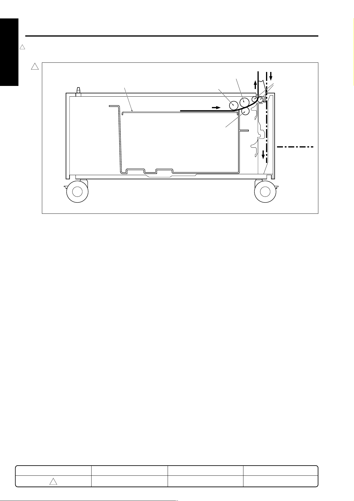
DB-409/410
1
CENTER CROSS SECTION
1 OUTLINE
2 UNIT EXPLANATION
3 DIS./ASSEMBLY
1
Double feed prevention roller/upper
Tray
Feed roller
Double feed prevention
roller/lower
Conveyance
roller
Paper feed path
for the reverse
side copy
:
REVISED EDITION
1
DATE
May 2000
1-2
PA GE
1-2
METHOD
REPLACEMENT
Page 9

DRIVE SYSTEM DIAGRAM
DB-409/410
1
Conveyance roller
Double feed prevention roller/upper
1st Paper feed SD (SD101)
1 OUTLINE
2 UNIT EXPLANATION
Paper feed motor (M100)
3 DIS./ASSEMBLY
REVISED EDITION
1
DATE
May 2000
1-3
PA GE
1-3
METHOD
REPLACEMENT
Page 10

1 OUTLINE
2 UNIT EXPLANATION
3 DIS./ASSEMBLY
Blank page
Page 11

2
UNIT EXPLANATION
1 OUTLINE
2 UNIT EXPLANATION
3 DIS./ASSEMBLY
Page 12

1 OUTLINE
2 UNIT EXPLANATION
3 DIS./ASSEMBLY
Blank page
Page 13

PAPER FEED SECTION
DB-409/410
[1] Composition
1
Rear edge stopper
Paper lift-up plate
[2] Mechanisms
Mechanism Method
Paper feed Paper feed roller
Paper lift-up * Paper lift-up plate
1
Double feed Torque limiter
prevention
Tray loading Front loading
1st paper feed Paper feed SD
Feed roller
Jam processing Release of pressure on
double feed prevention roller
No paper detect Photosensor
Paper size detect Size setting unit
1
Paper conveyance Roller conveyance
Conveyance drive Gears
Side guide
Size setting unit
Double feed prevention
roller/lower
Paper feed door
* Paper lift-up
The paper tray (LCT) is suspended on 4 up/down
drive wires (wires A, B, C, and D). When paper is
supplied to the paper tray, the tray falls under the
weight of the paper itself, but through the tension
of the drive assist spring, balance with the weight
of the paper is maintained.
When the paper tray (LCT) is loaded, the motor
1
rotates, causing the wire to be wound around the
drive pulley. As a result, the tray rises.
When the paper tray is withdrawn from the suspension base, the coupling with the drive is disconnected, and the tray falls to the position in
which the balance between the weight of the paper
and the drive-assist spring is maintained.
1
Wire A
Wire B
Wire D
Feed roller
Wire C
Double feed
prevention
roller/upper
Detection
wire
1 OUTLINE
2 UNIT EXPLANATION
3 DIS./ASSEMBLY
Tray motor
(M101)
REVISED EDITION
1
DATE
May 2000
2-1
Drive assist
spring
PA GE
2-1
Drive pulleys
Assist wire
METHOD
REPLACEMENT
Page 14

DB-409/410
1 OUTLINE
[3] Paper feed and no paper detection
control
2
2 UNIT EXPLANATION
24VDC
24VDC
PGND
PGND
5VDC
SGND
M100 CONT
SD101 CONT
PS103
PS109
DB SELECT1
DB SELECT0
24VDC
PGND
M100 CONT
24VDC
24VDC
P.GND
M100 LD
M100 CLK
M100 CONT
5VDC
S.GND
24VDC
SD101 DRIVE
EM
M100
DB-409
M100
DB-410
SD101
2. Signals
2
a. Input signals
(1) PS103 (PS103 → LCTDB)
Tray paper/no paper detection signal
[H]: no paper
[L] : with paper
(2) PS109 (PS109 → LCTDB)
Paper level in tray detection signal
Turns on with [L], sends main body that little paper is left.
(3) SD101 CONT (MAIN BODY → LCTDB)
SD101 ON/OFF control signal from main body
[H]: OFF
SGND
PS103 SIG
5VDC
SGND
PS109 SIG
MAIN BODY
LCTDB
5VDC
3 DIS./ASSEMBLY
Paper feed is carried out by transmitting the drive of the M100
(DB paper feed motor) to the paper feed roller and to the
feed roller. When feed starts, SD101 (1st. paper feed SD)
raises and lowers the feed roller and contacts the paper.
Drive of the M100, SD101 is carried out by LCTDB (LCT
drive board) and controlled by the main body.
No paper detection is carried out with PS103 (No paper
detect PS) and controlled by the main body via the LCTDB.
A related signal is the PS109 (Paper level detect PS2)
which sent the remaining paper level to the main body.
1. Operation
a. Paper feed operation timing
(1) 1st. sheet start
A specified time after start button is turned ON
(2) 2nd. sheet start
A specified time after 1st. sheet SD101 is turned ON
(3) OFF timing
A specified time after SD101 is turned ON
PS103
PS109
[L] : ON
b. Output signals
(1) M100 CONT (LCTDB → M100)
M100 drive control signal
[H]: M100 OFF
[L]: M100 ON
(2) M100 CLK (LCTDB → M100)
M100 rotation control board clock signal
(3) SD101 (LCTDB → SD101)
SD101 drive control signal
[H]: OFF
[L] : ON
(4) PS103 (LCTDB → MAIN BODY)
Paper/no paper detection signal sent to main body
(5) DB SELECT (LCTDB → MAIN BODY)
DB type identification signals that is sent to the main body
Signal
DB
DB-409/410
Not connected
Undefined
DB-SELECT 1
L
H
L
DB-SELECT 0
H
H
L
b. No paper detection
2
If paper in the tray is used up, PS103 goes OFF and
no paper detection signal is sent to the main body via
the LCTDB.
REVISED EDITION
2
DATE
Feb. 2001
2-2
PA GE
2-2
METHOD
REPLACEMENT
Page 15

DB-409/410
[4] Tray up and down control
24VDC
24VDC
PGND
PGND
5VDC
SGND
M101 CONT
PS101
PS102
MAIN BODY LCTDB
1. Operation
1
When the paper feed tray of each level is set, PS101
(Tray detect PS) detects the tray, M101 (Tray motor)
turns ON and lifts the base plate in the tray. When the
tray is lifted, PS102 (Paper level detect PS1) detects
the paper upper limit and turns on, then M101 turns
off and the raising of the tray is completed.
The down operation of the trays is performed mechanically.
M101 DRIVE
24VDC
SGND
PS101
5VDC
SGND
PS102
5VDC
M101
PS101
PS102
2. Signals
a. Input signals
(1) PS101 (PS101 → LCTDB)
Tray detect signal
By turning with [L] showing, M101 raises the paper in
the upper tray.
(2) PS102 (PS102 → LCTDB)
Upper tray upper limit detection signal
1
When the upper tray paper is lifted and arrives at the
upper limit position, the signal becomes [H] and
M101 is turned off.
(3) M101 CONT (MAIN BODY → LCTDB)
M101 ON/OFF control signal from main body
b. Output signals
(1) M101 DRIVE (LCTDB → M101)
M101 drive control signal
[L]: M101 ON
[H]: M101 OFF
(2) PS101 (LCTDB → MAIN BODY)
Tray detection signal sent to main body
1 OUTLINE
2 UNIT EXPLANATION
3 DIS./ASSEMBLY
(3) PS102 (LCTDB → MAIN BODY)
Paper upper limit detect signal sent to main body
REVISED EDITION
1
DATE
May 2000
2-3
PA GE
2-3
METHOD
REPLACEMENT
Page 16

DB-409/410
1 OUTLINE
[5] Paper size detection control
SIZE SELECT
LCTDB
SIZE D
SIZE C
SIZE B
SIZE A
2 UNIT EXPLANATION
MAIN BODY
24VDC
24VDC
PGND
PGND
5VDC
SGND
SIZE D
SIZE C
SIZE B
SIZE A
Tray paper size is detected in the main body by a signal
sent from SDB (size detection board) via the LCTDB (LCT
drive board).
1. Operation
a. Tray paper size detection
3 DIS./ASSEMBLY
Paper size for either tray is set by SW1 above SDB
and the LCTDB detects the switch signal corresponding to the position of SW1.
SW1
SDB
2. Signals
a. Input signal
(1) SIZE A - D (SDB → LCTDB)
Tray paper size detect signal
b. Output signal
(1) SIZE A - D (LCTDB → MAIN BODY)
Paper size detection signal sent to main body
The relation between switch signal and paper size is
as follows.
Paper size
Switch signal
(Label display
order)
SIZE A SIZE B SIZE C SIZE D
8.5 x 11R
A4
A4R
8.5 x 11
8.5 x 11R
B5R
B5
A4
A4R
8.5 x 11
2-4
Page 17

DB-409/410
[6] Control of paper-level detection
SGND
5VDC
NAIN BODY
After the trays have been set in the machine, paper level is
detected by PS101 (tray detect PS) and PS109 (paper
level detect PS2).
As the paper level in tray runs low, the actuator at the rear
part of the tray gradually rotates as illustrated below. The
remaining paper level is detected based on the ON/OFF
states of PS101 and PS109.
1
Direction of rotation when the
paper lifting plate is rising.
SGND
PS101
5VDC
SGND
PS109
5VDC
LCTDB
Viewing from the rear
Actuator
PS101
PS109
1 OUTLINE
2 UNIT EXPLANATION
3 DIS./ASSEMBLY
Paper level detect
sensor 2 (PS109)
Tray detect
sensor (PS101)
1. Operation
a. Detection of paper level in tray
The following shows the relation between the paper
level and the number of slit detections by the sensor
(PS101 or PS109).
Paper level PS101 PS109
Full
Medium
Low
REVISED EDITION
1
DATE
May 2000
2-5
PA GE
2-5
METHOD
REPLACEMENT
Page 18

1 OUTLINE
2 UNIT EXPLANATION
3 DIS./ASSEMBLY
Blank page
Page 19

3
DISASSEMBLY/ASSEMBLY
1 OUTLINE
2 UNIT EXPLANATION
3 DIS./ASSEMBLY
Page 20

1 OUTLINE
2 UNIT EXPLANATION
3 DIS./ASSEMBLY
This section explains how to disassemble and reassemble the
machine.
Observe the following precautions when performing disassembly
and assembly work.
1. Be sure to unplug the power cord before working on the
machine.
2. Perform all reassembly work by reversing the order in which the
component was disassembled, unless otherwise specified.
3. Do not lose small parts (screws, etc.) or insert them in the
wrong place.
4. Install all parts completely before operating the machine.
5. Do not loosen the screws indicated as disallowed for removal.
Page 21

DISASSEMBLY/ASSEMBLY
Caution: Make sure the power plug is taken
1
out of the socket.
[1] Removing and reinstalling the
paper feed tray
(1) Pull out the paper tray and take out the 4 set
screws and remove the tray front cover.
Set screws
DB-409/410
[2] Removing and reinstalling the
paper feed unit
(1) Remove the tray cover and the paper tray.
(2) Open the paper feed door, remove the three set
1
screws, then remove the size setting unit.
1
1 OUTLINE
Tray front cover
(2) Remove the 5 set screws from the guide rails and
remove paper tray from guide rails.
Paper tray
Set screws
Set screws
Guide rail
Set screws
Tray cover
Size setting
unit
(3) Remove the 3 set screws and remove the cover.
Set screws
(4) Remove the paper feed unit connector.
Set screws
Cover
Paper feed door
2 UNIT EXPLANATION
3 DIS./ASSEMBLY
(3) Install by reversing the removal procedure.
REVISED EDITION
1
DATE
May 2000
3-1
PA GE
3-1
METHOD
REPLACEMENT
Page 22

DB-409/410
(5) Remove the set screw indicated by the arrow
1 OUTLINE
2 UNIT EXPLANATION
3 DIS./ASSEMBLY
marking, and remove the paper-feed unit by pulling
it forward.
Set screw
Paper feed unit
(6) Install by reversing the removal procedure.
Caution 1: Immediately after installing the paper
feed unit, as the swing gear and the
paper feed solenoid are not in the correct
position, it sometimes happens that
paper is not fed. For this reason, always
make a copy to confirm that operation is
normal.
Caution 2: Install so that the swing gear shaft enters
the paper feed roller unit.
[3] Replacing the feed roller rubber and
double feed prevention rubber/upper
(1) Remove the paper feed unit.
(2) Remove the fixing rings and bearings.
(3) While withdrawing the paper feed shaft, remove the
double feed prevention roller/upper from the paper
feed roller unit.
Double feed prevention roller/upper
Feed shaft
Paper feed roller unit
Stopper rings
(4) Removing the fixing ring and remove the feed roller
by withdrawing the guide shaft in the direction
shown by the arrow.
(5) Remove the feed rubber form the feed roller.
(6) Remove the feed shaft and then remove the double
2
feed prevention roller/upper.
(7) Remove the double feed prevention rubber/upper
from the double feed prevention roller/upper.
REVISED EDITION
2
DATE
Feb. 2001
2
Paint mark
Feed rubber
Feed roller
Fixing ring
(8) Install by reversing the removal procedure.
Caution: Pay attention to the direction in which you install
each roller rubber. Install so that the swing-gear
shaft enters the paper feed roller unit.
3-2
PA GE
3-2
Guide shaft
Feed shaft
Double feed
prevention
roller/upper
Double feed
prevention
rubber/upper
METHOD
REPLACEMENT
Page 23

DB-409/410
[4] Replacing the double feed
prevention rubber/lower
(1) Remove the paper feed unit.
(2) Remove the set screw.
(3) Pushing the knobs on either side of the double feed
prevention unit, then remove by drawing it forward.
1
Knobs
(4) While pushing the projection of the lever click shaft,
withdraw it and remove the double feed prevention
roller.
Double feed prevention unit
Set screw
1 OUTLINE
2 UNIT EXPLANATION
3 DIS./ASSEMBLY
Paint mark
Double feed
prevention
rubber/lower
Double feed
prevention roller
Lever click shaft
(5) Remove the double feed prevention rubber/lower
from the double feed prevention roller.
(6) Install by reversing the removal procedure.
Caution: Pay attention to the direction in which you
install each roller rubber.
When installing the double-feed prevention
unit into the main body, align the unit with
the center of the marking stamped on the
main-body plate.
REVISED EDITION
1
DATE
May 2000
3-3
PA GE
3-3
METHOD
REPLACEMENT
Page 24

DB-409/410
1 OUTLINE
[5] Replacing the wires
Caution 1: After finishing wire replacement or
rewiring, raise and lower the tray by
hand to confirm that it rises and lowers
smoothly.
Caution 2: Do not cross wires or run them one on
top of another.
Caution 3: After installing wires, adjust the tray’s
tilt.
1
2 UNIT EXPLANATION
<Removing the wires>
Wire lengths
Wire A: 518.6±0.4mm
Wire B: 293.6±0.4mm
Wire C: 317.5±0.4mm
Wire D: 423.0±0.4mm
Assist wire: 245.2±0.5mm
Detection wire: 394.8±0.4mm
2. Remove assist wire from drive assist spring.
Tension fitting
Drive assist spring
Wire A
3. Rotating the drive assist reel counter clockwise, remove
the detection wire from the reel.
Wire D
Wire C
3.
Drive assist reel
3 DIS./ASSEMBLY
Wire B
Detection wire
2.
Set screw
E-ring
Assist wire
Wire
protection
cover
Wire A
Assist wire
Drive pulley
(front)
Assist wire
1. 1.
Set screw
Wire B
4. 5.
Wire C
Drive pulley (rear)
Detection
wire
Wire D
Detection wire
Wire
protection
cover
E-ring
1. Remove front and rear wire
protection covers.
4. Detaching the E-ring, remove
the drive pulley (front).
5. Detaching the E-ring, slide the
drive pulley (rear) forward.
6. Remove wire.
REVISED EDITION
1
DATE
May 2000
3-4
PA GE
3-4
METHOD
REPLACEMENT
Page 25

DB-409/410
1
<Stringing wires>
7. Attach the assist wire to the
drive assist spring. Turn the
tension fitting to apply
tension, and tighten the
screw.
7.
Drive assist spring
Tension fitting
Assist wire
1. Pass wires A, B, C, and D through tray.
2. Pass wires A and B along pulley groove
and pass over the adjustment material.
3. Pass wires C and D along pulley groove.
Wire A
2.
1.
Wire B
Wire C
3.
Wire D
8. Raise the paper lift plate. With the
wire tip pointing upward, wind
wires C and D around the drive
pulley 3 times. Then wind the
detection wire 1 time around to the
left (counterclockwise).
8.
9.
Drive assist reel
Detection
wire
1 OUTLINE
2 UNIT EXPLANATION
3 DIS./ASSEMBLY
Wire
protection
cover
Set screw
5.
Drive pulley (front)
E-ring
Assist wire
2
5. Having inserted assist wire and wires A and B into
the drive spindle, push the drive pulley on and fasten
the E-ring.
6. Wind the assist wire 5 times around the drive pulley
in a rightward direction.
Assist wire
Wire B
5 times around in a
rightward direction
10.
6.
11.
Wire
protection
cover
Set screw
4.
Wire C
4. Having inserted detection wire and
wires C and D into the drive spindle,
push the drive pulley on and fasten with
the E-ring.
11.Install the (rear) wire protection cover.10.Install the (front) wire protection cover.
Wire DWire A
Detection wire
Drive pulley
(rear)
E-ring
2
9. Rotate the detection
wheel approximately 1 turn counterclockwise, so that
the detection wire
winds 1 time around
the reel (starting
from the top).
REVISED EDITION
1
DATE
May 2000
3-5
PA GE
3-5
METHOD
REPLACEMENT
Page 26

1 OUTLINE
2 UNIT EXPLANATION
3 DIS./ASSEMBLY
Blank page
 Loading...