

Page 1

FS-107
SERVICE HANDBOOK
2001.02
Ver. 3.0
KONICA CORPORATION
TECHNOLOGY SUPPORT CENTER
TOKYO JAPAN
Page 2

KONICA CORPORATION
COPYRIGHT ©2001
CN26NF1780
Page 3

CONTENTS
CONTENTS
SAFETY AND IMPORTANT WARNING ITEMS ...........
Refer to the 7020/25/30/35 service handbook on page C-1
1. OUTLINE
FS-107 PRODUCT SPECIFICATIONS ..................1-1
[1] Type ........................................................ 1-1
[2] Functions ................................................ 1-1
[3] Stapler kit ................................................ 1-2
[4] Machine data .......................................... 1-2
[5] Maintenance ........................................... 1-2
[6] Machine environment ............................. 1-2
CENTER CROSS SECTION ..................................1-3
DRIVE SYSTEM DIAGRAM ................................... 1-4
[1] Paper conveyance drive ......................... 1-4
[2] Stapler unit drive ..................................... 1-5
PAPER CONVEYANCE PATH .............................. 1-6
[1] Straight mode ......................................... 1-6
[2] Offset mode/staple mode ....................... 1-7
2. UNIT EXPLANATION
EXTERNAL SECTION ........................................... 2-1
[1] Composition ............................................ 2-1
CONVEYANCE SECTION ..................................... 2-2
[1] Composition ............................................ 2-2
[2] Mechanisms ........................................... 2-2
[3] Conveyance control ................................ 2-3
[4] Tray up/down control .............................. 2-5
PAPER EXIT/STAPLER UNIT ............................... 2-7
[1] Composition ............................................ 2-7
[2] Mechanisms ........................................... 2-7
[3] Paper alignment control .......................... 2-9
[4] Paper exit control .................................. 2-10
[5] Paper stack control ............................... 2-11
[6] Stapler control ...................................... 2-12
[7] Staple control ........................................ 2-13
OTHER CONTROLS ............................................2-15
[1] Movement with power on ...................... 2-15
[2] Opening and closing motion of
the front door ........................................ 2-15
1 OUTLINE
2 UNIT EXPLANATION
3 DIS./ASSEMBLY
3. DISASSEMBLY/ASSEMBLY
DISASSEMBLY/ASSEMBLY .................................. 3-1
[1] Removing and reinstalling of the finisher
unit .......................................................... 3-1
[2] Removing and installing of the tray ........ 3-1
[3] Replacing the paper exit roller/A ............ 3-2
[4] Removing and installing of the up/down
wire ......................................................... 3-4
[5] Replacing the stapler cartridge ............... 3-5
[6] Removing and installing
the stapler unit........................................ 3-6
Page 4

1
OUTLINE
1 OUTLINE
2 UNIT EXPLANATION
3 DIS./ASSEMBLY
Page 5
FS-107 PRODUCT SPECIFICATIONS
FS-107
[1] Type
Type: Built-in type compact finisher
(multiple trays type)
Option: Finisher tray [FT-107]
(Up to two trays can be
installed)
[2] Functions
Kinds of paper: Same as the main body
Modes: Normal exit mode (straight)
Offset mode (shift)
Staple mode
Paper size
2
Straight paper exit: A3, B4, A4, A4R, B5, B5R,
A5R, B6R, F4, 11 x 17, 8.5 x
14, 8.5 x 11, 8.5 x 11R, 5.5 x
8.5R
Offset: A3, B4, A4, A4R, B5, B5R,
F4, 11 x 17, 8.5 x 14, 8.5 x 11,
8.5 x 11R
1 position staple: A3, B4, A4, A4R, B5, B5R, A5R,
One point F4, 11 x 17, 8.5 x 14, 8.5 x 11,
8.5 x 11R, 5.5 x 8.5R
2 position staple: A3, B4, A4, A4R, B5, B5R, A5R,
Two points F4, 11 x 17, 8.5 x 14, 8.5 x 11,
8.5 x 11R, 5.5 x 8.5R
Maximum
Paper capacity: 2 trays:100 +1000 = 1,100
sheets
3 trays: 100 + 100 + 600 =
800 sheets
4 trays: 100 x 4 = 400 sheets
Copy
Paper weight: 50 to 200g/m
Stack capacity: (80g/m
With 2 standard trays
2
papers
2
high-quality paper)
Note 2: The number of stacked sheets in staple
mode must not exceed the stack sheet
capacity for non-staple mode.
Note 3: Small size: B6R, A5R, 5.5x8.5R
Medium size: Everything other than
small size, large size,
special paper.
Large size: A3, B4, F4, 8.5x14,
11x17
Special paper: Thin paper (60g/m
less), thick paper (over
128g/m
masters, OHP, etc.
Note 4: The stacking capacity of the option
conforms to the stacking capacity of tray
1.
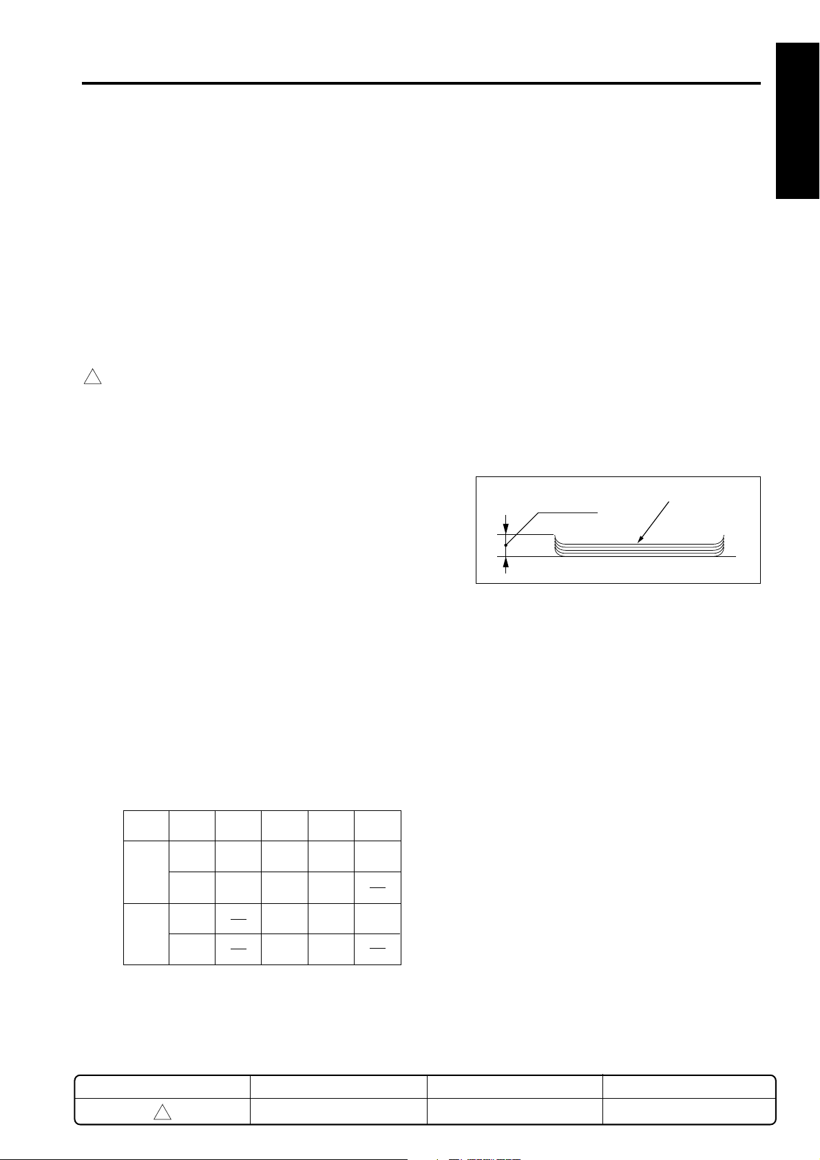
Paper curling: 10mm max
Curl
Amount of sort
off-setting: 30mm
2
), blueprint
Five copy sheets
2
1 OUTLINE
or
2 UNIT EXPLANATION
3 DIS./ASSEMBLY
Small
Non-
Tray 1
Tray 2
Note 1: The above figures apply only to if
REVISED EDITION
staple
Staple
Nonstaple
Staple
stacked paper is all of the same size.
2
sheets
Medium
size
100
sheets
10
sets
1000
sheets
size
100
10
sets
50
sets
Large
size
100
sheets
10
sets
300
sheets
20
sets
DATE
Feb. 2001
Special
media
sheets
sheets
10
50
1-1
PA GE
1-1
METHOD
REPLACEMENT
Page 6
FS-107
1
[3] Stapler kit
1 OUTLINE
Staple ability Maximum 50 sheets (with
Stapler capacity: 5,000 staples/cartridge
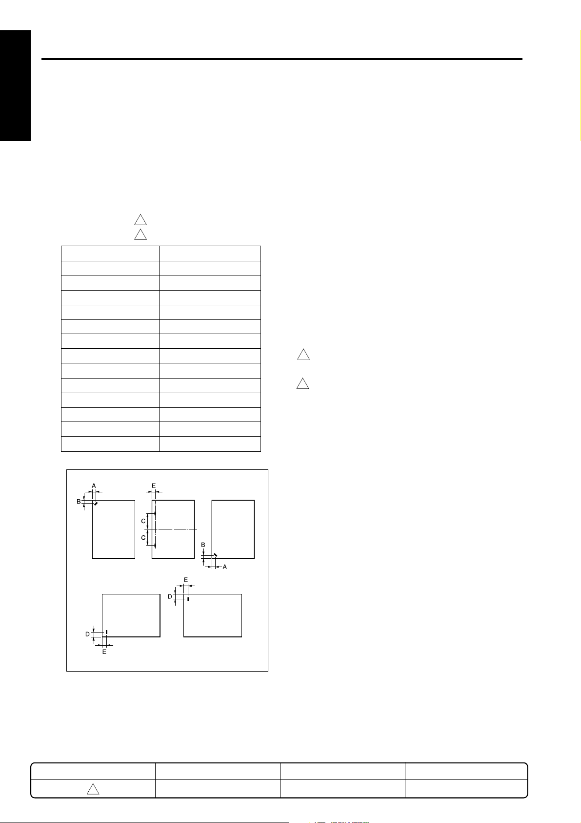
Staple position: A = 8.6mm ± 3mm
2 UNIT EXPLANATION
3 DIS./ASSEMBLY
Paper Size
A3/A4
B4/B5
A4R/A5
B5R
A5R
F4 (8 x 13)
F4 (8.125 x 13)
F4 (8.25 x 13)
F4 (8.5 x 13)
11 x 17/8.5 x 11
8.5 x 14/8.5 x 11R
5.5 x 8.5
5.5 x 8.5R
2
80g/m
ness less than 5mm)
B = 8.6mm ± 3mm
C = refer to following table
D = 10.5mm ± 3mm
1
E = 8.0mm ± 3mm
1
paper, paper thick-
C (mm)
60±4
53±4
90±4
80±4
63±4
90±4
91.5±4
93±4
95±4
52±4
95±4
95±4
60±4
[4] Machine data
Power source: DC24V/5V (supplied from the
main body)
Maximum power
Consumption: Max.70VA
Weight: 13kg
External
dimensions: Length 782mm
Depth 502mm
Height 392mm
[5] Maintenance
Maintenance: Same as the main unit
Machine life: Same as the main unit
[6] Machine environment
Temperature: 10 to 30˚C
Humidity: 20 to 80%RH
1
Note: Specifications are subject to change without
notice.
REVISED EDITION
1
DATE
May 2000
1-2
PA GE
1-2
METHOD
REPLACEMENT
Page 7

1
CENTER CROSS SECTION
FS-107
1 OUTLINE
Tray 2
Tray 1
Exit rolle/A
Conveyance roller
2 UNIT EXPLANATION
Conveyance rollers
Stapler unit
3 DIS./ASSEMBLY
Conveyance belt
REVISED EDITION
1
DATE
May 2000
1-3
PA GE
1-3
METHOD
REPLACEMENT
Page 8
FS-107
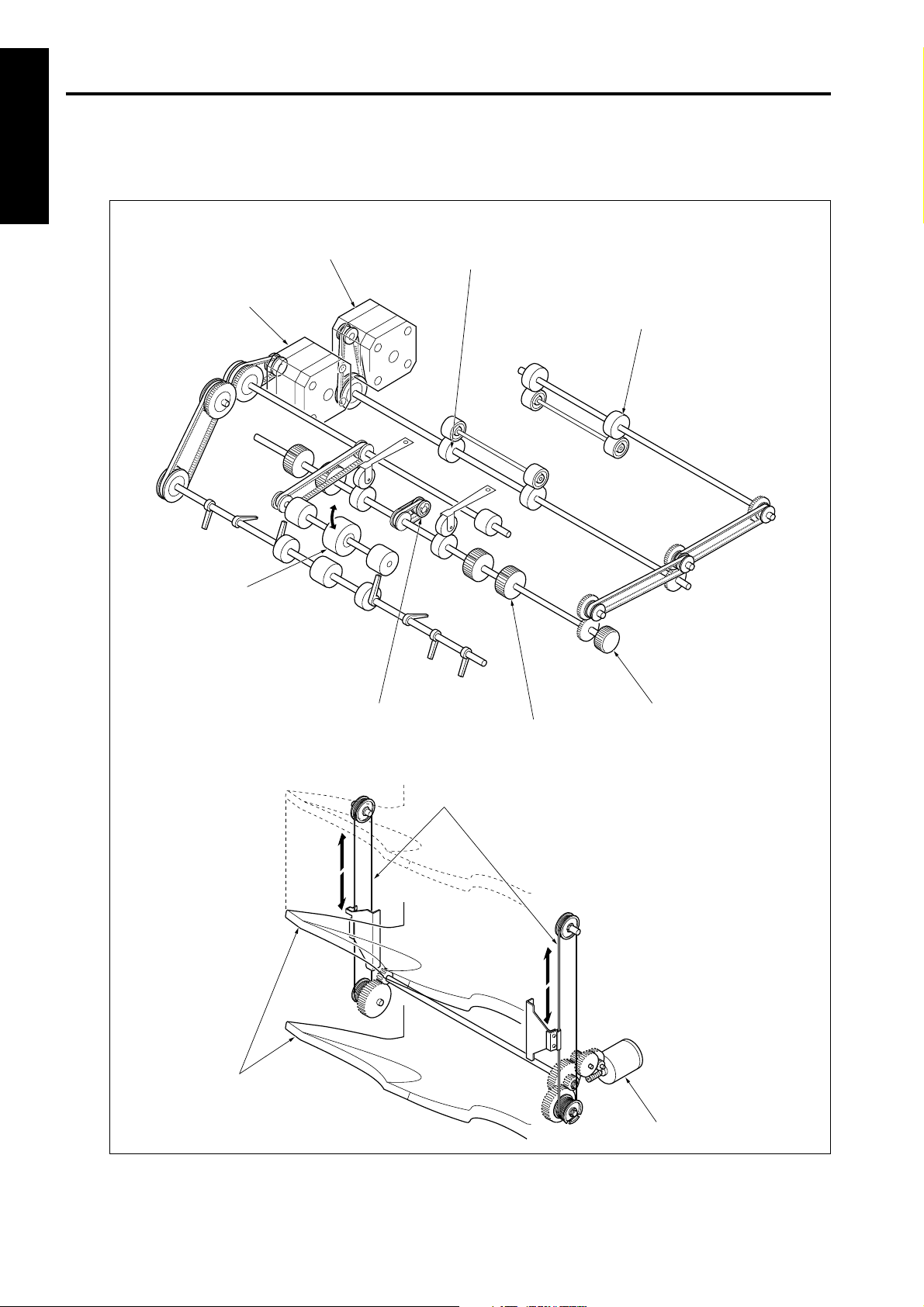
DRIVE SYSTEM DIAGRAM
1 OUTLINE
[1] Paper conveyance drive
Paper conveyance
motor (M701)
Paper exit motor (M702)
2 UNIT EXPLANATION
Conveyance roller
Conveyance roller
3 DIS./ASSEMBLY
Exit roller A
Conveyance belt
Paper jam release knob
Conveyance roller
Tray up/down wires
Trays
Tray up/down motor (M706)
1-4
Page 9
FS-107
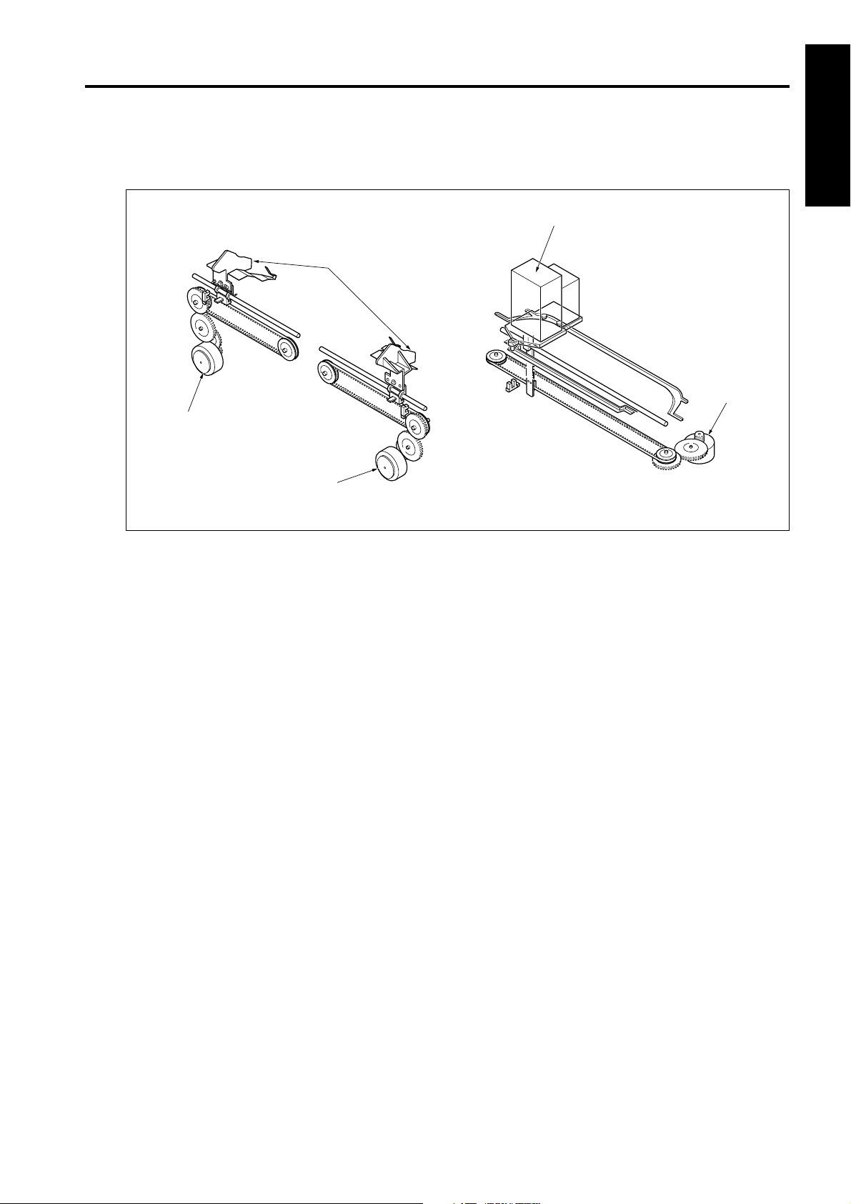
[2] Stapler unit drive
Alignment motor
(rear) (M703)
Alignment motor
(front) (M704)
Alignment plates
Stapler unit
Stapler shift
motor (M705)
1 OUTLINE
2 UNIT EXPLANATION
3 DIS./ASSEMBLY
1-5
Page 10
FS-107
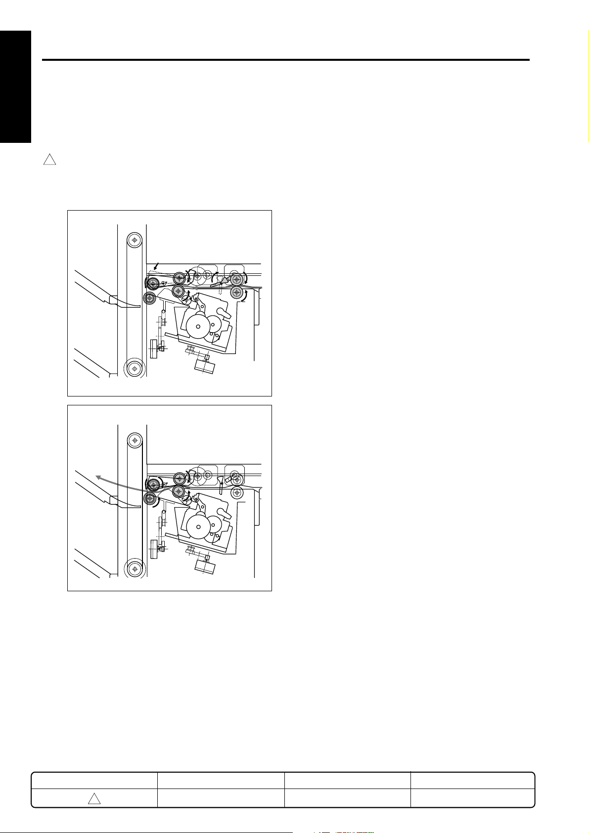
PAPER CONVEYANCE PATH
In the finisher, two different paper conveyance paths are
1 OUTLINE
used, changing by the mode selected.
[1] Straight mode
1
In this mode, paper conveyed to the finisher is exited
straight into the tray. (For small size paper, the
operation of [2] Offset Mode/Stapling Mode takes
place, even in the straight paper exit mode.)
2 UNIT EXPLANATION
3 DIS./ASSEMBLY
REVISED EDITION
1
DATE
May 2000
1-6
PA GE
1-6
METHOD
REPLACEMENT
Page 11

FS-107
[2] Offset mode/staple mode
In the offset mode or staple mode, paper conveyed
to the finisher is stacked once by the reverse rotation
of the exit roller. In the offset mode, this stacked
paper is offset by the paper alignment plates. In the
staple mode, the paper is stapled. When the respective
process is finished, the paper is exited to the tray by the
exit roller.
1
Paper exit roller
Alignment plate
1 OUTLINE
2 UNIT EXPLANATION
3 DIS./ASSEMBLY
REVISED EDITION
1
DATE
May 2000
1-7
PA GE
1-7
METHOD
REPLACEMENT
Page 12

2
1
1 OUTLINE
2 UNIT EXPLANATION
UNIT EXPLANATION
3 DIS./ASSEMBLY
Page 13

EXTERNAL SECTION
FS-107
[1] Composition
1
Front door
Conveyance door
Paper conveyance cover
Stapler unit
Tray 1
1 OUTLINE
Optional tray 1
[FT-107]
2 UNIT EXPLANATION
Optional tray 2
[FT-107]
Tray 2
3 DIS./ASSEMBLY
REVISED EDITION
1
DATE
May 2000
2-1
PA GE
2-1
METHOD
REPLACEMENT
Page 14

FS-107
1
CONVEYANCE SECTION
1 OUTLINE
[1] Composition
Tray 1
Paper conveyance motor (M701)
2 UNIT EXPLANATION
Tray up/down wire
Tray 2
3 DIS./ASSEMBLY
[2] Mechanisms
Mechanism System
Paper Conveyance Conveyance rollers
Tray Up/Down *1 Wire drive
Tray Up/Down Accident Shutter
Prevention *2
Conveyance rollers
Conveyance roller
Tray up/down motor (M706)
Tray up/down wires
*1 Tray up/down
The paper exit gate position is fixed; switching
between trays is accomplished by changing the
tray position up/down mechanism.
Tray up and down is done by the tray up/down
motor (M706), which the tray up/down wires to
drive the tray up or down.
REVISED EDITION
DATE
Trays
PA GE
Tray up/down
motor (M706)
METHOD
2-2
1
May 2000
2-2
REPLACEMENT
Page 15

FS-107
*2 Prevention of tray up/down accident
To prevent the accident insertion of the hand into
the paper exit gate during tray motion up or down,
the paper exit gate is equipped with a shutter. The
shutter is driven by the reverse motion of the paper
pressure motor (M707), closing the paper exit gate
when the tray is in motion.
Shutter
Paper pressure motor (M707)
[3] Conveyance control
5VDC
PS3
SGND
24VDC
24VDC
24VDC
5VDC
5VDC
SGND
SGND
PGND
PGND
PGND
SGND
SGND
M ACK
SGND
S REQ
M RXD
SGND
S ACK
M REQ
SGND
M TXD
MAIN BODY
Conveyance is accomplished by the drive force of the
M701 (paper conveyance motor), which is transmitted to
the conveyance rollers. The M701 is linked with the main
body, so that rotation is set to low or high speed according
to the conveyance movement during copying.
The M701 is controlled by the FS CB (FS control board).
Related signals are provided by the PS702 (paper
entrance detect PS), PS717 (conveyance cover open/
close detect PS) and the MS701 (front door switch) and
PS3 (paper exit PS) of the main body.
PS3
M701 OUT A
M701 OUT A
M701 OUT B
M701 OUT B
FS CB
24VDC
24VDC
5VDC
PS702
SGND
5VDC
PS717
SGND
24VDC
MS701
M701
PS702
PS717
MS701
1 OUTLINE
2 UNIT EXPLANATION
3 DIS./ASSEMBLY
REVISED EDITION
1
DATE
May 2000
1. Operation
1
2-3
As paper passes by the PS3 of the main body, the
M701 conveys the paper at a low speed in relation
with the paper exit velocity of the main body. When
the end of the paper passes through the PS3, the
M701 then conveys the paper at high speed. The
M701 again changes to low speed after the specified
period of time when the end of the paper passes
through the PS702, ready to convey the next sheet of
paper.
PA GE
2-3
METHOD
REPLACEMENT
Page 16

FS-107
2. Signals
1 OUTLINE
a. Input signals
(1) PS3 (PS3 → PRDB)
When the main body paper exit section detection
signal detects paper, [H] is output.
(2) PS702 (PS702 → FS CB)
Conveyance section paper entrance detection signal
[L]: No paper is present
[H]: Paper is present
(3) PS717 (PS717 → FS CB)
2 UNIT EXPLANATION
Conveyance plate opening/closing detection signal
[L]: Conveyance plate open
[H]: Conveyance plate closed
(4) MS701 (MS701 → FS CB)
Power supply line for each load
When the finisher front door is closed, 24VDC is
supplied to each load.
3 DIS./ASSEMBLY
(5) S ACK (MAIN BODY → FS CB)
Transmission of OK signal from the main body to the
finisher.
b. Output signals
(1) M701 OUTA, M701 OUTA, M701 OUTB, M701
OUT B (FS CB → M701)
M701 drive control signal
24V
0V
(2) M ACK (FS CB → MAIN BODY)
Transmission of OK signal from the finisher to the
main body.
(3) S REQ (FS CB → MAIN BODY)
Transmission of request signal from the finisher to
the main body.
(4) M RXD (FS CB → MAIN BODY)
Serial data sign sending the movement condition of
the finisher to the main body CB.
(6) M TXD (MAIN BODY → FS CB)
Serial data sign sending the movement condition of
the main body to the finisher.
(7) M REQ (MAIN BODY → FS CB)
Transmission of request signal from the main body to
the finisher.
2-4
Page 17

FS-107
[4] Tray up/down control
24VDC
24VDC
24VDC
5VDC
5VDC
SGND
SGND
PGND
PGND
PGND
SGND
SGND
M ACK
SGND
S REQ
M RXD
SGND
S ACK
M REQ
SGND
M TXD
MAIN BODY
The paper exit position of the FS is fixed, the selected tray
is elevated or lowered to the paper exit position. Control of
the tray up/down is by the M706 (tray up/down motor)
which drives wires which is connected to and moves the
trays up and down.
The M706 is controlled by the FS CB (FS control board).
Related signals are provided by the PS703 (paper exit
detect PS), PS706 (tray lower limit detect PS), PS716
(tray count PS) and the MS702 (shutter switch).
M706 DRIVE 1
M706 DRIVE 2
5VDC
PS706
SGND
5VDC
PS703
SGND
5VDC
PS716
SGND
24VDC
MS702
FS CB
M706
PS706
PS703
PS716
MS702
1. Operations
a. Tray lower limit detection operation
With the power swich turnd ON, and the PS706 OFF,
the M706 is reversed and the tray is lowered until the
PS706 is turned ON.
b. Tray count operation
One or two optional trays can be installed.
If PS716 goes OFF after the lower limit of the tray has
1
been detected, the machine judges that no optional
trays are installed.
When PS716 is ON, optional tray 1 is in place; in this
condition the M706 rotates normally, raising the tray
one step up until PS716’s detection position where
motion is stopped. Whether PS716 is ON or OFF at
this point determines whether optional tray 2 is in
place or not.
The number of trays is counted by means of a series
1
of operations.
After the tray count, the default tray that was set in
the key operator mode is set in the exit position.
c. Tray movement operation
If the exit tray has been selected at the LCD, then
1
when copying starts M706 turns ON and moves the
selected tray so that it sets into the exit position.
The number of times PS703 switches ON and OFF
sets the selected tray into the paper exit position.
1 OUTLINE
2 UNIT EXPLANATION
3 DIS./ASSEMBLY
REVISED EDITION
1
DATE
May 2000
d. Shutter switch operation
While the tray is in motion, the shutter, which
prevents the fingers or foreign objects from entering
the paper exit gate, is closed, with MS702 in the ON
position supplying 24VDC to the various loads. While
the tray is being raised or lowered the shutter is
opened and MS702 is OFF, interrupting the flow of
electricity and halting the motion of the FS.
PAGE
2-5
2-5
METHOD
REPLACEMENT
Page 18

FS-107
2. Signals
1 OUTLINE
a. Input signals
(1) PS706 (PS706 → FS CB)
Tray lower limit detection signal
[L]: Not at lower limit
[H]: Lower limit
(2) PS703 (PS703 → FS CB)
Paper exit detection signal
[L]: Top face
2 UNIT EXPLANATION
[H]: Not at top face
(3) PS716 (PS716 → FS CB)
Tray installation detection signal
[L]: No tray
[H]: Tray in position
(4) PS702 (PS702 → FS CB)
The power supply line for each load.
3 DIS./ASSEMBLY
24VDC is supplied to each load when the shutter is
closed.
b. Output signal
(1) M706 DRIVE 1, 2 (FS CD → M706)
M706 drive control signal
The drive direction of the M706 is controlled by two
signals which change the direction of the electrical
current.
2-6
Page 19

PAPER EXIT/STAPLER UNIT
FS-107
[1] Composition
Trays
Exit roller/A
Alignment plates
Alignment motors
(M703, M704)
Stapler unit
Stapler shift motor (M705)
1 OUTLINE
2 UNIT EXPLANATION
3 DIS./ASSEMBLY
[2] Mechanisms
Mechanism System
Paper Alignment *1 Separate plates for front
and rear
Paper Exit *2 Exit roller/A
Paper Stacking *3 Exit roller/A
Conveyance belt
Stapler Unit Shift *4 Stapler shift motor
*1 Paper alignment
Paper conveyed to the paper exit gate by the conveyance roller is stacked by reverse rotation of the
paper exit roller/A. The stacked paper is aligned by
the alignment plates. Independently-driven alignment plates are set on both the front and rear
sides, allowing independent operation at the front
and rear during shift mode. The alignment plates
are driven by alignment motors M704 (front) and
M703 (rear).
Alignment plate (rear)
Alignment plate (front)
Alignment motor (rear)
(M703)
Alignment motor (front)
(M704)
2-7
Page 20

FS-107
1 OUTLINE
1
2 UNIT EXPLANATION
3 DIS./ASSEMBLY
*2 Paper exit
In the straight mode, paper conveyed to the paper
exit gate by the conveyance rollers is conveyed to
the tray through paper pressure being applied to
paper exit roller/A by the paper pressure motor
(M707) and the roller being made to run forward.
(Does not apply to small paper sizes.)
In offset mode or staple mode, when the stacked
paper is conveyed, paper pressure being applied
to paper exit roller/A by the paper pressure motor
(M707) and the roller being made to run forward,
all the stacked paper is conveyed into the tray.
Straight mode
Paper exit roller/A
Offset mode/staple mode
*3 Paper stack
In the offset mode or staple mode, paper conveyed to the paper exit gate by the conveyance
rollers is then conveyed to the stack position by
paper exit roller/A running in reverse direction.
The conveyed paper is sent to the stopper by the
friction of the conveyance belt and stacked.
*4 Stapler unit shift
The stapler unit is driven by the stapler shift motor;
1
the stapler unit is fixed on the staple base and
moved by a belt along a rail. Owing to the shape of
the rail, when the stapler unit is moved to either the
forward or rear positions, the unit rotates and it is
possible to staple slantwise.When the stapler is
set to staple in two locations, it moves to the first
location, puts in the first staple, then moves to the
second location to put in the second staple.
REVISED EDITION
1
DATE
May 2000
2-8
Stapler unit
Belt
PA GE
2-8
Rails
Stapler shift motor
(M705)
METHOD
REPLACEMENT
Page 21

FS-107
[3] Paper alignment control
24VDC
24VDC
M702 OUT A
M702 OUT A
M702 OUT B
M702 OUT B
24VDC
24VDC
M703 OUT A
M703 OUT A
M703 OUT B
M703 OUT B
M704 OUT A
M704 OUT A
M704 OUT B
M704 OUT B
FS CB
24VDC
24VDC
5VDC
PS702
SGND
5VDC
PS709
SGND
5VDC
PS710
SGND
MAIN BODY
24VDC
24VDC
24VDC
5VDC
5VDC
SGND
SGND
PGND
PGND
PGND
SGND
SGND
M ACK
SGND
S REQ
M RXD
SGND
S ACK
M REQ
SGND
M TXD
M702
M703
M704
PS702
PS709
PS710
1. Operations
a. Normal alignment operation
The front and rear alignment plates work in symmetry
to the front and rear based on the center of the
alignment section, alternately aligning and releasing.
To create this symmetrical movement the M703 and
M704 always rotate in opposite directions.
Every five sheets of the conveyed paper are aligned
and sent on to the paper exit section.
The timing of the M703 and M704 are set to the
starting point by the ON/OFF of the PS702 (paper
entrance detect PS).
b. Offset (shift alignment) operation
1
The sheets corresponding to odd sets of copies are fed
to the paper exit unit as soon as they have been aligned
normally. (up to 5 sheets are stacked and exited.)
During the alignment operation for even sets of
copies, M703 and M704 rotate in the same direction,
shifting the sheets forward from the center. The
aligned sheets are then sent to the paper exist
unit.(up to 5 sheets are stacked and exited.)
1 OUTLINE
2 UNIT EXPLANATION
3 DIS./ASSEMBLY
During sorting and stapling, paper exited by the
conveyance section is sent to the alignment section by the
M702 (paper exit motor) reverse direction, then aligned by
the alignment plates driven by the M703 (alignment motor,
(rear)) and the M704 (alignment motor, (front)).
The home position of the alignment plates is detected by
the PS709 (alignment plate detect PS (rear)) and the
PS710 (alignment plate detect PS (front)). The FS CB (FS
control board) controls the M702, M703 and M704. The
related signal are passed to the PS702 (paper entrance
detect PS).
c. Staple mode operation
In the staple mode, the M703 and M704 are released
after the stapling action is completed.
The ON/OFF timing of the M703 and M704 is set as
the M702 is turned from OFF to ON, and the PS702 is
turned OFF after the specified period of time.
REVISED EDITION
1
DATE
May 2000
2-9
PA GE
2-9
METHOD
REPLACEMENT
Page 22

FS-107
2. Signals
1 OUTLINE
a. Input signals
[4] Paper exit control
(1) PS709 (PS709 → FS CB)
Detection signal of the home position of the
alignment plate (rear)
[L]: Non-home position
[H]: Home position
(2) PS710 (PS710 → FS CB)
Detection signal of the home position of the
alignment plate (front)
2 UNIT EXPLANATION
[L]: Non-home position
[H]: Home position
b. Output signals
(1) M702 OUT A, M702 OUT A–, M702 OUT B,
M702 OUT B– (FS CB → M702)
Drive control signal for M702
3 DIS./ASSEMBLY
24V
0V
5VDC
MAIN BODY
PS3
SGND
24VDC
24VDC
24VDC
5VDC
5VDC
SGND
SGND
PGND
PGND
PGND
SGND
SGND
M ACK
SGND
S REQ
M RXD
SGND
S ACK
M REQ
SGND
M TXD
PS3
FS CB
24VDC
24VDC
M702 OUT A
M702 OUT A
M702 OUT B
M702 OUT B
M707 DRIVE 1
M707 DRIVE 2
M708 DRIVE 1
M708 DRIVE 2
5VDC
PS701
SGND
5VDC
PS702
SGND
5VDC
PS703
SGND
5VDC
PS707
SGND
M702
M707
M708
PS701
PS702
PS703
PS707
Papers that have already been aligned or stapled are
exited by the paper exit roller.
(2) M703 OUT A, M703 OUT A–, M703 OUT B,
M703 OUT B– (FS CB → M703)
Drive control signal for M703
24V
0V
(3) M704 OUT A, M704 OUT A–, M704 OUT B,
M704 OUT B– (FS CB → M704)
Drive control signal for M704
24V
0V
A mechanical clutch is connected to M702 (paper exit
motor). A mechanical clutch can convey the forward
direction driving power to the exit roller with certain
movement.
The M702 is responsible for speed control for connection
with the mechanical clutch, for sending the alignment
section at the reversal rotation, and also during the usual
paper exit.
The M702 is controlled by the FS CB (FS control board).
The related signals are M707 (paper pressure motor),
M708 (stapler motor), PS701 (paper pressure PS), PS702
(paper entrance detect PS), PS703 (paper exit detect PS),
and PS707 (no paper detect PS).
2-10
Page 23

FS-107
1. Operation
During paper exit, both upper and lower exit rollers
are compressed as a consequence of the operation
performed by M707, and that condition is detected by
the ON/OFF state of PS701.
a. Non-staple mode operation
The ON/OFF timing of M702 is such that it turns ON
during the OFF of PS3, and turns OFF during the
OFF of PS702.
After the paper exit tray goes up until PS703 turns
ON, M706 moves the tray up and down in order to
keep the ON state of PS703 during paper exit.
b. Staple mode operation
M702 turns ON a certain time after M708 finishes the
stapling operation and turns OFF.
The subsequent operations are the same as for the
non-staple operation.
2. Signals
a. Input signal
(1) PS701 (PS701 → FS CB)
Pressure detection signal of the exit paper compressing plate
[L]: Pressure
[H]: Release
[5] Paper stack control
24VDC
24VDC
24VDC
5VDC
5VDC
SGND
SGND
PGND
PGND
PGND
SGND
SGND
M ACK
SGND
S REQ
M RXD
SGND
S ACK
M REQ
SGND
M TXD
MAIN BODY
When the stack of the papers on the paper exit tray is full,
a message is put up on the LCD.
During the automatic switching mode of the tray, a
message is not put up on the LCD. The tray located 1 step
below is brought to the paper exit position by a vertical
movement of M706 (tray up/down motor).
The M706 is controlled by FS CB (FS control board).
The related signals are PS702 (paper entrance detect
PS), PS703 (paper exit detect PS), PS704 (tray full-stack
detect PS), PS706 (tray lower limit detect PS), and PS716
(tray count PS).
M706 DRIVE 1
M706 DRIVE 2
5VDC
PS702
SGND
5VDC
PS703
SGND
5VDC
PS704
SGND
5VDC
PS706
SGND
5VDC
PS716
SGND
FS CB
M706
PS702
PS703
PS704
PS706
PS716
1 OUTLINE
2 UNIT EXPLANATION
3 DIS./ASSEMBLY
b. Output signals
(1) M707 DRIVE 1,2 (FS CB → M707)
M707 drive control signal
The drive direction of the M707 is controlled by two
signals which change the direction of the electrical
current.
(2) M708 DRIVE 1,2 (FS CB → M708)
M708 drive control signal
The drive direction of the M708 is controlled by two
signals which change the direction of the electrical
current.
The automatic switching mode of the tray can be
controlled using the 25 modes of the main unit.
2-11
Page 24

FS-107
1. Operation
1 OUTLINE
a. Up/down operation
When the tip of the paper turns PS702 ON, the tray is
driven down by a certain amount. After the rear of the
paper turns PS702 OFF, M706 turns ON driving the
tray up until PS703 is turned ON.
b. Full-stack detection operation
When a tray other than tray 1 is selected and PS703
is turned ON when PS704 is ON, the paper-full
condition is detected. When tray 1 is selected and PS
2 UNIT EXPLANATION
703 is turned ON when PS706 is ON, the paper-full
condition is detected.
c. Automatic tray switching operation
When tray 1, optional tray 1, and optional tray 2 are
selected and the paper-full condition is detected,
M706 drives the tray up so that PS703 is turned OFF
and then ON again, and the immediately lower tray is
set at the paper exit position.
3 DIS./ASSEMBLY
When tray 2 is selected and the paper-full condition is
detected, M706 drives the tray down until PS716 is
turned ON, and then up until PS703 is turned ON, set
tray 1 at the paper exit position.
[6] Stapler control
24VDC
24VDC
24VDC
5VDC
5VDC
SGND
SGND
PGND
PGND
PGND
SGND
SGND
M ACK
SGND
S REQ
M RXD
SGND
S ACK
M REQ
SGND
M TXD
MAIN BODY
M705 (staple shift motor) performs staple displacement
control by moving the stapler unit up to the stapler
operation position.
The home position of the stapler unit is detected by PS708
(stapler unit HP detect PS).
M705 is controlled by FS CB (FS control board).
M705 OUT A
M705 OUT A
M705 OUT B
M705 OUT B
FS CB
24VDC
24VDC
5VDC
PS708
SGND
M705
PS708
2. Signal
a. Input signal
(1) PS704 (PS704 → FS CB)
Paper-full detection signal
Goes [H] when paper-full condition is detected.
1. Operation
The stapler unit is usually at the home position of the
finisher.
When receiving a command signal from the main
unit, M705 moves the stapler unit to the stapling
position according to paper size and starts the
stapling operation.
After finishing the copy, M705 moves the stapler unit
to its home position.
The M705 OFF timing is controlled by the number of
driving steps after PS708 is turned OFF.
2-12
Page 25

FS-107
1
2. Signal
a. Input signal
(1) PS708 (PS708 → FS CB)
Detection signal of the home position of the stapler
unit
[L]: Non-home position
[H]: Home Position
b. Output signal
(1) M705 OUT A, M705 OUT A–, M705 OUT B,
M705 OUT B– (FS CB → M705)
Drive control signal for M705
24V
0V
[7] Staple control
24VDC
24VDC
M705 OUT A
M705 OUT A
M705 OUT B
M705 OUT B
M707 DRIVE 1
M707 DRIVE 2
M708 DRIVE 1
M708 DRIVE 2
5VDC
PS701
SGND
5VDC
PS708
SGND
5VDC
PS712
SGND
5VDC
PS713
SGND
FS CB
MAIN BODY
24VDC
24VDC
24VDC
5VDC
5VDC
SGND
SGND
PGND
PGND
PGND
SGND
SGND
M ACK
SGND
S REQ
M RXD
SGND
S ACK
M REQ
SGND
M TXD
In staple mode, stapling is performed using the driving
force of the M708 (stapler motor).
M705
M707
M708
PS701
PS708
PS712
PS713
1 OUTLINE
2 UNIT EXPLANATION
3 DIS./ASSEMBLY
M708 is controlled by FS CB (FS control board).
The related signals are M705 (stapler shift motor), M707
(paper pressure motor), PS701 (paper pressure PS),
PS708 (stapler unit HP detect PS), PS712 (stapler HP
detect PS), PS713 (no-staple PS), and PS714 (stapler
ready PS).
The maximum number of sheets that can be stapled, and
the operation when stapling is not possible, can be chosen
in the 25 mode of the main body.
REVISED EDITION
DATE
PAGE
METHOD
2-13
1
May 2000
2-13
REPLACEMENT
Page 26

FS-107
1. Operation
1 OUTLINE
a. Stapler operation
After the aligning operation of the last paper, M707 is
turned ON and compresses the paper using the exit
rollers. Then, M708 is turned ON and stapling begins.
When PS701 is turned OFF, M707 is turned OFF,
PS712 is turned ON, and M708 is turned OFF.
For continuous stapling, M705 is not turned ON, and
the stapler unit waits for the next stapling at the same
position.
In the case of 2 stapling positions, the first staple is
2 UNIT EXPLANATION
executed and then M705 moves the stapler to the
specified position for the second staple. M708 then
turns ON and executes the second staple. At this
moment, if continuous stapling has been selected,
the stapler unit stops at the immediately previous
stapling position. When the first stapling operation of
the next paper is done, M705 moves the stapler unit
for the second stapling operation.
After the copy is finished, the stapler unit returns to its
home position.
3 DIS./ASSEMBLY
2. Signals
a. Input signals
(1) PS712 (PS712 → FS CB)
M708 home position detection signal
[L]: Home position
[H]: Non-home position
(2) PS713 (PS713 → FS CB)
No-staple detection signal of the stapler unit
[L]: With staple
[H]: No staple
(3) PS714 (PS714 → FS CB)
Detects whether staple is in position for stapling by
stapler unit (whether staple is present at point just
ahead of where it is actually driven from the stapler).
[L]: With staple
[H]: No staple
b. No-staple detection control
The PS713 is equipped to detect the no-staple
condition of the stapler unit. When the staple is not
present, the LCD (display board) of the main unit
shows a message indicating the no-staple condition.
c. Stapler Initial Operation
After replacing the stapler cartridge, M708 is driven
until staples are detected in the PS714, performing
up to a maximum of 16 blank stapling operations,
then the staples are positioned just in front of the
stapling position.
2-14
Page 27

1
OTHER CONTROLS
FS-107
[1] Movement with power on
When the power is turned ON, the finisher performs
1
the following initialization operations.
1. M707 turns ON and the paper exit gate pressure is
released.
2. PS708 (stapler unit HP detect PS) detects whether
the stapler unit is on stand-by in home position.
3. M703 (alignment motor (rear)) and M704 (alignment motor (front)) turn ON and perform a home
position search for the alignment plates (front and
rear).
1
4. The paper exit gate shutter closes, and the tray
count operation takes place.
[2] Opening and closing motion of the
front door
1. In case PS707 is ON, it makes M702 go through a
normal rotation and performs a paper exit operation.
2. M707 turns ON and the paper exit gate pressure is
released.
3. PS708 (stapler unit HP detect PS) detects whether
the stapler unit is on stand-by in home position.
4. M703 (alignment motor (rear)) and M704 (alignment motor (front)) turn on and perform a home
position search for the alignment plates (front and
rear).
1 OUTLINE
2 UNIT EXPLANATION
3 DIS./ASSEMBLY
REVISED EDITION
1
DATE
May 2000
2-15
PA GE
2-15
METHOD
REPLACEMENT
Page 28

3
DISASSEMBLY/ASSEMBLY
1 OUTLINE
2 UNIT EXPLANATION
3 DIS./ASSEMBLY
Page 29

1 OUTLINE
2 UNIT EXPLANATION
3 DIS./ASSEMBLY
This section explains how to disassemble and reassemble the
machine.
Observe the following precautions when performing disassembly
and assembly work.
1. Be sure to unplug the power cord before working on the
machine.
2. Perform all reassembly work by reversing the order in which the
component was disassembled, unless otherwise specified.
3. Do not lose small parts (screws, etc.) or insert them in the
wrong place.
4. Install all parts completely before operating the machine.
5. Do not loosen the screws indicated as disallowed for removal.
Page 30

DISASSEMBLY/ASSEMBLY
FS-107
Caution: Make sure the power plug is taken
out of the socket.
[1] Removing and reinstalling of the
1
finisher.
(1) Open the front door, then insert a pen, or the like,
into the hole at the bottom of the finisher.
Caution: There is a risk of the internal lever becoming
1
deformed, so do not push it in hard.
(2) Take out each 2 sets of set screws from the wire
fittings on front and rear.
Set
screws
Wire fittings
(3) Pull out the tray downward from the frame that it is
installed.
Caution 1: Taking out the set screws from the fixed
fittings will make the tray frame fall out.
Caution 2: Take care not to drop the rollers installed
on the tray.
Set
screws
1 OUTLINE
2 UNIT EXPLANATION
3 DIS./ASSEMBLY
(2) Pull the finisher forward and remove it.
[2] Removing and reinstalling of the tray
1
(1) Take out each 3 sets of set screws and remove the
cover’s front and rear.
Set screws
Set screws
1
Rollers
Cover (rear)
REVISED EDITION
1
Set screws
Cover (front)
DATE
May 2000
3-1
PA GE
3-1
METHOD
REPLACEMENT
Page 31

FS-107
(4) Install by reversing the removal procedure.
1 OUTLINE
Caution: In case of fixing the tray frame to the fixed
1
fittings, make sure the set screws are fastened so that the tray is horizontal.(Use
the 6 marks at each of the front and rear as
guides for horizontal adjustment.)
1
2 UNIT EXPLANATION
Rear
3 DIS./ASSEMBLY
Front
1
[3] Replacing the paper exit roller/A
(1) Remove the finisher from the main body.
(2) Take off 5 lids and 6 set screws and remove the
paper conveyance cover.
Lids
Set screws
Paper conveyance cover
(3) Take out each of the single springs and set screws
and remove the plate spring roller.
Set screws
Spring
Plate spring rollers
adjustment
plate
Caution: Do not remove the screws for the spring
adjustment plate.
REVISED EDITION
1
DATE
May 2000
3-2
PA GE
3-2
METHOD
REPLACEMENT
Page 32

FS-107
(4) Remove the E-ring and remove the cam shaft.
Shaft
E-ring
(5) Take out the 2 sets of set screws and remove the
set of 2 plate springs.
Set screws
Plate spring
(8) Remove the 5 E-rings and pull out the shaft from
1
the paper exit roller/A.
Caution: Be careful to not drop the pin inside the
paper exit roller/A.
Paper exit
roller/A
E-rings
Pin
E-rings
Shaft
Pin
(9) Replace the paper exit roller/A.
(10) Install by reversing the removal procedure.
1 OUTLINE
2 UNIT EXPLANATION
3 DIS./ASSEMBLY
(6) Take out 1 set screw and remove the plate.
(7) Remove the E-ring that affixes the belt gear, slide
the gear and remove the belt.
Caution: Be careful to not drop the pin inside the
gear.
1
REVISED EDITION
Set screw
Pin
1
Plate
E-ring
Belt
DATE
May 2000
3-3
PA GE
3-3
METHOD
REPLACEMENT
Page 33

FS-107
1 OUTLINE
[4] Removing and reinstalling of the
1
up/down wire
(1) Take out the 3 sets of set screws and remove the
front cover and rear cover.
(2) Remove the 2 set screws from each of the front and
1
rear wires, and then remove the tray unit.
Caution: Perform the removing/installing of the front
up/down wire before performing the
removing/installing of the rear up/down
wire.
(3) Loosen the 2 set screws and release the pulley
2 UNIT EXPLANATION
3 DIS./ASSEMBLY
tension plate (front) from its fixed position.
(4) Remove the E-ring of the lower pulley (front).
(5) Remove the lower pulley (front) and remove the up/
down wire (front).
1
Pulley installation gear
Caution: Ensure that the pulley installation gear is
1
horizontal with respect to the casing.
(7) Wind the up/down wire once around the lower
pulley (front) counter-clockwise, and string it to the
upper pulley (front).
(8) Down the up/down wire strung to the upper pulley
(front) to the lower pulley and wind it around 4 times
counter-clockwise, and attach the metallic ball on
the end to the side of the lower pulley (front).
(9) Attach the E-ring and affix the lower pulley (front).
(10) Fasten the 2 set screws while pulling up the pulley
tension plate (front), applying 3kg tension.
Caution: Apply the required amount of tension at
the time of affixing the pulley tension plate
by using such devises as a tension gauge.
(6) Attach the metallic ball of the up/down wire on the
inner surface of the lower pulley (front), and insert
into the shaft. The metallic ball to be set is the one
longer from the wire fitting.
1
Also, check to see if the gear position at which the
pulley is installed is in line with the opposite side (rear).
Required value: 3kg
Set screws
Pulley tension
plate
REVISED EDITION
1
DATE
May 2000
3-4
PA GE
3-4
METHOD
REPLACEMENT
Page 34

FS-107
(11) Refer to procedures 3 to 6 and remove the up/down
1
1
wire on the rear.
(12) Wind the up/down wire once around the lower
pulley (rear) in the clockwise, and string it to the
upper pulley (rear).
(13) Down the up/down wire strung to the upper pulley
(rear) to the lower pulley and wind it around 4 times
clockwise, and attach the metallic ball on the end to
the side of the lower pulley (rear).
(14) Attach the E-ring and affix the lower pulley (rear).
(15) Fasten the 2 set screws while pulling up the pulley
tension plate (rear), applying 3kg tension.
[5] Replacing the stapler cartridge
1
(1) Operate the stapler cartridge replacing from the
operation panel. The stapler unit will move and
position itself to the front.
(2) Turn the stapler cartridge replace knob on the
stapler unit.
1
Cartridge
replace knob
Stapler unit
(3) Remove the old cartridge and push a new cartridge
firmly in place.
Stapler cartridge
1 OUTLINE
2 UNIT EXPLANATION
3 DIS./ASSEMBLY
REVISED EDITION
1
DATE
May 2000
3-5
PA GE
3-5
METHOD
REPLACEMENT
Page 35

FS-107
1
1 OUTLINE
[6] Removing and reinstalling the
stapler unit
(1) Remove the finisher from the main unit.
(2) Take out the fixing plates of the plate affixing the
stapler unit, from the rear of the finisher unit.
(3) Slide the plate and remove.
2 UNIT EXPLANATION
Plate
Hook
3 DIS./ASSEMBLY
Caution: When reinstalling the plate, be sure to
insert the plate into the insides of the
hooks.
Set screw
(5) Take out the set screw from the unit saddle, slide
out and remove the stapler unit.
Stapler units
(6) Install by reversing the removal procedure.
Set screw
(4) Take out the connector and 1 grounding screw
from the stapler unit.
Grounding screw
Ground
Connector
REVISED EDITION
1
DATE
May 2000
3-6
PA GE
3-6
METHOD
REPLACEMENT
 Loading...