

Page 1

2
UNIT EXPLANATION
1 OUTLINE
2 UNIT EXPLANATION
3 DIS./ASSEMBLY
Page 2

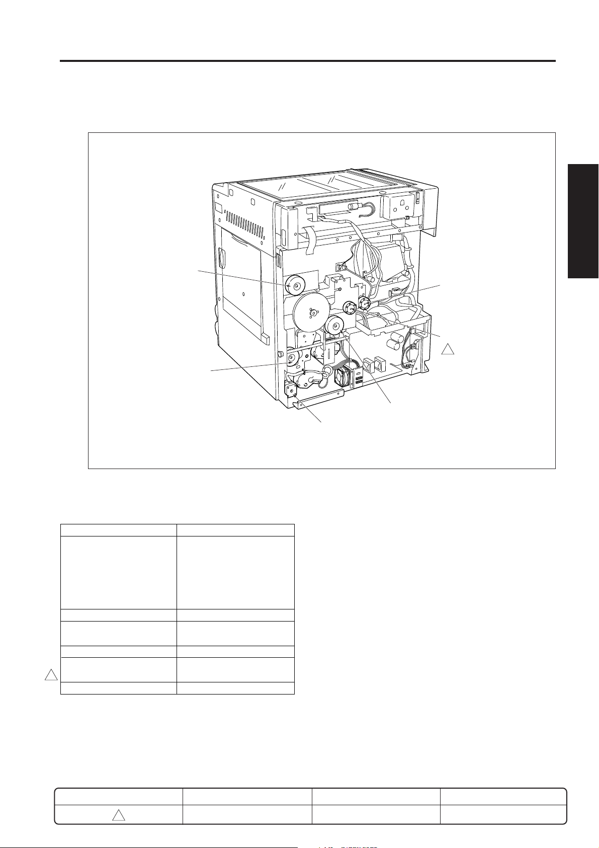
EXTERNAL SECTION
EXTERNAL SECTION
[1] Composition
Sub power switch
(SW2)
Main power switch
(SW1)
1 OUTLINE
Platen cover (Option)
Operation panel
Exit tray
2 UNIT EXPLANATION
Front door
Upper tray
Lower tray
3 DIS./ASSEMBLY
By-pass tray
KRDS interface (serial)
3
ISW interface (parallel)
REVISED EDITION
3
ADU door
DATE
Jan. 2002
2-A-1
PA GE
2-A-1
Rear cover
METHOD
REPLACEMENT
Page 3
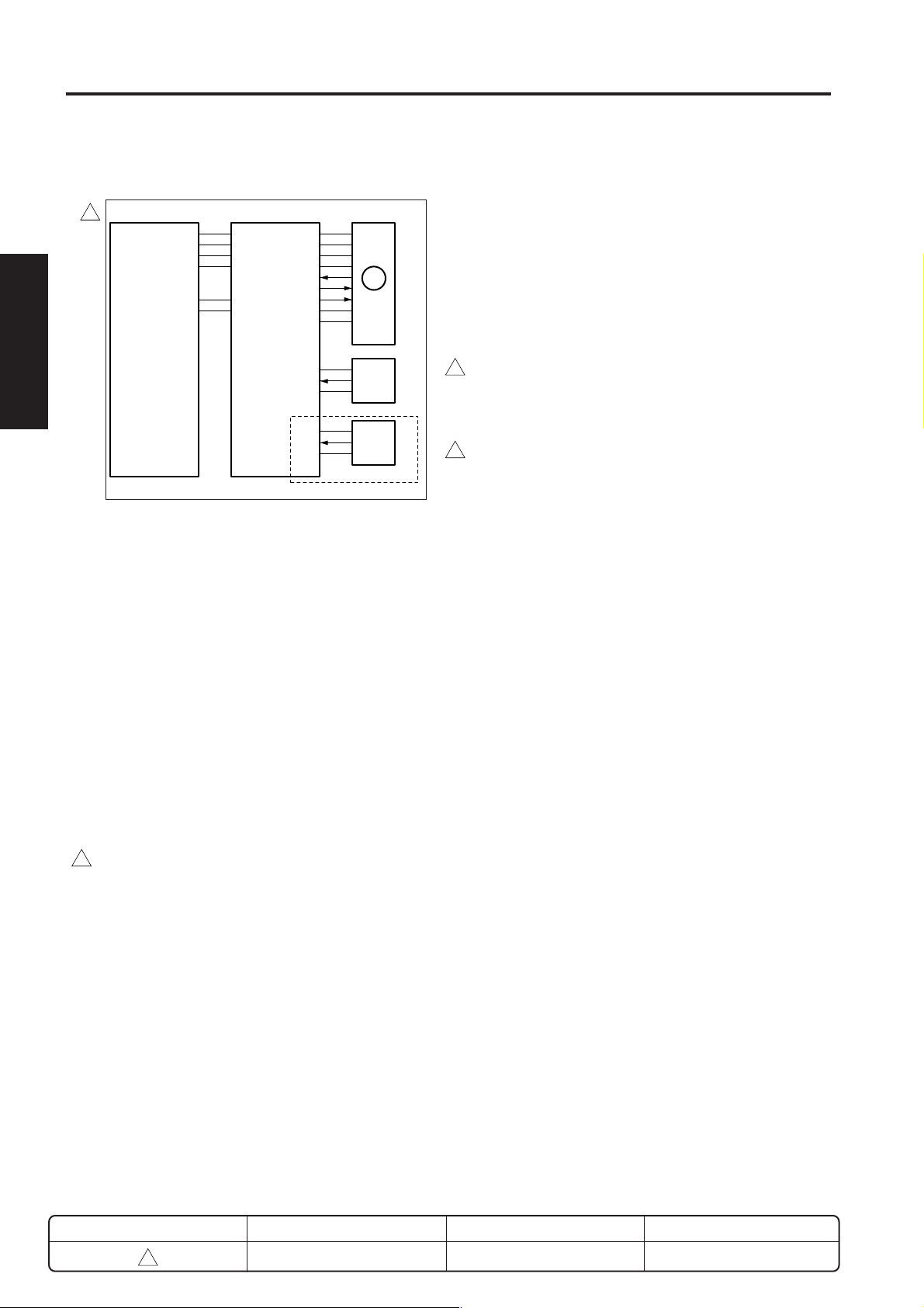
DRIVE SECTION
DRIVE SECTION
[1] Composition
Main motor (M1)
Paper feed drive
motor (M9)
Toner supply motor 1 (M4)
Toner supply motor 2 (M10)
* Other than 7020/25/30
3
Developing motor (M3)
1 OUTLINE
2 UNIT EXPLANATION
3 DIS./ASSEMBLY
[2] Mechanisms
Mechanism Method
Drum, Conveyance, Gear drive (M1)
Developer agitation,
Fixing, and exit drive,
ADU conveyance drive,
IT conveyance/exit
drive (when installing IT)
Developing sleeve drive Gear drive (M3)
Paper feed drive, ADU Gear drive (M9)
conveyance drive
Toner supply drive Gear drive (M4)
Toner bottle rotation drive Gear drive (M10)
(Other than 7020/25/30)
3
ADU drive Gear drive (M6) *1
ADU motor (M6)
REVISED EDITION
3
DATE
Jan. 2002
2-B-1
PAG E
2-B-1
METHOD
REPLACEMENT
Page 4
DRIVE SECTION
1 OUTLINE
2
2 UNIT EXPLANATION
3 DIS./ASSEMBLY
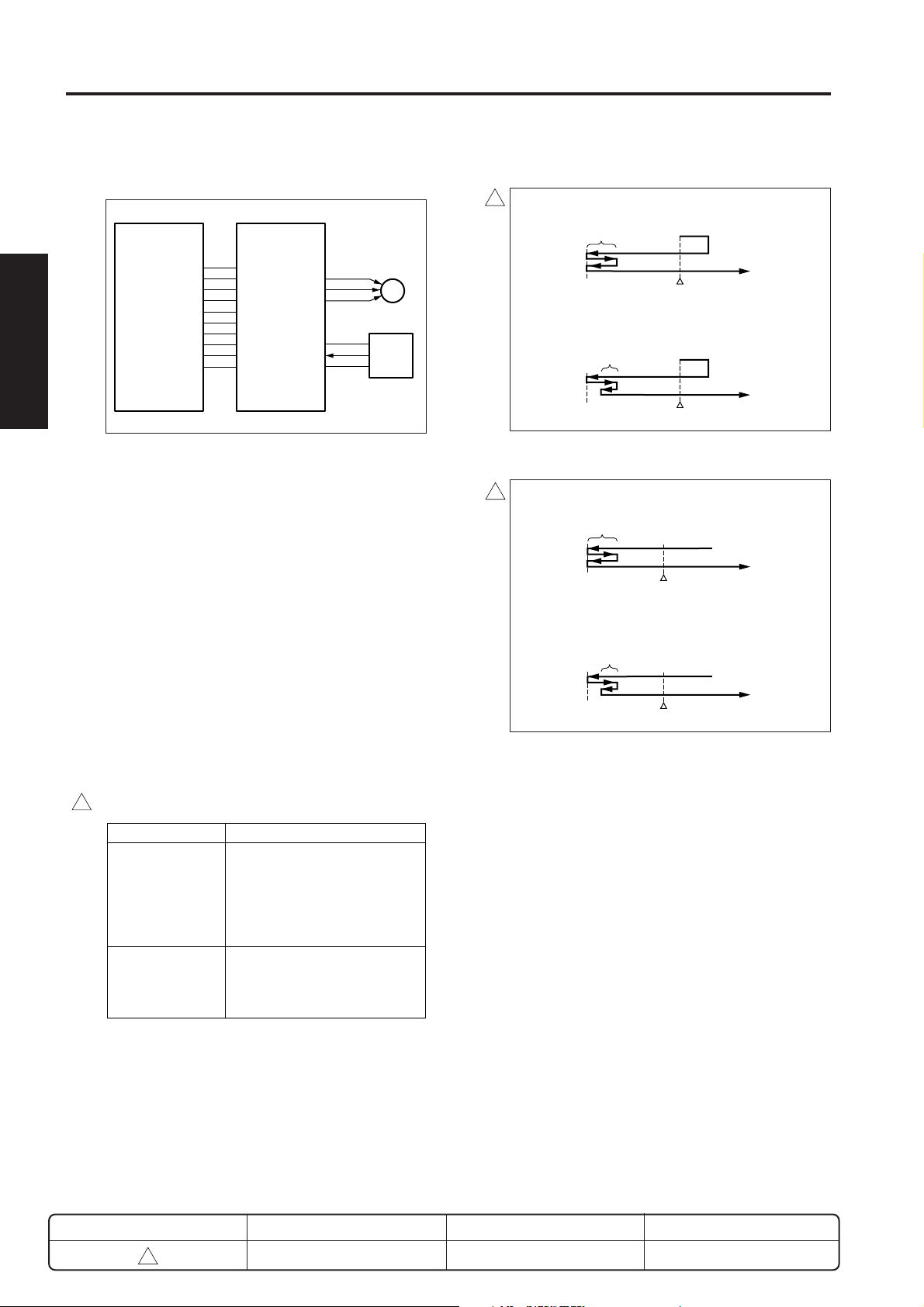
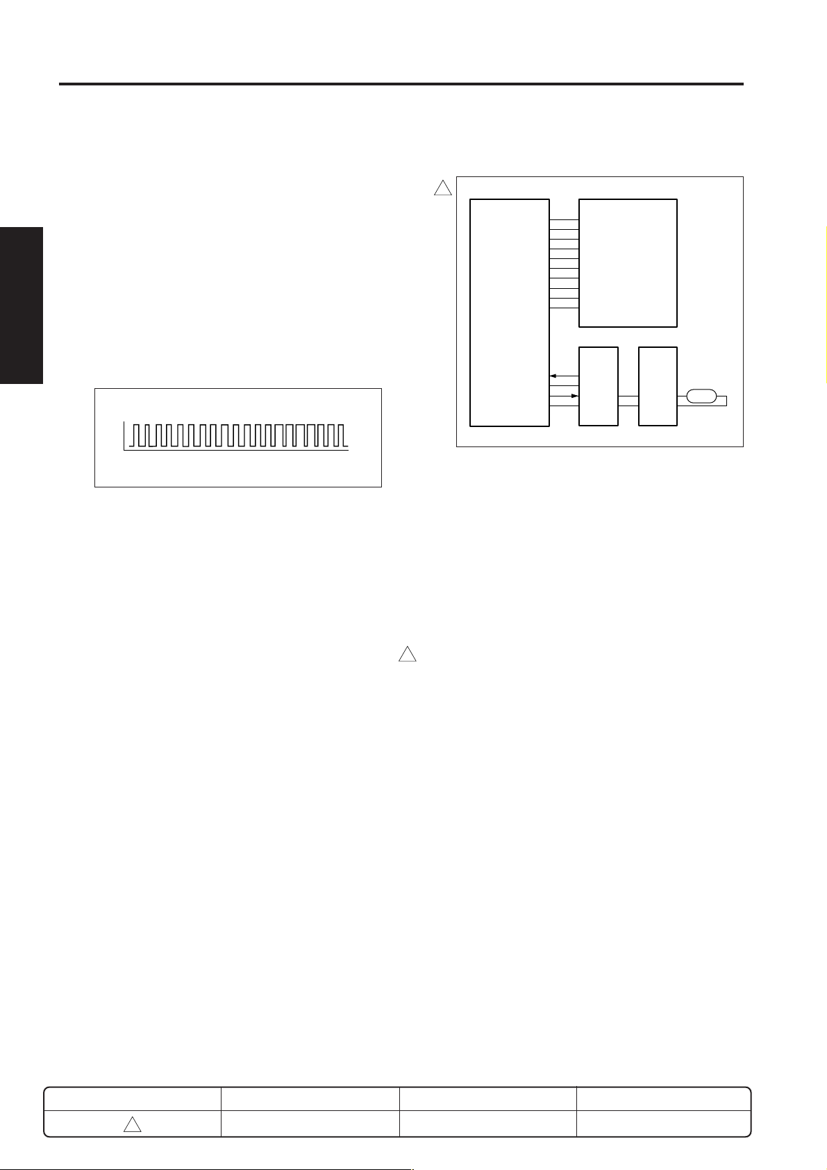
[3] M1 (main motor) control
3
24VDC
24VDC
PGND
PGND
SGND
5VDC
DCPS
M1 (main motor) is controlled by the PRDB (printer drive
board).
1. Operation
M1 is a brushless motor running on 24 VDC. It drives
the 2nd paper feed, fixing, drum, toner conveyance
screw and toner recycle screw, and also drives part
of the developer agitation screw, IT drive coupling
and the ADU conveyance section.
PRDB
24VDC
24VDC
PGND
PGND
LOCK SIG
M1 CLK
M1 CONT
5VDC
SGND
5VDC
PS2
SGND
SGND
PS3
5VDC
M1
PS2
PS3
7020/25/30/35
2. Signals
a. Input signals
(1) LOCK SIG (M1 → PRDB)
A monitoring signal for the rotation of M1.
Goes [L] when M1 rotation reaches the rated speed.
[H]: Stopped, or rotating at other than rated speed.
[L]: Rotating at rated speed. (PLL: stable)
(2) PS2 (PS2 → PRDB)
3
Paper fixing unit exit passage detection signal
[H] when paper is detected.
(3) PS3 (PS3 → PRDB)(Only for 7020/25/30/35)
3
Paper exit passage detect signal
b. Output signals
(1) M1 CONT (PRDB → M1)
M1 drive control signal.
[L]: M1 ON
[H]: M1 OFF
(2) M1 CLK (PRDB → M1)
Reference clock for M1 rotation control.
When IT is installed, M1 drives IT conveyance section and also drives the paper exit section via the IT
drive coupling.
M1 includes an internal speed sensor, and utilizes
PLL control to maintain constant speed. Rotational
speed is controlled by a reference clock signal output
by PRDB.
M1 comes ON when the START button is pressed, and
3
goes OFF at a predetermined time interval after PS3
(paper exit PS) (PS2 (fixing exit PS) in the case of
machines other than 7020/25/30/35) goes OFF for
the final copy.
At warm-up start, M1 comes ON. only during initial
drum charging.
REVISED EDITION
3
DATE
Jan. 2002
2-B-2
PA GE
2-B-2
METHOD
REPLACEMENT
Page 5

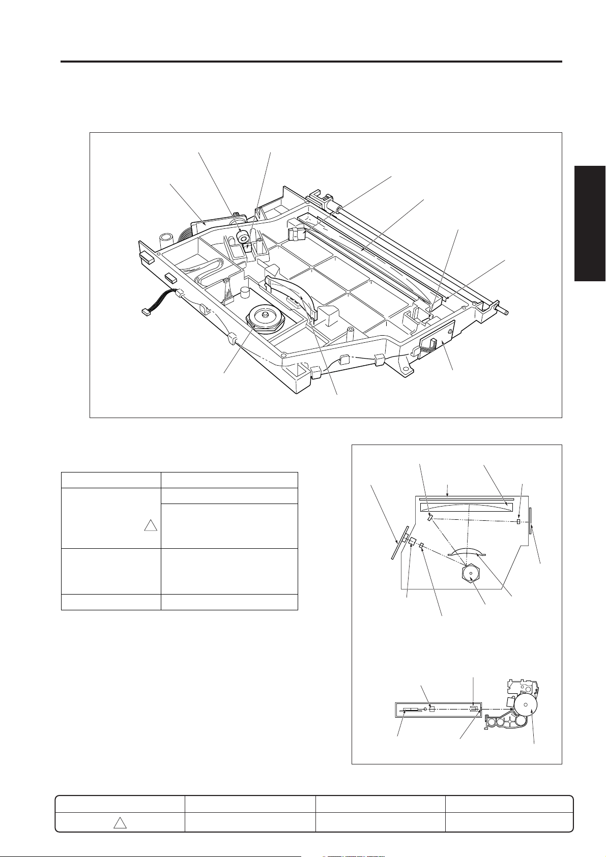
READ SECTION
READ SECTION
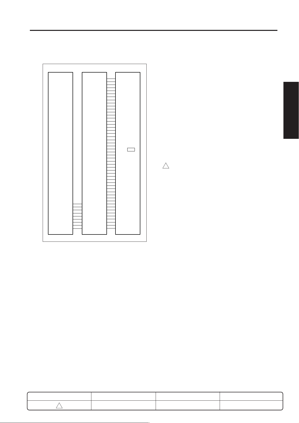
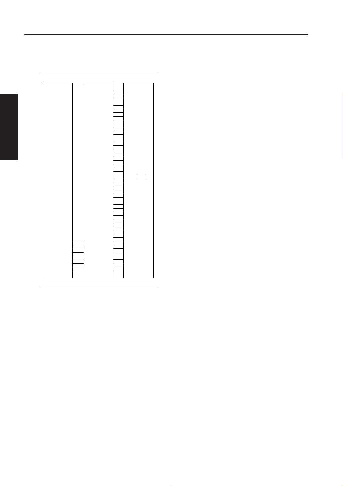
[1] Composition
V mirror unit
2nd mirror
3rd mirror
V mirror unit
CCD unit (AD converter
board (ADB))
1st mirror
Home-position
sensor (PS14)
Exposure unit
APS sensors 1 and 2 *
Optics wires
Optical motor (M2)
* : APS sensor 1 (PS17) is not installed on the 7022/7130.
3
(PS17, PS18)
Exposure-lamp
inverter (INV1)
Scanner drive
board (SCDB)
1 OUTLINE
2 UNIT EXPLANATION
3 DIS./ASSEMBLY
[2] Mechanisms
Mechanism Method
Light source Xenon lamp
Exposure Light source slit exposure
Scanning * Platen original scanning:
Movement of 1st, 2nd,
and 3rd mirrors.
RADF original scanning:
Original is moved with light
source held stationary.
Lamp power supply Lamp cord
* Platen and RADF scans operate as follows.
a. Platen original: The original is placed on the platen
glass, and reading is accomplished by movement
of the exposure unit and V mirror unit.
b. RADF original: The exposure unit and V mirror unit
are shifted under slit glass, and the original is
scanned as it passes over the exposure unit.
Slit glass
V mirror unit
Platen original
RADF original
Exposure unit
CCD unit
REVISED EDITION
3
DATE
Jan. 2002
2-C-1
PA GE
2-C-1
METHOD
REPLACEMENT
Page 6
READ SECTION
3
3
1 OUTLINE
2
2 UNIT EXPLANATION
3 DIS./ASSEMBLY
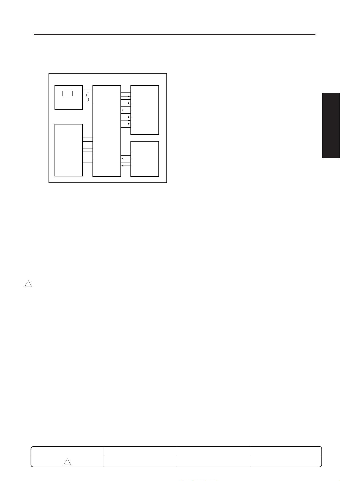
[3] M2 (optical motor) control
24VDC
24VDC
24VDC
PGND
PGND
PGND
5VDC
5VDC
SGND
SGND
DCPS
SCDB
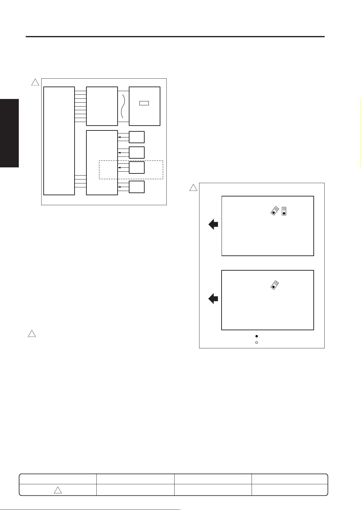
M2 (optical motor) is controlled by the SCDB (scanner
drive board). A related signal is provided by PS14 (optics
home position PS).
1. Operation
a. Operation of M2
M2 is a 3 phase stepping motor running on 24VDC.
This motor drives the exposure unit so as to
implement scanning. Forward rotation, reverse
rotation, and rotation speed are switched as
necessary to carry out each scan cycle.
The exposure unit's home position is detected by
PS14. M2 operation (drive time span and drive
direction) is controlled by time count after PS14 ON
or PS14 OFF.
b. Exposure unit’s scan speed
Scan Speed
3
Scan Speed
Forward <Other than 7035>
140mm/sec
(1:1 magnification)
<7035>
80mm/sec
(1:1 magnification)
Reverse <Other than 7035>
241mm/sec (max)
<7035>
310mm/sec (max)
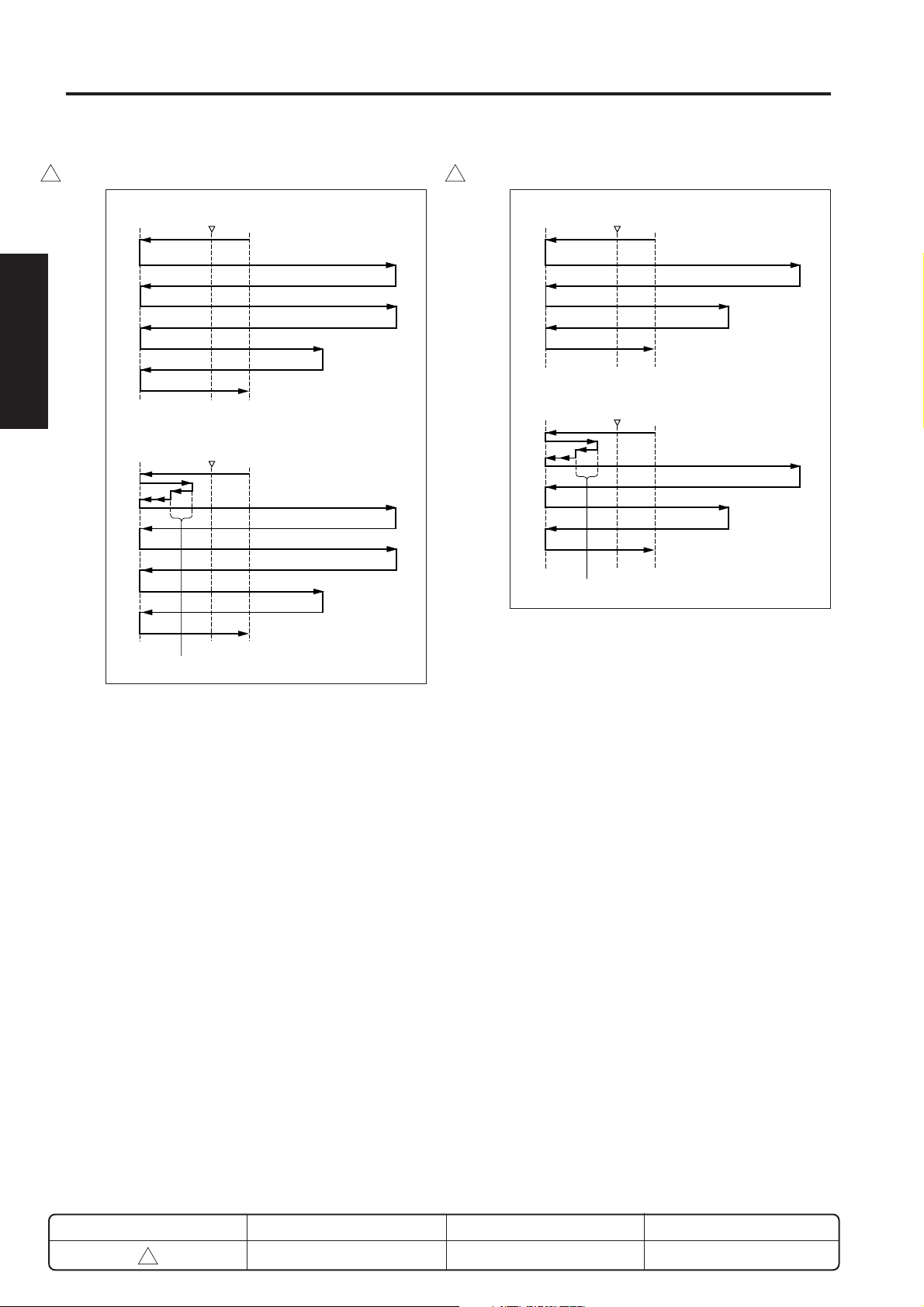
c. Initial operation when power is turned ON
When SW2 (sub power switch) comes ON, the
exposure unit starts a home position search. The
search procedure differs according to whether PS14
is ON or OFF. Upon completing the search, the
exposure unit stands by at the platen mode's APS
reading position.
SGND
OPT_HOME
5VDC
U
V
W
M2
PS14
(1) When PS14 is turned ON
<7020/25/30>
Shading correction
reading
Reference point
<Other than 7020/25/30>
Shading correction
reading
Reference point
PS14
PS14
Platen APS
reading position
Platen APS
reading position
(2) When PS14 is goes OFF
<7020/25/30>
Shading correction
reading
Reference point
<Other than 7020/25/30>
Shading correction
reading
Reference point
PS14
PS14
Platen APS
reading position
Platen APS
reading position
d. Shading correction reading
Shading correction read out is implemented using the
white reference plate attached beneath the glass
stopper plate. Shading correction is executed when
SW2 comes ON.
In the case of the 7035, shading correction is
performed when SW2 is turned ON, and also during
each scanning job.
e. Exposure scanning modes
Two modes are implemented: platen mode and DF mode.
In platen mode, the exposure unit moves as necessary
to scan the original. In DF mode, the RADF side
moves the original while the exposure unit stays fixed
in a specified position (the DF reading position).
REVISED EDITION
DATE
PA GE
METHOD
2-C-2
3
Jan. 2002
2-C-2
REPLACEMENT
Page 7

READ SECTION
f. Operation in DF mode
The read position in the DF mode is on the paper exit side
3
of PS14, and the exposure unit moves from the standby
position (platen APS read position) to the DF read
position. In the case of the 7035, shading correction
takes place while the exposure unit is moving to the DF
read position.
It then returns to the platen APS reading position after
completing the original scan and again enters standby.
3
<Other than 7035>
DF reading
position
Reference point
<7035>
DF reading
position
Shading correction reading
Reference point
Platen APS
reading position
PS14
Platen APS
reading position
PS14
(1) AE mode
<Other than 7035>
3
Reference point
<7035>
Reference
point
Shading correction reading
(2) Manual copy mode
PS14
PS14
1 OUTLINE
AE scan
Exposure scan
Platen APS
reading position
2 UNIT EXPLANATION
AE scan
Exposure scan
Platen APS
reading position
3 DIS./ASSEMBLY
g. Operation in platen mode
In this mode, the scan sequence depends on the
copy density selection (either AE or manual).
When the start button is pressed
When the AE mode is selected, the AE scan takes
3
place. When the AE mode is not selected, an
exposure scan takes place immediately. In the case
of the 7035, shading correction is performed before
the commencement of scanning, for all operations.
After completing the scan, exposure unit turns to the
platen APS reading position.
3
<Other than 7035>
Reference point
<7035>
Reference
point
PS14
Exposure scan
Platen APS
reading position
PS14
Exposure scan
Platen APS
reading position
Shading correction reading
REVISED EDITION
3
DATE
Jan. 2002
2-C-3
PA GE
2-C-3
METHOD
REPLACEMENT
Page 8
READ SECTION
1 OUTLINE
3 3
<Other than 7035>
PS14
2
2 UNIT EXPLANATION
Reference point
<7035>
PS14
AE scan
Exposure scan (Latter half)
Exposure scan (First half)
Platen APS
reading position
AE scan
Exposure scan (Latter half)
Exposure scan (First half)
3 DIS./ASSEMBLY
Platen APS
Reference
point
Shading correction reading
reading position
(4) Dual page (Manual mode, Left binding) mode(3) Dual page (AE mode, Left binding) mode
<Other than 7035>
Reference point
<7035>
Reference
point
PS14
Exposure scan (Latter half)
Exposure scan (First half)
Platen APS
reading position
PS14
Exposure scan (Latter half)
Exposure scan (First half)
Platen APS
reading position
Shading correction reading
REVISED EDITION
3
DATE
Jan. 2002
2-C-4
PA GE
2-C-3-1
METHOD
REPLACEMENT
Page 9
READ SECTION
2
2. Signals
1 OUTLINE
a. Input signal
[4] Exposure control
2
(1) OPT_HOME (PS14 → SCDB)
Exposure unit's home position detect signal.
[L]: Exposure unit is in home position.
[H]: Exposure unit out of home position.
b. Output signal
(1) M2 U, V, W (SCDB → M2)
2 UNIT EXPLANATION
M2 (Optical motor) ON/OFF drive signals.
24V
0V
3 DIS./ASSEMBLY
24VDC
24VDC
24VDC
PGND
PGND
PGND
5VDC
5VDC
SGND
SGND
DCPS
L1 EM
PGND
LAMP_ON/OFF
24VDC
SCDB
LV
HV
INV1 L1INVB
L1
Power for L1 (exposure lamp) is supplied by INV1
(exposure lamp inverter). This action is controlled by the
SCDB (scanner drive board).
1. Operation
L1 is a xenon lamp, and is driven by an inverter
circuit. Since the xenon lamp provides a stable light
intensity with low heat generation, it does not require
light intensity control circuit or overheat protection
circuit.
2. Signals
2
a. Input signal
(1) L1 EM (INV1 → SCDB)
1NV1 error detect signal
Enabled only when LAMP_ON/OFF is ON [L].
[L]: L1 ON
[H]: L1 OFF
* L1 EM is always High when LAMP_ON/OFF is OFF [H].
b. Output signal
(1) LAMP_ON/OFF (SCDB → INV1)
L1 ON/OFF control signal.
[L]: L1 ON
[H]: L1 OFF
REVISED EDITION
DATE
PA GE
METHOD
2-C-6
2
Feb. 2001
2-C-4
REPLACEMENT
Page 10
READ SECTION
[5] Original reading control
5VDC
5VDC
SGND
SGND
12VDC
SGND
-12VDC
SGND
DCPS
12VDC
CB
SGND
YCK 1
SGND
RCK
SGND
YG
SGND
CLAMP
SGND
SCK
SIN
SLD
MD0
MD1
MD2
SGND
OD0
OD1
OD2
OD3
SGND
OD4
OD5
OD6
OD7
SGND
ED0
ED1
ED2
ED3
SGND
ED4
ED5
ED6
ED7
APR
12VDC
12VDC
12VDC
12VDC
SGND
5VDC
5VDC
5VDC
5VDC
SGND
-5VDC
-5VDC
-5VDC
-5VDC
ADB
CCD
1. Operation
The light from the exposure lamp reflects back from
the original, passes through a lens, and hits the CCD
sensor. The CCD sensor generates an analog
electrical signal corresponding to the light intensity.
The ADB (A/D conversion board) then converts this
signal into a digital signal.
a. Original reading
The reading timing is as follows.
(1) Platen mode
Reading starts at a predetermined time interval after
the START button is pressed and when the exposure
unit has moved 6mm in the paper feed direction after
PS14 (optics home position) goes OFF.
(2) DF mode
When the leading edge of the original turns ON
1
PS311 (original registration PS) then moves a further
24.1 mm.
1 OUTLINE
2 UNIT EXPLANATION
3 DIS./ASSEMBLY
Original reading is carried out by the CCD sensor on the
ADB (A/D conversion board).
REVISED EDITION
1
DATE
May 2000
2-C-7
PA GE
2-C-5
METHOD
REPLACEMENT
Page 11
READ SECTION
3
1 OUTLINE
2
2 UNIT EXPLANATION
3 DIS./ASSEMBLY
[6] APS control
3
5VDC
5VDC
SGND
SGND
12VDC
SGND
-12VDC
SGND
DCPS
12VDC
5VDC
5VDC
SGND
SGND
CB
OPT_HOME
TIMING 1
APS_DATA 1
APS_DATA 2
SCDB
SGND
5VDC
SGND
5VDC
SGND
5VDC
SGND
5VDC
APS detection is carried out at opening or closing of the
RADF cover or original cover, and is controlled by the
SCDB (scanner drive board) based on signals from the
APS sensors and CCD sensor. Related signals are
provided by PS14 (optics home position PS), PS15 (APS
timing PS) and by PS304 (DF open/close PS) on the
RADF.
CCD
ADB
PS14
PS15
PS17
7020/25/30/35
PS18
L1 is ON during APS detection, so that the illumination level (light or dark level) in the main scanning differs according to whether the original is present or
absent. To detect line width (main scanning width),
the CCD sensor detects the difference from sky shot
black level to paper edge white level at each side. If
the RADF is installed, original size detection in the
main scanning is reexecuted when PS304 (DF open/
close PS) comes ON, so as to confirm the original
size.
The two APS sensors (PS17 and PS18) each consist
of a photosensor and a LED. If the original is present
at the sensor position, the light generated by the LED
reflects from the original and is detected by the
photosensor
<7020/25/30/35>
Exit
side
PS17 PS18
<Other than 7020/25/30/35>
1. Operation
a. APS detect operation
APS detection operation differs according to whether
operation is in platen mode or DF mode.
(1) Platen mode
Caution : In the case of machines other than
3
Size is detected by the combination of the ON/OFF
action of PS17 and PS18 (APS sensor 2) and the
detect signal from the CCD sensor on the ADB (A/D
conversion board).
PS17 and PS18 detect the original size in the sub
scanning direction, while the CCD sensor detects the
size in the main scanning direction.
7020/25/30/35, the PS17 (APS sensor 1)
is not installed.
Exit
side
PS18
: Photosensor
: LED
(2) DF mode
Original size detection is carried out by ON/OFF
action of PS306 (original size detect PS 1), and
PS307 (original size detect PS 2), and by the
resistance level of VR301 (original size detect VR)
located in the RADF paper feed tray.
REVISED EDITION
3
DATE
Jan. 2002
2-C-8
PAG E
2-C-6
METHOD
REPLACEMENT
Page 12

READ SECTION
The following table shows the relation between the
PS sensors and detected original sizes.
Sensor
Original Size
A3
11 × 17
B4
8.5 × 14
F4(8.5 × 13R)
8.5 × 11R
A4R
A4
8.5 × 11
B5
A5
B5R
A5R
B6R
PS17
PS306
ON
ON
ON
ON
ON
ON
ON
OFF
OFF
OFF
OFF
OFF
OFF
OFF
PS18
PS307
ON
ON
ON
ON
ON
OFF
OFF
OFF
OFF
OFF
OFF
OFF
OFF
OFF
ON : Original detected
OFF : Original not detected
2. Signals
a. Input signals
(1) TIMING1 (PS15 → SCDB)
RADF cover or platen cover open/close detect signal.
[L]: ON (Execute APS)
[H]: OFF (Cancel APS)
(2) APS_DATA1 (PS17 → SCDB)
(7020/25/30/35 only)
3
Original size detect signal.
[L]: Original detected.
[H]: Original not detected.
(3) ASP_DATA2 (PS18 → SCDB)
Original size detect signal.
[L]: Original detected.
[H]: Original not detected.
1 OUTLINE
2 UNIT EXPLANATION
3 DIS./ASSEMBLY
Caution : In the case of machines other than the
3
7020/25/30/35, read PS17 in the above
table as PS18. Also, note that the ON/
OFF operation due to PS18 in the table
does not take place.
b. APS detection timing
APS detection timing differs according to whether
operation is in platen mode or DF mode.
(1) Platen mode
Detection is carried out when PS15 (APS timing PS)
comes ON.
• If the RADF is installed, detection is carried out
again when PS304 (DF open/close PS) comes
ON.
• If the platen cover or RADF is open, detection is
carried out when the START button comes ON.
(2) DF mode
If DF mode has been selected or if an original is set in
the RADF paper feed tray, detection is carried out
using PS306 (original size detect PS 1), PS307
(original size detect PS 2), and VR301 (original size
detect VR).
REVISED EDITION
3
DATE
Jan. 2002
2-C-9
PA GE
2-C-7
METHOD
REPLACEMENT
Page 13
READ SECTION
1 OUTLINE
2
2 UNIT EXPLANATION
3 DIS./ASSEMBLY
[7] AE control
SGND
YCK 1
SGND
RCK
SGND
YG
SGND
CLAMP
SGND
SCK
SIN
SLD
MD0
MD1
MD2
SGND
OD0
OD1
OD2
OD3
SGND
OD4
OD5
OD6
CCD
OD7
SGND
ED0
ED1
ED2
ED3
SGND
ED4
ED5
ED6
ED7
APR
12VDC
12VDC
12VDC
12VDC
SGND
5VDC
5VDC
SGND
SGND
12VDC
SGND
-12VDC
SGND
DCPS
12VDC
CB
During AE scan, the CCD sensor on the ADB (A/D
conversion board) reads the density level of the original.
The CPU on the CB (overall control board) processes the
data and, based on the results, selects the gamma
correction curve that will best reproduce the original.
5VDC
5VDC
5VDC
5VDC
SGND
-5VDC
-5VDC
-5VDC
-5VDC
ADB
1. Operation
a. AE detect operation
(1) Platen copy
AE scanning is carried out when the START button is
pressed. The operation measures density over the
range described below.
<AE sampling range>
1) If the platen cover or RADF cover is open,
sampling is carried out to the boundaries of the
non image area erase or within the area detected
by APS.
2) If the platen cover or RADF cover is closed,
scanning is carried out over the range from the
center to 20mm away from each edge of the
original, as detected by APS.
• If APS is unable to detect the size, sampling is
carried out up to 20mm short of the minimum
supported original size in each direction.
(2) DF mode (1-1)
Pressing the START button causes the original to
feed. The leading area of the original is read, and
density is measured based on the read data. The
sampling range is as follows.
<AE sampling range>
1) In the main scanning direction
Sampling is carried out to the boundaries of the
non image area erase or within the area detected
by APS.
• Sampling is carried out over the range from the
center to 20mm away from each edge of the
original, as detected by APS.
• If APS is unable to detect the size, scanning is
carried out up to 20mm short of the minimum
suppoted original size in each direction.
2) In the sub scanning direction
Sampling starts 1.5mm from the leading edge and
ends 2.9mm from the leading edge.
2-C-8
Page 14
WRITE UNIT
[1] Composition
WRITE UNIT
1 OUTLINE
1 OUTLINE
Collimater lens unit
LD drive board (LDB)
Polygon motor
Cylindrical lens 1
fθ lens
Index mirror
Cylindrical lens 2
Index lens
Index sensor board (INDEX)
Dust-proof
glass
2 UNIT EXPLANATION
2 UNIT EXPLANATION
3 DIS./ASSEMBLY
3 DIS./ASSEMBLY
[2] Mechanisms
Mechanism Method
Scan *
Light source Laser diode
• Output: Max. 5mW
• Wavelength: 780nm
Positioning Index sensor
* : Path of laser light
The light output from semiconductor laser is radiated
onto the opc drum via the collimater lens, cylindrical
lens 1, polygon mirror, fθ lens, cylindrical lens 2.
Polygon mirror
Rotational speed
3
Other than 7035 : 33070.9 rpm
7035 : 42519.6 rpm
Index mirror
LD drive board
(LDB)
Collimater lens unit
fθ lens
Dust-proof glass
Polygon mirror
Cylindrical lens 1
Cylindrical lens 2
Dust-proof glassPolygon mirror
Cylindrical
lens 2
Index lens
Index sensor
board
fθ lens
OPC drum
REVISED EDITION
3
DATE
Jan. 2002
2-D-1
PA GE
2-D-1
METHOD
REPLACEMENT
Page 15

WRITE UNIT
1 OUTLINE
1 OUTLINE
2
2
2 UNIT EXPLANATION
2 UNIT EXPLANATION
3 DIS./ASSEMBLY
3 DIS./ASSEMBLY
[3] M5 (polygon motor) control
POLY LOCK
POLY CLK
POLY CONT
PGND
PGND
24VDC
DCPS
M5 (polygon motor) is controlled by the PRDB (printer
drive board).
24VDC
PRDB
1. Operation
a. M5 is a brushless motor running on 24V DC
power. The motor turns the polygon mirror,
causing the laser beam from the LDB (LD drive
board) to scan along the drum shaft direction.
M5 includes an internal speed sensor, and uti-
lizes PLL control to maintain a constant speed.
M5
2. Signals
a. Input signal
(1) POLY LOCK (M5 → PRDB)
M5 status detect signal.
[L] when M5 rotation reaches the rated speed.
b. Output signals
(1) POLY CONT (PRDB → M5)
M5 drive control signal.
[L]: M5 ON
[H]: M5 OFF
(2) POLY CLK (PRDB → M5)
Reference clock for M5 rotation control.
b. M5 rotation speed is as follows.
3
Machine State Rotation Speed
Copying
Idling Any of the following three
* If one of these speeds has been selected, M5
rotation speed will change at a specified time
upon completion of warm up or completion of
copy processing. You can select this time period,
using "25" mode, to any of the following: 15 sec,
30 sec. 60 sec, 120 sec.
33070.9 rpm (Other than 7035)
42519.6 rpm (7035)
speeds can be selected by
using "25" mode.
Other than 7035
33070.9 rpm
16000 rpm*
42519.6 rpm
25000 rpm*
Stop*
7035
REVISED EDITION
3
DATE
Jan. 2002
2-D-PB
PA GE
2-D-2
METHOD
REPLACEMENT
Page 16
WRITE UNIT
[4] Image write control
5VDC
CCD
ADB
5VDC
5VDC
SGND
SGND
12VDC
SGND
SGND
12VDC
DCPS
The CCD sensor outputs analog image data. The ADB (A/
D conversion board) converts this data to digital form. The
CB (overall control board) processes this data within
memory, generating a laser recording signal. This signal is
transmitted, by means of a CB control signal, to the LDB
(LD drive board), and is output as an optical signal by the
LDB's laser emitting element. The write start position for
the laser recording signal is detected by the index sensor
on the index sensor board.
SGND
/ENB
/VIDEO
SGND
/ALM
DACLK
LDPR+5VDC
5VDC
SGND
SGND
INDPR+5VDC
CB
/S/H
/IND
NC
DI
LD
LDB
INDEX
(3) Shading correction
<Execution timing>
White correction / Black correct
• At SW2 (sub power switch) ON
(4) Brightness/density conversion
(5) AE processing
(6) Text/dot pattern judgment
(7) Filtering
(8) Magnification change processing
(9) Error diffusion processing
(10) Data compression processing
(11) Write density correction
b. Write
CB transmits image data one pixel by one pixel to the
LDB. The LDB emits the laser onto the drum in
certain time for each pixel determined by the image
data received from the CB.
(1) MPC (Maximum Power Control)
The CB informs LDB of the maximum laser output
value. The LDB keeps and uses this value in APC
(automatic power control) to maintain the laser
intensity.
1 OUTLINE
1 OUTLINE
2 UNIT EXPLANATION
2 UNIT EXPLANATION
3 DIS./ASSEMBLY
3 DIS./ASSEMBLY
1. Operation
a. Image processing
3
The CB carries out the following processing.
(1) AOC (automatic offset correction)
Reading is taken with SW2 (sub power switch) ON
and L1 (exposure lamp) OFF, and the analog offset
voltage for CCD sencer output is automatically
adjusted such that this level become the lower limit
for the A/D converter (In the case of the other than
7035).
In the case of the 7035, IC on ADB automatically
adjusts analog off set voltage of CCD sensor output.
(2) AGC (automatic gain correction)
When SW2 comes ON, the level from the white
reference board is read by turning ON the L1
(exposure lamp), and the analog amplification for the
CCD sensor output is automatically adjusted such
that this level becomes the upper limit for the A/D
converter.
<MPC Timing>
(1) After SW2 is set at ON when L detection
adjustment has been completed or the drum
counter has been reset.
(2) When SW is turn ON first thing in the morning.
(3) Every 20th copy during a continuous copy
operation.
(2) APC (Automatic Power Control)
After the CB has set the MPC, it outputs an APC start
command to the LDB in accordance with the following
timing.
<APC Timing>
At detection of M5 (polygon motor) PLL lock.
Thereafter, LDB automatically monitors the laser
drive current for each line, and controls the laser such
that the light intensity is always at MPC.
(3) Write timing
The index board's /IND signal determines the start
time for laser writing of each scan in the drum shaft
direction.
REVISED EDITION
3
DATE
Feb. 2001
2-D-3
PA GE
2-D-3
METHOD
REPLACEMENT
Page 17

1 OUTLINE
1 OUTLINE
2
2
2 UNIT EXPLANATION
2 UNIT EXPLANATION
WRITE UNIT
2. Signals
2
a. Input signals
(1) /IND (INDEX → CB)
Index signal for write system.
(2) INDPR + 5VDC (INDEX → CB)
INDEX board detect connection monitor signal.
[H]: Not present
[L]: Present
(3) /ALM (LDB → CB)
Indicates abnormality in laser drive current (APC
operation).
[H]: Normal
[L]: Abnormal
(4) LDPR + 5VDC (LDB → CB)
LDB connection monitoring signal.
[H]: Not present
3 DIS./ASSEMBLY
3 DIS./ASSEMBLY
[L]: Present
b. Output signals
(1) /VIDEO (CB → LDB)
Image signal for / VIDEO laser.
(2) DACLK (CB → LDB)
Clock signal used for transfer of MPC data.
(3) DI (CB → LDB)
MPC data signal.
(4) LD (CB → LDB)
MPC data memorize command signal.
(5) /S/H (CB → LDB)
APC sampling signal (for one line).
(6) /ENB (CB → LDB)
ON/OFF control signal for laser APC function. If OFF,
laser output is stopped.
REVISED EDITION
2
DATE
Feb. 2001
2-D-PB
PA GE
2-D-4
METHOD
REPLACEMENT
Page 18

DRUM UNIT
DRUM UNIT
[1] Composition
1
Drum
Cleaning section
Separation
claws
Charging
corona unit
Cleaning/Toner-recycle section
PCL
Charging
corona unit
Developing unit
Transfer
corona unit
Paper entrance
guide plate
Separation
claws
Drum
Separation
corona unit
TSL
1 OUTLINE
2 UNIT EXPLANATION
3 DIS./ASSEMBLY
[2] Mechanisms
Mechanism Method
Pedestal hold Fixed rail
PCL LED
Auxiliary separation Separation claws *
The drum unit is a single unit consisting of the drum, the
charging corona unit, the cleaning, toner recycle section,
and the PCL.
REVISED EDITION
1
DATE
May 2000
2-E-1
* : Operation of the separation claws
When SD7 (separation claw SD) is activated, the rod
connected to it moves such that the cutouts on the
rod allow the claws to fall into contact with the drum
under their own weight. The contact of the claws aids
in paper separation.
1
Rod
Separation
claw SD (SD7)
PA GE
2-E-1
Separation
claws
METHOD
REPLACEMENT
Page 19

1 OUTLINE
2
2 UNIT EXPLANATION
3 DIS./ASSEMBLY
DRUM UNIT
[3] PCL/TSL control
3
24VDC
PCL CONT
24VDC
TSL DRIVE
5VDC
MC1 DRIVE
SGND
PS1
DCPS
24VDC
24VDC
PGND
PGND
SGND
5VDC
PRDB
5VDC
SVDzzc
PS2
SGND
SGND
PS3
5VDC
The PCL (pre-charging lamp) and TSL (transfer synchronization lamp) are LED type lamps, and are controlled by
the PRDB.
1. Operation
PCL lights when the START button is pressed, and
3
goes OFF after the specified period from when PS3
(paper exit PS) (or PS2 (fixing exit PS) for machines
other than the 7020/25/30/35) goes OFF (when the
final sheet of copy paper is exited). TSL comes ON at
a predetermined time interval after MC1 (registration
clutch) comes ON, and goes OFF at a predetermined
time interval after PS1 (registration PS) goes OFF.
2. Signals
a. Input signal
(1) PS1 (PS1 → PRDB)
Detection of paper at paper feed temporary stop
position.
PCL
TSL
MC1
PS1
PS2
PS3
7020/25/30/35
[4] Separation claws control
24VDC
SD7 DRIVE
5VDC
MC1 DRIVE
PRDB
DCPS
24VDC
24VDC
PGND
PGND
SGND
5VDC
The separation claws are driven by SD7 (separation claw
SD), which is controlled by the PRDB (printer drive board).
1. Operation
SD7 comes ON at a predetermined interval after MC1
(registration clutch) comes ON, causing the separation claws to make contact with the drum so as to assist in separating the paper from the drum.
2. Signals
a. Output signal
(1) SD7 DRIVE (PRDB → SD7)
SD7 drive control signal.
[L]: SD7 ON
[H]: SD7 OFF
SD7
MC1
[H] when paper is detected.
b. Output signals
(1) PCL DRIVE (PRDB → PCL)
PCL ON/OFF control signal.
[L]: PCL ON
[H]: PCL OFF
(2) TSL DRIVE (PRDB → TSL)
TSL ON/OFF control signal.
[L]: TSL ON
[H]: TSL OFF
REVISED EDITION
3
DATE
Jan. 2002
2-E-2
PAG E
2-E-2
METHOD
REPLACEMENT
Page 20

DRUM UNIT
[5] Paper entrance guide plate control
24VDC
24VDC
PGND
PGND
SGND
5VDC
DCPS
A fixed voltage is applied to the paper entrance guide plate
so as to prevent toner from sticking to the plate.
1. Operation
24VDC
24VDC
M1 LOCK SIG
M1 CLK
M1 CONT
GP CONT
PRDB
PGND
PGND
5VDC
SGND
PGND
24VDC
M1
GP
HV
1 OUTLINE
2 UNIT EXPLANATION
3 DIS./ASSEMBLY
a. ON/OFF timing
ON/OFF in sync with M1 (main motor).
b. Applied voltage
–500V DC (constant voltage)
2. Signals
a. Output signal
(1) GP CONT (PRDB → HV)
Controls application of fixed voltage to the paper
entrance guide plate.
[L]: Voltage applied
[H]: No voltage
2-E-3
Page 21

CORONA UNIT
CORONA UNIT
[1] Composition
<Charging-corona unit>
PCL
Charging control
plate
Charging wire
[2] Mechanisms
Mechanism Method
Charging
Transfer DC positive corona discharge
Separation AC/DC corona discharge
Scorotron (DC negative corona discharge)
Discharge wire:
Tungsten, φ0.06mm
(gold-plated skin path)
Grid control: Stainless-steel plate
with manual wire cleaning
feature
Discharge wire:
Oxide-coated tungsten, φ0.06mm
with manual wire cleaning
feature
Discharge wire:
Oxide-coated tungsten, φ0.06mm
with manual wire cleaning
feature
Charging-wire cleaning
material
Spark arrester
plate (front)
<Transfer/Separation corona unit>
Paper entrance guide plate
Separation wire
Transfer wire
Spark arrester
plate (rear)
Plunging
prevention plate
Power supply to the Transfer/Separation corona
unit
Caution: Do not carry out copying with the
ADU door open by forcibly setting
the interlock ON, as doing so will
generate high-voltage output at the
contacts (springs) on the main-body
board.
Closing of the ADU door establishes the connection to the
power supply.
1 OUTLINE
2 UNIT EXPLANATION
3 DIS./ASSEMBLY
2-F-1
ADU door
Contact point
Page 22

CORONA UNIT
1 OUTLINE
2
2 UNIT EXPLANATION
3 DIS./ASSEMBLY
[3] Charging control
1
24VDC
24VDC
PGND
PGND
M1 LOCK SIG
M1 CLK
M1 CONT
5VDC
SGND
PGND
24VDC
C CONT
C SHIFT
G SHIFT
F(C) SIG GRID
PRDB
DCPS
24VDC
24VDC
PGND
PGND
SGND
5VDC
The HV (high voltage unit) carries out charging by
outputting a high voltage onto the charging wire.
The HV is controlled by analog control signals output from
the PRDB (printer drive board).
1. Operation
The HV comes ON together with M1 (main motor),
and goes OFF at a predetermined time interval after
transfer output for the final sheet goes OFF.
a. Charging
An inverter boosts the 24VDC power from the DCPS,
generating a high negative DC voltage that is
discharged from the charging wire.
M1
CHARGING
HV
2. Signal
a. Input signal
(1) F (C) SIG (HV → PRDB)
[L] if charge output has been forcibly switched OFF
owing to detection of spark or occurrence of output
short.
b. Output signals
(1) C CONT (PRDB → HV)
Charge voltage and grid voltage ON/OFF control
signal.
[L]: Charge and grid voltages ON
[H]: Charge and grid voltages OFF
(2) C SHIFT (PRDB → HV)
Analog signal from PRDB; controls the output level of
the charging corona unit.
C SHIFT output range 4 to 10V
Charging output range –100 to –650µA
(3) G SHIFT (PRDB → HV)
Analog signal from PRDB; controls the output level of
the grid voltage.
1
G SHIFT output range 4 to 10V
Grid voltage output –450 to –1090V
range
b. Grid voltage
The HV applies grid voltage to the charging control
plate.
REVISED EDITION
1
DATE
May 2000
2-F-2
PA GE
2-F-2
METHOD
REPLACEMENT
Page 23

CORONA UNIT
[4] Transfer/Separation control
1
24VDC
MC1 DRIVE
SGND
PS1
5VDC
PGND
S SHIFT(AC)
S SHIFT(DC)
PRDB
24VDC
T CONT
T SHIFT
S CONT
F(T) SIG
F(S) SIG
DCPS
24VDC
24VDC
PGND
PGND
SGND
5VDC
The transfer/separation corona units are controlled by the
PRDB (printer drive board) and the HV (high voltage unit).
1. Operation
Transfer and separation come ON at predetermined
intervals after M1 (main motor) comes ON, and go
OFF at predetermined intervals after PS1 (registration
PS) goes OFF.
MC1
PS1
SEPARATION
TRANSFER
HV
2. Signals
a. Input signals
(1) F (T) SIG (HV → PRDB)
[L] if transfer output has been forcibly switched OFF
owing to detection of spark or occurrence of output
short.
(2) F (S) SIG (HV → PRDB)
[L] if separation output has been forcibly switched
OFF owing to detection of spark or occurrence of
output short.
b. Output signals
(1) T CONT (PRDB → HV)
Transfer corona unit ON/OFF control signal.
[L]: Transfer corona unit ON
(2) T SHIFT (PRDB → HV)
Transfer corona unit output control signal.
Analog signal from PRDB; controls the output level of
the transfer corona unit.
1 OUTLINE
2 UNIT EXPLANATION
3 DIS./ASSEMBLY
a. Transfer
Constant current is applied so as to produce a high
voltage DC discharge.
b. Separation
Constant voltage is applied to produce a high voltage
AC discharge, and constant current is applied to
produce high voltage DC discharge.
T SHIFT output range 4 to 10V
Transfer output range 0 to 350µA
(3) S CONT (PRDB → HV)
Separation corona unit ON/OFF control signal.
[L]: Separation corona unit ON
(4) S SHIFT (AC) (PRDB → HV)
Separation corona unit output control signal.
Analog signal from PRDB; controls the level of the
AC component of the separation corona unit.
S SHIFT (AC) output range 3 to 10V
Separation AC output range 1.5 to 5.0kV
(5) S SHIFT (DC) (PRDB → HV)
Separation corona unit output control signal.
Analog signal from PRDB; controls the level of the
DC component of the separation corona unit.
S SHIFT (DC) output range 4 to 10V
Separation DC output range 0 to –300µA
REVISED EDITION
1
DATE
May 2000
2-F-3
PA GE
2-F-3
METHOD
REPLACEMENT
Page 24

DEVELOPING UNIT
DEVELOPING UNIT
[1] Composition
1
Developing
sleeve
Developing
unit cover
Agitator screws
Developing
regulator plate
Agitator wheel
Developing
sleeve
1 OUTLINE
2 UNIT EXPLANATION
3 DIS./ASSEMBLY
[2] Mechanisms
Mechanism Method
Developing 2-component developing
Developing bias DC bias
Developer agitation Main and supplemental
agitation
Developing unit drive
The developing unit is driven by two different motors.
The developing motor (M3) drives the developing
sleeve, while the main motor (M1) drives the agitator
section.
REVISED EDITION
1
DATE
May 2000
2-G-1
PA GE
2-G-1
METHOD
REPLACEMENT
Page 25

DEVELOPING UNIT
1
1 OUTLINE
[3] M3 (developing motor) control
[4] Developing bias control
2
2 UNIT EXPLANATION
DCPS
24VDC
24VDC
PGND
PGND
SGND
5VDC
PRDB
24VDC
24VDC
PGND
PGND
SGND
M3 LD
M3 CLK
M3 CONT
SGND
5VDC
M3 (developing motor) is controlled by the PRDB (printer
drive board).
1. Operation
M3 runs on 24V DC power, and drives the developing
3 DIS./ASSEMBLY
sleeve. M1 drives the agitator wheel and agitator
screws. (For information about M1, refer to “M1 (Main
motor) control.”) M3 includes an internal speed sensor, and utilizes PLL control to maintain a constant
speed, using a reference clock signal output by
PRDB.
M3
DCPS
24VDC
24VDC
PGND
PGND
SGND
5VDC
24VDC
PGND
M3 CW/CCW
M3 CONT
B CONT
B SHIFT
PRDB
24VDC
24VDC
PGND
PGND
SGND
M3 LD
M3 CLK
SGND
5VDC
SGND
PS1
5VDC
M3
PS1
BIAS
HV
Developing bias is controlled by the PRDB (printer drive
board) and the HV (high voltage unit).
1. Operation
Application of developing bias to the developing
sleeve starts a predetermined time interval after M3
(developing motor) comes ON, and ends a
predetermined time interval after charging goes OFF.
M3 goes ON and OFF in sync with M1.
2. Signals
a. Input signal
(1) M3 LD (M3 → PRDB)
M3 status detect signal.
Goes [L] when M3 rotation reaches the rated speed.
[H]: Stopped, or rotating at other than rated speed.
[L]: Rotating at rated speed. (PLL: stable)
b. Output signals
(1) M3 CONT (PRDB → M3)
M3 drive control signal.
[L]: M3 ON
[H]: M3 OFF
(2) M3 CLK (PRDB → M3)
Reference clock for M3 rotation control.
2. Signals
a. Output signals
(1) B CONT (PRDB → HV)
Developing bias ON/OFF control signal.
[L] sets developing bias ON and outputs high voltage.
(2) B SHIFT (PRDB → HV)
Developing bias level control signal.
Analog signal from PRDB; controls the developing
bias output level.
B SHIFT output range 2 to 8V
Bias-Voltage output range –350 to –830V
REVISED EDITION
DATE
PA GE
METHOD
2-G-2
1
May 2000
2-G-2
REPLACEMENT
Page 26

DEVELOPING UNIT
3
[5] Toner density control
3
24VDC
24VDC
PGND
PGND
SGND
DCPS
5VDC
12VDC
SGND
M3 CW/CCW
M3 CONT
TDS CONT
TONER ANG
PRDB
24VDC
24VDC
PGND
PGND
SGND
M3 LD
M3 CLK
SGND
5VDC
A
A
B
B
24VDC
24VDC
A
A
B
B
24VDC
24VDC
Other than 7020/25/30
12VDC
SGND
SGND
PS1
5VDC
M3
M4
M10
TDS
PS1
(1) When the power switched ON
Following power on, M1 (main motor) turns the
3
agitator screws, and after a predetermined time
interval the TDS reads the toner density. The PRDB
compares the density detected by TDS with the
developer's initial density. If the detected density is
low, M4 and M10 (other than 7020/25/30) comes on
and supplies toner until the proper density level is
restored.
(2) During a copy operation
The following table shows the relation between TDS
output voltage and toner supply time.
TDS output voltage Replenishment Time
≤ 2.00 (2.01)V 0 sec.
2.01 to 2.05 (2.04)V 0.24 (0.10)sec.
2.06 (2.04) to 2.09 (2.08)V 0.48 (0.20)sec.
2.10 (2.08) to 2.13 (2.12)V 0.72 (0.30)sec.
2.14 (2.12) to 2.17 (2.19)V 0.96 (0.40)sec.
2.18 (2.19) to 2.21 (2.35)V 1.20 (0.50)sec.
≥ 2.22 (2.35)V 1.80 (0.70)sec.
Parenthesized values are for the 7035
1 OUTLINE
2 UNIT EXPLANATION
3 DIS./ASSEMBLY
Toner density is controlled by the TDS (toner density
3
sensor), M4 (toner supply motor 1), M10 (toner supply
motor 2: other than 7020/25/30) and the PRDB (printer
driver board).
1. Operation
a. Toner density control
The TDS uses L detection to detect the toner density
in the developing unit, and outputs to the PRDB an
analog signal corresponding to the detected density.
The PRDB determines whether toner supply is
necessary by comparing the detected value against
the developer's initial density.
b. Supply of toner to the developing unit
M4 and M10 (other than 7020/25/30) are stepping
3
motor running on 24VDC. Drive time is controlled by
the PRDB.
2. Signals
a. Input signal
(1) TONER ANG (TDS → PRDB)
Outputs an analog voltage corresponding to the toner
density.
b. Output signals
(1) TDS CONT (PRDB → TDS)
TDS output voltage adjustment signal.
Output range: 3 to 8 V
(2)
M4 A, A, B, B (PRDB → M4)
M4 drive control signals.
(3)
M10 A, A, B, B (PRDB → M10)
M10 drive control signals. (other than 7020/25/
)
30
REVISED EDITION
DATE
PA GE
METHOD
2-G-3
3
Jan. 2002
2-G-3
REPLACEMENT
Page 27

TONER SUPPLY UNIT
TONER SUPPLY UNIT
[1] Composition
Toner supply unit
Toner bottle
Toner supply paddle
Toner-cavity
prevention plate
Toner conveyance screw
1 OUTLINE
2 UNIT EXPLANATION
3 DIS./ASSEMBLY
[2] Mechanisms
Mechanism Method
Toner supply Screw conveyance
Toner level detection Piezoelectric method:
Approx. 30g
Toner agitation *1 Toner agitator plate + screw
Toner bottle *2 Rotation cartridge
Toner leak prevention Toner supply shutter
*1: Toner agitation
The toner agitator plate is powered by the toner
supply motor 1 (M4) via gears.
*2: Toner bottle
<Operation in the case of the 7020/25/30>
The toner bottle rotates while the toner bottle SD
(SD6) is ON. This rotation is driven by the toner
supply motor 1 (M4). Rotation causes the toner to
move toward the bottle outlet along the spiral
groove cut into the bottle surface.
<Operation in the case of the other than 7020/25/30>
3
When toner supply motor 2 (M10) goes ON, the
toner bottle rotates, causing the toner to move
along the spiral groove cut in the surface of the
toner bottle to the outlet of the toner bottle.
<Common Operation>
At the outlet of the toner bottle is a toner supply
paddle which pushes the toner to the agitation/
conveyance section of the toner supply unit along
with the rotation of the toner bottle.
Toner cavity
prevention plate
Toner conveyance screw
Toner supply paddle
REVISED EDITION
3
DATE
Jan. 2002
2-H-1
PA GE
2-H-1
METHOD
REPLACEMENT
Page 28

1 OUTLINE
2
2 UNIT EXPLANATION
TONER SUPPLY UNIT
[3] Toner level detection control
3
A
A
B
B
24VDC
24VDC
A
A
B
B
24VDC
24VDC
Other than 7020/25/30
5VDC
TLD
SGND
DCPS
24VDC
24VDC
PGND
PGND
SGND
5VDC
PRDB
M4
M10
TLD
[4] Toner bottle detection control
24VDC
24VDC
PGND
PGND
SGND
5VDC
DCPS
PS5 (toner bottle PS) detects the presence or absence of
the toner bottle.
PRDB
SGND
PS5 SIG
5VDC
PS5
Control of toner level detection is carried out by the TLD
(toner level detecter) and the PRDB (printer control board).
1. Operation
a. Toner level detection
3 DIS./ASSEMBLY
The TLD uses a piezo element. When TLD detects
that toner in the cartridge has run low, it outputs a
toner supply signal to the PRDB, generating a
message on the LCD (display board).
b. Detection timing
Detection is carried out at the following times.
• During copying
c. Toner supply operation to toner supply unit
<Operation in the case of the 7020/25/30>
When TLD detects that toner is empty, SD6 (tonerbottle SD) goes ON and engages the gear. When M4
(toner supply motor 1) goes ON, the bottle turns,
sending new toner to the toner supply unit.
1. Operation
PS5 detects mounting of the toner bottle, and the
machine enters copy standby.
2. Signal
a. Input signal
(1) PS5 SIG (PS5 → PRDB)
Toner bottle detect signal.
[H]: Toner bottle not present.
[L]: Toner bottle is present.
<Operating in the case of the other than 7020/25/30>
3
When the TLD detects that the toner is empty up,
M10 (toner supply motor 2) goes ON and rotates the
toner bottle, causing new toner to be supplied to the
toner supply unit.
2. Signals
a. Input signal
(1) TLD (TLD → PRDB)
Goes [L] when the quantity of toner in the toner
cartridge runs low. If [L] state continues for a
predetermined period, a corresponding message is
displayed in the LCD.
REVISED EDITION
3
DATE
Jan. 2002
2-H-2
PA GE
2-H-2
METHOD
REPLACEMENT
Page 29

CLEANING/TONER RECYCLE UNIT
CLEANING/TONER RECYCLE UNIT
[1] Composition
1
Cleaning blade
Collected toner conveyance screw
Collected toner
conveyance screw
Cleaning
blade
Toner
collection
sheet
1 OUTLINE
2 UNIT EXPLANATION
3 DIS./ASSEMBLY
[2] Mechanisms
Mechanism Method
Drum cleaning Cleaning blade
(spring load type)
Toner recycle* Toner conveyance by screw
Toner collection Toner collection sheet
*Toner recycle
Toner collected by the cleaning blade is conveyed
to the collected toner exit (and returned to the
toner supply unit) by the action of the collected
toner conveyance screw.
1
Collected toner
conveyance screw
REVISED EDITION
1
DATE
May 2000
2-I-1
PA GE
2-I-1
METHOD
REPLACEMENT
Page 30

PAPER FEED UNIT
PAPER FEED UNIT
[1] Composition
1
Upper tray
Lower tray
Paper feed roller
Paper lift-up plate
Paper feed roller
Paper lift-up plate
Double feed
prevention roller
/upper
Registration rollers
Double feed
prevention
roller
Loop rollers
By-pass conveyance roller
By-pass pick-up roller
By-pass reverse roller
Loop roller
Double feed prevention roller
/upper
Double feed prevention roller
1 OUTLINE
2 UNIT EXPLANATION
3 DIS./ASSEMBLY
[2] Mechanisms
Mechanism Method
Paper stacking Two trays
Paper lift-up Paper lift-up plate
Double feed prevention Torque limiter
Tray loading Front loading
First paper feed Paper feed SD
Paper feed roller
Loop clutch
Loop roller
Second paper feed Registration clutch
Registration rollers
By-pass feed By-pass feed SD
1
By-pass conveyance
rollers
Loop roller
Paper size detection Paper size setting unit
1
REVISED EDITION
1
May 2000
DATE
2-J-1
PA GE
2-J-1
METHOD
REPLACEMENT
Page 31

PAPER FEED UNIT
1 OUTLINE
2
2 UNIT EXPLANATION
3 DIS./ASSEMBLY
[3] Paper feed control
24VDC
24VDC
PGND
PGND
M9 CLK
M9 CONT
5VDC
SGND
SGND
PS1
5VDC
MC1 DRIVE
MC2 DRIVE
SD1 DRIVE
SD2 DRIVE
SD3 DRIVE
PRDB
24VDC
24VDC
24VDC
24VDC
24VDC
DCPS
24VDC
24VDC
PGND
PGND
SGND
5VDC
M9 (paper feed motor) drive power is transmitted to the
various rollers by means of SD1 (first paper feed SD (upper
tray)), SD2 (first paper feed SD (lower tray)), and SD3 (bypass SD). When M9 first comes ON, no rollers are in
contact with paper; accordingly, SD1, SD2, or SD3 operate
to raise or lower the feed rollers or by-pass plate so as to
make contact with paper and initiate feeding.
M9
PS1
MC1
MC2
SD1
SD2
SD3
1. Operation
a. Timing for first paper feed (by-pass)
(1) Start for first sheet
At a predetermined time interval after START button
ON.
(2) Start for second sheet
At a predetermined time interval after first sheet SD3
ON.
(3) OFF timing
At a predetermined time interval after SD3 ON.
b. Timing for first paper feed (upper tray)
(1) Start for first sheet
At a predetermined time interval after START button
ON.
(2) Start for second sheet
At a predetermined time interval after first sheet SD1
ON.
(3) OFF timing
At a predetermined time interval after SD1 ON.
c. Timing for first paper feed (lower tray)
(1) Start for first sheet
At a predetermined time interval after START button
ON.
When SD1 (first paper feed SD) comes ON, MC2 (loop
clutch) also comes ON at the same time, conveying the
paper up to the registration rollers. PS1 (registration PS)
detects the leading edge of the paper, MC2 goes OFF,
and the paper is formed into a loop. When the drum
charge stabilizes, MC1 (registration) and MC2 both come
ON to drive the second paper feed.
Paper feed operations are controlled by the PRDB (printer
drive board).
(2) Start for second sheet
At a predetermined time interval after first sheet SD2
ON.
(3) OFF timing
At a predetermined time interval after SD2 ON.
d. Control for second paper feed (MC1)
(1) ON timing
At a predetermined time interval after PS1 ON.
(2) OFF timing
At a predetermined time interval after PS1 OFF.
2-J-2
Page 32

PAPER FEED UNIT
e. Control of paper feed loop formation (MC2)
(1) ON timing
At the same time as SD1 ON, SD2 ON or SD3 ON.
(2) OFF timing
At a predetermined time interval after PS1 ON.
2. Signals
a. Output signals
(1) M9 CONT (PRDB → M9)
M9 drive control signal.
[L]: M9 ON
[H]: M9 OFF
(2) M9 CLK (PRDB → M9)
Reference clock for M9 rotation control.
(3) SD1 DRIVE (PRDB → SD1)
[L]: SD1 ON
[H]: SD1 OFF
(4) SD2 DRIVE (PRDB → SD2)
[L]: SD2 ON
[H]: SD2 OFF
[4] Paper up down control
M7 UP M DRIVE
24VDC
SGND
PS9
5VDC
SGND
PS7
5VDC
M8 LOW M DRIVE
24VDC
SGND
PS12
5VDC
SGND
PS10
5VDC
PRDB
DCPS
24VDC
24VDC
PGND
PGND
SGND
5VDC
When a tray is set into the machine, its presence is
detected by PS9 (tray detect PS (upper)) or PS12 (tray
detect PS (lower)), which in turn causes M7 (tray motor
(upper)) or M8 (tray motor (lower)) to come ON for a fixed
interval so as to raise the tray's bottom plate. Signals
related to this operation are PS7 (upper limit detect PS
(upper)) and PS10 (upper limit detect PS (lower))
M7
PS9
PS7
M8
PS12
PS10
1 OUTLINE
2 UNIT EXPLANATION
3 DIS./ASSEMBLY
(5) SD3 DRIVE (PRDB → SD3)
[L]: SD3 ON
[H]: SD3 OFF
(6) MC1 DRIVE (PRDB → MC1)
MC1 drive control signal.
[L]: MC1 ON
[H]: MC1 OFF
(7) MC2 DRIVE (PRDB → MC2)
MC2 drive control signal.
[L]: MC2 ON
[H]: MC2 OFF
1. Operation
a. ON timing
PS9 ON causes M7 ON. PS12 ON causes M8 ON.
b. OFF timing
PS7 ON causes M7 OFF. PS10 ON causes M8 OFF.
2-J-3
Page 33

PAPER FEED UNIT
2. Signals
1 OUTLINE
a. Input signals
[5] Paper size detection control
2
(1) PS9 (PS9 → PRDB)
Upper tray detect signal.
[L]: tray is present;
[H]: tray is not present.
Detection of the tray causes M7 to raise the paper in
the upper tray.
(2) PS12 (PS12 → PRDB)
2 UNIT EXPLANATION
Lower tray detect signal.
[L]: tray is present;
[H]: tray is not present.
Detection of tray causes M8 to raise the paper in the
lower tray.
(3) PS7 (PS7 → PRDB)
Upper limit detect signal for upper tray.
Goes [H] when paper in the upper tray has been
3 DIS./ASSEMBLY
raised to the upper limit, causing M7 to go OFF.
(4) PS10 (PS10 → PRDB)
Upper limit detect signal for lower tray.
SGND
DCPS
24VDC
24VDC
PGND
PGND
SGND
5VDC
PS20
5VDC
5VDC
VR1 ANG
SGND
U SIZE D
U SIZE C
U SIZE B
U SIZE A
U SIZE SELECT
L SIZE D
L SIZE C
L SIZE B
L SIZE A
L SIZE SELECT
PRDB
PS20
VR1
SW1
PFDB(UPPER)
SW2
PFDB(LOWER)
Tray paper size is detected by the PRDB (printer driver
board) based on detection signals issued from the PFDBs
(paper feed detection boards). Detection of paper size in
the by-pass tray is carried out by PS20 (by-pass tray
paper size detect PS) and VR1 (by-pass tray paper size
VR).
Goes [H] when paper in the lower tray has been
raised to the upper limit, causing M8 to go OFF.
b. Output signals
(1) M7 DRIVE (PRDB → M7)
M7 drive control signal.
[L]: M7 ON
[H]: M7 OFF
(2) M8 DRIVE (PRDB → M8)
M8 drive control signal.
[L]: M8 ON
[H]: M8 OFF
2-J-4
Page 34

PAPER FEED UNIT
1. Operation
a. Paper size detection for upper and lower
trays
Paper size for the upper tray is set by SW1 on PFDB
(UPPER), and paper size for the lower tray is set by
SW2 on PFDB (LOWER). The PRDB detects the
switch signals output in accordance with position of
each of these switches. The following table shows
the relation between switch signals and paper size.
For U.S.A.
Paper size
Tray1
8.5 x 14
B5R
B4
A5R
A4
A4R
F4
5.5 x 8.5
8.5 x 11
8.5 x 11R
Tray2
11 x 17
A5R
A4
A4R
A3
F4
5.5 x 8.5
8.5 x 11
8.5 x 11R
8.5 x 14
SIZE A SIZE B SIZE C SIZE D
Switching
b. Paper size detection for by-pass tray
Paper length in the by-pass tray is detected by PS20
ON/OFF. Paper width in the by-pass tray is detected
by VR1, whose resistance value changes in
accordance with the tray's guide position.
2. Signals
a. Input signals
(1) PS20 (PS20 → PRDB)
Paper length detection signal for by-pass tray.
[L]: B4 size or more
[H]:A4R size or less
(2) VR1 ANG (VR1→ PRDB)
Paper width detection signal for by-pass tray.
(3) U SIZE A, B, C, D (PFDB (UPPER) → PRDB)
Paper size ON/OFF detect signals for upper tray.
(4) L SIZE A, B, C, D (PFDB (LOWER) → PRDB)
Paper size ON/OFF detect signals for lower tray.
1 OUTLINE
2 UNIT EXPLANATION
3 DIS./ASSEMBLY
For Europe
Paper size
Tray1
8.5 x 14
B5
B4
A5R
A4
A4R
F4
5.5 x 8.5
8.5 x 11
8.5 x 11R
Tray2
11 x 17
B5
B4
A5R
A4
A4R
A3
F4
8.5 x 11
8.5 x
11R
Switching
SIZE A SIZE B SIZE C SIZE D
2-J-5
Page 35

1 OUTLINE
2
2
PAPER FEED UNIT
[6] No paper detection control
SGND
PS13 SIG
5VDC
SGND
5VDC
SGND
PS8 SIG
5VDC
PS13
PS8
[7] Control of paper-level detection
SGND
5VDC
SGND
PS9 SIG
5VDC
PS9
SGND
PS11 SIG
5VDC
2 UNIT EXPLANATION
DCPS
PRDB
No paper detection is carried out by PS8 (no paper detect
PS (upper)), PS11 (no paper detect PS (lower)), and PS13
(by-pass no paper detect). Detection is controlled by the
PRDB (printer drive board).
1. Operation
3 DIS./ASSEMBLY
a. No paper detection control
When the upper, lower, or by-pass tray runs out of
paper, the corresponding PS comes ON (PS8, PS11,
or PS13), causing the LCD (display board) to display
a paper out message.
2. Signals
a. Input signals
2
(1) PS8 SIG (PS8 → PRDB)
No paper detection signal for upper tray.
PS11
SGND
DCPS
PRDB
PS12 SIG
5VDC
PS12
After the trays have been set in the machine, paper level is
detected by PS9 (tray detect sensor (upper)) and PS12
(tray detect sensor (lower)).
As the paper level in tray runs low, the actuator at the rear
part of the tray gradually rotates as illustrated below. The
level is detected by the number of times the sensor goes
ON/OFF (the number of slits detected).
View looking from rear
Direction of rotation
when the paper lifting
plate rises.
Tray detect
sensor
Slit 1
Slit 2
Actuator
[H]: Paper does not exist
[L]: Paper exist
(2) PS11 SIG (PS11 → PRDB)
No paper detection signal for lower tray.
[H]: Paper does not exist
[L]: Paper exist
(3) PS13 SIG (PS13 → PRDB)
No paper detection signal for by-pass tray.
[H]: Paper exist
Operation
a. Detection of paper level in tray
The following shows the relation between the paper
level and the number of slit detections by the sensor
(PS9 or PS12).
0 slits : Full
1 slit : Medium
2 slits : Low
[L]: Paper does not exist
REVISED EDITION
DATE
PAG E
METHOD
2-J-6
2
Feb. 2001
2-J-6
REPLACEMENT
Page 36

PAPER FEED UNIT
[8] Intermediate conveyance control
3
(7030/7130/7035 only)
PRDB
SGND
PS21 SIG
SGND
PS22 SIG
5V
5V
PS21
PS22
SGND
5VDC
DCPS
PS21 (intermediate conveyance PS/upper) and PS22
(intermediate conveyance PS/lower) are installed in
proximity of the loop rollers of tray 1 and tray 2
respectively. As the paper feeding intervals of the 7030
,7130 and 7035 are decreased during continual copying,
there is a chance that a slight increase in the timing of
paper feeding may cause jams. To prevent this, the
condition of the paper is monitored by PS21 and PS22
immediately after the start of paper feeding.
1 OUTLINE
2 UNIT EXPLANATION
3 DIS./ASSEMBLY
1. Operation
If PS21 or PS22 detect paper within a predetermined
period of time after the start of feeding the second and
subsequent sheets of paper, the MC2 (loop clutch) will be
stopped momentarily to ensure a constant interval
between paper feeding.
2. Signal
a. Input signals
(1) PS21 SIG (PS21 → PRDB)
PS21 paper detect signal
[H]: Paper does not exist
[L]: Paper exist
(2) PS22 SIG (PS22 → PRDB)
PS22 paper detect signal
[H]: Paper does not exist
[L]: Paper exist
REVISED EDITION
3
DATE
Jan. 2002
2-J-7
PA GE
2-J-7
METHOD
REPLACEMENT
Page 37

FIXING UNIT
FIXING UNIT
[1] Composition
Fixing guide
Cleaner cover
Fixing exit
plate
Fixing cleaning
roller
Fixing web
Fixing heaters
(Main) (Sub)
Neutralizing
brush
Fixing claws
Fixing heat
roller
1 OUTLINE
Fixing guide
2 UNIT EXPLANATION
Fixing
pressure
roller
Pressure roller
neutralizing brush
3 DIS./ASSEMBLY
[2] Mechanisms
Mechanism Method
Fixing Pressure + heat roller
Heat source Heater lamps (2 lamps)
Cleaning Fixing web
Fixing cleaning roller
Heat roller Aluminum + PFA coating
Pressure roller Silicone rubber + PFA tube
Separation Fixing claws (6 claws)
Temperature Heat roller
detection contact thermistor
Overheating Heat roller
prevention Contact thermostat
Neutralizing Neutralizing brush
1
(paper, fixing pressure roller)
Fixing roller presure/release
The pressure on the fixing roller is released by
opening of the fixing guide.
Fixing guide
REVISED EDITION
1
DATE
May 2000
2-K-1
PAG E
2-K-1
METHOD
REPLACEMENT
Page 38

FIXING UNIT
1 OUTLINE
2
2 UNIT EXPLANATION
3 DIS./ASSEMBLY
[3] Fixing temperature control
L2 CONT
L3 CONT
RL CONT
L2 DRIVE
L3 DRIVE
RL
AC
DCPS
The fixing heat roller is heated by lamps L2 (fixing heater
lamp 1) and L3 (fixing heater lamp 2). The PRDB (printer
drive board) detects the temperature on the roller by
means of TH1 and TH2 (fixing temperature sensor 1 and
2), and controls L2 and L3 accordingly via the DCPS (DC
power source).
1. Operation
a. Temperature control
(1) Warm-up
The PRDB turns on the fixing heater lamp circuit
within the DCPS immediately when power comes on,
and holds L2 and L3 on until the fixing heat roller
reaches the specified temperature. L2 and L3 have
different light (heat) distribution characteristics (see
illustration below), and control temperature through
TH1 and TH2.
L2
L3
TS
PRDB
TH1 ANG
SGND
TH2 ANG
SGND
TH1
TH2
L2 light distribution characteristics
Bright
Dark
L3 light distribution characteristics
Bright
Dark
Once warm-up has completed, the PRDB switches
L2 and L3 ON and OFF as necessary to maintain the
set temperature.
Heat roller
Front
TH2 TH1 L3
REVISED EDITION
3
L2
DATE
Jan. 2002
Rear
2-K-2
(Warm up time)
3
Other than 7035: Within 30 seconds (from room
temperature of 20˚C).
7035: Within 45 seconds (from room temperature of
20˚C).
(2) Idling
L2 and L3 go ON/OFF repeatedly so as to maintain
the temperature between 191˚C and 187˚C (U.S.A.)/
202˚C and 187˚C (Europe).
PAG E
2-K-2
METHOD
REPLACEMENT
Page 39

FIXING UNIT
(3) Copying
(When feeding from any trays other than the by-pass
tray)
Temperature control during copying differs according
2
to the paper size. If the selected size is small (B5R,
B6R, A5R, or 5.5x8.5R), then although L2 and L3
both go ON/OFF repeatedly control is for the most
part implemented by L2 only (so as to prevent
overheating at the ends of the fixing roller). Other
than small sizes, these lamps go ON/OFF so as to
hold temperature at about 194°C (about 199°C in the
case of the 7030/35).
(When feeding from the by-pass tray)
The temperature is held approximately 10°C higher
than the temperature indicated above. Where OHP
has been selected using the application function,
control is the same as for normal copying.
(Doble sided copying)
Temperature is held about 5°C lower that the
temperature used when feeding from any tray other
than the by-pass tray.
(4) Low-power mode
L2 and L3 go ON/OFF repeatedly so as to maintain
2
the temperature at about 85°C (about 170°C in the
case of the 7035).
The temperature for low power mode can by 25 mode
DIPSW.
2. Signals
a. Input signals
(1) TH1 ANG (TH1 → PRDB)
TH1 output signal.
Outputs a voltage that varies according to the surface
temperature at the center of the fixing heat roller. This
signal is used both for normal temperature control
and for detection of heating error (overheating, etc.).
(2) TH2 ANG (TH2 → PRDB)
TH2 output signal.
Outputs a voltage that varies according to the surface
temperature at the ends of the fixing heat roller. This
signal is used both for normal temperature control
and for detecting of heating error (overheating, etc.).
b. Output signals
(1) L2 DRIVE (DCPS → L2)
AC (N) power line for L2.
Sets AC power on and off in accordance with the L2
CONT signal.
(2) L3 DRIVE (DCPS → L3)
AC (N) power line for L3.
Sets AC power on and off in accordance with the L3
CONT signal.
(3) L2 CONT (PRDB → DCPS)
L2 ON/OFF control signal.
1 OUTLINE
2 UNIT EXPLANATION
3 DIS./ASSEMBLY
b. Protection against abnormality
A thermostat (TS) in contact with the fixing heat roller
protects against overheating of the roller. The
operating temperature of TS is shown below.
TS: Approximately 220˚C
REVISED EDITION
2
DATE
Feb. 2001
[L]: L2 ON
[H]: L2 OFF
(4) L3 CONT (PRDB → DCPS)
L3 ON/OFF control signal.
[L]: L3 ON
[H]: L3 OFF
PAG E
2-K-3
2-K-3
METHOD
REPLACEMENT
Page 40

FIXING UNIT
1 OUTLINE
[4] SD4 (cleaning web SD) control
2
DCPS
24VDC
24VDC
PGND
PGND
SD4 DRIVE
PRDB
24VDC
24VDC
PGND
PGND
LOCK SIG
M1 CLK
M1 CONT
5VDC
SGND
24VDC
2 UNIT EXPLANATION
SD4 (cleaning web SD) is controlled by the PRDB (printer
drive board).
1. Operation
SD4 (cleaning web SD) is set ON by PS2 (fixing exit
PS), stays ON for 100msec, and then goes OFF.
3 DIS./ASSEMBLY
However, that SD4 does not come at all for certain
copy counts.
2. Signals
M1
SD4
a. Output signal
(1) SD4 DRIVE (PRDB → SD4)
[L]: SD4 ON
[H]: SD4 OFF
2-K-4
Page 41

ADU/PAPER EXIT SECTION
ADU/PAPER EXIT SECTION
[1] Composition
1
1 OUTLINE
Exit rollers
Switching gate
ADU unit (ADU door)
2 UNIT EXPLANATION
ADU conveyance rollers
3 DIS./ASSEMBLY
Without DB
If a DB is installed.
Switching PET
ADU rollers
Switching guide plate
Note: The switching guide plate
must be removed when the
DB is installed.
REVISED EDITION
1
DATE
May 2000
2-L-1
PA GE
2-L-1
METHOD
REPLACEMENT
Page 42

ADU/PAPER EXIT SECTION
1 OUTLINE
[2] Mechanisms
[3] Paper exit /ADU conveyance
2
Mechanism Method
Paper path Switching guide,
switching (*1) Switching PET
Paper conveyance Roller conveyance
*1:Switching of the paper path
The switching guide directs the paper that exits
from the fixing unit to either to the exit area or to
the ADU unit.
• Switching operation
2 UNIT EXPLANATION
For double sided copies, the switching guide
directs the paper to the rear side of the ADU door.
The trailing edge of the sheet reaches the point
just in front of the ADU rollers, at which point the
switching mylar returns the sheet to the feed path,
the ADU rollers reverse direction, and the sheet is
conveyed back to the drum unit.
3 DIS./ASSEMBLY
switching control
3
24VDC
24VDC
PGND
PGND
LOCK SIG
M1 CLK
M1 CONT
5VDC
SGND
MC1 DRIVE
24VDC
24VDC
SD5 DRIVE
24VDC
24VDC
PGND
PGND
SGND
5VDC
DCPS
The paper exit unit's SD5 (ADU gate SD) switches the
3
SGND
PS1 SIG
5VDC
SGND
EXIT PS
5VDC
SGND
FULL PS
PRDB
5VDC
Old type 7020/25/30/35
conveyance path toward either the exit or the ADU unit.
M1
MC1
SD5
PS1
PS3
7020/25/30/35
PS19
Switching
guide
Switching
PET
ADU roller
The paper is conveyed by M1 (main motor) and M9 (paper
feed motor), and M1 and SD5 are controlled by PRDB
(printer drive board). M1 and SD5 are controlled by the
PRDB (printer drive board). Related signals are MC1
(registration clutch), PS19 (exit limit detect PS), PS2
(fixing exit PS) and PS3 (paper exit PS).
Caution : In the case of a machine other than the 7020/
25/30/35, the function normally performed by
PS3 is performed by PS2. PS19 is installed
only on old type 7020/25/30/35 machines.
1. Operation
a. Control of paper exit /ADU conveyance
switching
In single sided copy mode, SD5 remains OFF and
paper exits straight to the exit unit. In double sided
copy mode, SD5 comes ON during copying of the
front side, so that the paper is conveyed into the ADU
unit. The ADU unit inverts the paper so that the back
side of the paper is copied. When PS2 goes OFF by
the last paper, SD5 goes OFF, so that paper is
directed to the exit.
REVISED EDITION
3
DATE
Jan. 2002
2-L-2
PAG E
2-L-2
METHOD
REPLACEMENT
Page 43

ADU/PAPER EXIT SECTION
2. Signals
a. Input signal
(1) FULL PS (PS19 → PRDB)
3
Paper exit limit detect signal.
(Old type 7020/25/30/35 only)
Goes [H] when the exit section is full, causing display
of message indicating that paper should be removed.
It is selectable to stop the machine when PS19 is ON
according to a setting in 25 mode.
The paper exit limit of a copying machine that does
not have PS19 (7022/7130 and new type 7020/25/30/
35) differs depending upon the setting of the 25 mode.
b. Output signal
(1) SD5 DRIVE (PRDB → SD5)
SD5 drive control signal.
[L]: SD5 ON (Convey to ADU)
[H]: SD5 OFF (Straight to exit only)
[4] ADU conveyance control
A
A
B
B
24VDC
24VDC
MC1 DRIVE
24VDC
24VDC
MC2 DRIVE
PRDB
SGND
PS1 SIG
5VDC
SGND
PS2 SIG
5VDC
SGND
PS4 SIG
5VDC
DCPS
24VDC
24VDC
PGND
PGND
SGND
5VDC
M6 (ADU motor), a 24V DC step motor, drives the ADU
rollers that drive the conveyance. When paper directed to
the ADU side by SD5 reaches PS4 (ADU PS), M6 operates
as necessary (forward, stop, reverse) to direct the paper to
the drum unit so that copy can be made to the back side. M6
and PS4 are controlled by the PRDB (printer drive board).
Related signals are MC1 (registration clutch), MC2 (loop
clutch), PS1 (registration PS) and PS2 (fixing exit PS).
M6
MC1
MC2
PS1
PS2
PS4
1 OUTLINE
2 UNIT EXPLANATION
3 DIS./ASSEMBLY
1. Operation
a. Feed control
M6 comes ON when paper reaches PS4, so that the
paper is conveyed further by the action of the ADU
rollers. M6 goes OFF when PS4 detects the trailing
edge of the paper, and at a predetermined time
interval thereafter M6 comes back ON in reverse so
as to convey the paper in the opposite direction. The
reversed paper passes through the switching PET
and is conveyed to the registration area, where the
loop rollers move it on to the drum.
REVISED EDITION
3
DATE
Jan. 2002
2-L-3
PA GE
2-L-3
METHOD
REPLACEMENT
Page 44

1 OUTLINE
2
2 UNIT EXPLANATION
ADU/PAPER EXIT SECTION
2. Signals
a. Input signals
2
(1) PS4 SIG (PS4 → PRDB)
Detects paper passage through ADU roller area.
Goes [H] when paper is detected.
(2) PS2 SIG (PS2 → PRDB)
Detects paper passage through fixing unit's exit.
Goes [H] when paper is detected.
b. Output signal
(1) M6 A, A, B, B
(PRDB → M6)
M6 drive control signals.
3 DIS./ASSEMBLY
REVISED EDITION
2
DATE
Feb. 2001
2-L-4
PA GE
2-L-4
METHOD
REPLACEMENT
Page 45

OTHER CONTROLS
24VDC
PGND
HV
PRDB
SW2
PSWB
OB PRNCB
LCD
SW1
PTC
ADB
LDB
OB
CCD
12VDC
-12VDC
5VDC
SGND
FAXCB NCUCB
12VDC
-12VDC
5VDC
SGND
12VDC
-12VDC
5VDC
SGND
AC(H)
AC(N)
5VDC
SGND
SUB SW
SGND
5VDC
SGND
INDEX
DF-314
5VDC
SGND
24VDC
PGND
5VDC
SGND
24VDC
PGND
5VDC
SGND
24VDC
PGND
5VDC
SGND
24VDC
PGND
5VDC
SGND
12VDC
5VDC
-5VDC
SGND
12VDC
-12VDC
5VDC
SGND
24VDC
PGND
24VDC CONT
5VDC CONT
24VDC CONT
RL CONT
DCPS
SCDB
24VDC
PGND
12VDC
5VDC
SGND
FS-107
DB-209/210
DB-409/410
CB
OTHER CONTROLS
[1] Parts energized when the main
power switch is OFF
SW1
CBR1
CBR2
DCPS
The following components are powered regardless of
whether the SW1 (main power switch) is ON or OFF,
provided that the power cord remains plugged in.
a. CBR1 and CBR2 (circuit breakers)
The circuit breakers serve to protect against damage
from short circuit. If current exceeds 8A, the circuit
breaker(s) will go OFF, cutting the power to the
system.
[2] Components operated by power
switches SW1 and SW2
2
1 OUTLINE
2 UNIT EXPLANATION
3 DIS./ASSEMBLY
b. DCPS (DC power supply)
Supplies power to each unit and also controls the
ON/OFF state of the fixing lamp.
REVISED EDITION
2
DATE
Feb. 2001
2-M-1
PA GE
2-M-1
METHOD
REPLACEMENT
Page 46

OTHER CONTROLS
1 OUTLINE
2
2 UNIT EXPLANATION
3 DIS./ASSEMBLY
1. Operation
a. Components operated by SW1 (main power
switch)
• DCPS (DC power supply)
• CB (overall control board)
• OB (operation board)
• PTC (PTC heater) : (Treated as spare parts in the
3
case of machines other than
the 7020/25/30/35.)
Setting SW1 ON supplies power to the DCPS, which
in turn supplies +12VDC, –12VDC, and +5VDC to
some of the circuits on the CB. The CB supplies
+5VDC to the OB.
If printer and/or fax options are installed, +12VDC,
–12VDC, and +5VDC are also supplied to these
options.
Supply of 24VDC to PTC is set by 25 mode DIPSW.
b. Components operated by SW2 (sub power
switch)
• All others
SW2 (sub power switch) is located on the PSWB
(power switch board). At SW2 ON, the CB sends a
control signal to the DCPS, causing the DCPS to
supply +12VDC, 12VDC, and +5VDC to all CB
circuits and to the PRDB. The PRDB then sends to
the DCPS a control signal that causes the DCPS to
generate 24VDC. This 24VDC power is supplied to
all drive boards and options.
2. Signals
a. Input signal
(1) SUB SW (PSWB → OB)
Goes [L] when SW2 is turned ON.
[3] Fan control
3
FM1 (DC power supply cooling fan) and FM5 (developing
3
suction fan : other than 7020/25/30) are driven by the DCPS
(DC power supply), and FM2 (fixing cooling fan), FM3
(internal dehumidifying fan) and FM4 (internal cooling fan)
are driven by the PRDB (printer drive board).
1. Operation
All fans use 24V DC motors.
a. FM1
Cools the DC power supply unit.
FM1 runs only during copy operation.
b. FM2
3
Cools both edges of the paper immediately after the
fixing process, in order to prevent curling of small size
paper.
FM2 comes ON at start of copying if paper size is
B5R, B6R, A5R, or 5.5x8.5R. FM2 goes OFF 60
seconds after PS3 (paper exit PS) (PS2 (fixing exit
PS) in the case of machines other than 7020/25/30/
35) detects the trailing edge of the final paper.
FM1 DRIVE
FM1 LOCK SIG
PGND
24VDC
24VDC
PGND
PGND
SGND
5VDC
DCPS
FM5 DRIVE
FM5 LOCK SIG
PGND
FM2 DRIVE
FM2 LOCK SIG
PGND
FM3 DRIVE
FM3 LOCK SIG
PGND
FM3 DRIVE
FM3 LOCK SIG
PGND
FM3 H/L SIG
FM4 DRIVE
FM4 LOCK SIG
PGND
PRDB
Other than 7020/25/30
Other than 7035
FM1
FM5
FM2
FM3
FM3
7035
FM4
b. Output signal
(1) RL CONT (PRDB → DCPS)
Control signal for RL1 on the DCPS.
In the event of abnormality, this signal goes [H] so
that RL1 goes OFF.
REVISED EDITION
3
DATE
Jan. 2002
3
2-M-2
c. FM3
Ventilates the inside of the fixing unit in order to
remove water vapor generated in the read section by
heat from the fixing unit.
FM3 comes on only during copying. FM3 goes OFF
60 seconds after PS3 (PS2 in the case of machines
other than 7020/25/30/35) detects the trailing edge of
the final paper.
PAG E
2-M-2
METHOD
REPLACEMENT
Page 47

OTHER CONTROLS
3
d. Operation of FM4
FM4 cools the inside of the machine in order to
prevent toner from sticking when the temperature is
higher than the set value.
If the machine temperature sensor on the TCSB
(toner control sensor board) detects a temperature of
43°C inside the machine, it judges that the
temperature in the machine has risen, and turns ON
FM4. When this sensor subsequently detects a
temperature of 38°C, FM4 is turned OFF. If the
machine temperature sensor detects a temperature
of 58°C, error code F22-1 is displayed and the
machine is stopped.
e. Operation of FM5 (Other than 7020/25/30)
3
Toner that has been scattered around the developing
area is sucked up by the FM5 and then passed
through a duct so that it adheres to the suction filter.
FM5 goes ON in synchronism with M3 (developing
motor). FM5 goes OFF after a certain interval from
when M3 goes OFF.
2. Signals
a. Input signals
(1) FM1 LOCK SIG (FM1 → DCPS)
FM1 status detect signal.
[L]: Running normally.
[H]: Stopped, or running abnormally.
(2) FM2 LOCK SIG (FM2 → DCPS)
FM2 status detect signal.
[L]: Running normally.
[H]: Stopped, or running abnormally.
(3) FM3 LOCK SIG (FM3 → PRDB)
FM3 status detect signal.
b. Output signals
(1) FM1 DRIVE (DCPS → FM1)
FM1 drive control signal.
[L]: FM1 OFF
[H]: FM1 ON
(2) FM2 DRIVE (PRDB → FM2)
FM2 drive control signal.
[L]: FM2 OFF
[H]: FM2 ON
(3) FM3 DRIVE (PRDB → FM3)
FM3 drive control signal.
[L]: FM3 OFF
[H]: FM3 ON
(4) FM3 H/L SIG (PRDB → FM3) (7035 only)
FM3 rotational speed switching signal.
[L]: Low speed rotation
[H]: High speed rotation
(5) FM4 DRIVE (PRDB → FM4)
FM4 drive control signal.
[L]: FM4 OFF
[H]: FM4 ON
(6) FM5 DRIVE (PRDB→ FM5) (Other than 7020/
25/30)
FM5 drive control signal.
[L]: FM5 OFF
[H]: FM5 ON
1 OUTLINE
2 UNIT EXPLANATION
3 DIS./ASSEMBLY
[L]: Running normally.
[H]: Stopped, or running abnormally.
(4) FM4 LOCK SIG (FM4→PRDB)
FM4 status detect signal.
[L]: Normal rotation.
[H]: Stopped or abnormal rotation.
(5) FM5 LOCK SIG (FM5→DCPS) (Other than
3
7020/25/30)
FM5 status detect signal.
[L]: Normal rotation.
[H]: Stopped or abnormal rotation.
REVISED EDITION
DATE
PA GE
METHOD
2-M-3
3
Jan. 2002
2-M-3
REPLACEMENT
Page 48

OTHER CONTROLS
1 OUTLINE
2
2 UNIT EXPLANATION
3 DIS./ASSEMBLY
[4] Operation unit control
2
X2
Y2
X1
Y1
SCAN0
SCAN1
SCAN2
SCAN3
SCAN4
SCAN5
SCAN6
SCAN7
RTN3
RTN4
RTN5
UD3
UD1
OP TXD
OP RTS
OP RXD
OP CTS
UD2
UD0
5VDC
SGND
SGND
SGND
5VDC
5VDC
CB
INV ON (PWM)
SGND
SUB SW
SGND
OB
PAKB
FAXOB
(OPTION)
LCD
INV2
SW2
PSWB
The operation unit consists of the OB (operation board),
LCD (display board), PAKB (panel key board), INV2
(display inverter), and PSWB (power switch board). The
LCD includes a backlight (driven by INV2) as well as touch
switches that are linked to the display content.
The operation unit is driven by the OB based on serial data
output by the CB (overall control board).
1. Operation
a. LED ON/OFF control
The LEDs installed on the OB are driven ON/OFF by
the OB’s internal CPU in accordance with serial data
received from the CB.
(3) Touch switch control
The LCD includes touch switches that allow the user
to make selection by pressing directly on the screen.
These switches are controlled by the OB.
c. PSWB (power switch board) control
Switching ON of SW2 on the PSWB (power switch
board) while SW1 (main power switch) is ON causes
power to be supplied to all loads. Note that this
switching operates only if SW1 is already ON.
2. Signals
a. Input signals
(1) OP RXD (OB → CB)
Serial data informing CB of the OB operating status.
(2) OP CTS (OB → CB)
Indicates that data transmission from the OB to CB is
in progress.
While this signal is [H], the CB will not transmit OP
TXD.
b. Output signals
(1) OP TXD (CB → OB)
Serial data informing OB of the machine operating
status.
(2) OP RTS (CB → OB)
Indicates that data transmission from the CB to OB is
in progress.
While this signal is [H], the OB will not transmit OP
RXD.
b. LCD display control
(1) LCD display operation
The LCD generates various displays in accordance
with 4 bit parallel data transmitted from the CB
through the OB.
(2) Backlight ON operation
The backlight (cold cathode tube) is included to make
the display easier to read. The backlight is driven by
the INV2, which is controlled by the OB.
REVISED EDITION
2
DATE
Feb. 2001
2-M-4
PAG E
2-M-4
METHOD
REPLACEMENT
Page 49

OTHER CONTROLS
[5] Counter control
3
24VDC
24VDC
24VDC
PGND
PGND
PGND
SGND
5VDC
DCPS
This machine supports the following two optional
counters.
C(T): Total Counter
C(K): Key Counter
This counters are controlled by the SCDB (scanner drive
board).
C(T) DRIVE
C(K) DRIVE
SCDB
PRDB
24VDC
24VDC
C(K) SIG
PGND
SGND
PS2 SIG
5VDC
SGND
EXIT PS
5VDC
C(T)
(OPTION)
C(K)
(OPTION)
PS2
PS3
7020/25/30/35
Normal Operation
Indicator shows count
from the paper feed
counter.
Jam
Indicator shows count
from the paper exit
counter.
2. Signals
a. Input signal
(1) C(K) SIG (C(K) → SCDB)
Indicates the C(K) connection state.
[H]: Counter not connected.
[L]: Counter present.
b. Output signals
(1) C(T) DRIVE (SCDB → C(T))
C(T) drive signal.
C(T) increments at [L] → [H].
(2) C(K) DRIVE (SCDB → C(K))
C(K) drive signal.
C(K) increments at [L] → [H].
1 OUTLINE
2 UNIT EXPLANATION
3 DIS./ASSEMBLY
1. Operation
This machine counts copies using the following two
software counters.
(1) Paper feed counter
This counter increments when 1st paper feed for the
next copy comes ON.
(2) Paper exit counter
This counter increments when PS3 (paper exit
3
PS)(PS2 (fixing exit PS) in the case of machines
other than the 7020/25/30/35) goes ON → OFF.
Counter value shown on OB
REVISED EDITION
3
DATE
Jan. 2002
2-M-5
PA GE
2-M-5
METHOD
REPLACEMENT
Page 50

1 OUTLINE
2
2 UNIT EXPLANATION
OTHER CONTROLS
[6] Option control
2
FAXOB
(OPTION)
OB
RADF
(DF-314)
FNS
(FS-107)
CB
Options are controlled by the CB (overall control board),
the PRDB (printer drive board) and the OB (operation
board).
FAXCB
(OPTION)
DIMM
MU-403
MU-404
( )
MU-405
OPB
PRDB
NCUCB
(OPTION)
PRNCB
(OPTION)
DB
DB-209
DB-409
DB-210
DB-410
COIN
VENDER
1. Operation
3 DIS./ASSEMBLY
The RADF, FNS, FAXCB and PRNCB each include
their own internal CPU. Control is implemented by
communication between these CPUs and the CB on
the main body. The DB does not include a CPU, and
is driven by the CB via the PRDB. (For information
about operation of options, refer to options service
handbook and the printer and fax service handbooks.)
REVISED EDITION
2
DATE
Feb. 2001
2-M-6
PAG E
2-M-6
METHOD
REPLACEMENT
Page 51

OTHER CONTROLS
<Operation of copy vender signals>
2
Connector No.
35
36
Pin No. Signal Name
1
DC24V
2
C(K)SIG
3
C(K)GND
4
C(K)DRIVE
5
P.GND
1
Vender Copy
2
Vender FEED
3
Paper size 0
4
Paper size 1
5
Paper size 2
6
Paper size 3
7
Vender
duplex
8
CPF SIG 0
9
CPF SIG 1
Key counter power source
Key counter connection check
Signal ground
Key counter increment
Power ground
Copy-in-progress signal
Paper feed signal
Paper size signal
Double sided copy select signal
CPF mode selection signal
Output TimingContents Signal Type
Always
Goes (L) 100ms after output of paper
—
Output starts at START button ON, and
ends at paper exit completion.
Goes (L) for 100ms in sync with paper
feed from main body tray and DB.
The signal is output when the
paper size is changed.
The signal is output when duplex mode
is selected.
The signal is output when the copy,
printer and fax modes are selected.
—
1 OUTLINE
24V, 300mA
—
2 UNIT EXPLANATION
Open collector
5V, 200mA
3 DIS./ASSEMBLY
10
P.GND
Power ground
—
—
REVISED EDITION
2
DATE
Feb. 2001
2-M-7
PA GE
2-M-7
METHOD
REPLACEMENT
 Loading...