

Page 1

DB-209
SERVICE HANDBOOK
2000.02
Ver. 1.0
KONICA CORPORATION
TECHNOLOGY SUPPORT CENTER
TOKYO JAPAN
Page 2

CONTENTS
CONTENTS
SAFETY AND IMPORTANT WARNING ITEMS .............
Refer to the 7020 service handbook on page C-1
1. OUTLINE
DB-209 PRODUCT SPECIFICATIONS .................1-1
[1] Type........................................................1-1
[2] Functions ................................................1-1
[3] Machine data ..........................................1-1
[4] Maintenance ...........................................1-1
[5] Machine environment .............................1-1
CENTRE CROSS-SECTIONAL DRAWING...........1-2
DRIVE SYSTEM DIAGRAM...................................1-3
2. UNIT EXPLANATION
PAPER FEED SECTION........................................2-1
[1] Composition............................................2-1
[2] Mechanisms ........................................... 2-1
[3] Paper feed and no paper detection
control .....................................................2-2
[4] Tray up and down control .......................2-4
[5] Paper size detection control ...................2-5
[6] Control of paper-level detection..............2-6
[7] Jam detection control ............................. 2-6
3. DISASSEMBLY/ASSEMBLY
DISASSEMBLY/ASSEMBLY..................................3-1
[1] Removing and reinstalling paper
feed tray..................................................3-1
[2] Removing and reinstalling the paper
feed unit ..................................................3-1
[3] Replacing the feed roller rubber and
double feed prevention rubber/upper .......3-2
[4] Repacing the double feed prevention
rubber/lower............................................ 3-3
1 OUTLINE
2 UNIT EXPLANA TION
3 DIS./ASSEMBLY
Page 3

1
OUTLINE
1 OUTLINE
2 UNIT EXPLANA TION
3 DIS./ASSEMBLY
Page 4

DB-209 PRODUCT SPECIFICATIONS
DB-209
[1] Type
Type: Tray paper feed
(Front loading)
[2] Functions
Paper size: A3, B4, A4, A4R, B5, B5R
A5R, 8.5 x 11, 8.5 x 11R,
8.5 x 14, 11 x 17
Paper type: 60g/m
Maximum
Paper capacity: 500 Sheets x 2 Trays
2
to 90g/m2 high quality
paper
2
(80g/m
)
[3] Machine data
Power: DC24V/5V (supplied from
main body)
Power consumption: Max.30VA
Weight: Approx. 25.5kg
Machine
Dimensions: Length 580mm
Depth 595mm
Height 304mm
1 OUTLINE
2 UNIT EXPLANA TION
3 DIS./ASSEMBLY
[4] Maintenance
Maintenance: Same as main body
Machine Life: Same as main body
[5] Machine operation environment
Temperature: 10 to 30˚C
Humidity: 10 to 80%RH
(below condensation-forming
conditions)
Caution: The contents of this Handbook may be
revised for the purposes of improvement
without notice.
1-1
Page 5
DB-209
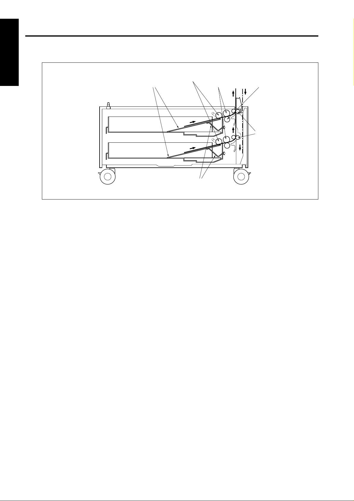
CENTRE CROSS-SECTIONAL DRAWING
1 OUTLINE2 UNIT EXPLANA TION3 DIS./ASSEMBLY
Paper lift-up plates
Feed rollers
Paper lowering levers
Double feed prevention
rollers/upper
Double feed prevention
roller/lower
Conveyance
rollers
1-2
Page 6
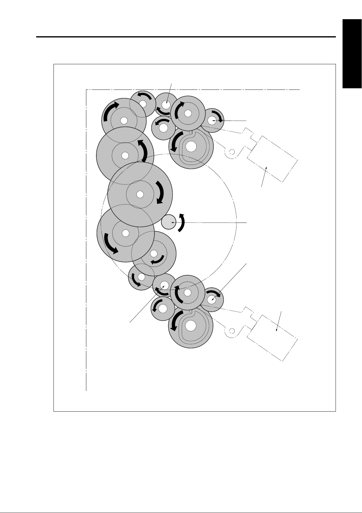
DRIVE SYSTEM DIAGRAM
Conveyance roller
DB-209
1 OUTLINE
Double feed prevention roller/upper
2 UNIT EXPLANA TION
1st paper feed SD (upper) (SD101)
Conveyance roller
DB drive motor (M101)
3 DIS./ASSEMBLY
Double feed prevention roller/lower
1st paper feed SD (lower) (SD102)
1-3
Page 7

2
UNIT EXPLANATION
1 OUTLINE
2 UNIT EXPLANA TION
3 DIS./ASSEMBLY
Page 8

PAPER FEED UNIT
DB-209
[1] Composition
Paper size indicator units
[2] Mechanisms
Mechanism Method
Paper feed Paper feed roller
Paper lifting Paper lift-up plate
Double feed Torque limiter
prevention
Tray loading Front loading
1st paper feed Paper feed SD
Feed roller
Jam processing Release of pressure on
double feed prevention roller
No paper detect Photosensor
Paper size detect Paper size indicator unit
Paper conveyance Roller conveyance
Conveyance drive Gears
1 OUTLINE2 UNIT EXPLANA TION3 DIS./ASSEMBL Y
Double feed prevention roller/upper
Double feed prevention roller/lower
Feed roller
Paper feed door
2-1
Page 9

DB-209
1 OUTLINE2 UNIT EXPLANA TION3 DIS./ASSEMBLY
[3] Paper feed and no paper detection
control
M100 CONT
SD101 CONT
SD102 CONT
DB SELECT1
DB SELECT2
MAIN BODY
24VDC
24VDC
PGND
PGND
5VDC
SGND
PS103
PS108
M100 CONT
SD101 DRIVE
SD102 DRIVE
PFUDB
24VDC
PGND
24VDC
24VDC
SGND
PS103
5VDC
SGND
PS108
5VDC
EM
M100
SD101
SD102
PS103
PS108
1. Operation
a. Paper feed operation timing (upper tray)
(1) 1st. sheet start
A specified time after start-button is turned ON
(2) 2nd. sheet start
A specified time after 1st. sheet SD101 is turned ON
(3) OFF timing
A specified time after SD101 is turned ON
b. Paper feed operation timing (lower tray)
(1) 1st. sheet start
A specified time after start-button is turned ON
(2) 2nd. sheet start
A specified time after 1st. sheet SD102 is turned ON
(3) OFF timing
A specified time after SD102 is turned ON
Paper feed is achieved by transmitting the drive of the
M100 (DB drive motor) to the upper and lower paper feed
rollers and to the feed rollers. When feed starts, SD101
(1st. paper feed SD (upper)) or SD102 (1st. paper feed SD
(lower)) raises and lowers the feed roller and contacts the
paper.
Drive of the M100, SD101 and SD102 is achieved by
PFUDB (PFU drive board)and controlled by the main
body.
No paper detection is achieved with PS103 (No paper
detect PS (upper)) and PS108 (No paper detect PS
(lower)) and controlled by the main body via the PFUDB.
c. No paper detection
If paper in the tray is used up, PS103 or PS 108 go [L]
and the no paper detection of each tray is sent to the
main body via the PFUDB.
2-2
Page 10

DB-209
DB DB-SELECT 1 DB-SELECT 0
DB-209 H L
DB-409 L H
No contact H H
Uncertain L L
Signal
2. Signals
a. Input signals
(1) PS103 (PS103 → PFUDB)
Upper tray paper/no paper detection signal
[H] :with paper
[L] :no paper
(2) PS108 (PS108 → PFUDB)
Lower tray paper/no paper detection signal
[H] :with paper
[L] :no paper
(3) M100 CONT (MAIN BODY → PFUDB)
M100 ON/OFF control signal from main body
(4) SD101 CONT (MAIN BODY → PFUDB)
SD101 ON/OFF control signal from main body
(5) SD102 CONT (MAIN BODY → PFUDB)
SD102 ON/OFF control signal from main body
b. Output signals
(1) M100 CONT (PFUDB → M100)
M100 drive control signal
[H] :M100 OFF
[L] :M100 ON
(2) M100 CLK (PFUDB → M100)
M100 revolution control board clock signal
(3) SD101 (PFUDB → SD101)
SD101 drive control signal
[H] :OFF
[L] :ON
(4) SD102 DRIVE (PFUDB → SD102)
SD102 drive control signal
[H] :OFF
[L] :ON
(5) PS103 (PFUDB → MAIN BODY)
Upper tray paper/no paper detection signal sent to
main body
1 OUTLINE2 UNIT EXPLANA TION3 DIS./ASSEMBL Y
(6) PS108 (PFUDB → MAIN BODY)
Lower tray paper/no paper detection signal sent to
main body
(7) DB SELECT (PFUDB → MAIN BODY)
DB Type identification signal sent to main body
2-3
Page 11

DB-209
1 OUTLINE2 UNIT EXPLANA TION3 DIS./ASSEMBLY
[4] Tray up and down control
24VDC
24VDC
PGND
PGND
5VDC
SGND
M101 CONT
M102 CONT
PS101
PS102
PS106
PS107
MAIN BODY PFUDB
M101 DRIVE
24VDC
SGND
PS101
5VDC
SGND
PS102
5VDC
M102 DRIVE
24VDC
SGND
PS106
5VDC
SGND
PS107
5VDC
M101
PS101
PS102
M102
PS106
PS107
2. Signals
a. Input signals
(1) PS101 (PS101 → PFUDB)
Upper tray detect signal
By turning ON with [L] showing, M101 raises the
paper in the upper tray.
(2) PS106 (PS106 → PFUDB)
Lower tray detect signal
By turning on with [L] showing, M102 raises the paper
in the lower tray.
(3) PS102 (PS102 → PFUDB)
Upper tray paper upper limit detect signal
When the upper tray paper is raised and arrives at the
upper limit position, the signal becomes [H] and
M101 is turned off.
(4) PS107 (PS107 → PFUDB)
Lower tray paper upper limit detect sensor
When the lower tray paper is raised and arrives at the
upper limit position, the signal becomes [H] and
M102 is turned off.
1. Operation
When the paper feed tray of each level is set, PS101
(Tray detect PS (upper)) and PS106 (Tray detect PS
(lower)) detect the tray, M101 (Paper feed motor 1)
and M102 (Paper feed motor 2) turn on and lift the
base plate in the tray. When the tray is lifted, PS102
(Upper limit detect PS (upper)) and PS 107 (Upper
limit detect PS (lower)) detect the paper upper limit
and turn ON, M101 and M102 turn off and the raising
of the tray is completed.
The down operation of the trays is performed
mechanically.
(5) M101 CONT (MAIN BODY → PFUDB)
M101 ON/OFF control signal from main body
(6) M102 CONT (MAIN BODY → PFUDB)
M102 ON/OFF control signal from main body
b. Output signals
(1) M101 DRIVE (PFUDB → M101)
M101 drive control signal
[L] :M101 ON
[H] :M101 OFF
(2) M102 DRIVE (PFUDB → M102)
M102 drive control signal
[L] :M102 ON
[H] :M102 OFF
(3) PS101 (PFUDB → MAIN BODY)
Upper tray detect signal sent to main body
(4) PS102 (PFUDB → MAIN BODY)
Upper tray paper upper limit detect signal sent to
main body
(5) PS106 (PFUDB → MAIN BODY)
Lower tray detect signal sent to main body
(6) PS107 (PFUDB → MAIN BODY)
Lower tray paper upper limit detect signal sent to
main body
2-4
Page 12

DB-209
[5] Paper size detection control
24VDC
24VDC
PGND
PGND
5VDC
SGND
SIZE D
SIZE C
SIZE B
SIZE A
MAIN BODY
Tray paper size is detected in the main body by a signal
sent from SDB1(size detection board1) and SDB2 (size
detection board2) via the PFUDB (PFU drive board).
1. Operation
a. Tray paper size detection
Paper size for either tray is set by SW1 above SDB1
and SDB2 and the PFUDB detects the switch signal
corresponding to the position of SW1.
The relation between switch signal and paper size is
as follows.
U SIZE D
U SIZE C
U SIZE B
U SIZE A
U SIZE SELECT
L SIZE D
L SIZE C
L SIZE B
L SIZE A
L SIZE SELECT
PFUDB
SW1
SDB1
SW1
SDB2
For U.S.A.
Paper size
(Label display
order)
11 x 17
A5R
A4
A4R
A3
F4
5.5 x 8.5
8.5 x 11
8.5 x 11R
8.5 x 14
For Europe
Paper size
(Label display
order)
11 x 17
B5
B4
A5R
A4
A4R
A3
F4
11
11R
1 OUTLINE2 UNIT EXPLANA TION3 DIS./ASSEMBL Y
Switch signal
SIZE A SIZE B SIZE C SIZE D
Switch signal
SIZE A SIZE B SIZE C SIZE D
2. Signals
a. Input signals
(1) U SIZE A - D (SDB1 → PFUDB)
Upper tray paper size detect signal
(2) U SIZE A - D (SDB2 → PFUDB)
Lower tray paper size detect signal
b. Output signal
(1) SIZE A - D (PFUDB → MAIN BODY)
Paper size detection signal sent to main body
2-5
Page 13

DB-209
1 OUTLINE2 UNIT EXPLANA TION3 DIS./ASSEMBLY
[6] Control of paper-level detection
[7] Jam detection control
NAIN BODY
SGND
5VDC
PFUDB
SGND
PS101
5VDC
SGND
PS106
5VDC
PS101
PS106
After the trays have been set in the machine, paper level is
detected by PS101 (tray detect sensor PS (upper)) and
PS106 (tray detect sensor PS (lower)).
As the paper level in tray runs low, the actuator at the rear
part of the tray gradually rotates as illustrated below. The
level is detected by the number of times the sensor goes
ON/OFF (the number of slits detected).
Rotation direction
(when moving up)
Tray detect
sensor
Slit 1
Slit 2
Actuator
MAIN BODY
5VDC
SGND
PS104
PS105
PFUDB
SGND
PS104
5VDC
SGND
PS105
5VDC
1. Operation
The ADU jam detect control is performed by the main
body when it has judged the changes in the PS104
(jam detect PS1) and PS105 (Jam detect PS2)
detection signals. If the ON detection signal of each
sensor does not change after a specified time, it is
judged that there is a paper jam.
2. Signals
a. Input signals
(1) PS104 (PS104 → PFUDB)
Turns on when [H] is showing, and notifies the main
body of the presence or absence of paper in the
upper part of the DB.
(2) PS105 (PS105→PFUDB)
Turns on when [H] is showing, and notifies the main
body of the presence or absence of paper in the
lower part of the DB.
PS104
PS105
1. Operation
a. Detection of paper level in tray
The following shows the relation between the paper
level and the number of slit detections by the sensor
(PS101 or PS106).
0 slits : Full
1 slit : Medium
2 slits : Low
b. Output signals
(1) PS104 (PFUDB→MAIN BODY)
PS104 detect signal sent to main body
(2) PS 105 (PFUDB→MAIN BODY)
PS105 detect signal sent to main body
2-6
Page 14

3
DISASSEMBLY/ASSEMBLY
1 OUTLINE
2 UNIT EXPLANA TION
3 DIS./ASSEMBLY
Page 15

1 OUTLINE2 UNIT EXPLANA TION3 DIS./ASSEMBLY
This section explains how to disassemble and reassemble the
machine.
Observe the following precautions when performing disassembly
and assembly work.
1. Be sure to unplug the power cord before working on the
machine.
2. Perform all reassembly work by reversing the order in which the
component was disassembled, unless otherwise specified.
3. Do not lose small parts (screws, etc.) or insert them in the
wrong place.
4. Install all parts completely before operating the machine.
5. Do not loosen the screws indicated as disallowed for removal.
Page 16

DISASSEMBLY/ASSEMBLY
DB-209
Caution: Make sure the power plug is taken
out of the socket.
[1] Removing and reinstalling paper
feed tray
(1) Pull out the paper feed tray and take out the 2 set
screws on the right hand side.
(2) Remove the paper tray from the guide rails.
Set screws
Paper feed trays
Guide rails
[2] Removing and reinstalling the
paper feed unit
(1) Remove the paper feed tray and the tray cover.
Tray cover
(2) Opening the paper feed door, take out the 3 set
screws and remove the each paper size indicator
units.
1 OUTLINE
2 UNIT EXPLANATION3 DIS./ASSEMBLY
(3) Install by reversing the removal procedure.
Paper size
indicator units
(3) Remove the 3 set screws and remove the cover.
Cover
Set screws
(4) Remove the paper feed unit connector.
Paper feed door
Set screws
3-1
Page 17

DB-209
(5) Remove the 2 screws indicated by the engraved
1 OUTLINE2 UNIT EXPLANATION
3 DIS./ASSEMBLY
arrows and remove by drawing the paper feed unit
forward.
Paper feed units
Set screws
(6) Install by reversing the removal procedure.
Caution: Immediately after installing the paper feed
unit, as the swing gear and the paper feed
solenoid are not in the correct position, it
sometimes happens that paper is not fed.
For this reason, always make a copy to
confirm that operation is normal.
[3]
Replacing of the feed roller rubber
and double feed prevention rubber/
upper
(1) Remove the paper feed unit.
(2) Remove the fixing rings and bearings.
(3) While withdrawing the paper feed shaft, remove the
double feed prevention roller/upper from the paper
feed roller unit.
Double feed prevention roller/upper
Paper feed roller unit
Fixing rings
Feed shaft
(4) Removing the fixing ring and remove the feed roller
by withdrawing the guide shaft in the direction
shown by the arrow.
(5) Remove the feed rubber from the feed roller.
(6) Remove the double feed prevention rubber/upper
from the swivel roller.
Feed rubber
Guide shaft
Fixing
ring
Feed roller
Feed shaft
Swivel roller
Double feed
prevention
rubber/upper
Paint mark
(7) Install by reversing the removal procedure.
Caution: Pay attention to the direction in which you
install each roller rubber. Install so that the
swing-gear shaft enters the paper feed
roller unit.
3-2
Page 18

DB-209
[4] Replacing the double feed
prevention rubber/lower
(1) Remove the paper feed unit.
(2) Remove the set screw.
(3) Pushing the knobs on either side of the double feed
prevention unit, then remove by drawing it forward.
Double feed
prevention unit
Set screw
(4) While pushing the projection of the lever click shaft,
withdraw it and remove the double feed prevention
roller.
1 OUTLINE
2 UNIT EXPLANATION3 DIS./ASSEMBLY
Double feed prevention
Paint mark
(5) Remove the double feed prevention rubber/lower
from the double feed prevention roller.
(6) Install by reversing the removal procedure.
Caution : Pay attention to the direction in which
rubber/lower
Double feed prevention
roller
Lever click shaft
you install each roller rubber.
When installing the double-feed
prevention unit into the main body, be
sure to align it with the center of the
mark engraved on the main-body
plate.
3-3
 Loading...