

Page 1

3
DISASSEMBLY/ASSEMBLY
1 OUTLINE
2 UNIT EXPLANATION
3 DIS./ASSEMBLY
Page 2

2
1 OUTLINE2 UNIT EXPLANATION3 DIS./ASSEMBLY
This section explains how to disassemble and reassemble the machine.
When disassembling and reassembling the machine, follow the
precautions given below.
1. Be sure the power cord has been unplugged from the wall outlet.
2. The disassembled parts must be reassembled following the
disassembly procedure in reverse unless otherwise specified.
3. Care should be taken not to lose small parts. Care should also be
taken not to install small parts in wrong places.
4. Do not operate the machine before installing all the disassembled
parts completely.
5. Removal of some screws is prohibited in this section. Never loosen
them.
Page 3

EXTERNAL SECTION
EXTERNAL SECTION
[1] Replacing the ozone filter
Caution: Be sure that the power cord has
been unplugged from the outlet.
a. Procedure
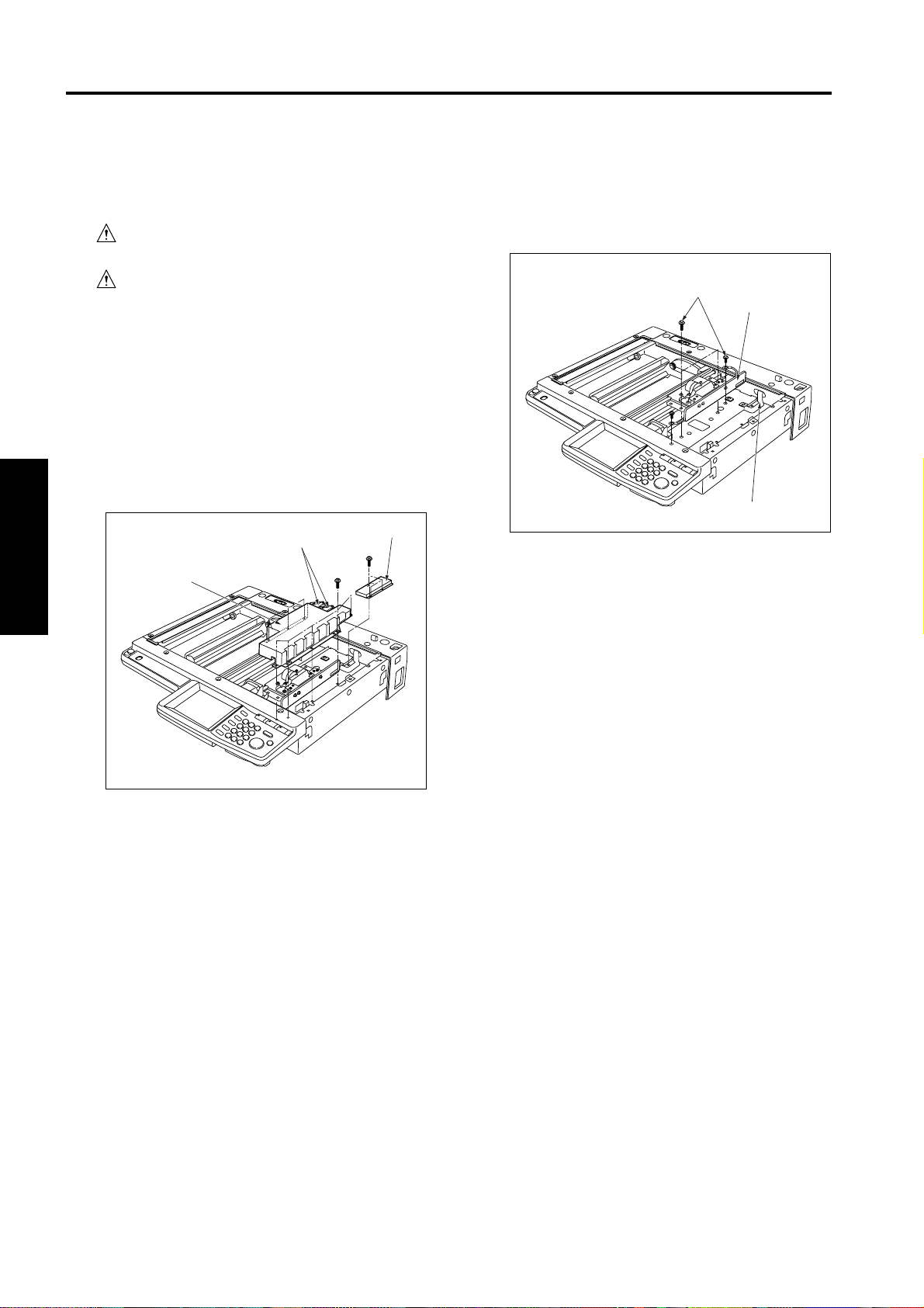
(1) Remove the five set screws, and remove the read
right cover.
Set screws
Read right
cover
1 OUTLINE
2 UNIT EXPLANATION
3 DIS./ASSEMBLY
(2) Remove the ozone filter.
Ozone filter
(3) Reinstall the above parts following the removal
steps in reverse.
3-A-1
Page 4
DRIVE SECTION
DRIVE SECTION
[1]
Removing and Reinstalling the motor
units (main, paper feed, developing)
Caution: Be sure that the power cord has
been unplugged from the outlet.
Caution: Be sure to remove the drum unit
from the main body before removing
or reinstalling the main motor unit. If
the drum unit is in place at this time,
the drum will rotate when you install
or remove the drum rotating plate,
resulting in possible damage to the
cleaning blade.
a. Procedure
(1) Remove the developing unit and drum unit from the
main body.
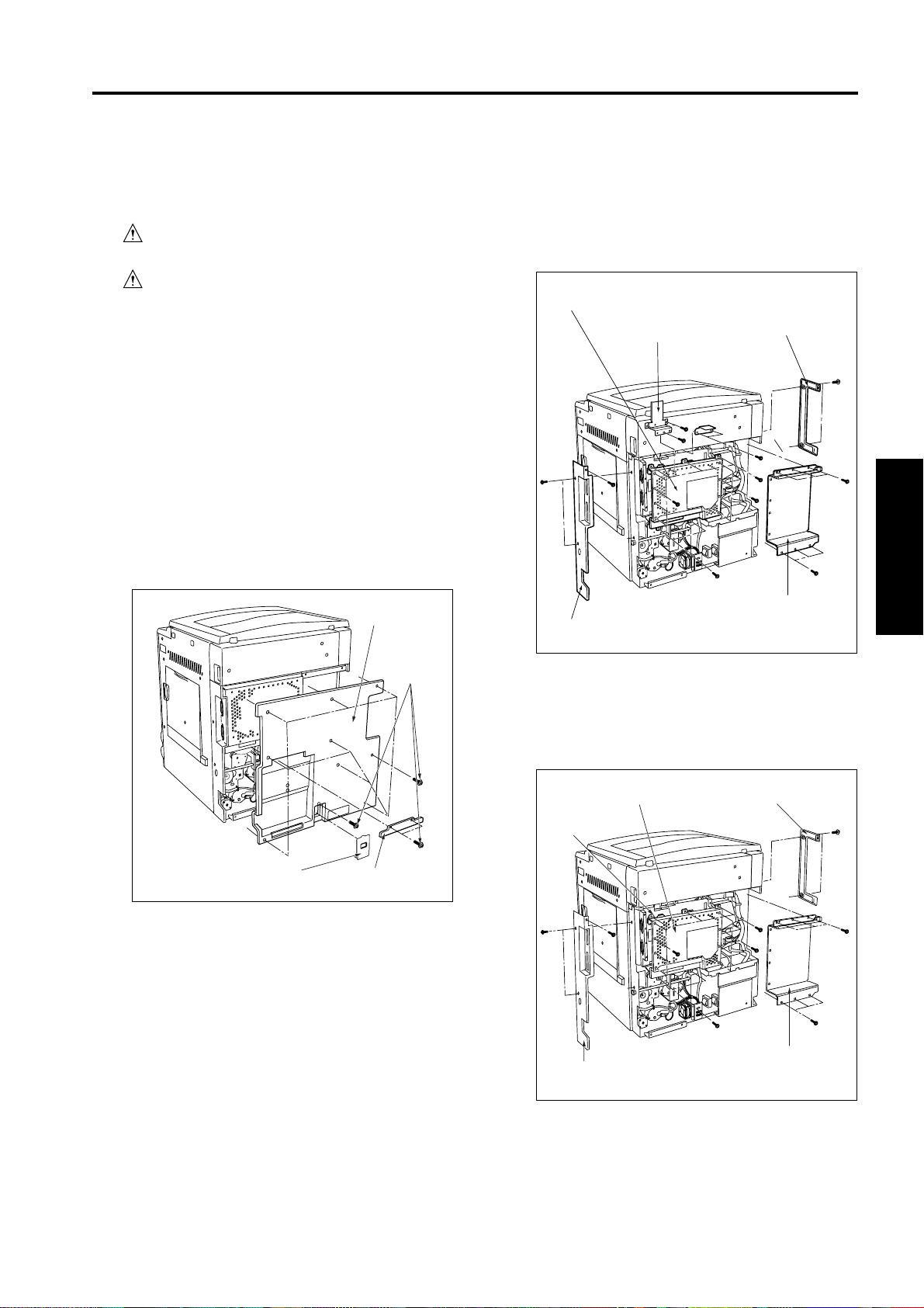
(2) Remove the 2 set screws, and remove the cord
cover A. Then remove the cord cover B.
(3) Remove the 9 set screws, and remove the rear
cover.
Rear cover
(4) Remove the 2 set screws holding the left and right
rear covers in place (2 screws each), and remove
the covers.
(5) Remove the 3 set screws, and remove the wire-
bundle guide plate.
Board cover A
Wire bundle
guide plate
Rear right cover
Rear left cover
Board cover D
1 OUTLINE
2 UNIT EXPLANATION
3 DIS./ASSEMBLY
Cord cover B
Set screws
Cord cover A
(6) Remove the 16 set screws, and remove the board
cover D.
(7) Remove the 13 set screws, and remove the board
cover A.
Board cover A
Wire bundle
guide plate
Rear right cover
Rear left cover
Board cover D
3-B-1
Page 5
2
DRIVE SECTION
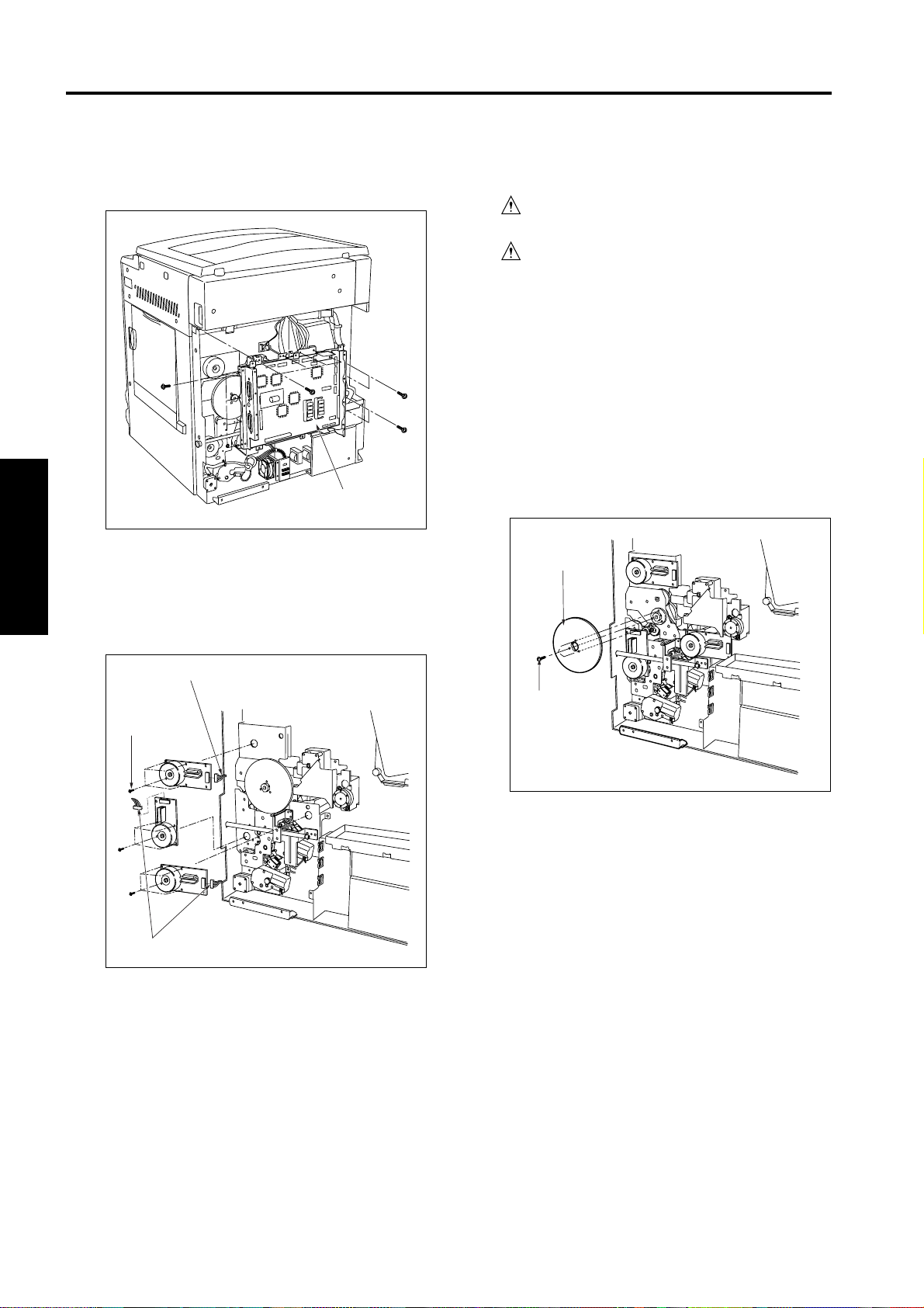
(8) Remove the various wiring connectors from the
1 OUTLINE2 UNIT EXPLANATION3 DIS./ASSEMBLY
overall control board.
Overall control board
unit
[2] Replacing the registration clutch
Caution: Be sure that the power cord has
been unplugged from the outlet.
Caution: Be sure to remove the drum unit
from the main body before carry out
the following procedure. If the drum
unit is in place at this time, the drum
will rotate when you install or
remove the drum rotating plate,
resulting in possible damage to the
cleaning blade.
a. Procedure
(1) Remove the rear panel and the system control
board unit.
(2) Remove the 3 set screws, and remove the drum
rotating plate.
(9) Remove the 12 set screws, and remove the overall
control board unit.
(10) Disconnect the connectors from each motor unit.
(11) Remove the 4 set screws, then remove each motor
unit.
Connector
Set screws
Connectors
(12) Reinstall in the opposite sequence to removal.
Caution: Be careful to avoid damaging the cable
ribbon connected to the overall control
board.
Drum rotating
plate
Set screws
3-B-2
Page 6
DRIVE SECTION
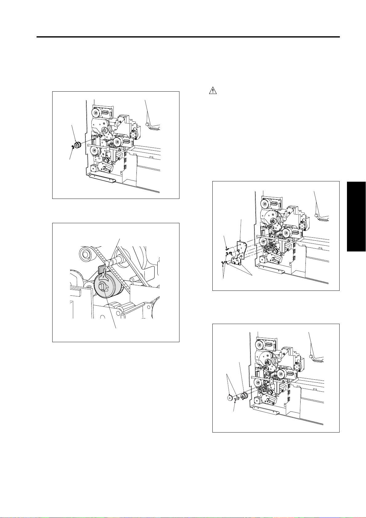
(3) Remove the clutch connector.
(4) Remove the E-ring. Pull the registration clutch
toward you and rotate it to remove.
Registration
clutch
E-ring
(5) Reinstall in the opposite sequence to removal.
Turn-prevention groove
[3] Replacing the loop clutch
Caution: Be sure that the power cord has
been unplugged from the outlet.
a. Procedure
(1) Remove the rear panel and the system control
board unit.
(2) Remove the wire bundle from the clamp on the
conveyance drive panel.
(3) Remove the 2 E-rings and 3 set screws, and
remove the conveyance drive panel. (Do not
remove the rotation prevention screws on the
clutch.
Conveyance
drive panel
Set screw
1 OUTLINE
2 UNIT EXPLANATION
3 DIS./ASSEMBLY
Registration clutch
Caution: When installing the registration clutch, be
sure that the clutch's turn-prevention
groove is installed correctly.
E-rings
Bearings
(4) Remove the E-ring and gear, then remove the gear
at the front, and then remove the clutch.
Loop clutch
Gears
E-ring
(5) Reinstall in the opposite sequence to removal.
3-B-3
Page 7
READ SECTION
READ SECTION
[1] Screws that must not be removed
Caution: The paint-locked screws must not
be removed. Be sure that you do not
remove these screws.
Screws that must not be removed
Screws that must not be
Screws that
must not be
removed
Screws that must not be removed
removed
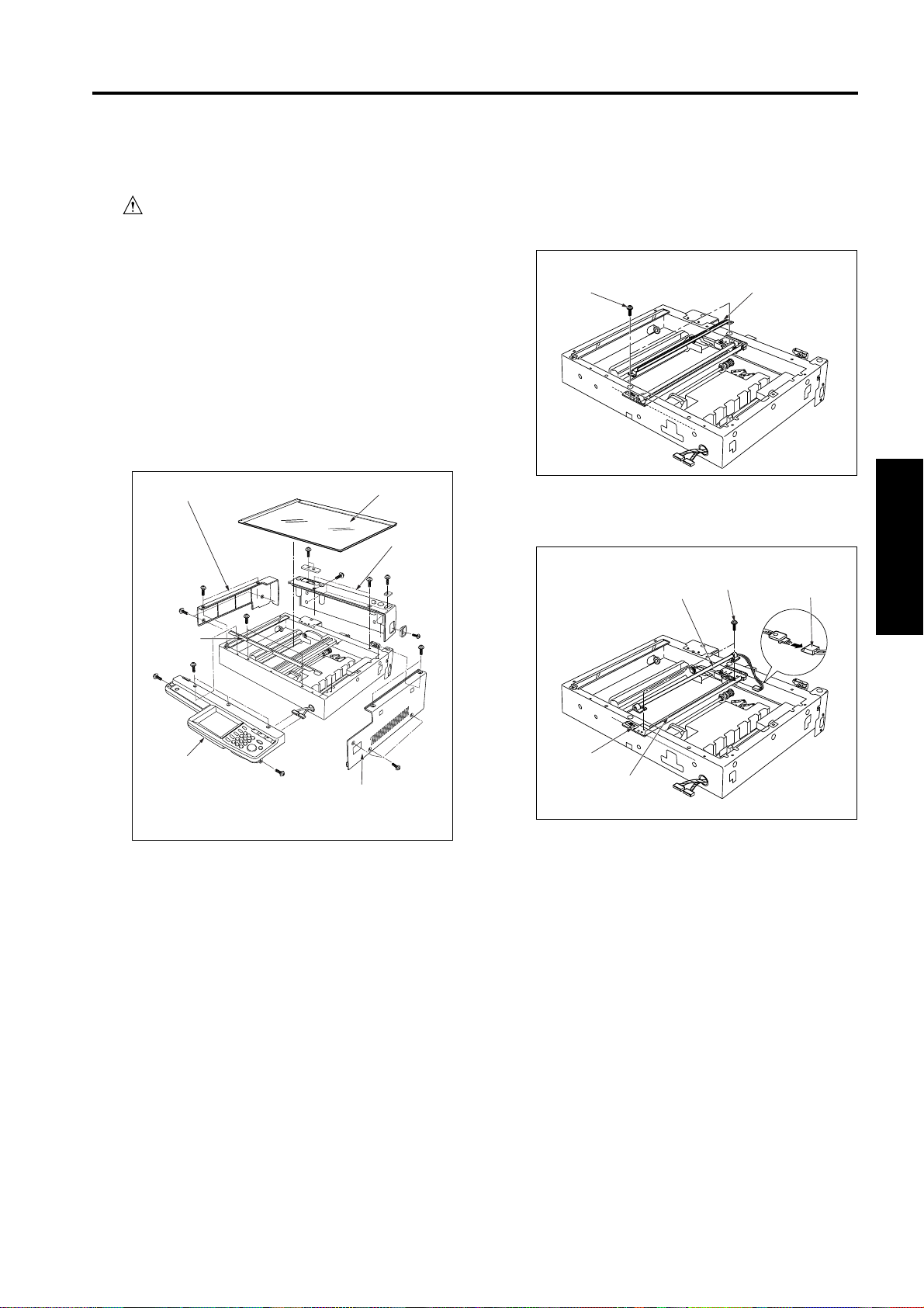
[2] Removing the original glass
Caution: The white color reference plate on
the rear of the original glass must be
kept clean. If dirt gets on the board,
clean the board using a clean cloth.
a. Procedure
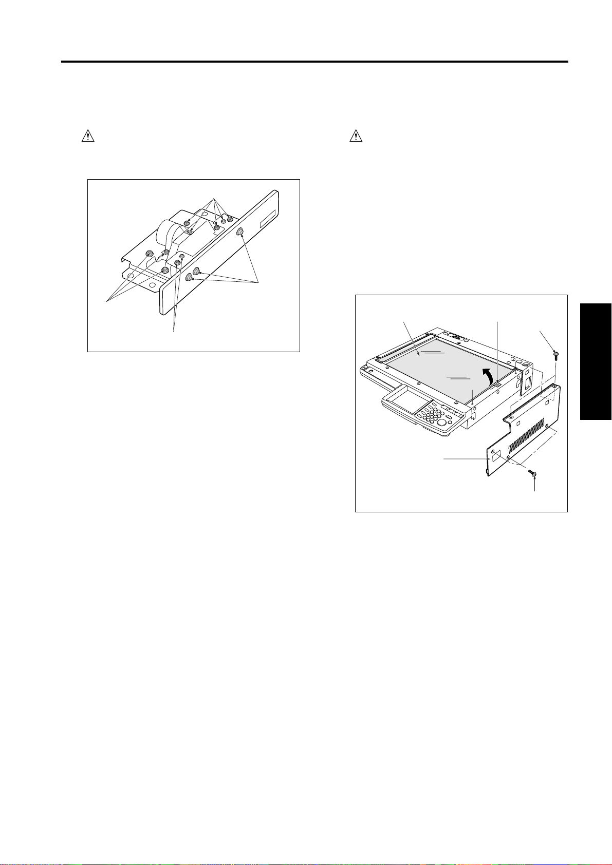
(1) Remove the platen cover or the RADF.
(2) Remove the 5 set screws, and remove the read
right cover.
(3) Loosen the set screw and slide the glass holding
plate toward the outer exterior.
(4) Raise the original glass and slide it off.
Original glass
Glass holding plate
Set screws
1 OUTLINE
2 UNIT EXPLANATION
3 DIS./ASSEMBLY
Read
right cover
Set screws
(5) Reinstall in the opposite sequence to removal.
Caution: Be sure that the original glass is pushed
flush left against the glass holding plate
when fastening into place.
3-C-1
Page 8
2
READ SECTION
1 OUTLINE2 UNIT EXPLANATION3 DIS./ASSEMBLY
[3] Removing and Reinstalling the
CCD unit
Caution: Be sure that the power cord has
been unplugged from the outlet.
(5) Remove the cable ribbon from the CCD unit board.
(6) Remove the 2 set screws, and remove the CCD
unit.
Caution: Be sure to perform image adjustment
after installing the CCD unit. (Refer
to the “Adjustment” section.)
a. Procedure
(1) Remove the original glass.
(2) Remove the 2 set screws, and remove the photo-
sensor.
(3) Remove the 8 set screws, and remove the lens
shield cover.
(4) Remove the 3 set screws, and remove the cable
ribbon cover.
Photosensors
Lens shield cover
Cable ribbon
cover
Set screws
(7) Reinstall in the opposite sequence to removal.
Caution: Be careful to avoid damage to the cable
ribbon when removing it. When reinstalling
it, be sure that it is securely in place.
CCD unit
board
Cable ribbon
3-C-2
Page 9
READ SECTION
[4] Replacing the exposure lamp
Caution: Be sure that the power cord has
been unplugged from the outlet.
Do not touch the exposure lamp's
lamp area with bare hands.
Caution: Be sure to clean original glass before
reinstalling it.
a. Procedure
(1) Remove the read right cover and the original glass.
(2) Remove the operation panel, the read left cover,
and the read rear cover.
(3) Remove the 2 set screws, and remove the read
front cover.
(3) Read left cover
(6) Read
front cover
(2) Original glass
(4) Read
rear
cover
(4) Shift the exposure unit to the cutout location at the
center of the main body frame.
(5) Remove the 2 set screws (through the holes in the
frame), and remove the auxiliary reflecting mirror.
Auxiliary
reflecting mirrorSet screws
(6) Remove the 1 connector and 2 set screws. Tilt and
remove the exposure lamp.
Set screws
Exposure lamp
Connector
1 OUTLINE
2 UNIT EXPLANATION
3 DIS./ASSEMBLY
(5) Operation panel
* Remove above parts in
order of numbers.
(1) Read right cover
Cutout
Exposure unit
(7) Reinstall in the opposite sequence to removal.
Caution: Be careful when reinstalling the original
glass. To install: push the glass against
the left rear of the readout rear exterior,
then hold the readout front cover against
with glass hold plate.
And further, hold the glass plate, while
pressing the cut portion of the read left
cover.
3-C-3
Page 10
READ SECTION
2
1 OUTLINE2 UNIT EXPLANATION3 DIS./ASSEMBLY
[5] Removing and Reinstalling the
exposure unit
Caution: Be sure that the power cord has
been unplugged from the outlet.
Caution: Be sure to the use optics positioning jig
when reinstalling the exposure unit.
Be sure to clean the original glass before
reinstalling it (to prevent degradation of
image quality).
a. Removal procedure
(1) Remove the read right cover and the original glass.
(2) Remove the operation panel, read left cover, and
read rear cover.
(3) Remove the 2 set screws, and remove the read
front cover.
(4) Shift the exposure unit to the cutout location at the
center of the main body frame.
(5) The exposure unit is fixed in place by set screws
fastened to the front and rear exposure unit mount
fittings (1 screw in each fitting). Remove the 2
screws.
b. Installation procedure
(1) Fit the exposure unit into the main body.
(2) Insert the front exposure unit mount fitting and rear
exposure unit mount fitting into the corresponding
slits in the exposure unit.
(3) Shift the V mirror unit to the exit side. Through the
front, insert the two optics positioning jigs so that
they are at the installation location for the exposure
unit. Pass the jig through the V mirror unit to fasten
it in place.
Position the exposure unit by pushing it against the
frame on the right side of the unit.
Remove cable clamp.
Exposure unit
V mirror unit
Set screws
Exposure unit
Exposure unit
mount fittings
(6) Tilt and slide the exposure unit to remove it from
the frame.
(7) Disconnect the exposure lamp connector.
Optics
positioning
jigs
(4) Fasten the front and rear exposure unit mount
fittings into place (1 screw in each fitting).
(5) Remove the optics positioning jigs.
(6) Finish installation by reversing the sequence of the
removal procedure.
Exposure unit mount
fitting (front)
Exposure unit mount
fitting (rear)
3-C-4
Page 11
READ SECTION
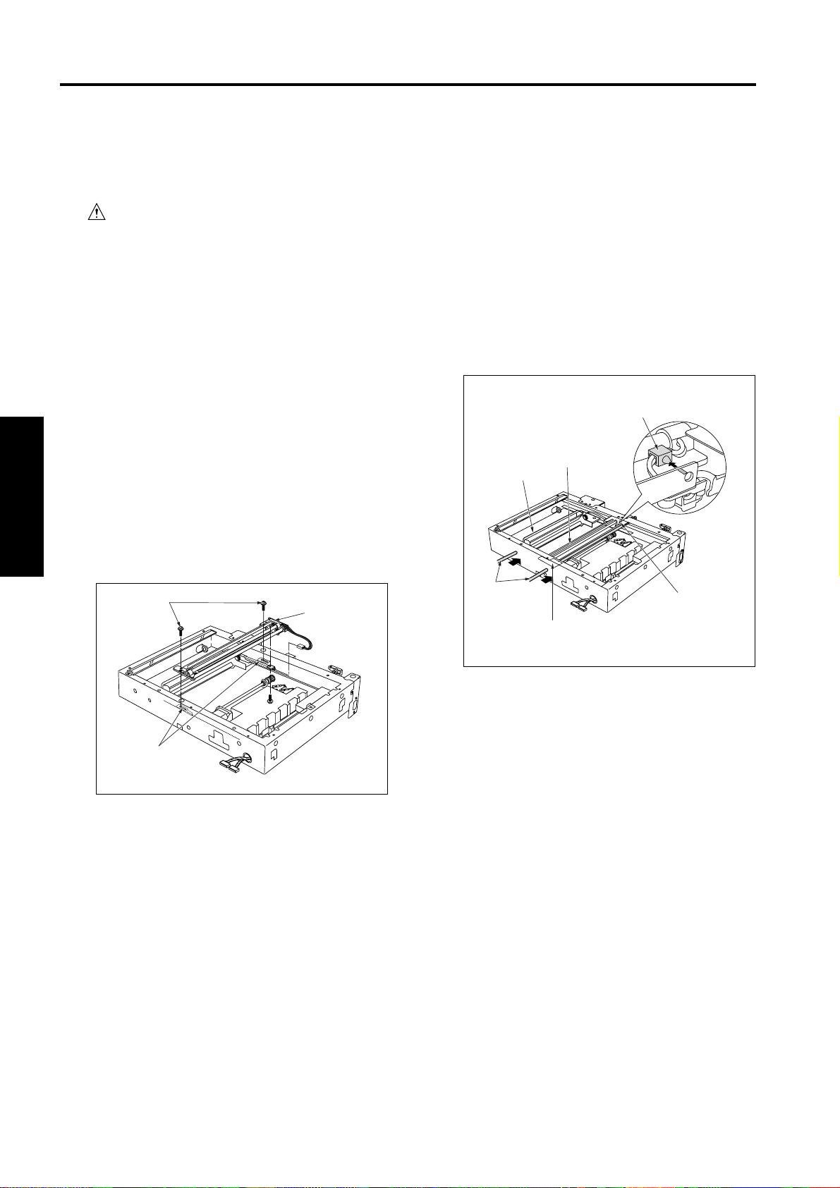
[6] Removing and Reinstalling the
optics drive motor
a. Procedure
(1) Remove the original glass.
(2) Remove the 3 set screws, and remove the optical
motor.
Set screws
Optical motor
Belt
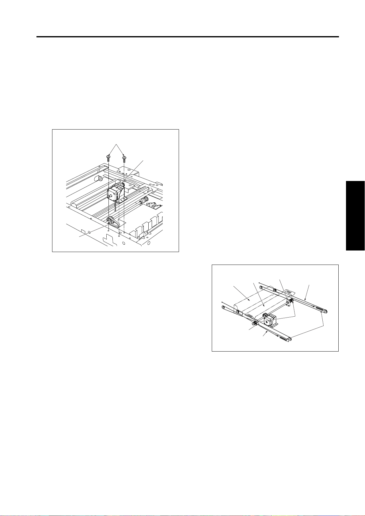
[7] Removing the optics wire
Caution: When removing or reinstalling optics
wires, be sure to the use optics positioning
jig.
Be sure to perform image adjustment after
replacing or reinstalling the wire. (For
details, refer to “Adjustment section”.)
a. Procedure
(1) Unfasten and remove all externals from the read
unit.
(2) Shift the V mirror unit to the left side. Through the
front, insert the optics positioning jig so that it is at
the V mirror attachment location. Pass the jig
through the V mirror unit to fasten the it in place.
(3) Remove the exposure unit.
(4) Detach the springs from the ends of the front and
rear optics wires (1 spring on each wire), and
remove the wires.
(5) Remove the set screws holding the two drive pulley
bearings in place (two screws on each pulley), and
remove the bearings.
(6) Remove the front and rear optics wires from the
drive pulleys.
1 OUTLINE
2 UNIT EXPLANATION
3 DIS./ASSEMBLY
(3) When reinstalling, apply light tension to the belt
while fastening the motor into place.
V mirror
unit
Optics unit
Bearing
Optics wire (front)
Bearing
Optics wire (rear)
Drive
pulleys
Springs
3-C-5
Page 12

READ SECTION
2
1 OUTLINE2 UNIT EXPLANATION3 DIS./ASSEMBLY
[8] Installing the optics wire
Caution 1: When winding wire around pulleys, be
sure that the winds are close. Be
careful to avoid overlap.
Caution 2: When changing the wire, be sure to
use the optics positioning jigs.
Caution 3: Be sure to perform image adjustment after
installing the CCD unit. (Refer to the
“Adjustment” section.)
a. Procedure
(1) Fit the metal ball (midway along each optics wire)
into the mount opening on the drive pulley. Starting
from this position, wind 6 times around the outside
and 5 times around the inside.
• After winding the wires, fasten them in place (with
tape, etc.) so that they cannot come off.
• Use the "F" exposure unit mount fitting (the fitting
with the "F" printed on it) at the front, and use the
"R" fitting at the rear.
• The end with the metal ball at the tip winds around
the inside of the pulley shaft.
• Wind so that the two ends of the wire come off the
top of the pulley.
(2) On the metal ball side, pass the optics wire so that
it passes under the V mirror unit, through the left
side pulley, and through the inside pulley on the V
mirror unit. Hook the end of the wire onto the cutout
on the frame.
(3) On the round-end side, pass the wire so that it
passes through the right side pulley, passes over
the pulley on the outside of the V mirror unit, and
passes under the V mirror unit. Fasten the end to
the right side frame with a the spring.
(4) Fasten the drive pulley bearings into place with the
attachment screws (2 screws each).
(5) Using the optics positioning jigs to install the
exposure unit.
(6) Remove the jigs.
(7) Slide the exposure unit two or three times to make
sure that it works correctly.
Pulley
Metal ball
V mirror unit
To metal
ball
Tape
(Rear)
5 winds
6 winds
6 winds 5 winds
Front
Rear
(Front)
Tape
Drive
pulleys
To metal
ball
Exposure
Pulley
V mirror unit
Optics positioning jigs
unit
Remove cable clamp.
3-C-6
Page 13

WRITE UNIT
WRITE UNIT
[1] Removing and Reinstalling the
write unit
Warning:
(1) Never supply power while the write unit is
out of its proper installed position.
(2) Do not open the cover of the write unit
while power is being supplied. Shining of
the laser beam on the eye may cause
blindness.
(3) After turning the main power switch OFF,
wait at least two minutes before removing
the write unit.
Caution: Be sure that the power cord has
been unplugged from the outlet.
Caution: When removing the write unit, take care to
avoid touching with the write mirror and
the dust proof glass. (Touching these
areas may leave scratches and smudges.)
a. Procedure
(1) Open the front door and remove the drum unit and
the developing unit.
(2) Remove the exit tray, open the ADU door, and
remove the front door and the main body front cover.
Remove the side rear cover, the main-body upper
cover, and the main-body auxiliary cover.
(3) Remove the write cleaning knob from the dust
proof glass cleaning rod and then puch the rod to
inside of main body.
Cleaning knob
(4) Remove the 11 set screws, and remove the write
cover.
Set screws
Write cover
1 OUTLINE
2 UNIT EXPLANATION
3 DIS./ASSEMBLY
(5) Main body auxiliary cover
(2) Main body front cover
(3) Side rear cover
(4) Main body upper cover
*Remove above parts in order of numbers.
(1) Front door
3-D-1
Page 14
WRITE UNIT
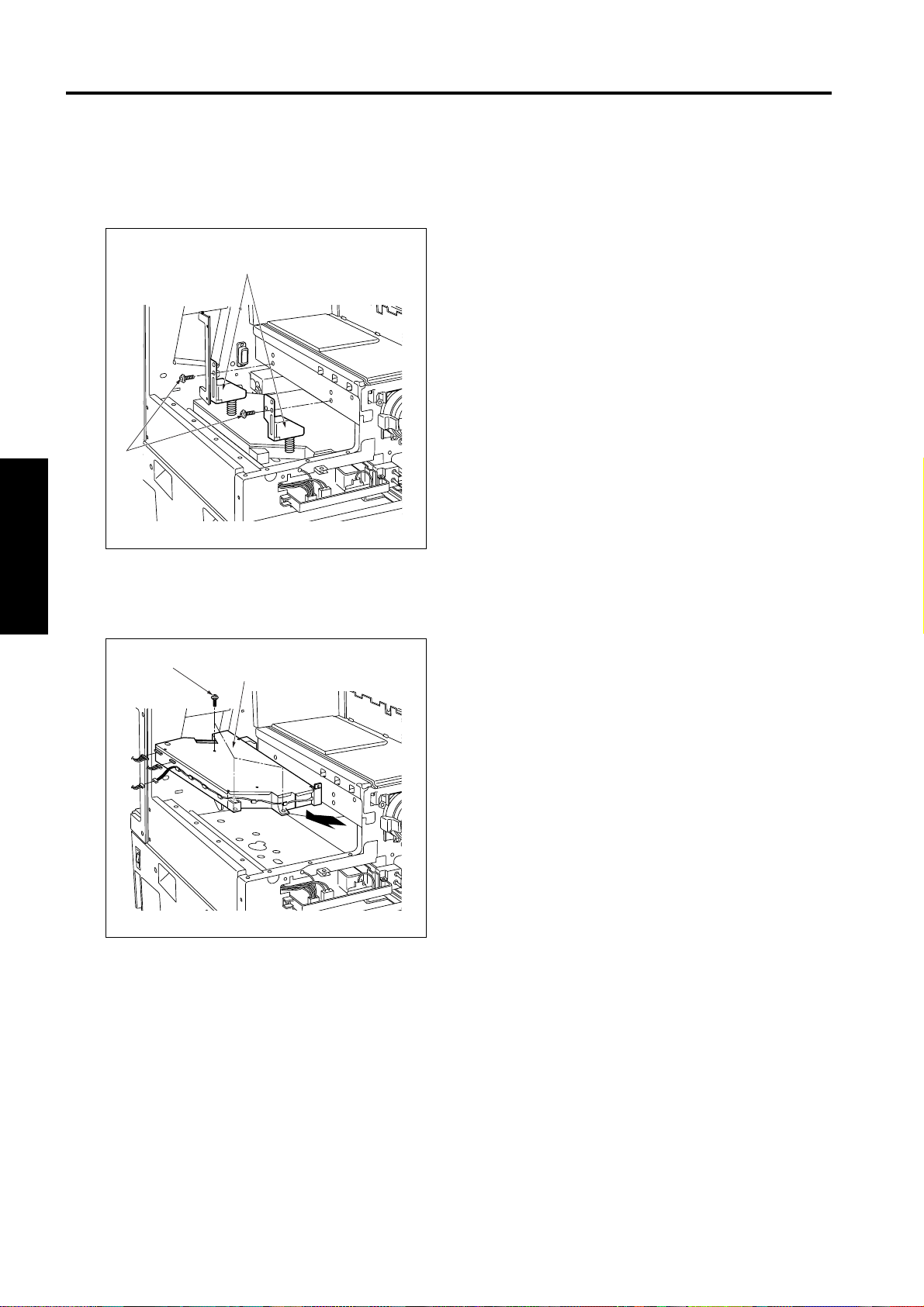
(5) Remove the two write unit mount pieces (each is
1 OUTLINE2 UNIT EXPLANATION3 DIS./ASSEMBLY
held in place by set screw).
2
Write unit mount pieces
Set
screws
(6) Disconnect the 3 connectors.
(7) Remove the 3 set screws, and remove the write
unit by pulling it to the left.
Set screws
Write unit
(8) Reinstall in the opposite sequence to removal.
3-D-2
Page 15
DRUM UNIT
DRUM UNIT
[1] Removing and Reinstalling the
drum unit
Caution: Be sure that the power cord has
been unplugged from the outlet.
Caution 1: After removing the drum unit, close the
drum cover and store the unit in a dark
place.
Caution 2: During removal and reinstallation work,
never rotate the drum in the wrong
direction (in the direction opposite to
the direction it moves during normal
copying). Rotating the drum in the
reverse direction may cause scratches
to the cleaning blade.
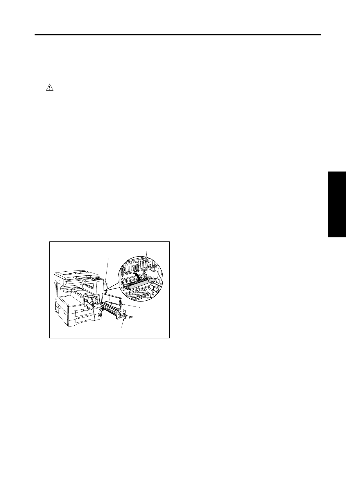
a. Procedure
(1) Open the front door, loosen the set screw, and
gently pull the developing unit out toward you.
(2) Open the ADU door, and open the conveyance
unit.
(3) Loosen the set screw, and gently pull the drum unit
out toward you until it stops. Then tilt it slightly and
remove it.
Conveyance unit
ADU door
[2] Removing and Reinstalling the
drum
Caution 1: Take care to avoid scratching the
drum's light sensitive areas and the
cleaning blade. Do not touch these
areas with bare hands.
Caution 2: When removing or installing, never
allow the drum to bump against the
plate-metal part of the cleaning blade.
Caution 3: If you are going to leave the drum
outside of the drum unit, be sure to
close the drum cover and place in a
dark location.
Caution 4: Before installing the drum and cleaning
blade (regardless of whether new or
used), be sure to coat these with
setting powder. Apply the powder
around the entire drum, and on both
sides of the blade.
Caution 5: If you have coated setting powder onto
the drum: Before installing the drum
unit back into the main body, use an
alcohol-soaked cloth to remove stray
powder from the sensor surface on the
toner control sensor board. This is
necessary to ensure that accurate
toner density readings are obtained.
1 OUTLINE
2 UNIT EXPLANATION
3 DIS./ASSEMBLY
Front door
Drum unit
(4) Reinstall in the opposite sequence to removal.
Caution 6: Be sure that the drum is oriented
correctly before installing it. The
convex end (bulging end) should be
facing the rear.
Caution 7: If you are installing a new drum,
remember to reset the drum counter.
(Use mode 36, counter clear).
3-E-1
Page 16

DRUM UNIT
2
a. Removing procedure
1 OUTLINE2 UNIT EXPLANATION3 DIS./ASSEMBLY
(1) Remove the drum unit from the main body.
(2) Set the unit so the drum is to the top.
(3) Remove the 2 set screws and remove the charging
corona unit.
Charging corona unit
Set screw
(4) Remove the stopper ring, and pull out the drum
shaft.
Drum shaft
Stopper ring
Clearning rod
(6) Remove the 2 semicircular seal blocks (one on
each end of the drum).
(7) To remove the drum, push it back toward the rear
and lift it up and out from the front.
Seal blocks
Set screw
Drum bearing
Stopper
fitting
b. Installing procedure
Caution: Be sure that the toner collection sheet
makes contact with the entire span of the
drum, with no gaps.
(1) Coat the entire surface of the drum with setting
powder.
(2) Fit the convex end of the drum into the rear side of
the unit, then set the drum down into the unit.
Reattach the two seal blocks (one at each end of
the drum).
(5) Remove the 2 set screws holding the drum bearing
in place, and remove the bearing.
Seal block (rear)
Seal block (front)
Drum
(3) Reattach the drum bearing. Fasten it into place with
the 2 set screws.
(4) Insert the drum shaft and reattach the stopper.
3-E-2
Page 17

DRUM UNIT
(5) Using the jig included on the drum unit cover, rotate
the drum clockwise and confirm that there are no
gaps in the setting powder coat, and that the toner
collection sheet and cleaning blade are smooth,
etc.
Jig
(6) Install the charging corona unit. Fasten it into place
with 2 set screws.
[3] Removing and Reinstalling the
separation claw
Caution 1: While removing or installing the claw,
be careful to avoid damage to the
drum.
Caution 2: When installing the claw, be sure that it
is correctly oriented and positioned.
Caution 3: Do not touch the cleaning blade or the
drum's light sensitive areas with bare
hands.
a. Procedure
(1) Remove the drum unit from the main body.
(2) Remove the drum from the drum unit.
(3) Disconnect the relay connector.
(4) Remove the separation rock spring.
(5) Remove the 2 positioning screws and the 2 collars,
and then remove the separation claw unit.
Separation rock spring
Positioning screws
Relay Connector
1 OUTLINE
2 UNIT EXPLANATION
3 DIS./ASSEMBLY
Collars
Separation claw unit
(6) Press down on the separation fulcrum shaft and
remove the 2 separation claws.
Separation claw
Separation
fulcrum shaft
(7) Reinstall in the opposite sequence to removal.
3-E-3
Page 18

CORONA UNIT SECTION
CORONA UNIT SECTION
[1] Removing and Reinstalling the
charging corona unit
Caution: Be sure that the power cord has
been unplugged from the outlet.
a. Procedure
(1) Remove the drum unit from the main body.
(2) Remove the cleaning rod's shaft stopper fitting, and
pull out the cleaning rod.
(3) Disconnect the connector from the drum unit.
(4) Remove the 2 set screws, and remove the charging
corona unit by pulling it out from the rear.
Stopper
fitting
Charging
Connector
Cleaning rod
corona unit
[2] Removing and Reinstalling the
charge control plate
Caution: When reinstalling, be sure to set the
charge control plate so that the
spring held end is toward the front
of the charging corona unit.
a. Procedure
(1) Remove the drum unit from the main body.
(2) Remove the charging corona unit. Move the
charging cleaning block to its home position (at the
right side).
(3) Remove the 2 charge control springs, and remove
the charge control plate.
(4) To clean, use: Tap lightly with a cloth soaked in
drum cleaner, then use a blower brush to remove
remaining debris.
Charge control plate
Charge control
springs
1 OUTLINE
2 UNIT EXPLANATION
3 DIS./ASSEMBLY
(5) Reinstall in the opposite sequence to removal.
(5) Reinstall in the opposite sequence to removal.
3-F-1
Page 19

CORONA UNIT SECTION
2
1 OUTLINE2 UNIT EXPLANATION3 DIS./ASSEMBLY
[3] Replacing the charging wire
a. Procedure
(1) Remove the drum unit from the main body.
(2) Remove the charging corona unit. Move the
charging cleaning block to its home position (at the
right side).
(3) Remove the charge control plate.
(4) Remove the 2 charging covers (charging rear
cover, and charging front cover).
(5) Remove the spring, and remove the charging wire.
Charging rear cover
Charging wire
Charging front cover
Spring
[4] Removing and Reinstalling the
transfer and separation corona unit
Caution: Be sure that the power cord has
been unplugged from the outlet.
a. Procedure
(1) Open the ADU door.
(2) Pull the conveyance unit toward you to open.
(3) The transfer/separation corona unit is held in place
by two catches, one at each end. Press in on these
catches and remove the unit.
Transfer/Separation
corona unit
(6) To install the replacement wire: first fasten the rear
end of the wire to the unit, then pass the wire
through the charging cleaning block and fix it in
place with the spring. Then complete the
installation by reversing the steps above.
Conveyance unit
(4) Reinstall in the opposite sequence to removal.
Caution: When installing the Transfer/Separation
corona unit, be sure that the cleaning
material is in home position at the right side.
3-F-2
Page 20

CORONA UNIT SECTION
[5] Replacing the transfer and
separation wires
Caution: Do not remove the transfer entrance guide
plate.
Transfer entrance guide
plate
a. Procedure
(1) Remove the transfer and separation corona unit
from the main body.
(2) Use a tweezers to remove the hook from the
transfer and separation corona unit. Then remove
the plunging prevention plate.
(3) Remove the front and rear spark arrestor plates.
Spark arrestor plate
(rear)
Spark arrestor plate
(front)
(4) Move the cleaning block to home position, and
remove the top covers from the cleaning block.
(5) Remove the spring from each wire, and remove the
wires.
V holder
Top covers
1 OUTLINE
2 UNIT EXPLANATION
3 DIS./ASSEMBLY
Plunging prevention
plate
Springs
V holder
(6) Reinstall in the opposite sequence to removal.
Caution: When installing the wire, be sure that the
cleaning block is in home position at the
right side. Stretch the wire so that it fits into
the V holders.
3-F-3
Page 21

DEVELOPING UNIT
DEVELOPING UNIT
[1] Screws that must not be removed
Caution: The 2 set screws holding the developing
unit height regulating plate in place
must not be removed or adjusted in t he
field. Please do not interfere with these
screws.
Screw that must not be removed
Screw that must not
be removed
[2] Removing and Reinstalling the
developing unit
a. Procedure
(1) Remove the set screw fastening the developing
unit in place.
(2) Pull the developing unit outward to remove.
Developing unit
Set screw
1 OUTLINE
2 UNIT EXPLANATION
3 DIS./ASSEMBLY
(3) To reinstall: Fit the rails on the bottom of the
developing unit onto the grooves on the main body,
and slide the unit into place. Then fasten into place
with the attachment screw.
3-G-1
Page 22

DEVELOPING UNIT
2
1 OUTLINE2 UNIT EXPLANATION3 DIS./ASSEMBLY
[3] Replacing the developer
Caution 1: When carrying out replacement, take
care to prevent dirt and debris from
entering the system.
Caution 2: After installing new developer, do not
turn the developer-input gear or
agitator input gear in the clockwise
(reverse) direction.
Caution 3: After installing new developer, be sure
to complete L detection adjustment
before making any copies.
Agitator input gear
Developing input gear
(3) Release the hooks. Lift the developing cover, and
remove it.
Developing cover
Hook
(4) Tilt the developing unit so that the agitator screws
are toward the bottom, and rotate the agitator input
gear counterclockwise as necessary to discharge
all developer from within the developing unit and
from the developing sleeve.
(5) Wipe away any toner remaining on the developing
regulator plate.
a. Procedure
(1) Remove the developing unit from the main body.
(2) Remove the 2 set screws holding the developing
cover in place.
Set screw
Developing cover
Agitator screws
Developing
regulator plate
(6)
Pour new developer evenly over the agitator screws.
3-G-2
Page 23

DEVELOPING UNIT
(7) Rotate the agitator input gear 1 counterclockwise
so that the developer moves into the inside of the
developing unit.
Developing input gear 1
(8) Repeat steps (6) and (7) as necessary to load all of
the developer.
(9) Rotate the developing input gear counterclockwise
and check the bristle height along the entire
surface of the developing sleeve.
(10) Reinstall the developing cover, and fasten it in
place with the 2 set screws. Be careful to keep the
cover clear of the scatter prevention sheet.
1 OUTLINE
2 UNIT EXPLANATION
3 DIS./ASSEMBLY
Scatter prevention sheet
3-G-3
Page 24

TONER SUPPLY UNIT
TONER SUPPLY UNIT
[1] Removing and Reinstalling the
toner bottle
a. Procedure
(1) Open the front cover, and then open the toner-
supply cover.
(2) Pull the toner bottle slightly out, and turn it
clockwise so that the upper part of the cartridge
aligns with the cutout.
(3) Pull the toner bottle all the way out.
Front door
Toner supply cover
Toner bottle
[2] Removing and Reinstalling the
toner supply unit
a. Procedure
(1) Remove the toner bottle.
(2) Remove the rear cover.
(3) Remove the overall control board unit.
Caution: Note that there are numerous connectors
connected to the overall control board. You
can either disconnect the connectors, or keep
the board close to its present location.
(4) Remove the 3 set screws, and remove the drum
rotating plate.
(5) Remove the 3 connectors.
(6) Remove the 4 set screws, and remove the toner-
supply unit by pulling it toward you.
Toner supply unit
Connector
Set screws
1 OUTLINE
2 UNIT EXPLANATION
3 DIS./ASSEMBLY
(4) Reinstall in the opposite sequence to removal.
(7) Reinstall in the opposite sequence to removal.
3-H-1
Page 25

CLEANING/TONER RECYCLE UNIT
CLEANING/TONER RECYCLE UNIT
[1] Removing and Reinstalling the
cleaning blade
Caution: Be sure that the power cord has
been unplugged from the outlet.
Caution 1: Be careful of the cleaning blade edge.
Do not touch the edge with bare hands,
and take care to avoid scratching it.
Caution 2: Before installing the drum and cleaning
blade (regardless of whether new or
used), be sure to coat these with setting powder. Apply the powder around
the entire drum, and on both sides of
the blade.
Caution 3: If you have coated setting powder onto
the drum: Before installing the drum
unit rear into the main body, use an
drum cleaner cloth to remove stray
powder from the sensor surface on the
toner control sensor board. This is necessary to ensure that accurate toner
density readings are obtained.
a. Procedure
(1) Remove the drum unit from the main body.
(2) Remove the charging corona unit.
(3) Remove the drum from the drum unit.
(4) Remove the 2 set screws, and remove the fitting
(suppressor piece) holding the cleaning blade in
place.
(5) Remove the cleaning blade.
Cleaning blade
(6) Reinstall in the opposite sequence to removal.
Caution: When installing the cleaning blade, install
so that the unit's transparent sheet is oriented as shown in the diagram.
Collected toner
conveyance screw Transparent sheet
Cleaning
blade
1 OUTLINE
2 UNIT EXPLANATION
3 DIS./ASSEMBLY
Set screws
Suppressor
piece
3-I-1
Page 26

PAPER FEED UNIT
PAPER FEED UNIT
[1] Replacing the by-pass pickup
roller/by-pass conveyance roller
a. Procedure
(1) Open the by-pass tray.
(2) Remove the 3 set screws and remove the plate.
Plate
Set screws
(3) Remove the 2 set screws and the connector, then
remove the by-pass sensor.
(5) Remove the 2 set screws, and slide the by-pass
paper feed unit left to remove it from the by-pass
drive shaft, so that the by-pass pickup roller comes
off.
By-pass paper feed unit
Stopper ring
(6) Remove the 2 stopper rings.
(7) Pull out the by-pass conveyance shaft, and
remove the by-pass conveyance roller.
Bearing
By-pass drive shaft
Painting mark
1 OUTLINE
2 UNIT EXPLANA TION
3 DIS./ASSEMBLY
By-pass sensor
(4) Remove the stopper ring and the bearing.
Set screws
Stopper ring
By-pass
conveyance
roller
By-pass
pickup roller
Painting mark
Stopper ring
By-pass conveyance shaft
(8) Reinstall in the opposite sequence to removal.
Caution: When reinstalling rollers, pay attention to
their orientation.
3-J-1
Page 27

PAPER FEED UNIT
1 OUTLINE2 UNIT EXPLANA TION3 DIS./ASSEMBL Y
[2] Replacing the by-pass reversal
[3] Replacing the feed rubber and the
2
roller
a. Procedure
(1) Remove the by-pass feed roller unit.
(2) Remove the 2 set screws, and remove the unit.
By-pass feed roller unit
Set screws
(3) Remove the 2 stopper rings, and pull out the shaft.
(4) Remove the by-pass reversal roller.
Shaft
By-pass reversal
roller
double feed prevention upper
rubber (upper tray)
a. Procedure
(1) Open the ADU door, and then open the conveyance
unit.
(2) Remove the developing unit and the drum unit.
(3) Slide the upper tray out. Remove the 2 set screws
holding the tray in place, and take the tray off.
Upper tray
Set screws
(4) Remove the feed roller cover.
Stopper
rings
(5) Reinstall in the opposite sequence to removal.
Feed roller cover
3-J-2
Page 28

PAPER FEED UNIT
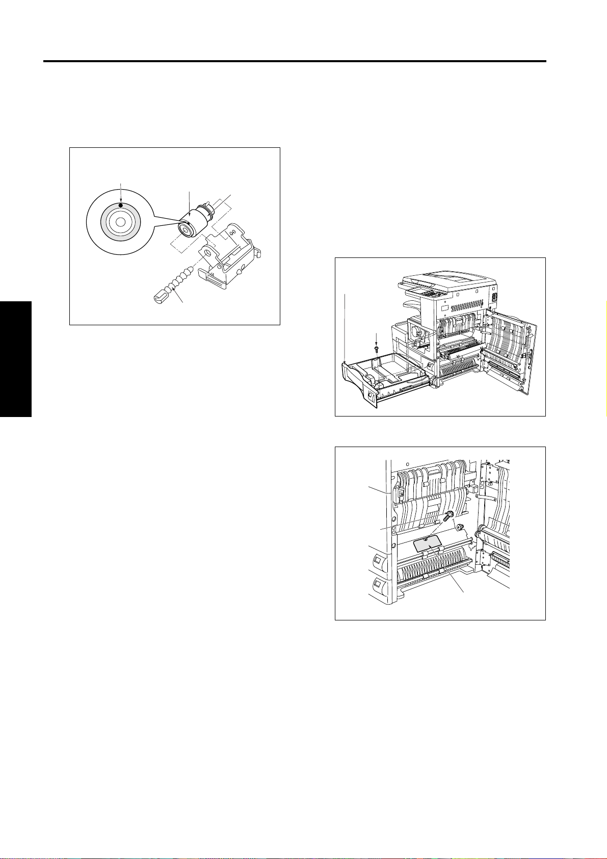
(5) Remove the 2 stopper rings, and remove the
bearings from the plate.
(6) Lift the left shaft and remove the feed roller unit.
(7) Pull out the feed shaft, and remove the double-
feed-prevention upper roller.
Feed roller
Stopper
rings
Double-feed prevention
roller (upper)
Feed roller unit
Feed shaft
Bearings
Swing shaft
(8) Remove the stopper ring, pull the guide shaft out of
the feed roller unit, and remove the feed roller.
Feed rubber Feed roller
Stopper ring
Guide shaft
Feed shaft
[4] Replacing the double feed
prevention lower rubber (upper
tray)
a. Procedure
(1) Open the ADU door, and then open the conveyance
unit.
(2) Remove the developing unit and the drum unit.
(3) Slide the upper tray out. Remove the 2 set screws
holding the tray in place, and take the tray off.
Upper tray
Set screws
(4) Remove the set screw, and remove the plate. Then
remove the set screw fastening the double feed
prevention roller unit in place.
1 OUTLINE
2 UNIT EXPLANA TION
3 DIS./ASSEMBLY
Paint mark
Double-feed prevention
roller (upper)
Stopper
ring
Double feed
prevention upper
rubber
(9) Remove the feed rubber from the feed roller.
(10) Remove the double-feed-prevention upper rubber
from the double-feed prevention roller (upper).
(11) Reinstall in the opposite sequence to removal.
Caution: Be sure to install the roller rubbers in the
correct direction.
Install so that the swing shaft goes to the
inside of the feed roller unit.
Double feed prevention unit
Set screw
Plate
Set screw
(5) From the inside of the main body, press on the two
ends of the roller unit and remove it.
3-J-3
Page 29
2
PAPER FEED UNIT
(6) While pressing on the lever on the lever click shaft,
1 OUTLINE2 UNIT EXPLANA TION3 DIS./ASSEMBL Y
pull out the shaft and then remove the double feed
prevention roller.
Double feed
Paint mark
(7) Remove the double feed prevention lower rubber
from the roller.
(8) Reinstall in the opposite sequence to removal.
Caution: Be sure to install the roller rubbers in the
correct orientation.
prevention
lower rubber
Lever click shaft
Double feed
prevention roller
[5] Replacing the feed rubber and
double feed prevention upper
rubber (lower tray)
a. Procedure
(1) Open the ADU door, and then open the conveyance
unit.
(2) Remove the developing unit and the drum unit.
(3) Slide the lower tray out. Remove the 2 set screws
holding the tray in place, and take the tray off.
Lower tray
Set screws
When installing the double-feed prevention
unit into the main body, align the unit with
the center of the marking stamped on the
main-body plate.
(4) Remove the set screw, and remove the plate.
Set screw
Plate
3-J-4
Page 30

PAPER FEED UNIT
(5) Remove the 2 stopper rings, and remove the
bearings from the plate.
(6) Lift the left shaft and remove the feed roller unit.
(7) Pull out the feed shaft and remove the double-feed
prevention roller (upper).
Feed roller unit
Bearing
Stopper
Rring
Swing
shaft
Feed
shaft
(8) Remove the 1 stopper ring, pull the guide shaft out
of the feed roller unit, and remove the feed roller.
(9) Remove the feed rubber from the feed roller.
(10) Remove the double-feed-prevention upper rubber
from the double-feed prevention roller (upper).
(11) Reinstall in the opposite sequence to removal.
Caution: Be sure to install the roller rubbers in the
correct direction.
Install so that the swing shaft goes to the
inside of the feed roller unit.
1 OUTLINE
2 UNIT EXPLANA TION
3 DIS./ASSEMBLY
Feed rubber
Guide shaft
Paint
mark
Feed roller
Stopper
ring
Double feed
prevention
roller (upper)
Feed shaft
Double feed
prevention upper
rubber
3-J-5
Page 31

PAPER FEED UNIT
1 OUTLINE2 UNIT EXPLANA TION3 DIS./ASSEMBL Y
[6]
Replacing the double feed prevention
[7] Replacing the registration rollers
2
lower rubber (lower tray)
a. Procedure
(1) Open the ADU door, and then open the conveyance
unit.
(2) Remove the developing unit and the drum unit.
(3) Slide the lower tray out. Remove the 2 set screws
holding the tray in place, and take the tray off.
(4) Open the guide plate, and remove the set screw
fastening the double feed prevention roller unit in
place.
Guide plate
Set screw
Double feed prevention
roller unit
1 and 2
a. Procedure
(1) Open the ADU door, and then open the conveyance
unit.
(2) Remove the developing unit and the drum unit.
(3) Slide the upper tray out. Remove the 2 set screws
holding the tray in place, and take the tray off.
(4) Slide the lower tray out. Remove the 2 set screws
holding the tray in place, and take the tray off.
(5) Remove the registration clutch.
(6) Remove the all external cover from the front.
Registration
roller (1)
(5) From the inside of the main body, press on the two
ends of the roller unit and remove it.
(6) While pressing on the lever on the lever click shaft,
pull out the shaft and then remove the double feed
prevention roller.
(7) Remove the double feed prevention lower rubber
from the roller.
Double feed
Paint mark
(8) Reinstall in the opposite sequence to removal.
prevention
lower rubber
Lever click shaft
Double feed
prevention roller
Registration roller (2)
(7) Stretch the 2 registration springs (front and rear)
upward and remove them from the flanges on the
registration bearings.
Registration bearings
Registration
bearings
E-rings
Registration spring
E-rings
Registration spring
3-J-6
Page 32

PAPER FEED UNIT
(8) Remove the E-ring and registration bearing at each
end of each shaft (4 E-rings and 4 bearings in
total).
Caution: Be careful to avoid dropping E-rings and
bearings into the main unit.
(9) Remove the registration rollers from the interior of
the main body.
Registration spring
Registration bearings
Registration bearings
E-rings
E-rings
Registration spring
Registration roller (1)
Registration roller (2)
(10) Reinstall in the opposite sequence to removal.
Caution: Install each registration bearing so that the
flat part is flush on the inside.
1 OUTLINE
2 UNIT EXPLANA TION
3 DIS./ASSEMBLY
Leave the registration springs hooked (do
not unhook them) when removing and
reinstalling them. Install the springs so that
the hook part is located at the top between
the two shafts.
3-J-7
Page 33

FIXING UNIT
FIXING UNIT
[1] Removing and Reinstalling the
fixing unit
Caution: Be sure that the power cord has
been unplugged from the outlet.
The fixing unit remains extremely hot
immediately after power is switched
OFF. To avoid injury from burns, do
not begin work until the fixing unit
has cooled down sufficiently.
Caution: When installing the fixing unit, be
sure to firmly tighten the unit's 2 set
screws.
a. Procedure
(1) Open the ADU door and the conveyance unit, and
loosen the 2 set screws holding the fixing unit in
place.
(2) Pull the fixing unit out toward you and remove it.
Set screws
[2] Replacing the fixing heater lamps
(main lamp and sub lamp)
Caution: Do not touch the lamp area with
bare hands.
Caution 1: When installing, be sure that manufac-
turer's mark is mounted on the front
side.
Caution 2: Do not allow the heater lamps to make
contact with the inside of the roller.
Caution 3: Install so that the main lamp is at the
top, and the sub lamp is at the bottom.
Heater cords are color-coded as
follows.
Color
Positions
Lamp
Main
Sub
Caution 4: When installing the faston terminal on
JAPAN
Front Rear Front Rear Front Rear
White
White
Black
White
the drive gear side, be sure that the installation position is correct.
U.S.A.
Red
Red
Black
Red
EUROPE
OTHERS
Blue
Blue
Black
Blue
1 OUTLINE
2 UNIT EXPLANATION
3 DIS./ASSEMBLY
conveyance
unit
(3) Reinstall in the opposite sequence to removal.
Fixing unit
a. Procedure
(1) Remove the fixing unit from the main body.
(2) Remove the set screws, and remove the two
covers (fixing front cover, and fixing rear cover).
Fixing front cover
Set screws
Fixing rear cover
3-K-1
Page 34

FIXING UNIT
(3) Detach the faston terminal at the rear of each lamp.
1 OUTLINE2 UNIT EXPLANATION3 DIS./ASSEMBLY
[3] Removing and Reinstalling the
fixing claw
2
Fasten
terminals
(4) Remove the 2 set screws, and remove the lamp
support piece (front).
(5) Detach the faston terminal at the front of each
lamp.
(6) Keeping all cord faston terminal wiring straight, pull
each fixing heater lamp toward you to remove.
Fasten terminals
Lamp support piece
(front)
Set screws
Caution 1: When installing the fixing claw, be sure
that it is oriented correctly.
Caution 2: Be sure that the claw is securely at-
tached to the claw spring.
a. Procedure
(1) Remove the fixing unit from the main body.
(2) Remove the 2 set screws, and remove the fixing
exit plate.
(3) Remove the 4 set screws, and remove the cleaner
cover.
Fixing exit plate
Set screw
(4) Unhook the spring, and remove the fixing claw.
Set screws
Cleaner cover
Set screw
Main
Fixing heater lamps
Sub
(7) Reinstall in the opposite sequence to removal.
Spring
Fixing claw
(5) Reinstall in the opposite sequence to removal.
3-K-2
Page 35

FIXING UNIT
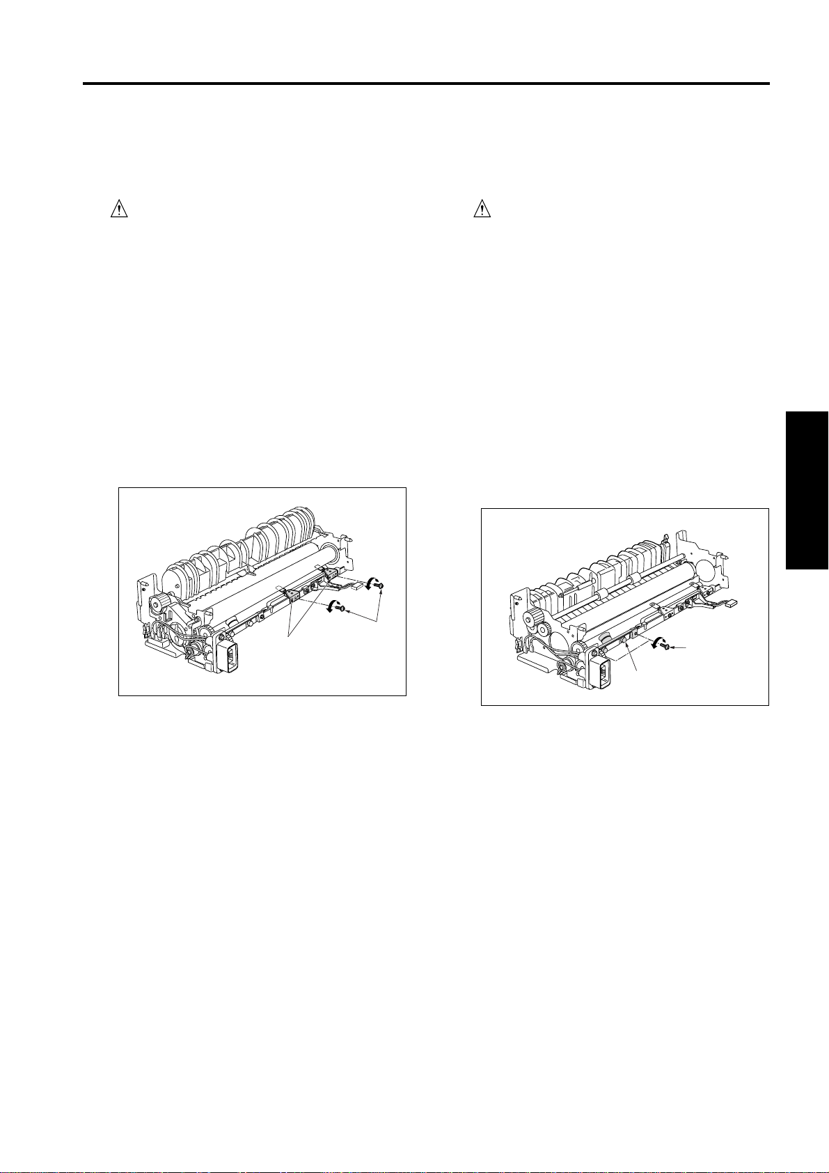
[4] Replacing the fixing web/Fixing
cleaning roller
a. Procedure
(1) Remove the fixing unit from the main body.
(2) Remove the fixing claw unit.
(3) Detach the connectors, remove the set screw at the
bottom and the 2 set screws on the cleaning unit,
and then remove the cleaning unit by pulling it out
from the fixing unit.
Connectors
Set screws
Cleaning unit
(5) Detach the springs from the bearings for the fixing
cleaning roller, and remove the E-ring from the
shaft. Move the shaft and take off the bearings.
You can then remove the fixing cleaning roller.
Fixing cleaning roller
Bearings
Springs
(6) Reinstall in the opposite sequence to removal.
1 OUTLINE
2 UNIT EXPLANATION
3 DIS./ASSEMBLY
(4) Remove the 3 set screws and remove the 3 fixing-
web bearings. Remove the web together with the
entire shaft.
Bearing
Bearing
3-K-3
Page 36

FIXING UNIT
2
1 OUTLINE2 UNIT EXPLANATION3 DIS./ASSEMBLY
[5] Removing and Reinstalling the
fixing heat roller/fixing pressure
roller
a. Procedure
(1) Remove the fixing unit from the main body.
(2) Remove the fixing claw unit.
(3) Remove the fixing cleaning unit.
(4) Remove the two fixing heater lamps
(5) Remove the 2 set screws and 2 collars for the
connector that was connected to the faston
terminal. Remove the connector.
(6) Remove the 2 set screws, and remove the lamp
support piece.
Set screws
Connectors
(10) Remove the 2 fixing bearings (one at the front, one
at the rear) from the unit.
Heat insulating
sleeve A
Fixing bearings
(11) Remove the pressure roller.
Fasten terminals
Lamp support piece
Set screws
(7) Open the fixing guide to release the pressure.
(8) Remove the ring at the rear of the heat roller, and
then remove the gear and heat insulating sleeve A,
B.
Heat insulating
sleeve A
Ring
Gear
Heat insulating
sleeve B
(rear)
Gear
Heat insulating
sleeve B
Heat roller
Heat insulating
sleeve A
Fixing pressure
roller
(12) Reinstall in the opposite sequence to removal.
Caution: Be sure that heat insulating sleeves A and
B are oriented and positioned correctly.
(9) Remove another ring, then remove the heat
insulating sleeve A (the sleeve toward the front).
Then remove the heat roller.
3-K-4
Page 37
FIXING UNIT
[6] Removing and Reinstalling the
fixing temperature sensors
Caution: After installing the fixing temperature
sensors:
Make sure that the wire bundles are
not in contact with the fixing heat
roller.
Make sure that the sensors themselves (the sensor areas) are in
contact with the fixing heat roller.
a. Procedure
(1) Remove the fixing unit from the main body.
(2) Remove the fixing claw unit.
(3) Remove the fixing cleaning unit.
(4) Remove the 2 set screws, and remove the fixing
temperature sensors.
[7] Removing and Reinstalling the
thermostat
Caution: After installing the thermostat:
Make sure that the wire bundle is
not in contact with the fixing heat
roller.
Make sure that the thermostat itself
is in contact with the fixing heat
roller.
a. Procedure
(1) Remove the fixing unit from the main body.
(2) Remove the fixing claw unit.
(3) Remove the fixing cleaning unit.
(4) Remove the heat roller.
(5) Detach the thermostat connector.
(6) Remove the 2 set screws, and remove the thermo-
stat.
1 OUTLINE
2 UNIT EXPLANATION
3 DIS./ASSEMBLY
Set screws
Fixing
temperature
sensors
(6) Reinstall in the opposite sequence to removal.
Caution: When installing the sensors, attach the
longer wire bundle to the center of the unit.
Make sure that the sensors are in contact
with the heat roller.
Set screws
Thermostat (TS)
(7) Reinstall in the opposite sequence to removal.
Caution: When installing the thermostat, install so
that the base plate fits between the unit's
sheet metal.
Make sure that the thermostat is in contact
with the heat roller.
3-K-5
Page 38

ADU/PAPER EXIT SECTION
ADU/PAPER EXIT SECTION
[1] Removing and Reinstalling the exit
sensor unit
a. Procedure
(1) Remove the read right cover.
(2) Remove the 2 set screws, and remove the right
side cover (upper).
(3) Remove the 2 set screws, and remove the cover.
Cover
(4) Remove the 2 set screws (by inserting the screw-
driver through the holes in the sheet metal). Detach
the connector at the side of the sheet metal, and
remove the exit sensor unit/1.
Set screws
(5) Remove the set screw (again, by inserting the
screwdriver through the hole), and remove the exit
limit detection actuator.
Set screw
Exit limit detection actuator
(6) Reinstall in the opposite sequence to removal.
1 OUTLINE
2 UNIT EXPLANATION
3 DIS./ASSEMBLY
Connector
Set
screws
Connector
Exit sensor unit/1
3-L-1
 Loading...