

Page 1
Chapter 2 Installation
2-1. 1312 INSTALLATION PROCEDURE ........................................... 2-1
2-1-1. Removing protective materials .............................................. 2-2
2-1-2. Preparing for the drum unit and the developing unit ........... 2-3
2-1-3. Loading the toner cartridge .................................................... 2-5
2-1-4. Installing the paper exit tray ................................................... 2-5
2-1-5. Loading copying paper ........................................................... 2-6
2-1-6. Turning on the power and initializing the developing
unit and setting the paper size ............................................... 2-7
2-2. DEVELOPING UNIT INSTALLATION PROCEDURE .................. 2-9
2-2-1. Replace the developing unit ................................................... 2-9
2-2-2. Loading the toner cartridge .................................................. 2-10
2-2-3. Initializing the developing unit ............................................. 2-10
2-3. DRUM UNIT INSTALLATION PROCEDURE ............................. 2-11
2-3-1. Replacing the drum unit........................................................ 2-11
2-3-2. Initializing the drum unit ....................................................... 2-13
2-3-3. Cleaning the pressure (rubber) roller .................................. 2-13
1
MODEL
2-4. TONER CARTRIDGE INSTALLATION PROCEDURE .............. 2-14
2-4-1. Loading the toner cartridge .................................................. 2-14
2-4-2. Replacing the cleaning pad .................................................. 2-15
2-5. CASSETTE FEEDER INSTALLATION PROCEDURE .............. 2-16
2-5-1. Installing the cassette feeder ............................................... 2-16
2-5-2. Setting the paper size............................................................ 2-17
2-6. REPLACEMENT OF THE DEVELOPER ................................... 2-18
2-6-1. Replacement of the developer.............................................. 2-18
1
2-7. PRESSURE (RUBBER) ROLLER CLEANING .......................... 2-19
1
2-7-1. Cleaning the pressure (rubber) roller (Periodic cleaning) .......... 2-19
1
2-7-2. Cleaning the pressure (rubber) roller (Additional cleaning)....... 2-21
1312
MANUAL
SERVICE HANDBOOK
REVISED EDITION
1
DATA
May.1999
PAGE
METHOD
REPLACEMENT
Page 2
2-1. 1312 INSTALLATION PROCEDURE
Powered by
Aleck Kholopov
Slash, Ltd
( 095 201 48 20
* slash@slash.ru
" http://www.slash.ru
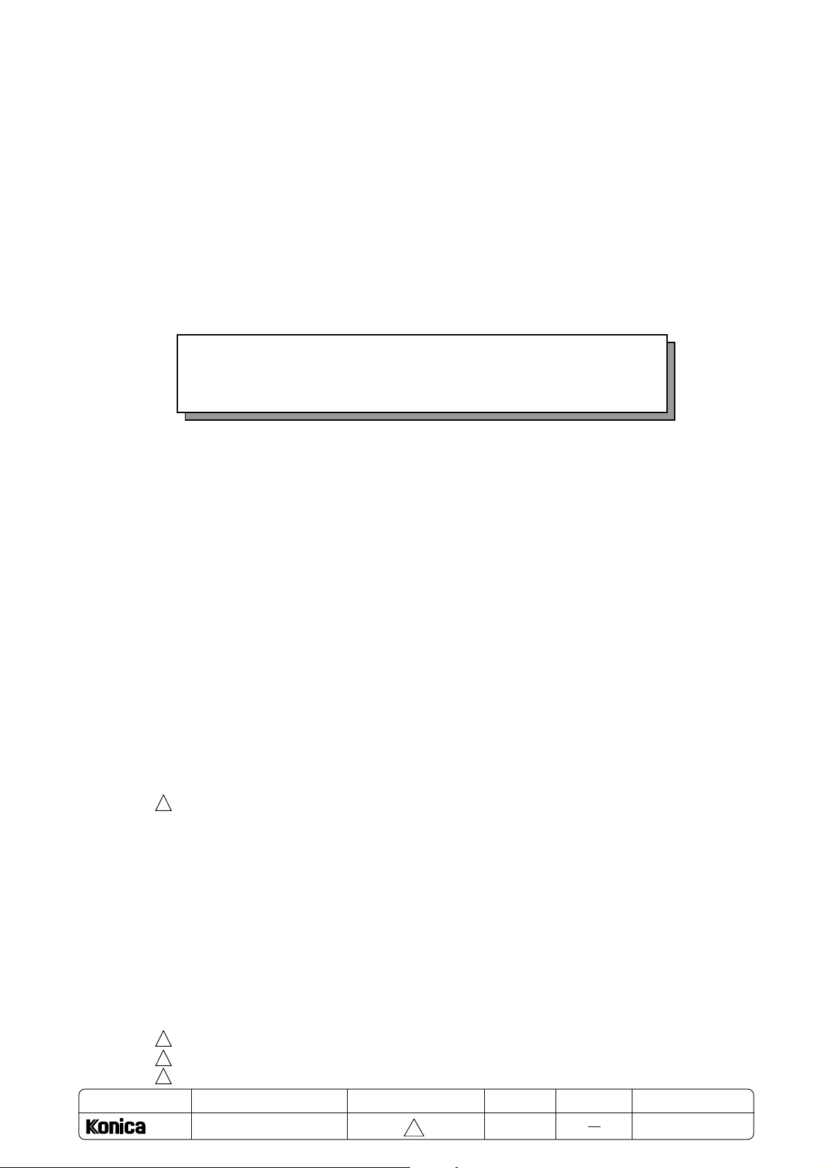
■ Package contents
Check to ensure that you have a complete set of the items shown below.
If there is a missing component. Please contact your local dealer.
Chapter 2 Installation
❏ Paper exit tray
❏ Main body
❏ Toner cartridge
❏ Developing unit
❏ Instruction manual
❏ Installation manual
❏ Power cord
❏ Drum unit
(already installed in
the main body)
❏ Cleaning pad
(already installed in
the main body)
■ Installation
Follow the procedures below to install the main body.
1. Removing protective materials
2. Preparing for the drum unit and the developing unit
3. Loading the toner cartridge
4. Installing the paper exit tray
5. Loading copy paper.
6. Turning ON the power and initializing the developing unit
and setting the paper size
2-1
Page 3
Chapter 2 Installation
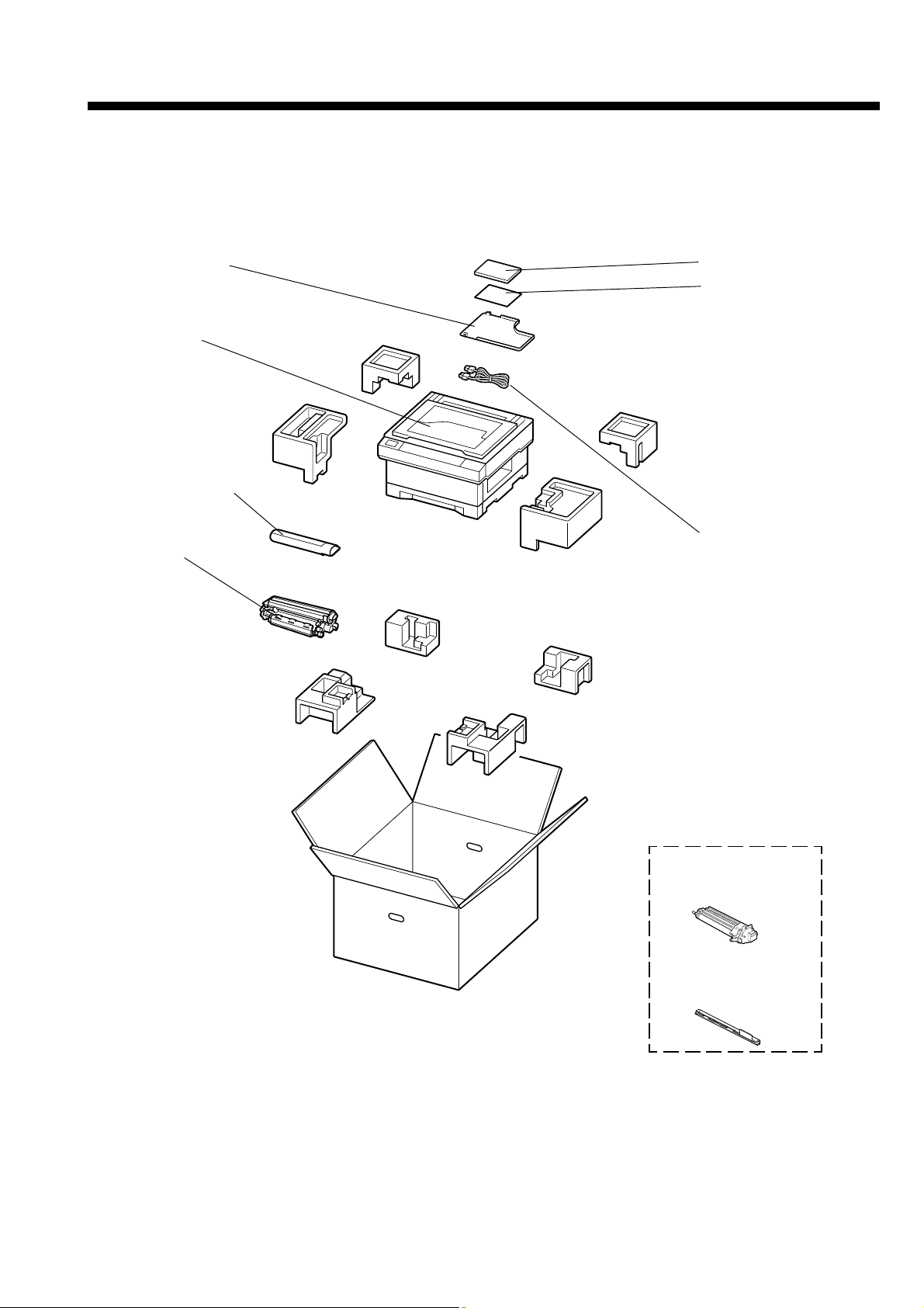
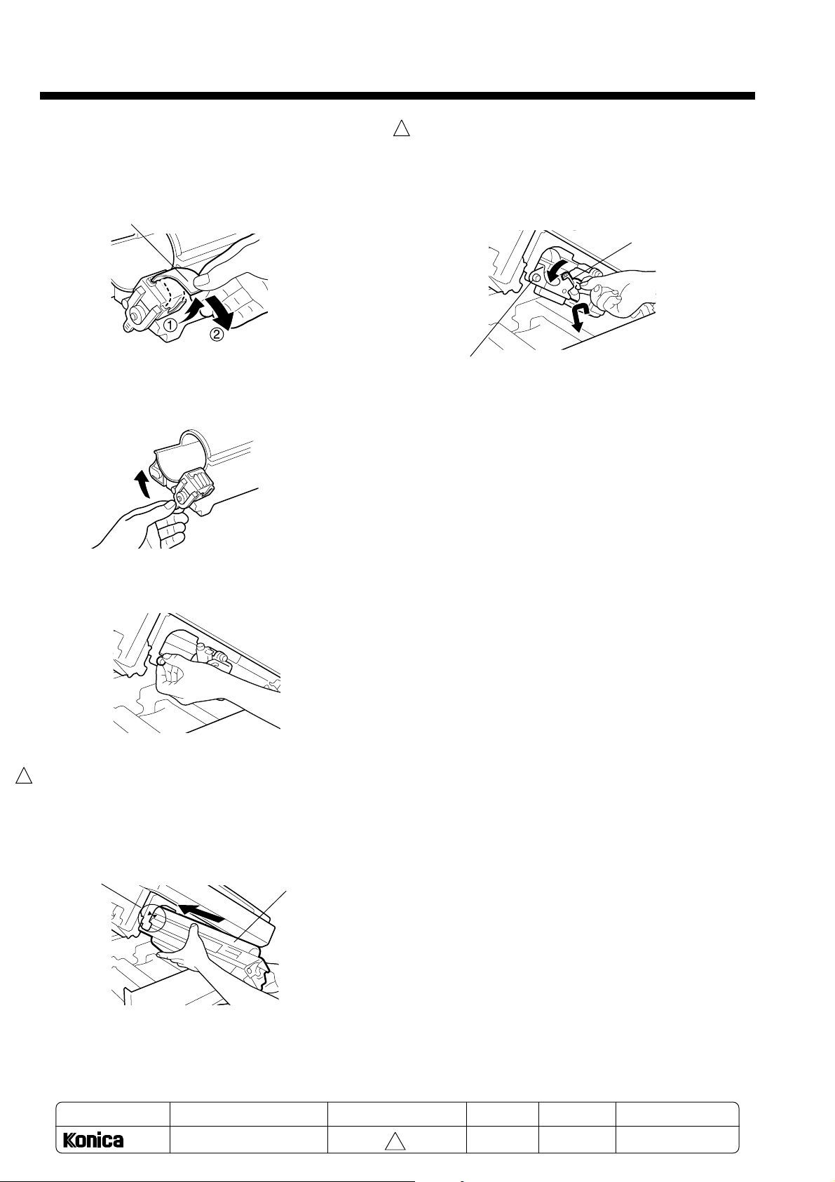
2-1-1. Removing protective materials
The copier is attached with protective materials in
order to protect it from shocks during transportation.
Be sure to remove all the protective materials when
installing the copier.
After removing the protective materials, keep them for
future transportation.
● Remove the four protective materials of the
1
platen cover.
Remove the four protective materials from the
four corners of the platen cover.
● Remove the three optical unit securing screws.
1. Remove the two screws securing the left and
right covers.
4. Pull out the drum unit.
NOTES:
• Avoid touching or scratching the drum in any
way.
• Do not expose the drum unit to light for longer
than 5 minutes. If required, cover the drum unit
with black cloth to shield it from the light.
5. Remove one screw with the red tag paper on the
bottom side of the upper unit.
Screw
2. Press the upper unit release button to open the
unit.
NOTES:
• Hold the upper unit with one hand when
pressing the upper unit release button;
otherwise the upper unit may pop up.
• Push up the upper unit until it clicks.
Upper unit
release button
3. Remove the drum unit fixing screw.
Red tag
paper
6. Reinstall the drum unit in the main body, then
1
secure it with the drum unit fixing screw.
✎When reinstalling the drum unit, align the
blue mark on the drum unit with the blue
mark on the main body.
Blue mark
Drum unit
Drum unit fixing screw
MODEL
1312
MANUAL
SERVICE HANDBOOK
REVISED EDITION
2-2
1
DATA
May.1999
PAGE
2-2
METHOD
REPLACEMENT
Page 4
Chapter 2 Installation
● Remove the protective material of the paper
tray
Withdraw the tray, and then remove the protective
material from the tray.
1. Remove the tapes and the thick paper from the
1
paper tray.
2. Lift the tray slightly and withdraw it.
3. Move the paper guide 1, then remove the
protective material.
2-1-2. Preparing for the drum unit and the developing unit
1. Remove the shield tape from the drum unit.
Shield tape
2. Move the recycle pipe to the RELEASE position.
3. Unpack the developing unit.
Tip the developing unit with the gear side
downward, and shake it up and down about four
or five times.
Then hold the developing unit in a level position,
and shake it from side to side four or five times.
Protective material
● Remove the two protective materials of the
1
transfer roller.
Remove the two protective materials from both the
ends of the transfer rollrer inside the main unit.
Transfer roller
Protective
materials
Gear
4. Remove the protective cover, then pull off the
1
protective sheet and the mat in a downward
direction.
✎It is not necessary to keep the protective
cover, protective sheet and the mat.
Mat
Protective sheet
Protective cover
MODEL
1312
MANUAL
SERVICE HANDBOOK
REVISED EDITION
2-3
1
DATA
May.1999
PAGE
2-3
METHOD
REPLACEMENT
Page 5
Chapter 2 Installation
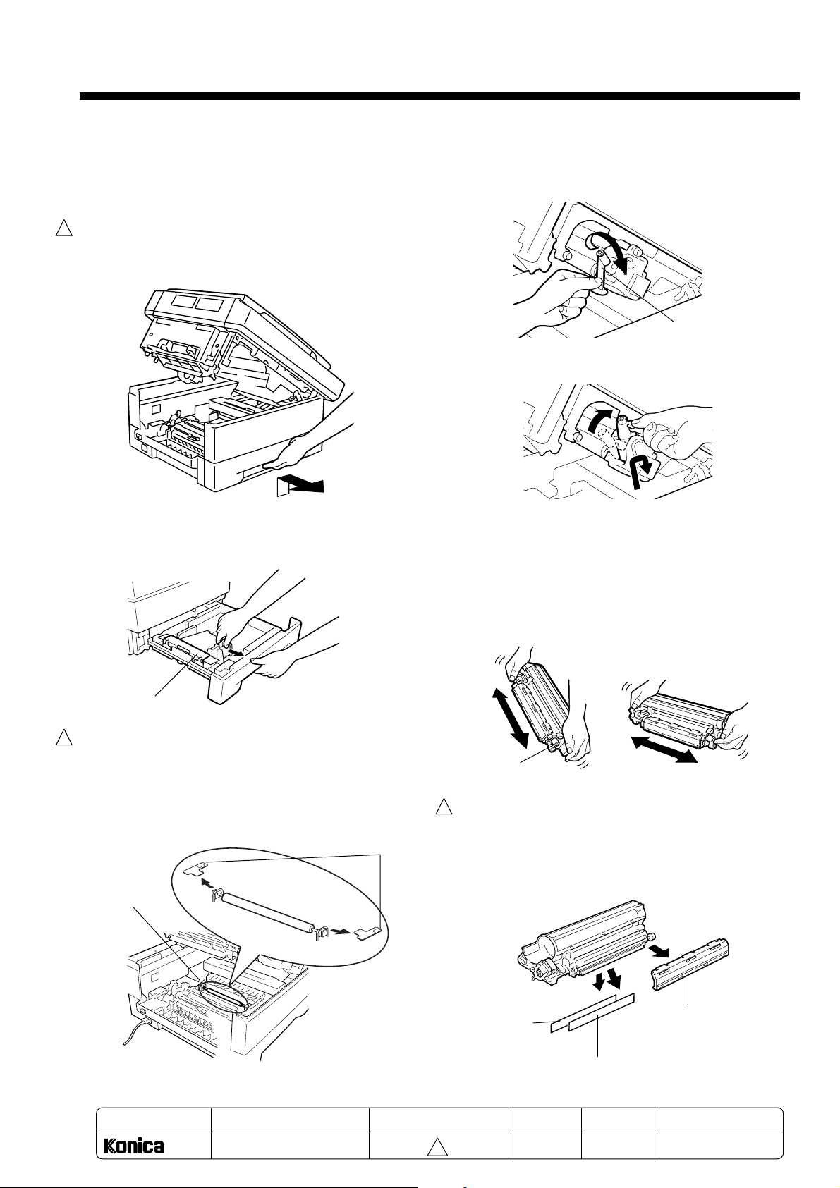
5. Peel the tape fixing the magnet tape, and then
remove the magnet tape.
✎ To prevent the developer from being
scattered, remove the magnet tape by pulling
it down slowly.
Magnet-tape
6. Remove the pipe cover.
✎ To prevent the developer from being
scattered, remove the pipe cover gently.
9. Secure the developing unit with the developing
1
unit fixing screw.
Return the recycle pipe to the SET position.
After setting the developing unit correctly, load
the toner cartridge.
Recycle
pipe
Developing unit
fixing screw
7. Remove the developing unit fixing
screw.
8. Install the developing unit in the copier main
1
body.
✎ When installing the developing unit, align the
blue mark on the developing unit with the blue
mark on the main body,
Blue mark
Developing
unit
MODEL
1312
MANUAL
SERVICE HANDBOOK
REVISED EDITION
2-4
1
DATA
May.1999
PAGE
2-4
METHOD
REPLACEMENT
Page 6
Chapter 2 Installation
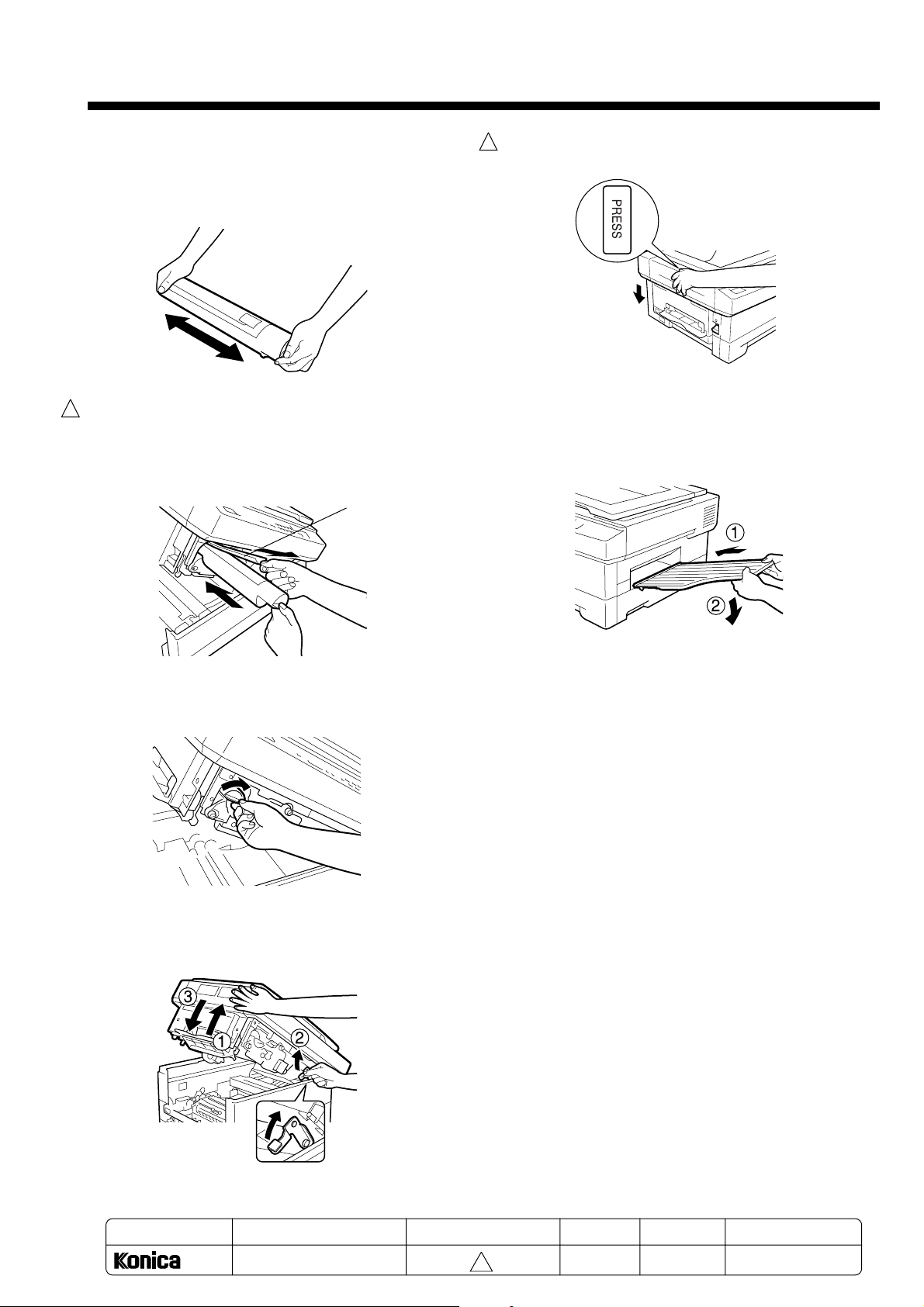
2-1-3. Loading the toner cartridge
1. Shake a new toner cartridge from side to side
four or five times.
2. While removing the shield tape gently, insert the
1
toner cartridge into the developing unit.
NOTE:
• Please insert the toner cartridge with shield
tape side up.
Shield tape
5. Close the upper unit securely, hold dawn the
1
central part of the upper unit.
2-1-4. Installing the paper exit tray
Insert the paper exit tray into the stopper of the main
body to fix it.
3. Turn the toner cartridge clockwise by 180°.
4. Lift the stopper lever while pushing up the upper
unit slightly, and then close the upper unit.
MODEL
1312
MANUAL
SERVICE HANDBOOK
REVISED EDITION
2-5
1
DATA
May.1999
PAGE
2-5
METHOD
REPLACEMENT
Page 7

Chapter 2 Installation
2-1-5. Loading the copy paper
1. Fan the copy paper enough to prevent sheets
from sticking together.
2. Lift the tray slightly and withdraw it.
3. Push down the knock-up plate.
✎Push down the knock-up plate until it is
locked securely to the bottom of the tray.
5. While pressing the guide knob, move the paper
guide 1 against the copy paper.
Paper guide 1
6. While pressing the guide knob, move the paper
guide 2 against the copy paper.
Paper guide 2
7. Remove the size label, then refold it so that it
shows the correct paper size before putting it
back into the indicator window.
Size label
4. Load copy paper in the tray.
NOTES:
• Be sure to set copy paper under the lugs.
• Load copy paper in the tray with the unwrapped
side of the package down.
• The tray is supposed to hold 250 sheets (80 g/
m2). Stack copy paper up to, but not above the
upper paper guide.
Upper paper
guide
Lugs
Indicator window
8. Push the tray gently into the copier until it clicks
into place inside the main body.
2-6
Page 8

Chapter 2 Installation
2-1-6.
Turning on the power and initialize the
developing unit and setting the paper size
● Connect the power cord
NOTE:
When turning on the power for the first time of
the use of this copier, check that three screws
fastening the optical unit during transportation
are already removed . Turning on the copier with
these screws installed may cause a machine
trouble.
1. Connect the power cord to the power supply
connector of the main body.
2. Insert the power plug into the outlet.
● Initializing the developing unit
1. Press the [SELECT PAPER] button for five
seconds.
The copier will turn to the condition for
designating initial settings.
5
0
RECALL
2. Enter the “5” , then “1” with the ten-key pad.
1 2 3 4 5
6 7 8 9 0
3. Press the [START PRINT] button.
The entered value will be established, and the
copier will start initializing the developing unit.
✎ It takes approximately 6 minutes to initialize
the developing unit.
RECALL
The power plug illustration vary with the
destination of the shipment.
3. Turn the power switch ON.
In the installation of the main body, the display
shows “P26”. Initialize the developing unit by
following the appropriate procedure.
3 4 5
8 9 0
RECALL
4. On completion of the initialization, “C- -” appears
again on the display panel.
Then, press the [STOP/CLEAR] button.
“01” will be displayed to indicate that the
machine is ready for copying.
1 2 3 4 5
6 7 8 9 0
1 2 3 4 5
6 7 8 9 0
RECALL
RECALL
2-7
Page 9

Chapter 2 Installation
● Setting the paper size
1. Press the [SELECT PAPER] button for five
seconds.
The copier will turn to the condition for
designating initial settings.
5
0
RECALL
2. Enter the code of the paper size loaded in the
tray by ten-key pad.
1 2 3 4 5
6 7 8 9 0
Paper size
L T (letter) C00
LG (legal) C01
A4 C02
B5 C03
A5 C04
F4-1:8X13" (203X30mm) C05
F4-2:8.5X13" (216X330mm) C06
F4-3:8.25X13" (210X330mm) C07
F4-4:206X337mm C08
RECALL
Code
4. Press the [STOP/CLEAR] button.
"01" will be display to indicate that the machine is
ready for copying.
Now the machine has been installed
successfully.
1 2 3 4 5
6 7 8 9 0
1 2 3 4 5
6 7 8 9 0
RECALL
RECALL
3. Press the [START PRINT] button.
The entered value is established, and “C- -” will
be displayed.
1 2 3 4 5
6 7 8 9 0
1 2 3 4 5
6 7 8 9 0
RECALL
RECALL
2-8
Page 10

2-2. DEVELOPING UNIT INSTALLATION PROCEDURE
■ Accessories ■ Installation
1. Replace the developing unit
2. Loading the toner cartridge
3. Initializing the developing unit
Developing unit...1 piece
Chapter 2 Installation
2-2-1. Replacing the developing unit
1. Press the upper unit release button to open the
unit.
NOTE:
• Hold the upper unit with a hand when pressing
the upper unit release button; otherwise the
upper unit might pop up.
• Push up the upper unit until it clicks.
• On opening the upper unit, the power supply to
the fusing unit section is turned off
automatically.
Upper unit
release button
2. Move the recycle pipe to the RELEASE position.
Recycle pipe
4. Pull out the developing unit while pushing it to
the left.
Developing
unit
5. Unpack the developing unit.
Tip the developing unit with the gear side
downward, and shake it up and sown about four
or five times.
Then hold the developing unit in a level position,
and shake it from side to side four or five times.
3. Remove the developing unit fixing screw.
Developing unit
fixing screw
MODEL
1312
SERVICE HANDBOOK
MANUAL
6. Remove the protective cover, then pull off the
1
REVISED EDITION
2-9
1
Gear
protective sheet and the mat in a downward
direction.
✎It is not necessary to keep the protective
cover, protective sheet and the mat.
Mat
Protective cover
Protective sheet
DATA
May.1999
PAGE
2-9
METHOD
REPLACEMENT
Page 11

Chapter 2 Installation
R
7. Peel the tape fixing the magnet tape, and then
remove the magnet tape.
✎To prevent the developer from being
scattered, remove the magnet tape by pulling
it down slowly.
Magnet tape
8. Remove the pipe cover.
✎To prevent the developer from being
scattered, remove the pipe cover gently.
Pipe cover
2-2-2. Loading the toner cartridge
When loading a toner cartridge, see the “TONER
CARTRIDGE INSTALLATION PROCEDURE” packed with
the toner cartridge.
2-2-3. Initializing the developing unit
1. Press the [SELECT PAPER] button for five
seconds.
The copier will turn to the condition for
designating initial settings.
2. Enter “5” , then “1” using the ten-key pad.
9. Install the new developing unit in the copier main
1
body.
✎ When installing the developing unit, align the
blue mark on the developing unit with the blue
mark on the main body.
Developing
unit
Blue
mark
10. Secure the developing unit with the developing
unit fixing screw.
11. Return the recycle pipe to the SET position.
After setting the developing unit correctly, load
the toner cartridge.
Recycle
pipe
3. Press the [START PRINT] button.
The entered value will be established, and the
copier will start initializing the developing unit.
✎It takes approximately 6 minutes to initialize
the developing unit.
4. On completion of the initialization, "C- -" appears
1
again on the display panel.
Then, press the [STOP/CLEAR] button.
"01" will be displayed to indicate that the
machine is ready for copying.
RECALL
5
0
ECALL
5
0
CAUTION
Developing unit
fixing screw
1. Do not throw the developing unit into fire
because it may violently blaze and cause burns.
2. When disposing of the developing unit please
follow the laws specific to your country and
state.
MODEL
MANUAL
REVISED EDITION
DATA
PAGE
METHOD
2-10
1312
SERVICE HANDBOOK
1
May.1999
2-10
REPLACEMENT
Page 12

2-3. DRUM UNIT INSTALLATION PROCEDURE
1
Chapter 2 Installation
■Accessories
■Installation
1. Replace the drum unit
2. Initializing the drum unit
3. Cleaning the fixing roller
Drum unit ...1 piece
Fixing roller cleaning sheet ...1 piece
1
NOTE:
• Great care should be taken when handling the drum unit not to touch the drum surface and to avoid damaging
to the drum.
• Do not expose the drum to light over 5 minutes. Exposure to light may cause abnormal printing.
If the drum unit is placed outside for a long time, take protective measures against light, for example, by
wrapping the drum with a black cloth.
2-3-1. Replace the drum unit
3. Remove the developing unit fixing screw.
1. Press the upper unit release button to open the
unit.
NOTE:
• Hold the upper unit with one hand when
pressing the upper unit release button;
otherwise the upper unit might pop up.
Developing unit
fixing screw
• Push up the upper unit it clicks.
• On opening the upper unit, the power supply to
the fusing unit section is turned off
automatically.
4. Pull out the developing unit while pushing it to
the left.
Upper unit
release button
Developing unit
2. Move the recycle pipe to the RELEASE position.
Recycle pipe
MODEL
MANUAL
REVISED EDITION
5. Remove the drum unit fixing screw.
Drum unit
fixing screw
DATA
PAGE
METHOD
2-11
1312
SERVICE HANDBOOK
1
May.1999
2-11
REPLACEMENT
Page 13

Chapter 2 Installation
Powered by
Aleck Kholopov
Slash, Ltd
( 095 201 48 20
* slash@slash.ru
" http://www.slash.ru
6. Pull out the drum unit.
Drum unit
7. Install a new drum unit in the main body.
1
✎When installing the drum unit, align the blue
mark on the drum unit with the blue mark on
the main body.
Blue mark
Drum unit
1
11. Reinstall the developing unit in the main body.
✎When reinstalling the developing unit, align
the blue mark on the developing unit with the
blue mark on the main body.
Developing
unit
Blue
mark
12. Secure the developing unit with the developing
unit fixing screw.
13. Return the recycle pipe to the SET position.
Recycle
pipe
Developing unit
fixing screw
8. Secure the drum unit with the drum unit fixing
screw.
9. Remove the shield tape from the drum unit.
Drum unit
fixing screw
Shield tape
10. Move the recycle pipe to the RELEASE position.
Recycle pipe
14. Lift the stopper lever while pushing up the upper
unit slightly, and then close the upper unit.
Stopper
lever
15. Close the upper unit securely, hold down the
central part of the upper unit.
MODEL
1312
MANUAL
SERVICE HANDBOOK
REVISED EDITION
2-12
1
DATA
May.1999
PAGE
2-12
METHOD
REPLACEMENT
Page 14

Chapter 2 Installation
2-3-2. Initializing the drum unit
1. Press the [SELECT PAPER] button for five
seconds.
The copier will turn to the condition for
designating initial settings.
4 5
9 0
RECALL
2. Enter the “5” , then “0” with the ten-key pad.
3. Press the [START PRINT] button.
The entered value will be established, and the
copier will start initializing the drum unit.
✎It takes approximately 1 minutes to initialize
the drum unit.
1
2-3-3. Cleaning the pressure (rubber) roller
1. Clean the pressure (rubber) roller according to
the instruction of the supplied fixing roller
cleaning sheet.
CAUTION
1. Do not throw the drum unit into fire because it
may violently blaze and cause burns.
2. When disposing of the drum unit please follow
the laws specific to your country and state.
1 2 3 4 5
6 7 8 9 0
RECALL
4. On completion of the initialization, "C- -" appears
again on the display panel.
Then, press the [STOP/CLEAR] button.
"01" will be displayed to indicate that the
machine is ready for copying.
3 4 5
8 9 0
RECALL
3 4 5
8 9 0
RECALL
MODEL
1312
MANUAL
SERVICE HANDBOOK
REVISED EDITION
2-13
1
DATA
May.1999
PAGE
2-13
METHOD
REPLACEMENT
Page 15

Chapter 2 Installation
Powered by
Aleck Kholopov
Slash, Ltd
( 095 201 48 20
* slash@slash.ru
" http://www.slash.ru
2-4. TONER CARTRIDGE INSTALLATION PROCEDURE
■ Accessories
Toner cartridge...1 piece
Cleaning pad...1 piece
2-4-1. Loading the toner cartridge
1. Press the upper unit release button to open the
unit.
NOTE:
• Hold the upper unit with one hand when
pressing the upper unit release button;
otherwise the upper unit might pop up.
• Push up the upper unit until it clicks.
• On opening the upper unit, the power supply to
the fixing unit section is turned off
automatically.
■ Installation
1. Loading the toner cartridge
2. Replacing the cleaning pad
4. Shake a new toner cartridge from side to side
four or five times.
5. While removing the shield tape gently, insert the
1
toner cartridge into the developing unit.
NOTE:
Please insert the toner cartridge with shield
tape side up.
Upper unit
release button
2. Turn the toner cartridge a little to both sides two
or three times to empty any remaining toner into
the developing unit.
3. Turn the toner cartridge counterclockwise by
180°
, then pull out it.
Shield tape
6. Turn the toner cartridge clockwise by 180°.
MODEL
1312
MANUAL
SERVICE HANDBOOK
REVISED EDITION
2-14
1
DATA
May.1999
PAGE
2-14
METHOD
REPLACEMENT
Page 16

Chapter 2 Installation
Powered by
Aleck Kholopov
Slash, Ltd
( 095 201 48 20
* slash@slash.ru
" http://www.slash.ru
2-4-2. Replace the cleaning pad
1. Slide the cleaning pad to the rear, then remove it
while pulling up on the front side.
Cleaning pad
2. Install a new cleaning pad to rear, then slide it to
the front to install firmly.
NOTE:
After installing a new cleaning pad, pull it upward
to check that it is firmly installed. If not firmly
installed, soiling of copy images and mishandled
paper may occur.
1
CAUTION
1. Do not throw the toner cartridge and the
cleaning pad into fire because it may violently
blaze and cause burns.
2. When disposing of the toner cartridge and the
cleaning pad please follow the laws specific to
your country and state.
3. Lift the stopper lever while pushing up the upper
unit slightly, and then close the upper unit.
Stopper
lever
4. Close the upper unit securely, hold down the
1
central part of the upper unit.
MODEL
1312
MANUAL
SERVICE HANDBOOK
REVISED EDITION
2-15
1
DATA
May.1999
PAGE
2-15
METHOD
REPLACEMENT
Page 17

Chapter 2 Installation
2-5. CASSETTE FEEDER INSTALLATION PROCEDURE
■ Accessories
Cassette feeder
...1 piece
Screw M4x10
...3 pieces
Washer screws
M4x8...1 piece
2-5-1. Installing the cassette feeder
1. Turn the power switch OFF and unplug the
power cord from the outlet.
2. Remove the rear cover fixing screw, then cut the
port cover.
Rear cover
fixing screw
Port cover
■Items of installation
1. Installing the cassette feeder
2. Setting the paper size
5. Pull out the main body tray.
6. Secure the main body to the cassette feeder with
three screws (M4x10).
3. Remove the protective material.
Protective
material
4. Place the main body on the cassette feeder, so
that the guide pins are aligned with the alignment
holes.
✎Be careful not to catch the connective cord
and the earth wire between the main body
and the cassette feeder.
Earth wire Connective cord
Guide pins
Screws M4x10
7. Connect the connective cord to the CN171 and
fix the earth cord with a washer screw (M4x8).
✎Be careful to fix the earth cord in a downward
direction as illustrated below.
CN171
Washer screw M4x8
Earth cord
2-16
Page 18

Chapter 2 Installation
Powered by
Aleck Kholopov
Slash, Ltd
( 095 201 48 20
* slash@slash.ru
" http://www.slash.ru
●If the cassette feeder is equipped with a heater,
follows the steps (1) and (2) below to connect the
connectors.
(1) Remove the connective cover.
(One screw)
Connective cover
(2) Pull the two-pin connector out of the main body
and connect it to the two-pin connector of the
cassette feeder.
8. Attach the port cover (or the connective cover in
the case of the cassette feeder with a heater)
with a screw.
2-5-2. Setting the paper size
1. Press the [SELECT PAPER] button for five
seconds.
The copier will turn to the conditon for
designating initial settings.
4 5
9 0
RECALL
2. Enter the paper size code by ten-key pad.
1 2 3 4 5
6 7 8 9 0
Paper size
L T (letter) C10
LG (legal) C11
A4 C12
B5 C13
A5 C14
F4-1: 8”x13”(203x30mm) C15
F4-2: 8.5”x13”(216x330mm) C16
F4-3: 8.25”x13”(210x330mm) C17
F4-4: 206x337mm C18
3. Press the [START PRINT] button.
The entered value will be established.
RECALL
Code
Port cover
Connective cover
9. Pull out the cassette feeder paper tray then
remove the protective material.
10. Set copy paper in the tray.
11. Insert the power cord plug into the outlet, then
turn the power switch ON.
After turning on the machine, Set the paper size.
1 2 3 4 5
6 7 8 9 0
RECALL
4. “C - -”appears again on the display panel, then
press the [STOP/CLEAR] button.
“01” will be display to indicate that the machine is
ready for copying.
3 4 5
8 9 0
RECALL
3 4 5
8 9 0
RECALL
2-17
Page 19

Chapter 2 Installation
2-6. REPLACEMENT OF THE DEVELOPER
2-6-1. Replacement of the developer
1. Remove three screws and the Cover(DE) of
the developing unit.
2. Turn the developing unit upside down and
dump the developer out of the unit.
✎Shake the developing unit right and left at
some times and turn the Magnet Roller in the
upper direction to dump the developer.
1
4. After shaking the bottle to mix the developer,
put the developer over the developing unit.
NOTE:
Make sure that no developer remains on the
Doctor Blade, the top of the Box(DE) and the
surface of the Magnetic Roller outside of the
Doctor Blade.
5. Reinstall the Cover(DE) and set the
developing unit in the copier.
6. Initialize the developing unit according to the
appropriate procedure.
☞ 2-10
3. Using a brush or a vacuum cleaner, clean the
Doctor Blade and the surface of the Magnet
Roller as shown in the area of oblique lines.
MODEL
1312
SERVICE HANDBOOK
MANUAL
REVISED EDITION
2-18
1
DATA
May.1999
PAGE
2-18
METHOD
REPLACEMENT
Page 20

2-7. PRESSURE (RUBBER) ROLLER CLEANING
2-7-1. Cleaning the pressure (rubber) roller (Periodic cleaning)
Perform the following procedure after replacing a drum unit.
Procéder comme suit après le remplacement de l’unité tambour.
Befolgen Sie nach dem Austausch der Trommeleinheit die folgenden Prozeduren.
Eseguire le procedure che seguono dopo aver sostituito l’unità a tamburo.
Realice el siguiente procedimiento cada vez que se cambie una unidad de tambor.
1. After replacing a drum unit, make10 copies
of the “Black line pattern” on the back of this
page.
1. Après le remplacement de l’unité tambour,
prendre 10 copies du “Black line pattern” au dos
de cette page.
1. Erstellen Sie zehn Kopien des “Linienmusters” auf
der Rückseite dieses Blatts.
1. Dopo aver sostituito l’unità a tamburo fare 10
copie del “Diagramma linee nere” che si trova sul
retro di questa pagina.
1. Después de cambiar una unidad de tambor, haga
10 copias del “Patrón de lÌnea negra” atrás de esta
página.
Chapter 2 Installation
2. Set one copy of the “Black line pattern” onto the
sheet bypass tray with its face down and the arrow
indication facing the manual feed inlet.
2. Placer une copie de “Black line pattern” sur le
plateau auxiliaire, face vers le bas, et la flèche
dirigée vers l’entrée d’alimentation manuelle.
2. Legen Sie eine Kopie des “Linienmusters” in den
Stapeleinzug mit der bedruckten Seite nach unten
und dem Pfeil zum Kopierer gerichtet.
2. Impostare una copia del “Diagramma linee nere”
sul vassoio di inserzione fogli manuale, con la
faccia rivolta verso il basso e la freccia rivolta verso
l’entrata di inserzione fogli manuale.
2. Coloque una copia del “Patrón de línea negra” en
la bandeja de alimentación directa cara abajo y con
la indicación de flecha apuntando hacia la entrada
de la alimentación manual.
3. Press [START PRINT] button.
4. Repeat steps 2 and 3 for the rest of the 10 copies
made in step 1.
3. Appuyer sur la touche [START PRINT].
4. Répéter les étapes 2 et 3 pour le reste des 10
copies prises à l’étape 1.
3. Drücken Sie die [START PRINT]-Taste.
4. Wiederholen Sie die Schritte 2 und 3 für den Rest
der in Schritt 1 erstellten 10 Kopien.
3. Pemere il tasto [START PRINT].
4. Ripetere i passi 2 e 3 per il resto delle dieci copie
fatte nel passo 1.
3. Oprima el botón [START PRINT].
4. Repita los pasos 2 y 3 para el resto de las 10
copias hechas en el paso 1.
MODEL
1312
MANUAL
SERVICE HANDBOOK
REVISED EDITION
2-19
1
DATA
May.1999
PAGE
2-19
METHOD
ADDITION
Page 21

Chapter 2 Installation
2-20
Page 22

2-7-2. Cleaning the pressure (rubber) roller (Additional cleaning)
When the “cleaning the pressure (rubber) roller
(periodic cleaning, refer to 2-7-1)” doesn’t work so
good, do the following operations.
1. Make one copy of the “Solid black pattern”
on the back of this page.
Solid black partern
Chapter 2 Installation
3.Press “START PRINT” button.
4.Repeat steps 1 to 3 until the pressure
(rubber) roller is cleaned.
2.Set one copy of the “Solid black partern” onto
the sheet bypass tray with it facedown.
MODEL
1312
MANUAL
SERVICE HANDBOOK
REVISED EDITION
2-21
1
DATA
May.1999
PAGE
2-21
METHOD
Addition
Page 23

Chapter 2 Installation
2-22
 Loading...