

Page 1

Chapter 6 Mechanism
6-1. Copy process ....................................................... 6-1
6-2. Front cross-section (Main mechanism
parts layout drawing) .......................................... 6-3
6-3. Drive conveyance system diagram .................... 6-4
Page 2
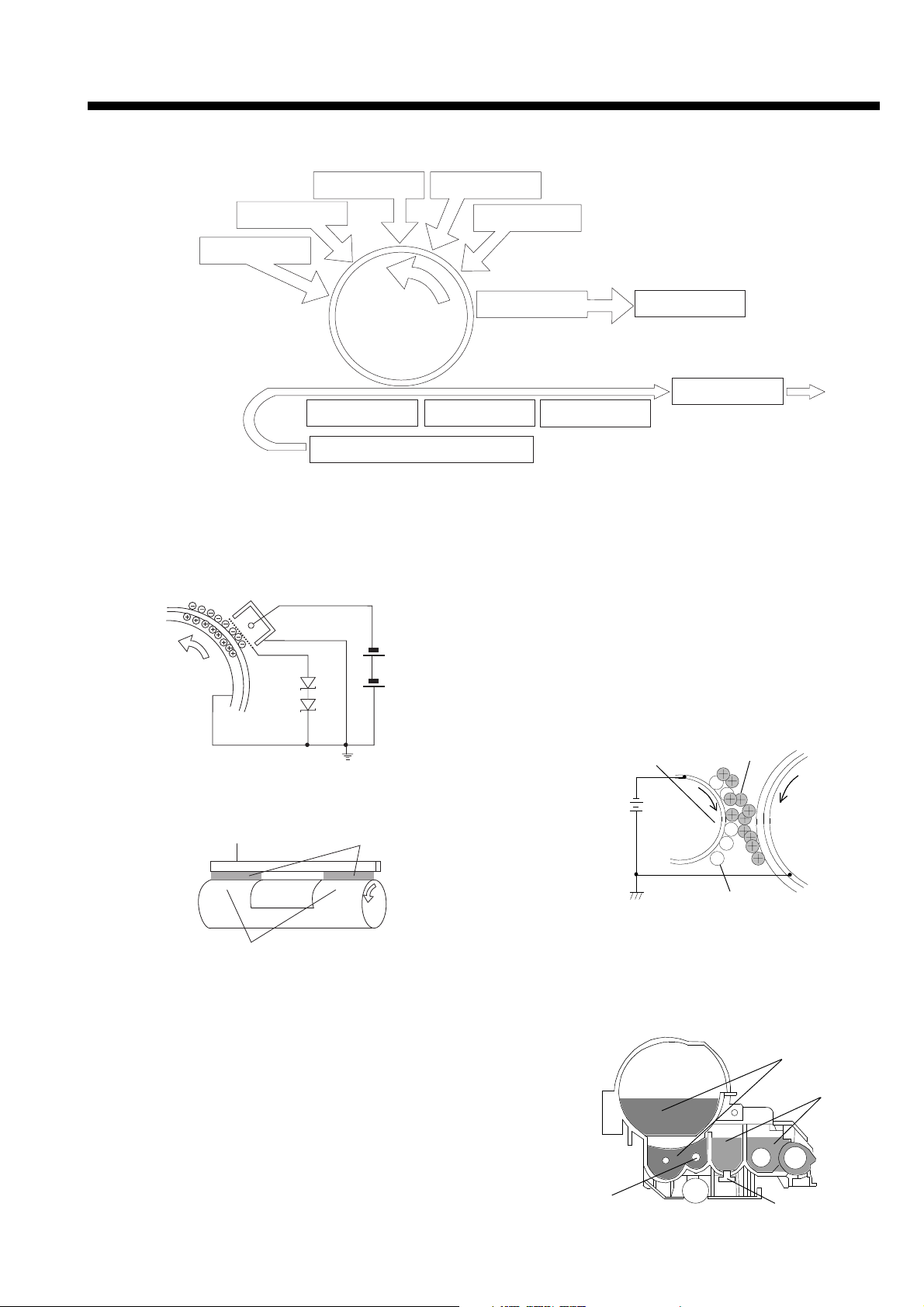
6-1. Copy process
Chapter 6 Mechanism
2. Side erase
1. Charging
3. Exposure
4. Development
Photosensitive
OPC drum
5.Transfer
5.Separation 5.Conveyance
8.Paper feed cassette
1. Charging
A high voltage of -4 to -5.5KV, output from the high
voltage PCB (UNITHV), is applied on the charge
corona unit. The grid mesh between the
photosensitive OPC drum and charger is grounded via
a 780V Zenner diode, keeping the surface of the
photosensitive drum constant at -720V.
7.Main erase
7.Cleaning
7.Toner collection
6.Fixing
4. Development
1) The toner contained in the developer is positively
charged when agitated. The charged toner is
developed (magnetic brush method) when contacted against the OPC drum by the carrier (ferrite)
and magnet roller. The toner adheres only at the
sections of the OPC drum where there is an image,
and creates a visible image. There is a slight
negative charge even at the sections with no image
(white sections), and some toner will adhere. The
bias voltage -170V, output from the high voltage
PCB (UNITHV) is applied on the magnet roller to
prevent this adhesion.
2. Side erase
The non-image area such as the edges during reduction copy, of the OPC drum surface after charging is
discharged with the side erase lamp.
Side erase lamp
Reduction
image area
Non-image area
3. Exposure
The light irradiated from the exposure lamp exposes the
photosensitive surface via the six mirrors and lens.
Document table glass
No. 4 mirror
No. 5 mirror
No. 6 mirror
Slit
OPC drum
Erase light
OPC drum
Document (back side is image)
Exposure
No. 1 mirror
lamp
No. 1 scanner
No. 2 scanner
No. 2 mirror
No. 3 mirror
Magnet roller
Toner
OPC drum
Carrier
2) The density of the toner contained in the developer
is kept constant by the toner sensor (magnetic
sensor). When the toner sensor detects a low
density, the supply screw provided at the bottom of
the toner box rotates, and the toner is supplied into
the developer.
Toner
Developer
Supply screw
Toner sensor
6-1
Page 3

Chapter 6 Mechanism
5. Transfer, separation and conveyance
1) Transfer
The paper fed from the paper cassette is conveyed
between the OPC drum and TC roller. A transfer
voltage of -1 to -2KV, output from the high voltage
PCB (UNIT HV) is applied on the TC roller, and the
paper is negatively charge. As the toner on the
OPC drum is positively charged, the toner image is
transferred onto the paper. At areas other than the
transfer area, the transfer voltage is changed to a
positive voltage (600V), so the toner adhered on
the transfer roller surface is returned to the OPC
drum.
OPC drum
Toner image
Transfer roller
2) Separation
As the diameter of the OPC is small at 30mm, the
paper after transfer is naturally separated (curvature separation) by the firmness of the paper.
Copy paper
1
7. Cleaning
1) Blade cleaning, toner recycle
The toner left on the OPC drum after the transfer
process is scraped off by the cleaning blade
(urethane rubber).
The toner scraped off is returned to the developing
unit by the screw conveyor, and is reused.
Cleaning blade
OPC drum
Screw conveyor
2) Main erase lamp
A slight residual potential is left on the OPC drum
surface after the toner is scraped off. As the OPC
drum is repeatedly used, the residual potential is
completed erased by the main erase lamp.
Main erase lamp
Drum diameter
large
Copy paper
Winds up
Drum diameter small
Curvature separation
3) Conveyance
As the distance between the transfer process and
fusing process in this machine is short, the paper is
conveyed to the fusing process by the regist roller
and transfer roller.
Regist roller
Transfer roller
6. Fixing
The toner image transferred onto the paper is fixed by
the heat roller’s heat and pressure roller’s pressure.
The fixed paper is peeled off by the separation claws,
and is exited.
Heat roller
Separation claw
Copy paper
8. Paper feed
The paper in the paper feed cassette is separated by
the claws on both edges, and only one sheet is
conveyed into the unit by the paper feed roller (segment roller). When the paper feed is completed, the
segment roller stops at a position where it does not
contact the paper, so the paper pressing load is
reduced.
Segment roller during paper feed
Pressue roller
MODEL
1312
Exit tray
Pressue spring
MANUAL
SERVICE HANDBOOK
REVISED EDITION
6-2
1
DATA
May.1999
Segment roller stop position after paper feed
PAGE
6-2
METHOD
REPLACEMENT
Page 4
1
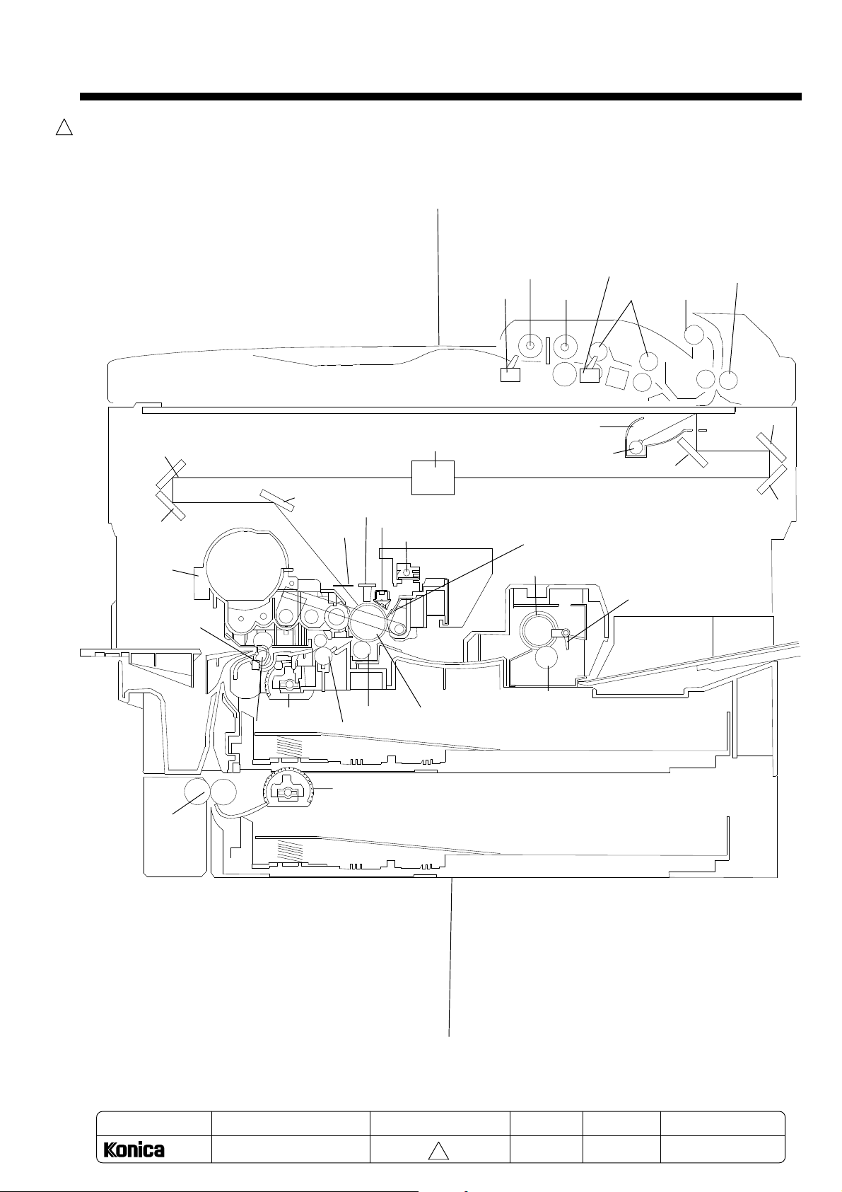
6-2. Front cross-section (Main mechanism parts layout drawing)
SDH
Chapter 6 Mechanism
No. 4 mirror
No. 5 mirror
Developer unit
JAM1 sensor
No.6 mirror
Side erase lamp
Shield glass
Lens
Charge corona unit
Main erase (cleaning) lamp
Paper feed roller
S1 sensor
Separation roller
Reflector (reflection mirror)
Exposure lamp
Cleaning blade
Heat roller
S2 sensor
Conveyance
roller
No. 1 mirror
JAM2 sensor
Turn roller
Paper exit roller
No. 2 mirror
No. 3 mirror
Relay roller
Paper feed roller
Slip roller
Transfer roller
Regist roller
Paper feed roller
OPC drum
Pressure (rubber) roller
Cassette feeder (option)
MODEL
1312
MANUAL
SERVICE HANDBOOK
REVISED EDITION
6-3
1
DATA
May.1999
PAGE
6-3
METHOD
REPLACEMENT
Page 5
Chapter 6 Mechanism
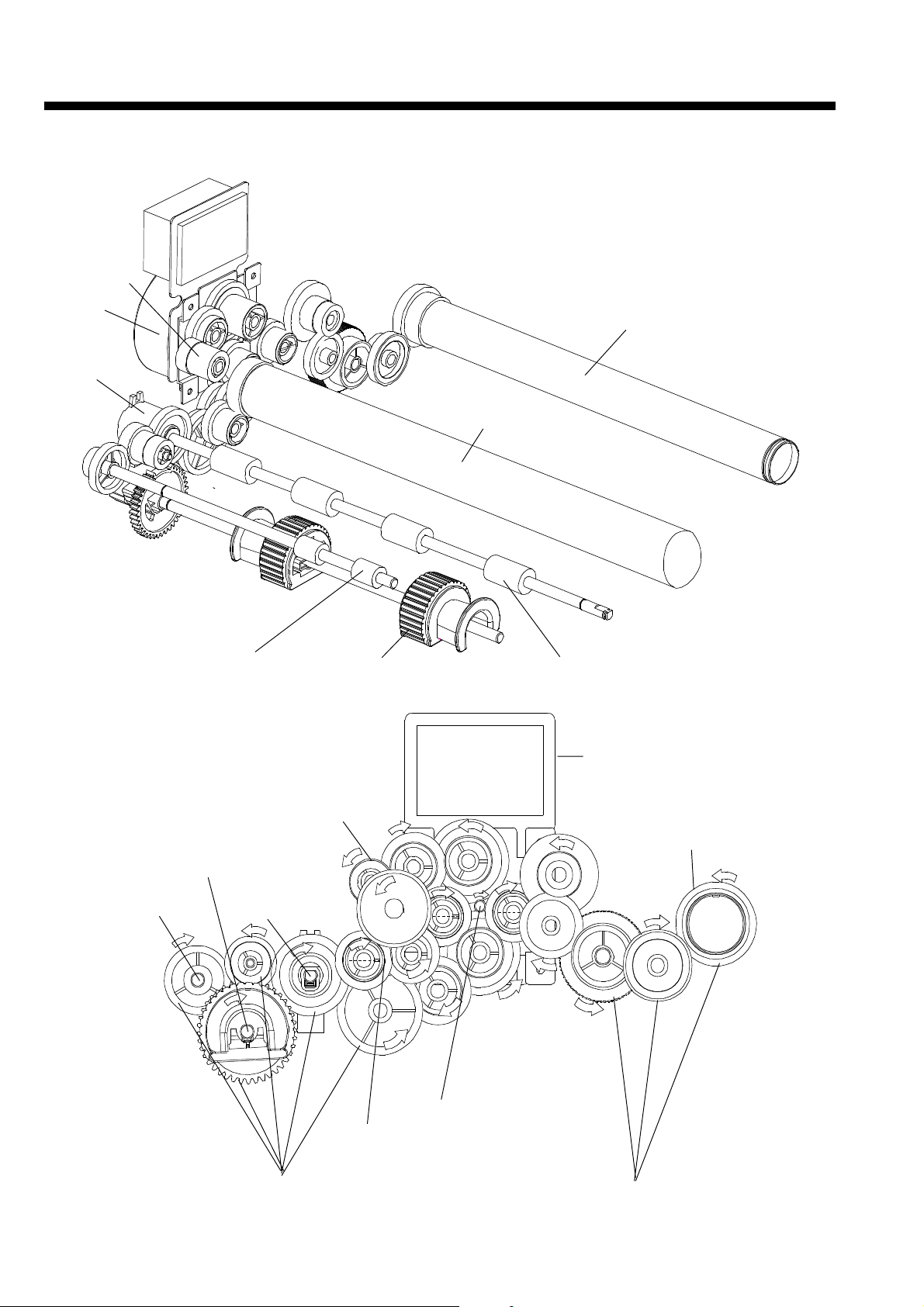
6-3. Drive conveyance system diagram
Developing unit drive gear
Main motor
Regist clutch
Slip roller Paper feed (segment) roller
Heat roller
OPC drum
Regist roller
Main motor
Paper feed (segment) roller
Slip roller
Paper feed unit gear
Developing unit drive gear
Heat roller
Resist roller
Main motor shaft (gear)
OPC drum
Fixing unit gear
6-4
 Loading...