

Page 1

Chapter 4 Adjustment
4-1. Toner density.........................................................4-1
4-2. Fusing temperature .............................................. 4-1
4-3. Exposure voltage ..................................................4-2
4-4. Image position.......................................................4-2
4-4-1. Center position ..................................................4-2
4-4-2. Leading edge position.......................................4-3
4-4-3. Image skew.........................................................4-3
4-5. Magnification adjustment.....................................4-3
4-5-1. Feeding direction (Vertical magnification) ......4-3
4-5-2. Crosswise direction
(Horizontal magnification) ................................. 4-4
4-6. Optical section adjustment ..................................4-4
4-6-1. Light distribution ...............................................4-4
4-6-2. Scanner reference position .............................. 4-5
4-6-3. Lens reference position ....................................4-5
4-6-4. Diagonal distortion ............................................4-5
4-6-5. Image distortion ................................................. 4-5
4-6-6. Focus ..................................................................4-5
4-6-7. Image center position........................................4-6
4-6-8. Focus (Horizontal blurring)...............................4-6
4-6-9. Horizontal magnification ................................... 4-6
4-7. Leading and trailing edges erase width..............4-6
Page 2
Chapter 4 Adjustment
4-1. Toner density
The toner density adjustment procedure is used to
adjust the black matte section density or the toner
consumption amount, etc.
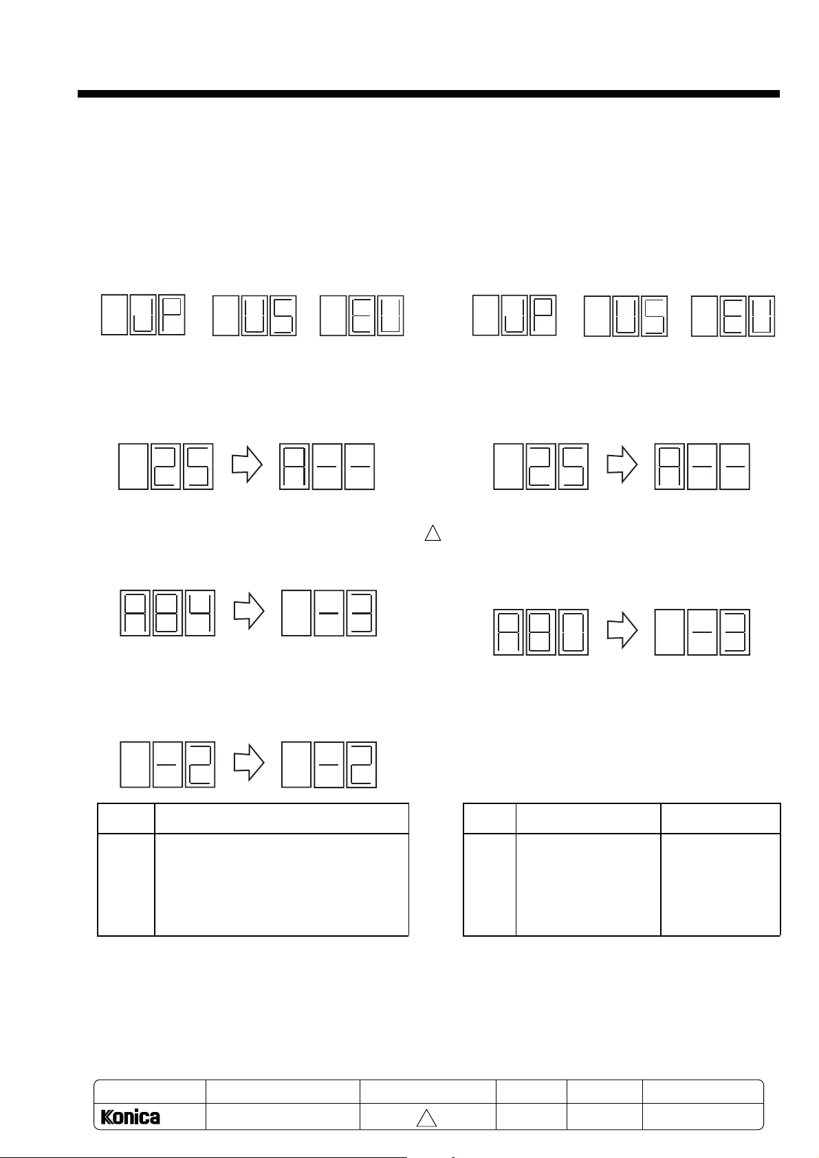
1) Procedure
1. Call out the service mode.
(Press the Enlarge key and Reduce key for 5 sec.
in the Scale 1: 1 mode, and press the 0 key within
2 sec. after the local destination displayed)
Japan
US
2. Select 25 mode.
(Input 25 with the numeric keypad, and then press
the Start Print key.)
Europe
4-2. Fusing temperature
The fusing temperature adjustment is carried out to
improve the fusing performance when copying onto
thick paper, and to uncurl thin paper, etc.
1) Procedure
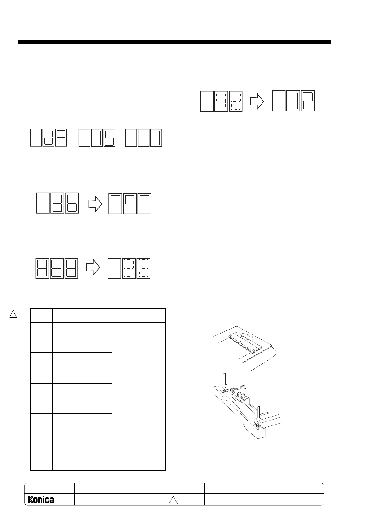
1. Call out the service mode.
(Press the Enlarge key and Reduce key for 5 sec.
in the Scale 1: 1 mode, and press the 0 key within
2 sec. after the local destination displayed)
Japan
US
2. Select 25 mode.
(Input 25 with the numeric keypad, and then press
the Start Print key.)
Europe
3. Select address 84 (toner density control setting).
(Input 84 with the numeric keypad, and then press
the Start Print key.)
4. Change the setting data to the required data (1 to 5).
(Input the data with the numeric keypad, and then
press the Start Print key.)
Data Toner density
1 Lighter
2
↑
3 Default value
4
↓
5 Darker
3. Select address 80 (Fusing temperature control
1
setting).
(Input 80 with the numeric keypad, and then press
the Start Print key.)
4.
Change the setting data to the required data (1 to 5)
(Input the data with the numeric keypad, and then
Data Fusing temperature Remarks
1 182ºC Lower
2 185ºC
3 188ºC Default value
4 190ºC
5 193ºC Higher
.
↑
↓
5. Press the Clear/Stop key until the normal mode
appears (3 presses).
(When the Clear key is pressed once, the state
will return to the previous state.)
Note: After changing this setting, the changed
toner density will not be achieved immediately.
MODEL
1312
SERVICE HANDBOOK
MANUAL
REVISED EDITION
press the Start Print key.)
5. Press the Clear/Stop key until the normal mode
appears (3 presses).
(When the Clear key is pressed once, the state will
return to the previous state.)
DATA
PAGE
4-1
1
May.1999
4-1
REPLACEMENT
METHOD
Page 3
Chapter 4 Adjustment
4-3. Exposure voltage
The exposure lamp voltage adjustment is carried out
to change the adjustment width of the density control
knob on the operation panel.
1) Procedure
1. Call out the service mode.
(Press the Enlarge key and Reduce key for 5
sec. in the Scale 1: 1 mode, and press the 0 key
within 2 sec. after the local destination displayed)
Japan
US
2. Select 36 mode.
(Input 36 with the numeric keypad, and then
press the Start Print key.)
3. Select the code to be changed (86 to 90: AVR
adjustment 1 to 5).
(Example: Input 88 with the numeric keypad, and
then press the Start Print key.)
Europe
4. Change the setting data to the required data (01 to
64).
(Input the data with the numeric keypad, and then
press the Start Print key.)
Changed data
(example: 42) blinks
Changed data is
set
5. When the Start Print key is pressed again, a test
copy of the settings after the changes can be
made.
6. After copying, the status will return to step 4. Thus,
if the density is not as required, repeat the procedure from step 4.
7. When completed with the adjustment, press the
Clear/Stop key until the normal mode appears (3
presses).
(When the Clear key is pressed once, the state
will return to the previous state.)
4-4. Image position
4-4-1. Center position
If the position of the copy is mis-centered, adjust the
fixing position (four screws) of the document scale or
the cassette fixing position (two screws).
Adjustment data
(example: 32) blinks
1
Code Adjustment details Adjustment range
86 Center density in
enlargement.
(Adjustment range:
Approx. 43V to 67V)
87 Center density in
reduction.
(Adjustment range:
Approx. 43V to 67V)
88 Max. density in 01 to 64
life size.
(Adjustment range:
Approx. 55V to 80V)
89 Center density in
life size.
(Adjustment range:
Approx. 43V to 67V)
90 Min. density in
life size.
(Adjustment range:
Approx. 30V to 55V)
Document
Copy
Copy
Note: When adjusting the center position of a manual
feed copy, since the manual feed guide is fixed,
align the document scale to the manual feed
side first, and then align the cassette’s fixing
position.
MODEL
MANUAL
REVISED EDITION
DATA
PAGE
METHOD
4-2
1312
SERVICE HANDBOOK
1
May.1999
4-2
REPLACEMENT
Page 4

Chapter 4 Adjustment
4-4-2. Leading edge position
If the leading edge position of the copy is miscentered, change the edge adjustment data.
o r
Document
Copy
1) Procedure
1. Call out the service mode.
(Press the Enlarge key and Reduce key for 5 sec.
in the Scale 1: 1 mode, and press the 0 key within
2 sec. after the local destination displayed)
Japan
US
2. Select 36 mode.
(Input 36 with the numeric keypad, and then press
the Start Print key.)
Copy
Europe
7. When completed with the adjustment, press the
Clear/Stop key until the normal mode appears (3
pushes).
(When the Clear key is pressed once, the state will
return to the previous state.)
8. To adjust the leading edge for an enlarged or reduced copy, press the Scale key and Arrow key
before step 4, and select the fixed scale enlargement or reduction.
Note: Enlargement or reduction can be carried out in
the zoom mode. However, as the scale 114% to
83% is a full size adjustment scale, set a scale
that exceeds this range.
4-4-3. Image skew
The image skew caused by the document inclination
when it is placed on the platen is adjusted by changing the position of the document scale’s fixed position (four screws).
o r
Document
Copy
Copy
3. Select address 91 (leading edge position setting).
(Example: Input 91 with the numeric keypad, and then
press the Start Print key.)
Adjustment data
(example: 32) blinks
4. Change the setting data to the required data (01 to
64:adjustment width 5mm).
(Input the data with the numeric keypad, and then
press the Start Print key.)
Changed data
(example: 42) blinks
Changed data is
set
5. When the Start Print key is pressed again, a test
copy of the settings after the changes can be
made.
6. After copying, the status will return to step 4. Thus,
if the density is not as required, repeat the procedure from step 4.
4-5. Magnification adjustment
If the length of the copy is deviated from that of the
original in the feeding direction or the crosswise
direction, perform the magnification adjustment.
4-5-1. Feeding direction (Vertical
magnification)
Document
1) Procedure
1. Call out the service mode.
(Press the Enlarge key and Reduce key for 5 sec.
in the Scale 1: 1 mode, and press the 0 key within
2 sec. after the local destination displayed)
Japan
Copy
US
Copy
Europe
4-3
Page 5

Chapter 4 Adjustment
2. Select 36 mode.
(Input 36 with the numeric keypad, and then press
the Start Print key.)
3. Select address 93 (Scanner speed adjustment).
(Example: Input 93 with the numeric keypad, and
then press the Start Print key.)
Adjustment data
(example: 32) blinks
4. Change the setting data to the required data (01 to
64:adjustment width 5mm).
(Input the data with the numeric keypad, and then
press the Start Print key.)
Changed data
(example: 42) blinks
Changed data is
set
5. When the Start Print key is pressed again, a test
copy of the settings after the changes can be
made.
6. When the copy is done, the status will return to
step 4. Thus, if the density is not as required,
repeat the procedure from step 4.
7. When completed with the adjustment, press the
Clear/Stop key until the normal mode appears (3
presses).
(When the Clear key is pressed once, the state
will return to the previous state.)
4-5-2. Crosswise direction (Horizontal
magnification)
1) Procedure
1. Call out the service mode.
(Press the Enlarge key and Reduce key for 5 sec.
in the Scale 1: 1 mode, and press the 0 key within
2 sec. after the local destination displayed)
3. Select address 95 (lens home position adjustment).
(Example: Input 95 with the numeric keypad, and
then press the Start Print key.)
Adjustment data
(example: 32) blinks
4. Change the setting data to the required data (01 to
64:adjustment width 5mm).
(Input the data with the numeric keypad, and then
press the Start Print key.)
Changed data
(example: 42) blinks
Changed data is
set
5. When the Start Print key is pressed again, a test
copy of the settings after the changes can be
made.
6. When the copy is done, the status will return to
step 4. Thus, if the density is not as required,
repeat the procedure from step 4.
7. When completed with the adjustment, press the
Clear/Stop key until the normal mode appears (3
presses).
(When the Clear key is pressed once, the state will
return to the previous state.)
4-6. Optical section adjustment
Note 1: As advanced adjustment skills are required
for adjusting the optical section, avoid
adjusting this section unless absolutely
necessary.
Note 2: Each of the adjustment places in the optical
section are marked with lock paint on screws,
so dissolve the lock paint using alcohol, etc.,
before starting the adjustment. (Some
screws are resin.) Always apply screw lock
after the adjustments.
4-6-1. Light distribution
If the light distribution of the exposure lamp is unbalanced, adjust the aperture plate, and even out the
half tone density.
Japan US Europe
2. Select 36 mode.
(Input 36 with the numeric keypad, and then press
the Start Print key.)
4-4
Page 6

Chapter 4 Adjustment
4-6-2. Scanner reference position
When the distance between the No. 2 scanner frame
side and optical base frame’s inner wall is 89.5mm,
fix (one screw, two places) the wire rope’s caulking
plate so that the distance between the No. 2 scanner’s reference slot and No. 1 scanner’s reference
surface is 73.5mm.
Reference: When replacing the wire ropes, it is easy
to adjust precisely leaving one wire rope intact
and keeping the No. 1 scanner and No. 2
scanner parallel.
Note: If this position deviates, the diagonal distortion
and focus adjustment will not be possible.
73.3
Reference slot
Base slot
Optical base frame
89.5
Caulking plate
4-6-4. Diagonal distortion
The slant caused by the optical section is adjusted
by the No. 2 scanner pulley’s fixing position.
Note: Confirm that the diagonal distortion is not
caused by the paper.
o r
Document
Copy
Fixing screw
Copy
4-6-5. Image distortion
The image distortion caused by the optical section is
adjusted by the No. 4 and No. 5 mirror height.
Note: Do not mistake this for that caused by placing
the document at a slant.
1
4-6-3. Lens reference position
Fix the timing belt (one screw) in the following state:
The lens height adjustment plate side being aligned
to the optical base frame reference position (marking
line), and No. 4 and No. 5 mirror drive cam’s reference hole and lens motor fixing frame reference hole
being in the same position (by inserting a fine pin).
Note: If this position is deviated, the horizontal
magnification (lens) and focus cannot be
adjusted.
Align the inner cam reference hole
positions and insert a pin
Lens hight
Timing belt fixing screw
adjustment plate
Marking line
Lens motor
fixing frame
o r
Document
Copy
Copy
4-6-6. Focus
Adjust the stop position of the No. 4 and No. 5
mirrors.
Note: If the focus adjustment is deviated, the magni-
fication will also be deviated. Thus, carry out
this adjustment before the magnification
adjustment.
Stop position adjustment screw
Height adjustment screw
MODEL
1312
Marking line
MANUAL
SERVICE HANDBOOK
REVISED EDITION
4-5
1
DATA
May.1999
PAGE
4-5
METHOD
REPLACEMENT
Page 7

Chapter 4 Adjustment
4-6-7. Image center position
Adjust the lens fixing position.
Note: This adjustment is carried out only when the
corresponding section is disassembled.
Normally, the adjustment is done with the
document scale.
o r
Document
4-6-8. Focus (Horizontal blurring)
1
Adjust the lens installation direction.
Note: This adjustment is carried out only when the
corresponding section is disassembled.
One-sided blurring
Copy
Fixing screw
Copy
4-7. Leading and trailing edges erase width
Adjust the leading and trailing edges erase width.
1) Procedure
1. Call out the service mode.
(Press the Enlarge key and Reduce key for 5 sec.
in the Scale 1: 1 mode, and press the 0 key within
2 sec. after the local destination displayed)
Japan
US
2. Select 36 mode.
(Input 36 with the numeric keypad, and then press
the Start Print key.)
3. Select address (92:leading edge, 98:trailing edge).
(Example: Input 92 with the numeric keypad, and
then press the Start Print key.)
Europe
Center
4-6-9. Horizontal magnification
Adjust the fixing position of the sensor plate, and
change the lens home position.
Note: This adjustment is carried out only when the
corresponding section is disassembled.
Normally, the adjustment is done with the
software (36-95).
o r
Document
Lens home position sensor
Sensor plate
MODEL
1312
SERVICE HANDBOOK
Copy
MANUAL
Copy
Fixing screw
1
4. Change the setting data to the required data (01 to
64:adjustment width 5mm).
(Input the data with the numeric keypad, and then
press the Start Print key.)
5. When the Start Print key is pressed again, a test
copy of the settings after the changes can be
made.
6. After copying, the status will return to step 4. Thus,
if the density is not as required, repeat the
rocedure from step 4.
REVISED EDITION
4-6
1
Adjustment data
(example: 32) blinks
Code Adjustment details Adjustment range
92 Adjustment width:
±3mm
Adjustment range:
DATA
±5mm
PAGE
98
Changed data
(example: 42) blinks
May.1999
4-6
01 to 64
Changed data is
set
METHOD
REPLACEMENT
Page 8

7. When completed with the adjustment, press the
Clear/Stop key until the normal mode appears (3
pushes).
(When the Clear key is pressed once, the state
will return to the previous state.)
Note: Refer to the Chapter 8 about other adjustment
items by using the service function.
Chapter 4 Adjustment
4-7
 Loading...