

Page 1

Chapter 8 Service Functions
8-1. Error codes ................................................. 8-1
8-2. User setting mode...................................... 8-4
8-2-1. Setting procedure ................................... 8-4
8-2-2. Setting item list ....................................... 8-4
8-3. Service mode.............................................. 8-6
8-3-1. Entering the service mode ..................... 8-6
8-3-2. 25 mode ................................................... 8-7
8-3-3. 36 mode ................................................... 8-9
8-3-4. 47 mode ..................................................8-11
8-4. Backup data.............................................. 8-13
8-5. Automatic paper size detection .............. 8-13
8-6. General operation mode.......................... 8-14
Page 2
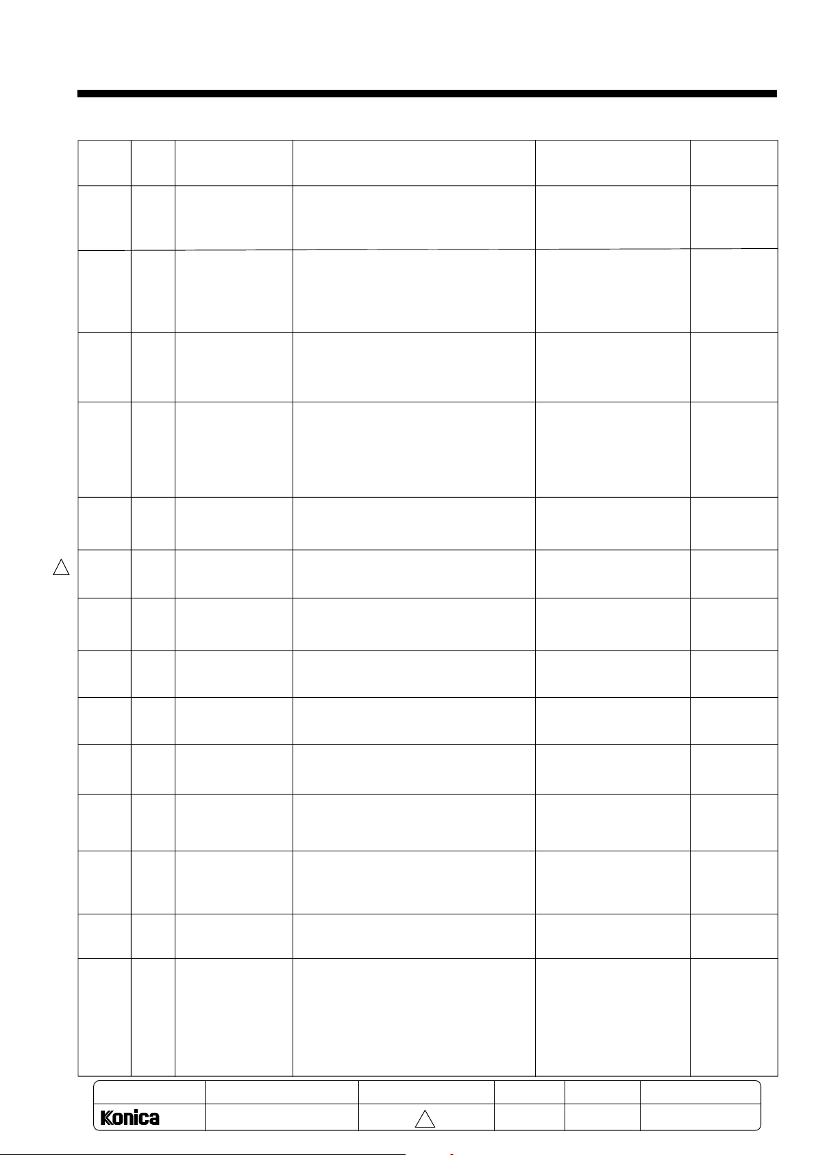
8-1. Error codes
Chapter 8 Service Functions
Order of
display
priority
1
2
3
4
5
Code
F34
F35
F36
F43
F54
Symptom
Fusing high
temperature
abnormality
Fusing low
temperature
abnormality
Fusing sensor
abnormality
AVR abnormality
Fan motor lock
Cause
* The fusing temperature exceeds the
specified temperature. (Detection
temperature = 225°C)
* The unit does not warm up even after
the set time (60 sec.) has passed from
the warm up start.
* After warming up, the fusing lamp does
not turn OFF for the specified time (30
sec.) or more.
* Fusing low temperature/thermistor
open/wire breakage.
* The temperature does not exceed -5
even after 10 sec. from the warm up
start.
* The exposure lamp error signal is ON
continuously for 15 sec. or more.
(The lamp is continuously lit, or the lamp
or temperature fuse is blown.)
* The exposure lamp does not light. (For
two seconds)
* The fan's unlock signal is detected for
two continuous seconds while the fan is
operating.
°C
Unit operation
* Copy operation impossi-
ble.
* Main unit instantaneously
stops.
* Main relay turns OFF.
* Copy operation impossi-
ble.
* Main unit instantaneously
stops.
* Main relay turns OFF.
* Copy operation impossi-
ble.
* Main unit instantaneously
stops.
* Main relay turns OFF.
* Copy operation impossi-
ble.
* Main unit instantaneously
stops.
* Main relay turns OFF.
*
Copy operation impossible.
*
Main unit instantaneously stops.
* Main relay turns OFF.
* 25-47
* Power ON/
* 25-47
* Power ON/
* 25-47
* Power ON/
* Power ON/
* Power ON/
Releasing
method
OFF
OFF
OFF
OFF
OFF
1
6
7
8
9
10
F49
F41
F42
F52
F45
SDH temperature
abnormality
Scanner return
abnormality
Scanner feeding
abnormality
Main motor drive
abnormality
Lens
drive abnormality
Developer
11
F26
initialization
abnormality
Engine section
12
F50
EEPROM
abnormality
13
P51
Upper cover
open
* When using the SDH, the platen
temperature rises to the specified
temperature.
* The Scanner HP sensor does not turn
ON even after a set time passed from
the return drive ON.
* The Scanner HP sensor does not turn
OFF even after a set time passed from
the feed drive ON.
* The unlock signal is detected for one
continuous second during the main
motor drive.
* The initialization is not completed within
a set time during the lens drive motor
drive.
* Developing unit initialization error
* Engine section EEPROM access error
* The upper cover is open.
* Instantaneous stop.
Copy operation impossible.
*
*
Main unit instantaneously stops
* Main relay turns OFF.
Copy operation impossible.
*
*
Main unit instantaneously stops
* Main relay turns OFF.
*
Copy operation impossible..
*
Main unit instantaneously stops
* Main relay turns OFF.
*
Copy operation impossible.
*
Main unit instantaneously stops
* Main relay turns OFF.
Copy operation impossible.
*
* Main unit instantaneously
stops.
* Main unit instantaneously
stops.
Copy operation impossible.
*
*
Main unit instantaneously stops.
* Power ON/
* Power ON/
* Power ON/
* Power ON/
* Power ON/
* Insialize of
Developing
unit
* Power ON/
* Close the
OFF
OFF
OFF
OFF
OFF
OFF
upper cover.
14
J32
MODEL
Fusing paper
exit jam
1312
SERVICE HANDBOOK
MANUAL
* The JAM2 sensor does not turn OFF
within 2.85 to 3.13 seconds after JAM1
sensor turned OFF. (During copying)
* Paper on the JAM2 sensor. (When
stationary)
REVISED EDITION
8-1
1
* Instantaneous stop
* The fusing heater turns
OFF.
DATA
May.1999
PAGE
8-1
* Open the
upper cover
and remove
the jammed
paper.
METHOD
REPLACEMENT
Page 3
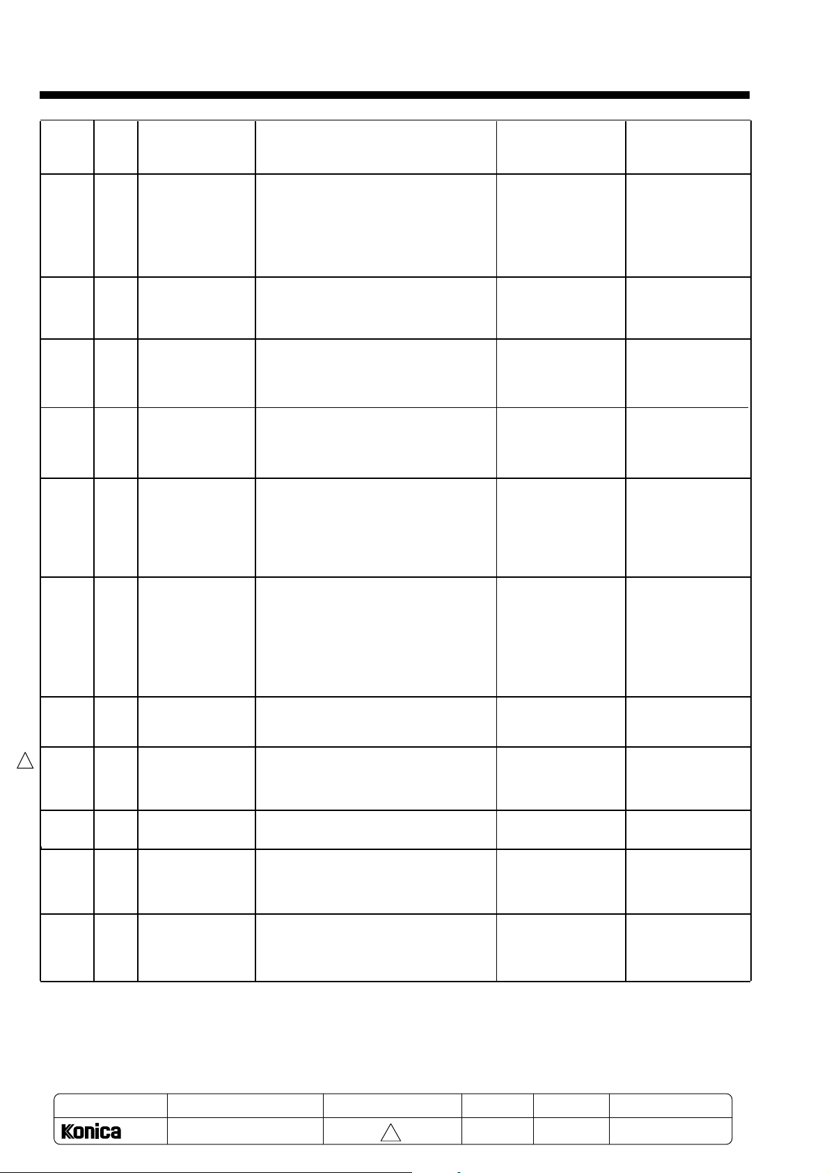
Chapter 8 Service Functions
Order of
display
priority
Code
Symptom
Cause
Unit operation
Releasing method
15
16
17
18
19
20
J16
J31
J61
J62
J11
J12
Paper feed jam
Conveyance
jam
SDH open
SDH jam
Paper feed jam
Paper feed jam
* Paper on the JAM1 sensor. (Only when
stationary)
* The JAM2 sensor (fusing paper exit
sensor) does not turn OFF within 2.85 to
3.54 sec. after the regist clutch turned
ON.
* The SDH is open while SDH is driven.
* Jam during the SDH document feed,
conveyance or exit.
* Paper is incorrectly supplied from the
unit standard cassette (upper cassette).
* The paper does not reach the JAM1
sensor within 1.30 sec. after the upper
cassette paper feed solenoid turned
ON.
* Paper is incorrectly supplied from the
operation cassette feeder (lower level).
* The paper does not reach the JAM1
sensor within 3.21 sec. after the lower
level paper feed solenoid turned ON.
* Maintains the stop
state.
* The fusing heater
turns OFF.
* Instantaneous stop
* The fusing heater
turns OFF.
* The SDH instanta-
neously stops.
* Operation stops
after the previous
paper exits.
* The SDH instanta-
neously stops.
* Operation stops
after the previous
paper exits.
*Operation stops
after the previous
paper exits.
* Operation stops
after the previous
paper exits.
* Open the jam lid on
the side of the unit,
and remove the jam
paper.
* Then, open and
close the upper
cover.
* Open the upper
cover and remove
the jam paper.
Close the SDH cover
* Remove all docu-
ments from the
SDH once.
* Open the jam lid on
the side of the unit,
and remove the jam
paper.
* Then, open and
close the upper
cover.
* Open the cassette
feeder or jam lid on
the side of the unit,
and remove the jam
paper.
* Then open and
close the upper
cover.
21
22
1
23
24
P20
P20
P26
P24
(Blink)
25
P29
(Blink)
MODEL
Drum cartridge
not mounted
Developing unit
not mounted
Developing unit
initialization
Change drum
Change
developer
MANUAL
* The drum cartridge is not installed.
* The developing unit is not installed.
* The recycle pipe is not set.
* The developing unit is not initialized.
*
This appears to indicate that the drum must
be replaced when 500 sheets have been
copied after the check drum display.
* This appears to indicate that the
developing unit must be replaced when
the toner is emptied after the check
developer display.
REVISED EDITION
DATA
* Copy operation
impossible.
* Copy operation
impossible.
* Copy operation
impossible.
* Copy operation
stops after the
previous paper
exits.
* Copy operation
stops after the
previous paper
exits.
PAGE
* Mount the drum
cartridge.
* Mount the devel-
oping unit.
* Set the recycle
pipe.
* Initialize the
developing unit.
* Replace and
initialize the drum.
* Replace and
initialize the
developing unit.
METHOD
8-2
1312
SERVICE HANDBOOK
1
May.1999
8-2
REPLACEMENT
Page 4
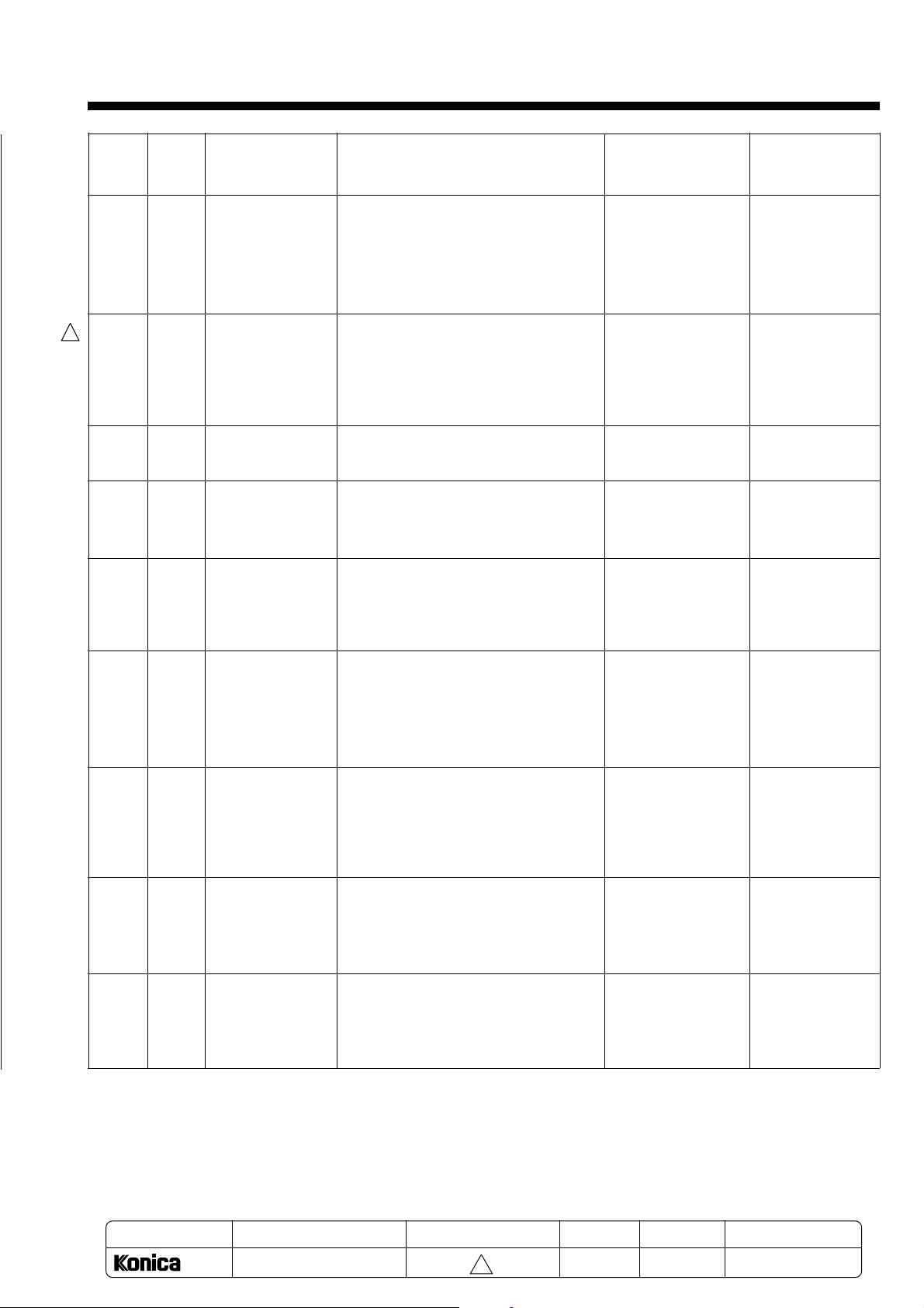
Chapter 8 Service Functions
Order of
display
priority
26 P25
1
27 P49
28
(Note 1)
29 P25
(Note 3) (Blink)
30 P27
(Note 2)
Code
Symptom
Supplying toner
Cooling SDH
Out of paper
Toner empty
Check developer/
drum
Cause
* The toner level is low.
* A document with a high black ratio was
continuously copied.
* When using the SDH, the platen section
rose to the specified temperature.
* No paper in the selected cassette.
* Toner empty
* This appears when check drum and
check developer occur simultaneously.
Unit operation
* The copy operation
is suspended. After
forced supply, the
remaining copies
are automatically
made.
* The copy operation
is suspended to cool
the unit.
* The copy operation
will resume when
the unit cools to the
specified temperature.
* Copy operation
stops after the
previous paper exits.
* After copying 30
sheets, copy
operation stops
according to the
toner empty.
* This is only a
display. The copy
operation will
continue.
Resetting
method
* Automatically
reset.
Note when there
is no toner left in
the core, Toner
empty (P25 blink)
will appear.
* Automatically
reset.
* Supply paper.
* Supply toner.
* If the change
developer or
change drum
display appears,
follow the instructions.
31 P24
(Note 2)
32 P29
(Note 2)
33 P11
(Note 3)
34 P12
(Note 3)
Check drum
Check developer
Upper cassette
paper size error
Lower cassette
paper size error
* This indicates that the No. of copies
made by the drum has reached 24500
sheets, and the drum replacement
interval is nearing.
* This indicates that the No. of copies
made with the developer has reached
25000 sheets, and the developer
replacement interval is nearing.
* The size setting for the upper cassette is
incorrect.
* The size setting for the lower cassette
is incorrect.
* This is only a
display. The copy
operation will
continue.
* This is only a
display. The copy
operation will
continue.
*
After the copy
operation is completed, a warning will
appear. However, the
copy operation is not
be prohibited.
*
After the copy
operation is completed, a warning will
appear. However, the
copy operation is not
be prohibited.
* When the change
drum display
appears, replace
and initialize the
drum.
* When the change
developer display
appears, replace
and initialize the
developing unit.
* Set the correct
size for the upper
cassette.
* Set the correct
size for the lower
cassette.
(Note 1) This is not displayed by the code.The cassette LED will blink.
(Note 2) This appears at Auto Clear or when the power is turned ON. The error display will go out when the nu-
meric keys, Stop key or Copy key are pressed.
(Note 3)
This is displayed again at Auto Clear or when the power is turned ON after the copy operation is completed.
The error display will go out when the numeric keys, Stop key or Start Print key are pressed.
MODEL
1312
MANUAL
SERVICE HANDBOOK
REVISED EDITION
8-3
1
DATA
May.1999
PAGE
8-3
METHOD
REPLACEMENT
Page 5
Chapter 8 Service Functions
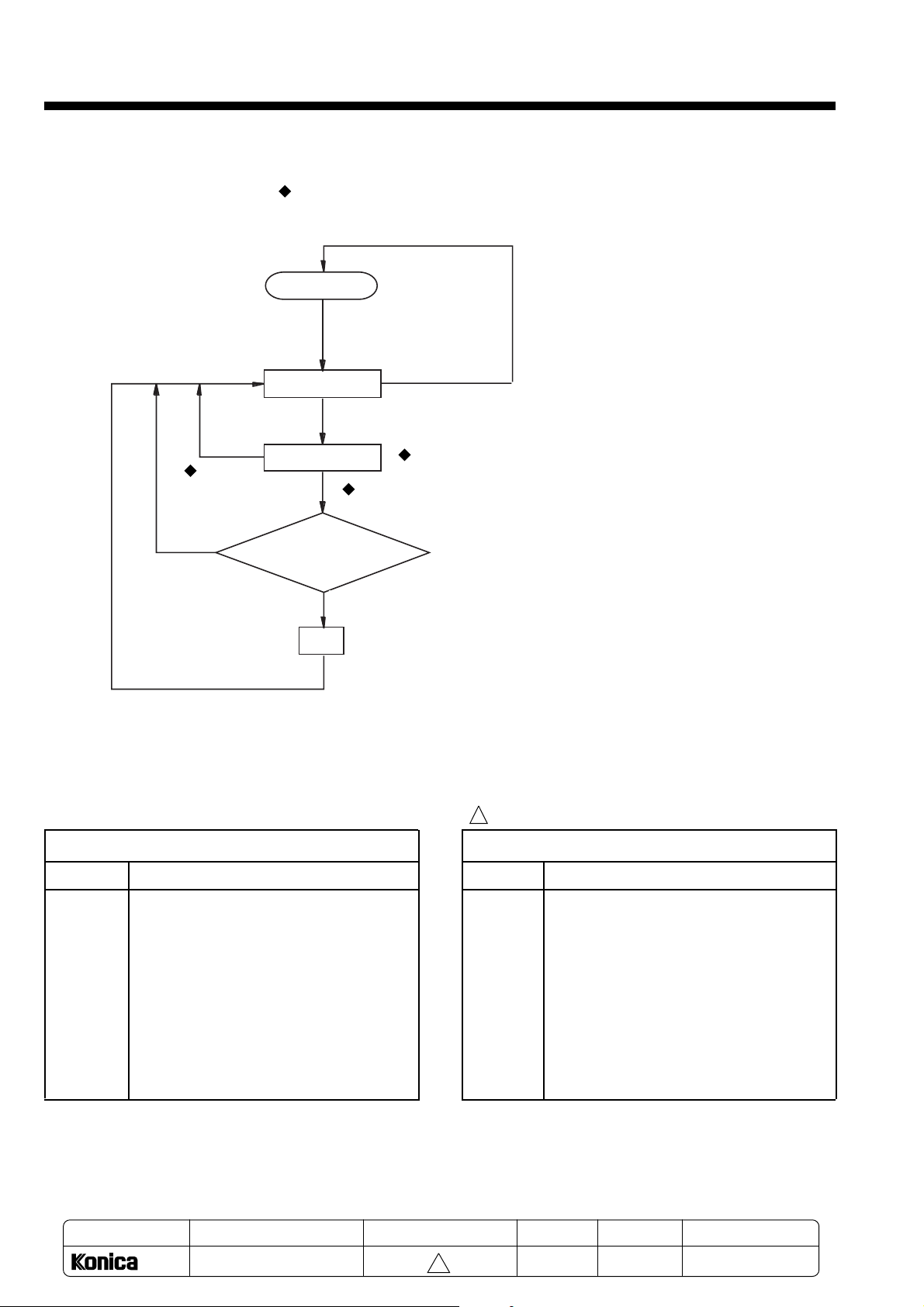
8-2. User setting mode
8-2-1. Setting procedure
: Indicates key operation.
Return to Auto Clear state
Standby
Press the
"Select Paper"
key for 5 sec.
Setting default
state
Stop key
Input the
Stop key
NO
setting values
Start Print
Valid number?
YES
Set
Setting completed.
Note 2: The “Magnification”, “Enlarge”, “Reduce” and “Select Paper” keys are invalid in this mode.
Note 3: Auto Clear and Power Save operations are invalid in this mode.
8-2-2. Setting item list
C-00 to C-09: Standard cassette paper size setting
Item No.
Details
Input a 2-digit number with
the numeric keys.
Note 1:The key operation is ignored if press the "Start
Print" key after the input of the 1-digit number.
1
Option cassette paper size setting
Item No.
Details
C-00 LT
C-01 LG
C-02 A4
C-03 B5
C-04 A5
C-05 F4-1: 8X13"(203X330mm)
C-06 F4-2: 8.5X13"(216X330mm)
C-07 F4-3: 8.25X13"(210X330mm)
C-08 F4-4: 206X337mm
C-09 -
MODEL
1312
SERVICE HANDBOOK
MANUAL
C-10 LT
C-11 LG
C-12 A4
C-13 B5
C-14 A5
C-15 F4-1: 8X13"(203X330mm)
C-16 F4-2: 8.5X13"(216X330mm)
C-17 F4-3: 8.25X13"(210X330mm)
C-18 F4-4: 206X337mm
C-19 -
REVISED EDITION
8-4
1
DATA
May.1999
PAGE
8-4
METHOD
REPLACEMENT
Page 6

Chapter 8 Service Functions
C-20 to C29:
Item No.
C-20
C-21
C-22
C-23
C-24
C-25
C-26
C-27
C-28
C-29
1
C-30 to 33: Auto reset time
Item No.
C-30
C-31
C-32
C-33
30 sec.
60 sec.
90 sec.
120 sec.
C-34
C-35
C-36
C-37
C-38
C-39
Details
Details
(Default)
C-50 to C51: Initialization
Item No.
C-50
C-51
Drum initialization (Note 1)
Developer initialization (Note 2)
Details
C-52
C-53
C-54
C-55
C-56
C-57
C-58
C-59
C-60 to C62: Automatic paper length check
Item No.
C-60
C-61
C-62
OFF (Note 3)
ON (Note 4)
ON (Default) (Note 5)
Details
C-63
C-64
C-65
C-66
C-67
C-68
C-69
C-40 to C-42: Counter read
1
Item No.
C-40
C-41
C-42
Total counter read
Drum counter read
Developer counter read
Details
C-43
C-44
C-45
C-46
C-47
C-48
C-49
The display for each counter is displayed in the order
of 3 high-order digits (3 sec.), blank (1 sec.) and 3
low-order digits (3 sec.)
(Note 1) Aging the drum and reset the drum counter.
(Note 2) Adjust the L detection data and reset the
developer counter.
(Note 3) The side erase lamp is controlled with the
user registered paper size.
(Note 4) The side erase lamp at the first copy is
controlled with the user registered paper size
during continuous copies. From the second
copy, it is controlled with the detected paper
size at the first copy. The paper size is detected with the paper passing time on JAM1
sensor.
(Note 5) The side erase lamp at the first copy is
controlled with LT size during the continuous
copies. From the second copy, it is controlled
with the detected paper size at the first copy.
The paper size is detected with the paper
passing time on JAM1 sensor.
MODEL
1312
MANUAL
SERVICE HANDBOOK
REVISED EDITION
8-5
1
DATA
May.1999
PAGE
8-5
METHOD
REPLACEMENT
Page 7

Chapter 8 Service Functions
8-3. Service mode
8-3-1. Entering the service mode
The destination display appears during and after transition to the service mode.
Standby state display
Note 1: The “Magnification”, “Enlarge” and “Select Paper” keys are
US destination display
Japan destination display
Europe destination display
Input the numeric key “0”
within 2 sec.
invalid during transition to the service mode. (These are valid after
the service mode is entered.)
Note 2: Auto Clear and Power Save operations are invalid in this
mode.
Standby state
Press the "Enlarge" key and "Reduce" key for 5
sec. in the Scale 1: 1 mode, the local distination is
displayed.
NO
Includes an input other
than “0”.
YES
: Indicates key operation.
Stop key
Stop key
25 Mode default
setting state
Data setting
25 Mode
operation
Enter operation
Stop key
NO
25
Stop key
Service mode default state
Select service mode
Start Print key
Valid No.
YES
What is the input
value?
36
36 Mode default
setting state
Test/adjustment
setting
36 Mode
operation
36
Enter operation
Stop key
Input a valid mode No. using the numeric keys.
(The valid mode Nos. are 25, 36, 47.)
47
47 Mode default
setting state
Input/output
control setting
Stop key
47 Mode
operation
Enter operation
Operation completed
Operation completed
8-6
Operation completed
Page 8

8-3-2. 25 mode
25 mode is used to change the data written in the involute memory.
Operation example: To change the address 35 data. (Example: 6 ->5)
Standby state display
Chapter 8 Service Functions
: Indicates key operation.
Destination display
State with 25 mode elected
25 Mode address input wait
Example: State with address
35 selected
Example: Data already registered
Example: State with data changed
Stop key
Standby state
Service mode default state
Select service mode
Stop key
25 Mode
Select non-volatile
memory address
Return to Auto Clear state.
Press the "Enlarge" key and "Reduce" key for 5 sec.
in the Scale 1: 1 mode, and press the 0 key within 2
sec. after the local destination displayed.
Stop key
Input 25 with the numeric keys
Start Print key
Stop key
Input 2-digit address with the numeric keys
Start Print key
Non-volute data display
Non-volatile data change
Input 5 with the numeric keys
Start Print key
8-7
Page 9

Chapter 8 Service Functions
25 mode list
1
1
1
Address
20
30
32
33
34
35
36
37
39
40
41
42
43
44
47
Details
Setting for time to enter power save mode (spare)
1: Address 62 setting takes precedence
2: OFF
3: 60 min.
4: 120 min.
5: 240 min.
Destination setting (Note 1)
1:Japan (Fixed scale: Japan, paper size default setting: A4)
2: US (Fixed scale: US, paper size default setting: LT)
3: Europe (Fixed scale: Europe, paper size default setting: A4)
Total counter setting (105)
Total counter setting (104)
Total counter setting (103)
Total counter setting (102)
Total counter setting (101)
Total counter setting (100)
Drum counter setting (105)
Drum counter setting (104)
Drum counter setting (103)
Drum counter setting (102)
Drum counter setting (101)
Drum counter setting (100)
Reset fusing error (Reset by inputting "0", and turning power ON/OFF.)
Fusing high temperature error (F34) detection (hardware)
Fusing sensor error (F36) detection (hardware)
Fusing high temperature error (F34) detection (software)
Fusing low temperature error (F35) detection (software)
Fusing sensor error (F36) detection (software)
Setting value
1 to 5 (default: 1)
1 too 3 (default:3)
0 to 9
0 to 9
0 to 9
0 to 9
0 to 9
0 to 9
0 to 9
0 to 9
0 to 9
0 to 9
0 to 9
0 to 9
0 (default)
1
3
4
5
6
62
1
Setting for time to enter power save mode (normal use)
1: 30 min.
1 to 3 (default: 1)
2: 2 min.
3: 5 min.
80
Fusing temperature control setting 1: 182 ˚C
1 to 5 (default: 3)
2: 185 ˚C
3: 188 ˚C
4: 190 ˚C
5: 193 ˚C
81
User/service selection setting for drum initialization and developer
1 to 2 (default: 1)
initialization
1: Released to user
2: Only service mode (47 mode) valid
84
1
Toner density control setting 1: 5.5%
1 to 5 (default: 3)
2: 6.0%
3: 6.5%
4: 7.0%
5: 7.5%
85
86
87
1
88
89
90
Developer count setting (105)
Developer count setting (104)
Developer count setting (103)
Developer count setting (102)
Developer count setting (101)
Developer count setting (100)
0 to 9
0 to 9
0 to 9
0 to 9
0 to 9
0 to 9
(Note 1) Fixed scale Japan: B5>A4(115%), B4>A4(82%), B4>B5(71%)
US: 5.5
x
8.5>8.5
x
11(129%), 8.5
x
14>8.5
x
11(77%)
Europe: A5>A4(141%), B4>A4(82%), A4>A5(71%)
MODEL
MANUAL
REVISED EDITION
8-8
1312
SERVICE HANDBOOK
1
May.1999
DATA
PAGE
8-8
METHOD
REPLACEMENT
Page 10

Chapter 8 Service Functions
8-3-3. 36 mode
36 mode is used to carry out the running test and to make various adjustments.
(Note) When doing the running test, close the upper cover. If the upper cover is open, the developing unit will be
locked, or the scanner operation failure will occur.
Operation example: To carry out AVR adjustment (address 90) of the equal magnification MIN. position.
Standby state display
Destination display
State with 36 mode selected
36 mode code input wait
Example: State with code
90 selected
Example: The data already
registered brinks
Stop key
Stop key
Return to Auto Clear state.
Standby state
Press the "Enlarge" key and "Reduce" key for 5 sec.
in the Scale 1: 1 mode, and press the 0 key within 2
sec. after the local destination displayed.
Service mode default state
Select service mode
Start Print key
36 Mode
Select adjustment mode
: Indicates key operation.
Stop key
Input 25 with the numeric keys
Input code (example: 90) with numeric keys
Example: The changed data blinks
Example: State with changed
data entered
Adjustment data change mode
Adjustment data change
Adjustment data enter
Copy operation
8-9
Page 11

Chapter 8 Service Functions
36 mode list
Code
01
02
10
11
12
13
14
40
1
1
41
86
87
88
89
90
Details
No paper copy running (Mechanical counter: No count up)
Copy running test (Mechanical counter: No count up)
x100 copy running test (Mechanical counter: Count up)
No paper copy running test (Mechanical counter: Count up)
x100 no paper copy running test (Mechanical counter: Count up)
Intermittent copy running test (Mechanical counter: Count up)
Intermittent copy + no paper copy running test (Mechanical counter: Count up)
Paper leading edge transfer start timing adjustment
Adjustment range: Approx. +9 ~ -13mm
Paper trailing edge transfer end timing adjustment
Adjustment range: Approx. +15 ~ -7mm
AVR adjustment 1 Enlargement center (Light amount adjustment)
Adjustment range: Approx. 43V ~ 67V
AVR adjustment 2 Reduction center (Light amount adjustment)
Adjustment range: Approx. 43V ~ 67V
AVR adjustment 3 Life size Max. (Light amount adjustment)
Adjustment range: Approx. 55V ~ 80V
AVR adjustment 4 Life size Center (Light amount adjustment)
Adjustment range: Approx. 43V ~ 67V
AVR adjustment 5 Life size Min. (Light amount adjustment)
Adjustment range: Approx. 30V ~ 55V
1
Adjustment range
01 to 64
01 to 64
01 to 64
01 to 64
01 to 64
01 to 64
01 to 64
91
Copy leading edge timing (Paper feed timing adjustment)
01 to 64
Adjustment range: Approx. ±5mm
1
92
Image leading edge erase
01 to 64
Adjustment range: Approx. ±10mm
93
Scanner speed adjustment (Vertical magnification adjustment)
01 to 64
Adjustment range: Approx. ±6 mm in respect to A4 length
95
Lens home position adjustment (Horizontal magnification adjustment)
01 to 64
Adjustment range: Approx. ±6mm in respect to A4 width
96
SDH copy leading edge timing(Document feed timing adjustment)
01 to 64
Adjustment range: Approx. ±5mm
97
SDH scanner speed adjustment (Vertical magnification adjustment)
01 to 64
Adjustment range: Approx. ±6mm in respect to A4 length
1
98
Image trailing edge erase
01 to 64
Adjustment range: Approx. ±10mm in respect to default setting
Note 1: The Enlarge, Scale and Reduce mode is apply for codes 91 and 96.
Note 2: For codes 02 and 10, if the original is set to theSDH and operation is started, the SDH copy operation
will take place. (No. of copies setting is invalid.)
Note 3: For codes 01, 11 and 12, if the SDH original sensor is turned ON and operation is started, no paper
operation will also take place with the SDH.
MODEL
1312
MANUAL
SERVICE HANDBOOK
REVISED EDITION
8-10
1
DATA
May.1999
PAGE
8-10
METHOD
REPLACEMENT
Page 12

Chapter 8 Service Functions
8-3-4. 47 mode
47 mode is used to check the input and output. The operation of each electrical part can be confirmed. This mode
is also used to initialize the drum, developer and settings.
Operation example: To carry out the JAM2 sensor check (code 22).
: Indicates key operation.
Standby state display
Return to Auto Clear state.
Destination display
Standby state
47 Mode code input wait
Example: State with code
22 selected
JAM2 sensor
"OFF"
JAM2 sensor
"ON"
Stop key
Stop key
Press the "Enlarge" key and "Reduce" key for 5 sec.
in the Scale 1: 1 mode, and press the 0 key within 2
sec. after the local destination displayed.
Service mode default state
Select service mode
Start Print key
47 Mode
Input code (example: 22) with numeric keys.
Input the input/output code
Start Print key
Output
operation
Input 47 with the numeric keys
Stop key
Stop key or end of operation
8-11
Page 13

Chapter 8 Service Functions
Mode 47 list
Code
00
01
1
02
1
03
1
04
1
20
22
30
JAM1 sensor input
JAM2 sensor input
Mirror HP sensor input
31
32
Lens HP sensor input
41
Input details
Output details
Exposure lamp continuous lighting (Mirror moves to shipping
position after lit for 6 sec.)
Toner motor forced rotation mode (Stops after 4 sec. )
High voltage output (Adjustment not possible) (Charging) (Stops
after 1 min. output)
High voltage output (Adjustment not possible) (Transfer +)
(Stops after 1 min. output)
High voltage output (Adjustment not possible) (Transfer -) (Stops
after 1 min. output)
Scanner running mode (Optical reciprocation drive) (Stops with
Stop key)
Developing unit running mode (Steps after 1 min.)
42
43
Cooling fan high-speed rotation (5 sec.)
Mechanical counter, count up (Counts one with each press of
Start Print key)
48
49
69
91
92
93
ROM version read (After once Start
Print key press)
All LEDs on the operation panel light (After two Start Print key
presses) (Note 1)
All side erase lamps light (Goes out after 3 sec. or Stop key)
SDH scanner running mode
Drum initialization(Aging the drum and reset the drum counter)
Setting initialization (initial reset) (Note 2)
Developer initialization(Adjust the L detection data and reset the
developer counter)
Note 1: When the Start Print key is pressed after inputting code 48, first the ROM version displays. When the Copy
key is pressed again, the 7-segment LED and all LEDS on the other operation panels light.
ROM version display
Example: Ver. 1.07
All light
Start Print Key
Note 2: Initializied data
"Cassette paper size data", "Time data to enter Power save mode", "Auto clear time data", "Counter value",
Drum counter value", "Developer counter value"," Developer initialization data","Fusing temperature selection data" are initializied.
MODEL
MANUAL
REVISED EDITION
DATA
PAGE
METHOD
8-12
1312
SERVICE HANDBOOK
1
May.1999
8-12
REPLACEMENT
Page 14

Chapter 8 Service Functions
8-4. Backup data
The following data is backed up in the non-volatile
memory (EEPROM) on the main CB(unit main).
1
Data item
Cassette paper size(U)
Cassette paper size(L)
Time to enter power save mode
Auto clear time
Total counter value
Drum counter value
Developer counter value
Image leading edge timing value
Image leading edge erase
amount adjustment value
Image trailing edge erase amount
adjustment value
AVR adjustment value
Developer initialization data
(L detection data)
Toner density control selection
value
Fusing temperature control
selection value
Scanner speed adjustment value
Lens unit home position adjustment value
SDH copy leading edge timing
value
SDH speed adjustment value
Destination setting value
Setting method
User setting mode
C-00~08
User setting mode
C-10~18
25 mode: 20
User setting mode
C-30~33
25 mode: 32 to 37
25 mode: 39 to 44
25 mode: 85 to 90
36 mode: 91
36 mode: 92
36 mode: 98
36 mode: 86 to 90
Re-initialization
25 mode: 84
25 mode: 80
36 mode: 93
36 mode: 95
36 mode: 96
36 mode: 97
25 mode: 30
Note 2: When the paper length is from 314mm to 347
mm, if the paper size set with the cassette
paper setting and the detected paper size
differ, an error code (P11, P12) will appear.
Note 3: When the paper size error code does not
appear, the detected paper size will be detected. (The cassette paper setting’s paper
size will be reset.)
1st copy operation
Determine as
jam
Standby state
Set the document
Set the No. of copies, and start copying
Paper length is
automatically detected
Paper length 234mm?
Paper length 268mm?
Paper length 288mm?
Paper length 314mm?
Paper length 347mm?
NO
Paper length 370mm?
2nd and following copy operation
End of copy operation
Example: To make 18 copies
<
=
NO
<
=
NO
<
=
NO
<
=
NO
<
=
NO
<
=
YES
YES
YES
YES
YES
YES
Input 18 with the numeric keys,
and press the Copy key
Determine as A5, and copy.
Determine as B5, and copy.
Determine as LT, and copy.
Determine as A4, and copy.
Determine as F4 size, and copy.
Determine as LG, and copy.
8-5. Automatic paper size detection
When the automatic paper size detection is selected
with the user setting mode (C-61, 62), the paper
length will be automatically checked by JAM 1 sensor.
Note 1: The paper length is detected during the first
copy operation, so the 1st copy time will not
satisfy 12CPM.
(When feeding from lower cassette.)
MODEL
1312
MANUAL
SERVICE HANDBOOK
REVISED EDITION
8-13
1
DATA
May.1999
PAGE
8-13
METHOD
REPLACEMENT
Page 15

Chapter 8 Service Functions
8-6. General operation mode
Power ON
Warming up
Key input
Power save mode
Press the "Enlarge" key and "Reduce" key for 5 sec. in the Scale 1: 1
mode, and press the 0 key within 2 sec. after the local destination
displayed.
2, 5, "Start Print" key
3, 6, "Start Print" key
25 mode
* Writing of
non-volatile memory
Service mode
Stop key Stop key
Stop key
36 mode
* Running test
* Adjustment
Stop key
4, 7, "Start Print" key
47 mode
* Input check
* Output check
Standby mode
(User mode)
Press "Select Paper"
key for 5 sec.
User setting mode
* Cassette paper size setting
* Clear timer setting
* Counter value read
Power save timeout
Setting end
8-14
 Loading...