

Page 1

●
Failure to operate the machine correctly could result in malfunction or accidents,so please
read this manual carefully before commencing operation. Be sure to operate the machine as
described in this manual.
●
Keep this manual carefully so as to be ready for use when necessary.
Page 2
73
Thank you for purchasing this KONAMI product. This manual explains how to operate your
game machine correctly and safely.
About this product
•Failure to operate the machine correctly could result in malfunction or
accidents, so please read this manual carefully before commencing
operation. Be sure to operate the machine as described in this manual.
•Keep this manual carefully so as to be ready for use when necessary.
•If the machine still fails to display or to get started, immediately turn OFF
the main power switch, unplug the power cord from the receptacle and
contact your nearest dealer .
•This manual covers the following models:
•GQ830-TB •GQ830-SD
•GQ830-HD
The specifications of GQ830-TB may be somewhat different from GQ830-SD and GQ830-HD.
In such a case, read the descriptions of the model which applies to the game machine you
are operating.
•The specifications of this product are subject to change without notice for
reasons such as improving the performance.
•The contents of this game, its main devices and design are protected under each law
concerning patent, copyright and other intellectual properties.
•Unauthorized reproduction of this document or any of its contents is strictly
forbidden.
© 1999 KONAMI ALL RIGHTS RESERVED.
Driver software used under license of 3Dfx interactive.
Page 3
741
Contents
Precautions for use .................................................................................. 2
....................................................................................................................... 10
Locations of warning and other safety labels ....................................... 7
............................................................................. 15
Specifications........................................................................................... 8
....................................................................................................................... 16
2 Names of parts........................................................................................ 18
3 How to play ............................................................................................. 19
4 Opening and closing the doors
4-1 Opening and closing the maintenance door......................................... 20
4-2 Opening and closing the coin door....................................................... 21
4-3 Opening and closing the monitor adjustment door............................... 22
5 Game settings
5-1 Checking the game performance........................................................ 23
5-2 Setting and adjustment of game mode ............................................... 24
5-3 Mode descriptions.............................................................................. 25
6 Installation and assembling
6-1 Fastening the adjusters.......................................................................34
6-2 Installing the step cover ...................................................................... 35
6-3 Installing the title unit .......................................................................... 36
6-4 Service panel ...................................................................................... 36
6-5 Power unit ........................................................................................... 37
6-6 Separating the machine ...................................................................... 38
6-7 Moving the coin counter...................................................................... 41
7 Maintenance
7-1 Replacing the coin selector................................................................. 42
7-2 Replacing the fluorescent light............................................................ 43
7-3 Replacing the start button................................................................... 44
7-4 Replacing the rifle unit ........................................................................ 46
7-5 Replacing the rifle unit microswitch..................................................... 47
7-6 Replacing the scope ........................................................................... 48
7-7 Replacing the rifle unit potentiometers................................................ 49
7-8 Taking out the PCB unit....................................................................... 53
7-9 Resetting the circuit protector ............................................................. 55
7-10
Adjusting the monitor.......................................................................... 56
7-11
Adjusting the brightness on the scope LCD screen ........................... 57
7-12
Troubleshooting .................................................................................. 58
8 Annex
8-1 Label locations and exploded view ..................................................... 62
8-2 Wiring diagram.................................................................................... 73
Page 4
2
Precautions for use
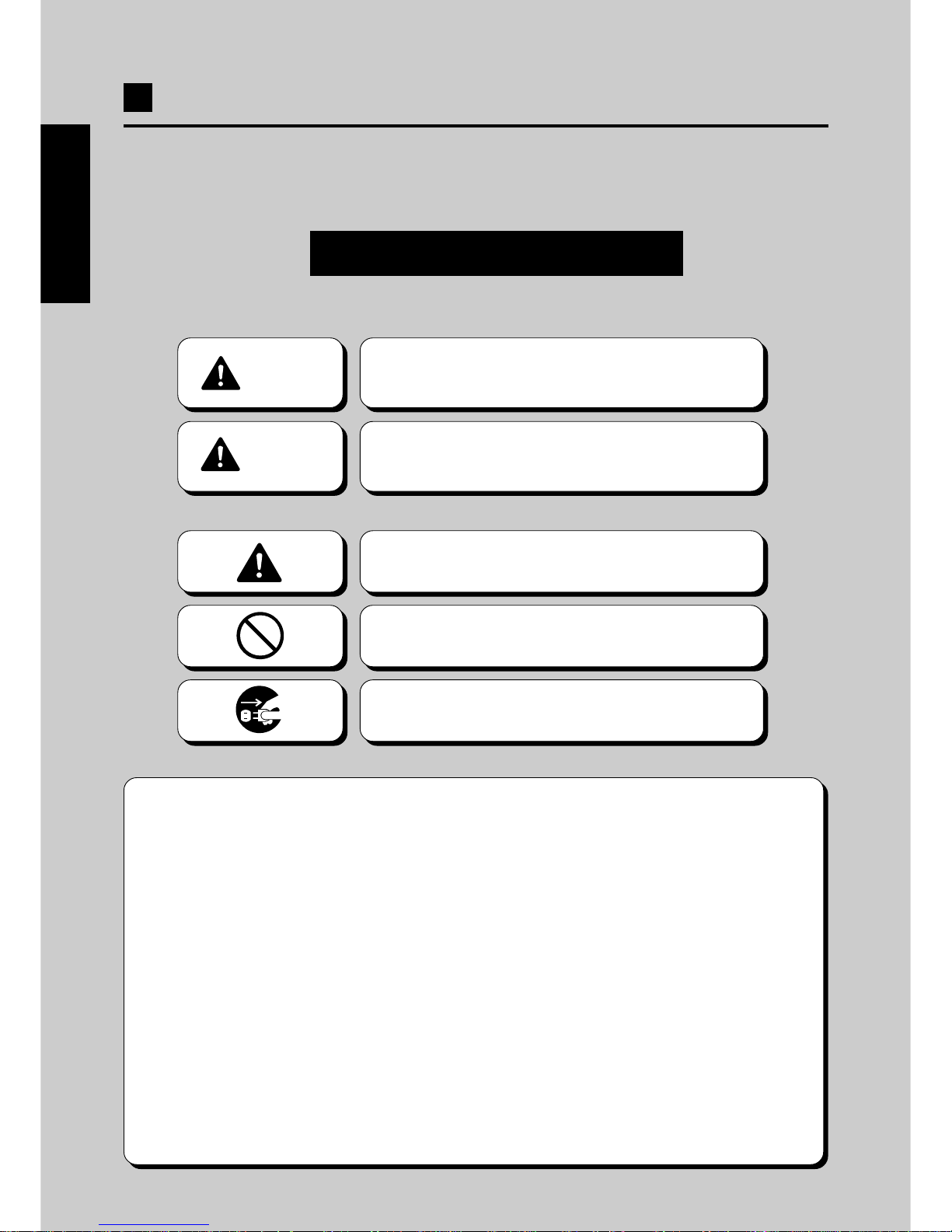
Be sure to read the following
•The following suggestions show the degree of danger and damage caused when the
product is used improperly with the suggestions disregarded.
•The following graphic suggestions describe the types of precautions to be followed.
Indicates a matter of which care should be taken.
Indicates a matter which is forbidden.
Indicates a matter which should be performed
without fail.
2
CAUTION
Indicates a situation where disregarding the
suggestions could result in injury or product
damage.
WARNING
Indicates a situation where disregarding the
suggestions could result in death or serious
injury.
•In this instruction manual, some procedures require a qualified in-shop maintenance person or
industry specialist. For such instructions, a qualified person must take care of the jobs.
·Otherwise an electric shock, machine trouble, or a serious accident may result.
·Replacing the machine parts, inspecting and maintaining the machines, and troubleshooting must be
assigned only to a qualified in-shop maintenance person or industry specialist. This booklet gives
instructions that hazardous jobs in particular must be handled by an industry specialist. Qualified
in-shop maintenance persons and industry specialist are defined as follows.
Qualified in-shop maintenance persons
·A qualified in-shop maintenance person must have experiences in maintaining amusement machines,
money changers and the like. Under the supervision of an amusement machines shop owner or
manager, he or she routinely assembles, installs, inspects and maintains the amusement machines, or
replaces their component units and consumable parts, in the amusement machines workshop and/or
shop.
Jobs handled by qualified in-shop maintenance persons
·Assembling, installing, inspecting and maintaining amusement machines and money changers, and
replacing their component units and consumable parts.
Industry specialist
·An industry specialist must be engaged in designing, manufacturing, inspecting and servicing amusement
machines. Or he or she must have an education in electrical, electronic and mechanical engineering,
and routinely maintain and repair amusement machines.
Jobs handled by industry specialist
·Assembling and installing amusement machines and money changers, and repairing and adjusting
their electrical, electronic and mechanical component parts.
•
Definitions of qualified in-shop maintenance persons and industry specialist who handle this product.
ENGLISH
The following safety precautions are given throughout this manual. They must be strictly
followed to protect those who install, use or maintain this product as well as to prevent other
people’s injuries and property damages.
Page 5
3
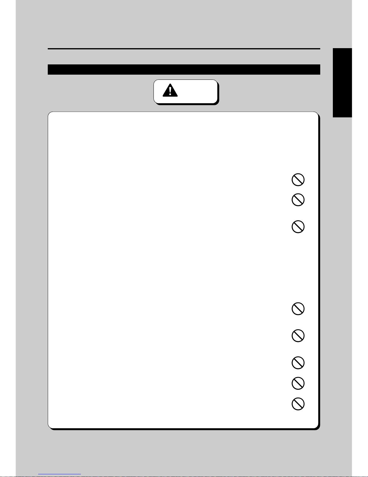
•Be sure to consult your nearest dealer when setting up, moving or transporting this product.
·This product should not be set up, moved or transported by anyone other than industry specialist.
Doing so could result in injury or product damage.
·When installing this product, set the 6 adjusters stable on the floor and make sure that the product is
installed stably in a horizontal position. Unstable installation may result in injury or accident.
·When installing this product, use case not to apply undue force to opening and closing parts and other
movable parts. Otherwise, injury or accident may result, or the product may be damaged.
•This product is an indoor game machine. Never set up the game machine outside.
·Setting up this product outside could result in accidents or equipment failure.
•Do not set up the game machine near emergency exits.
·Doing so could block exits in time of emergency and could result in death or serious
injury.
•Do not set up the game machine.
·Otherwise an accident or malfunction may result.
·In a place exposed to rain or moisture.
·In a place exposed to direct sunlight.
·In a place exposed to direct heat from air-conditioning and heating equipment, etc..
·Near hazardous flammable substance such as thinner and kerosene.
·On an inclined or uneven floor.
·Near fire extinguishing equipment.
·In a place exposed to strong vibration.
·In a place exposed to excessive dust.
·Near equipment generating strong magnetism or electric waves.
•Do not place containers holding chemicals or water on or near the game machine.
·Electrical shock or damage could be caused by water or foreign matter entering the
inside of the machine.
•Do not place objects near the ventilating holes.
·Doing so could cause the internal temperature to rise excessively, resulting in fire or
equipment failure.
•Do not bend the power cord by force or place heavy objects on it.
·Doing so could result in electric leakage or fire.
•Never plug or unplug the power cord with wet hands.
·Doing so could result in electrical shock.
•Never unplug by pulling the power cord.
·Doing so could damage the cord, resulting in electric leakage or fire.
Precautions for use
3
WARNING
ENGLISH
Setting Up
Page 6
4
•Be sure to use indoor wiring for within the specified voltage range. For extension
cord, use indoor wiring of the specified rating or more.
·Failure to do so could result in fire or equipment failure.
•Be sure to use the attached power cord.
·Otherwise a fire or machine trouble may result.
•Never plug more than one cord at a time in the electrical receptacle.
·Doing so could result in fire or electrical shock.
•Do not lay the power cord where people walk through. Y ou may tread on or stumble
over them.
·You may stumble down and get injured, or damage the power cord.
•Be sure to ground this product.
·Otherwise an electric shock or machine trouble may be caused.
•Do not apply a strong force for moving the machine.
·Otherwise, it may result in an accident or breakage of the units.
•Do not hold the rifle unit when moving the machine.
·Otherwise, it may result in an injury or damage to this product.
•Clearance of 100 mm (3.94in) or more should be created between the game
machine and walls.
·Otherwise the machine (s) cannot be ventilated well, resulting in malfunction.
•Do not change the DIP switch setting of this product to other than factory setting.
·Otherwise, the game can not be played properly.
Setting Up
4
Precautions for use
CAUTION
Operation
WARNING
•If there is any abnormality such as smoke, bad smell or abnormal noise being
emitted from the machine, immediately turn OFF the main power switch and unplug
the power cord from the receptacle to stop operating it.
·Using the machine in abnormal conditions could result in fire or accidents.
In case of abnormality
1 Turn OFF the main power switch.
2 Unplug the power cord from the receptacle.
3 Contact your nearest dealer.
•Do not leave the power cord plugged improperly or covered with dust.
·Doing so could result in electrical shock or fire, so inspect the power cord periodically.
ENGLISH
Page 7

5
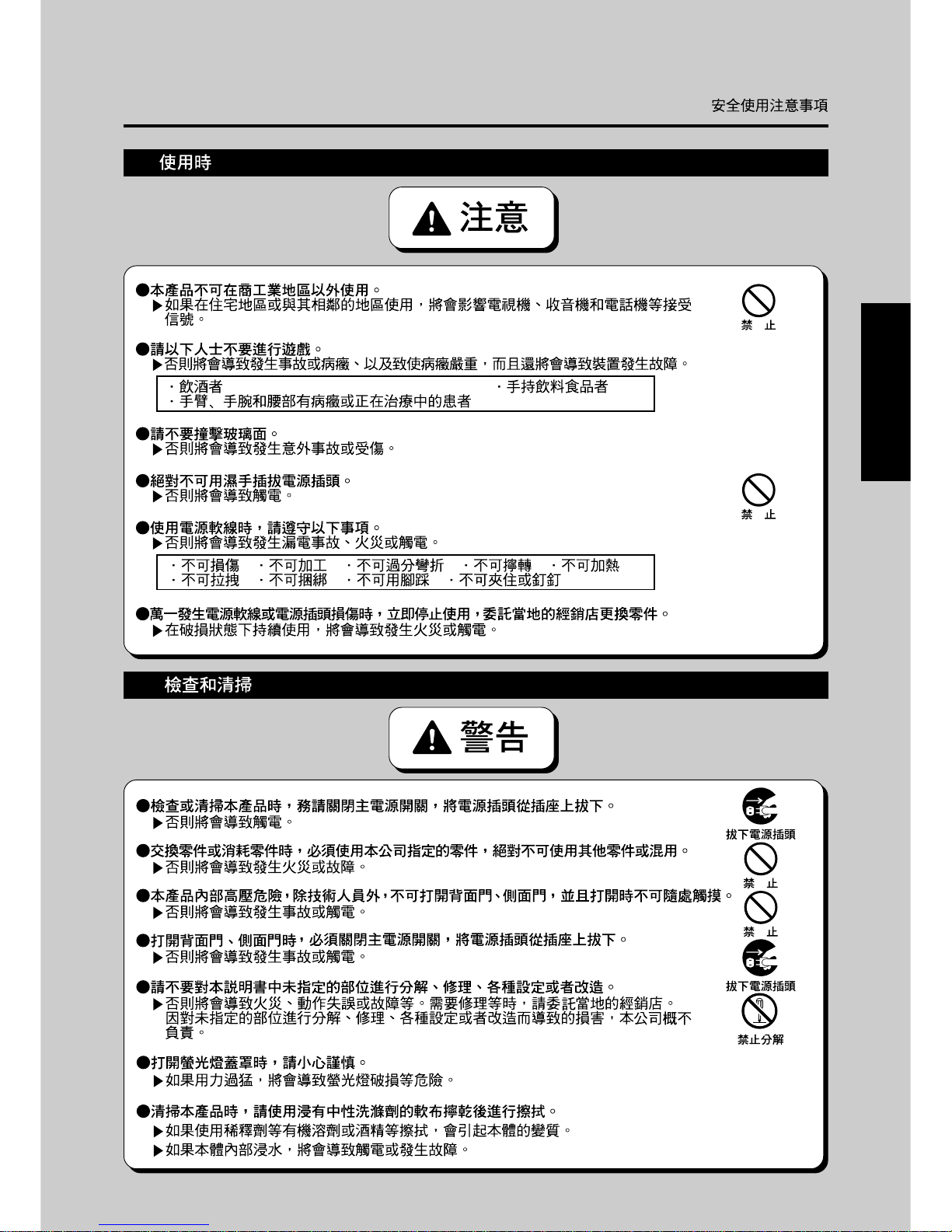
•Do not use this product anywhere other than industrial areas.
·Using in a residential area or an area next to a residential area could affect signal reception
of radios, television sets, telephones, etc..
•The following users should not play the game.
·Doing so could cause accidents or illness.
·Those under the influence of alcohol. ·Those with drink and / or food in hand.
·Those suffering from or being treated for arm, wrist or small - of - the back ailments.
•Do not give impact to the glass cover.
·Otherwise, it may result in an unexpected accident or injury.
•Do not plug or unplug the power cord with wet hands.
·Doing so could result in electrical shock.
•In handling the power cord, follow the instructions below.
·Otherwise an electric leak, fire or electric shock may result. Normal communication play
may also be impossible.
·Do not damage the power cord. ·Do not modify the power cord.
·Do not bend the power cord excessively . ·Do not twist the power cord.
·Do not heat the power cord. ·Do not pull the power cord.
·Do not bind the power cord. ·Do not tread on the power cord.
·Do not sandwich the power cord. ·Do not drive a nail into the power cord.
•If the power cord or power plug becomes damaged, stop using the machine immediately
and ask your nearest dealer to replace the parts.
·Using a damaged power cord or power plug could result in fire or electrical shock.
•Be sure to turn OFF the main power switch and unplug the power cord from the
receptacle before inspecting or cleaning the machine.
·Failure to do so could result in electrical shock.
•When replacing parts, be sure to use parts of the correct specifications. Never use
parts other than the specified ones.
·Using improper parts could result in fire or equipment failure.
•There are high-voltaged parts inside the product. Other persons than qualified industry
specialist should not open the back door and side door. When the back door and side
door is opened, pay due attention not to touch the inside unnecessarily.
·Otherwise an accident or electric shock may result.
•When opening the back door and side door, be sure to turn OFF the main power switch
and unplug the power cord from the receptacle.
·Otherwise, there may arise a danger of accident or electric shock.
•Strictly refrain from disassembly and repair of parts which are not indicated in this
manual, as well as settings and remodelling.
·Otherwise, a fire, malfunction or trouble may result.
In case of any trouble, ask your nearest dealer for repairs and other services.
KONAMI will not resume any responsibility for the damage to the product attributable to
disassembly and repair of parts which are not indicated in this manual, as well as settings
and remodelling.
•Gently open the fluorescent light cover.
·Otherwise, the fluorescent light or other part may get broken.
•To clean the game machine, wipe it with a soft cloth dampened in a neutral detergent
and wrung out.
·Using thinner or other organic solvent or alcohol may decompose the material.
·
Electrical shock or equipment failure could be caused by water entering the inside of the machine.
Operation
5
Precautions for use
CAUTION
ENGLISH
Inspection and cleaning
WARNING
Page 8
6
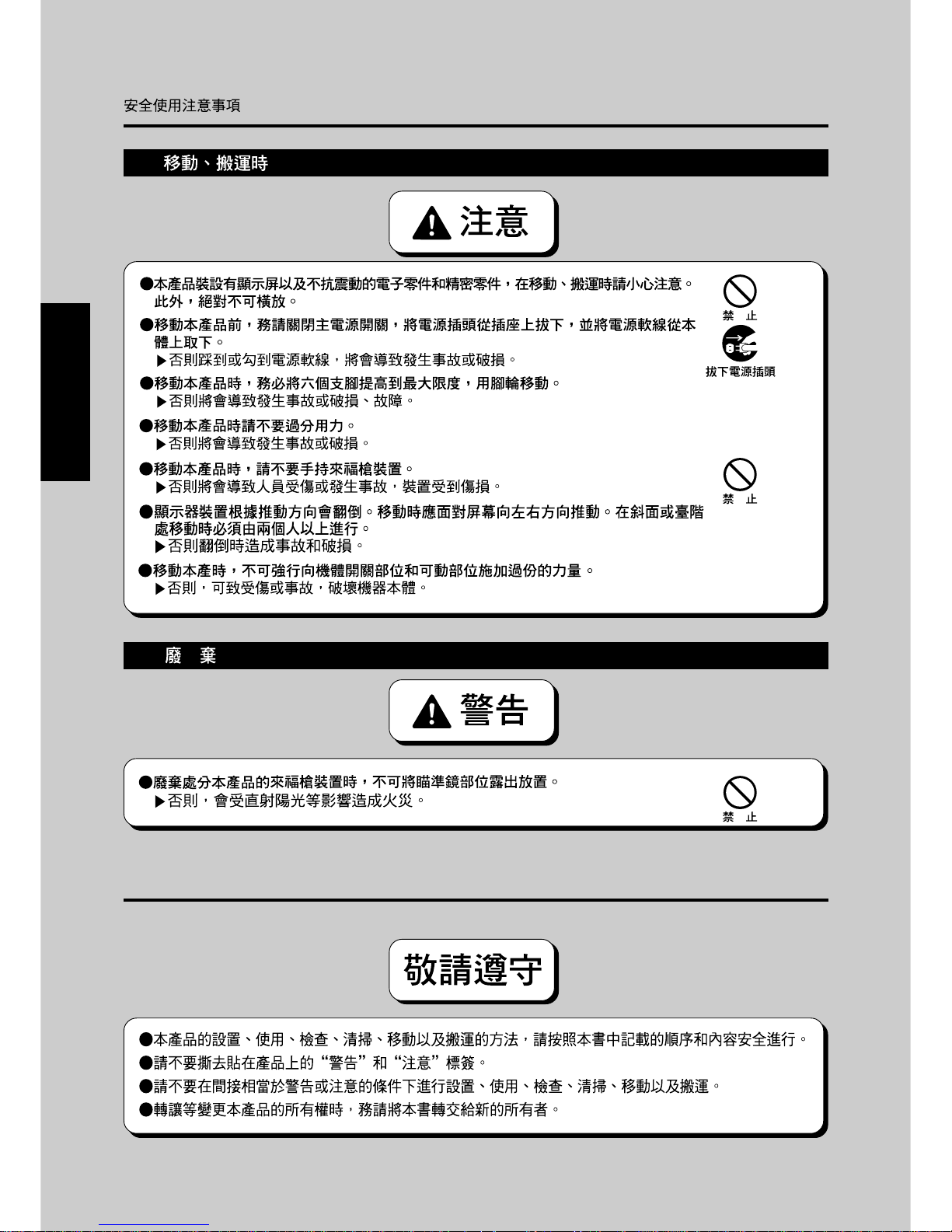
•When setting up, inspecting, maintaining, moving or transporting this product, follow the procedures and
instructions set forth in this manual and perform such work safely.
•Do not remove labels of “WARNING”, “CAUTION”, etc. attached to the product.
•Do not set up, handle, inspect, maintain, move or transport this product under conditions equivalent
to the condition of “WARNING” or “CAUTION” specified in this manual.
•If a new owner is to have this product as a result of transfer, etc., be sure to give this manual to the
new owner.
6
Precautions for use
ENGLISH
Moving and transportation
CAUTION
• The game machine contains parts such as the monitor, electronic components and
precision components which are sensitive to vibrations and impacts. Great care
therefore should be taken when moving and transporting the game machine.
Be sure not to let the machine tip over.
•Before moving the machine, be sure to turn OFF the main power switch, unplug the
power cord from the receptacle and remove the power cord from the machine.
·Stepping on or tripping over the power cord may result in an accident or damage the machine.
•Before moving the machine, be sure to fully lift the six adjusters and move it on the
casters.
·Otherwise, an accident, breakage or trouble may result.
•Do not apply a strong force for moving the machine.
·Otherwise, it may result in an accident or breakage of the units.
•Do not hold the rifle unit when moving the machine.
·Otherwise, it may result in an injury or damage to this product.
•When moving the monitor unit, be sure to push it along sideways (to the right or left).
When moving it on a slope or getting it over a level difference, be sure to take the
buddy system.
·Otherwise, the unit may turn over, resulting in an accident or damage.
•When moving the machine, take care that no undue force is applied to the
opening / closing sections or moving sections of the machine.
·Otherwise injury, accidents or machine damage may result.
PRECAUTION
IN HANDLING
Disposal
WARNING
•When disposhing of the rifle unit of this product, do not leave it with the scope exposed.
·Doing so could result in fire due to direct sunlight, etc..
Page 9
7
1
2
3
4
5
6
7
8
9
10
11
12
13
1
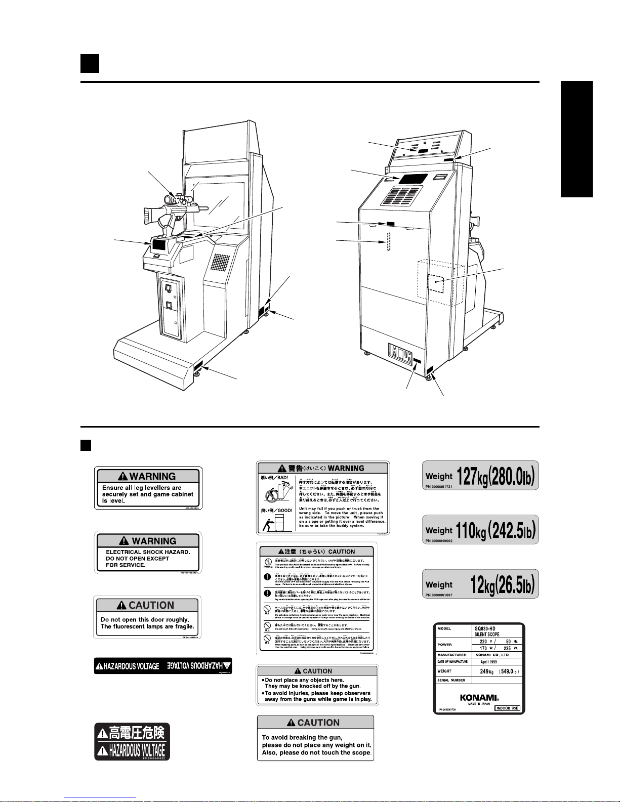
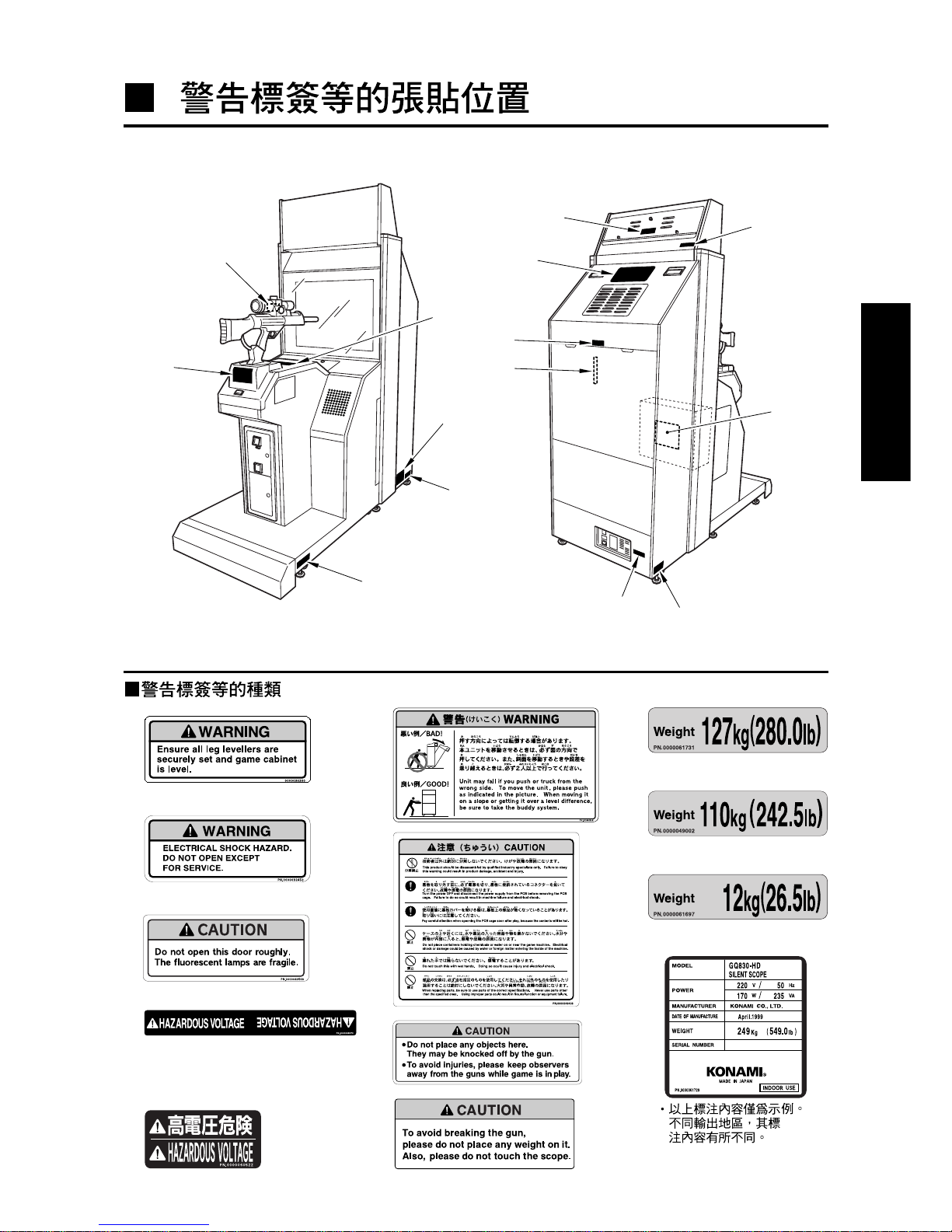
Locations of warning and other safety labels
ENGLISH
Types of warning and other safety labels
1
2
3
6
7
8
4
5
9
10
11
12
13
• The above is an example.
The entries are different
from destination to
destination.
Page 10
8
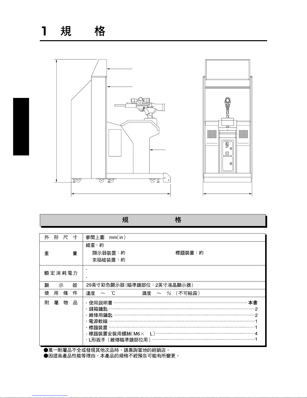
Refer to the figure above : mm (in)
Approx.249 kg (549 lb)
1 Monitor unit: Approx. 127 kg (280.0 lb) 3
T itle unit : Approx. 12 kg (26.5 lb)
2 Control unit : Approx. 110 kg (242.5lb)
•GQ830-TB : 215W (MAX)
•GQ830-HD: 170W (235VA)
29-inch CRT(Scope: 2-inch LCD)
Temperature 10 to 35˚C (50 to 95˚F), Humidity 20 to 80% (No dewing is allowed.)
·Instruction manual ……………………………………… This manual
·Keys for coin door ……………………………………………………… 2
·Keys for maintenance ………………………………………………… 2
·AC power cord ………………………………………………………… 1
·Title unit ………………………………………………………………… 1
·Title unit mounting screw (M6 x 15L)………………………………… 4
·Allen wrench (for servicing the scope) ……………………………… 1
•If any part is defective or not found, contact your nearest dealer.
•The specifications of this product are subject to change without notice for reasons such as
improving the performance.
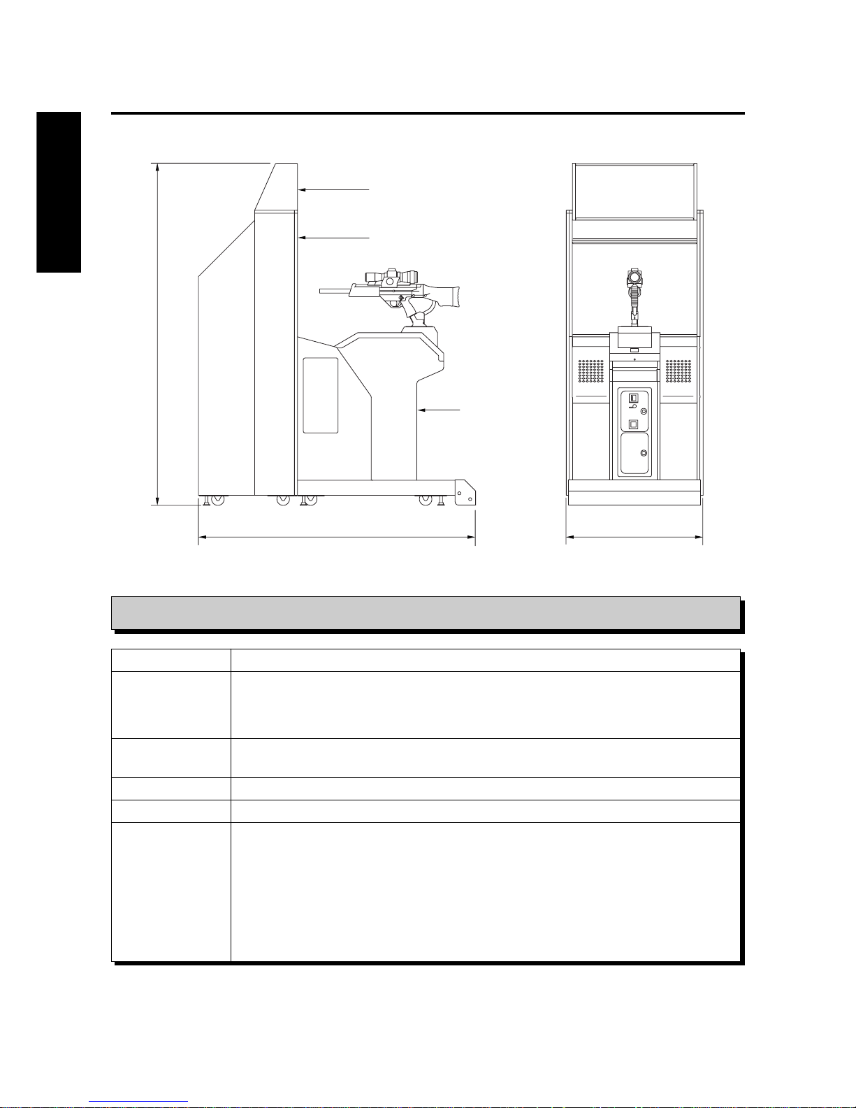
1 Specifications
Specifications
Dimensions
Weight
Rated power consumption
Monitor
Service condition
Attachments
ENGLISH
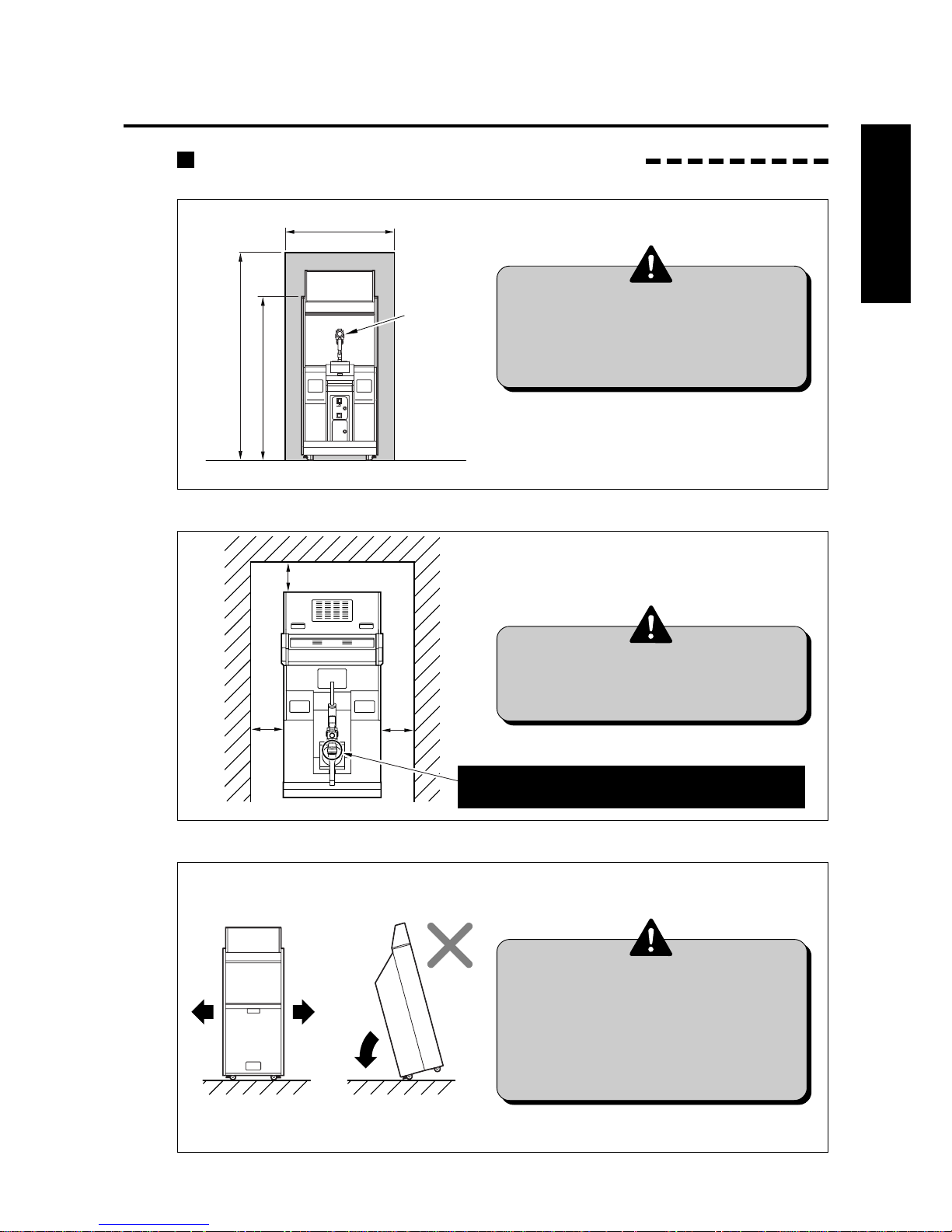
2040 (80.3)
1653 (65.1) 816 (32.1)
1
2
3
Page 11
9
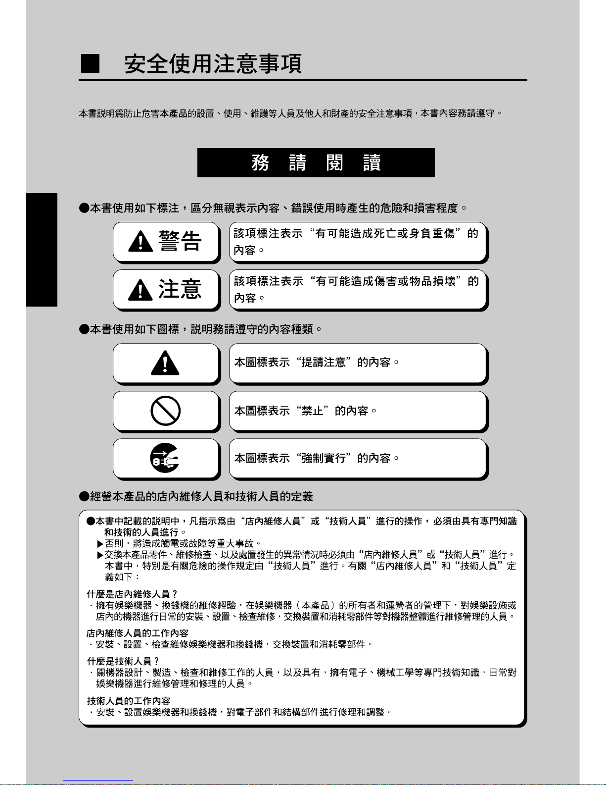
100 mm(3.94 in) or more
(space for heat rediation)
100 mm(3.94 in)
or more
100 mm(3.94 in)
or more
Place the rifle unit to keep its scope away
from direct sunlight or other strong light.
ENGLISH
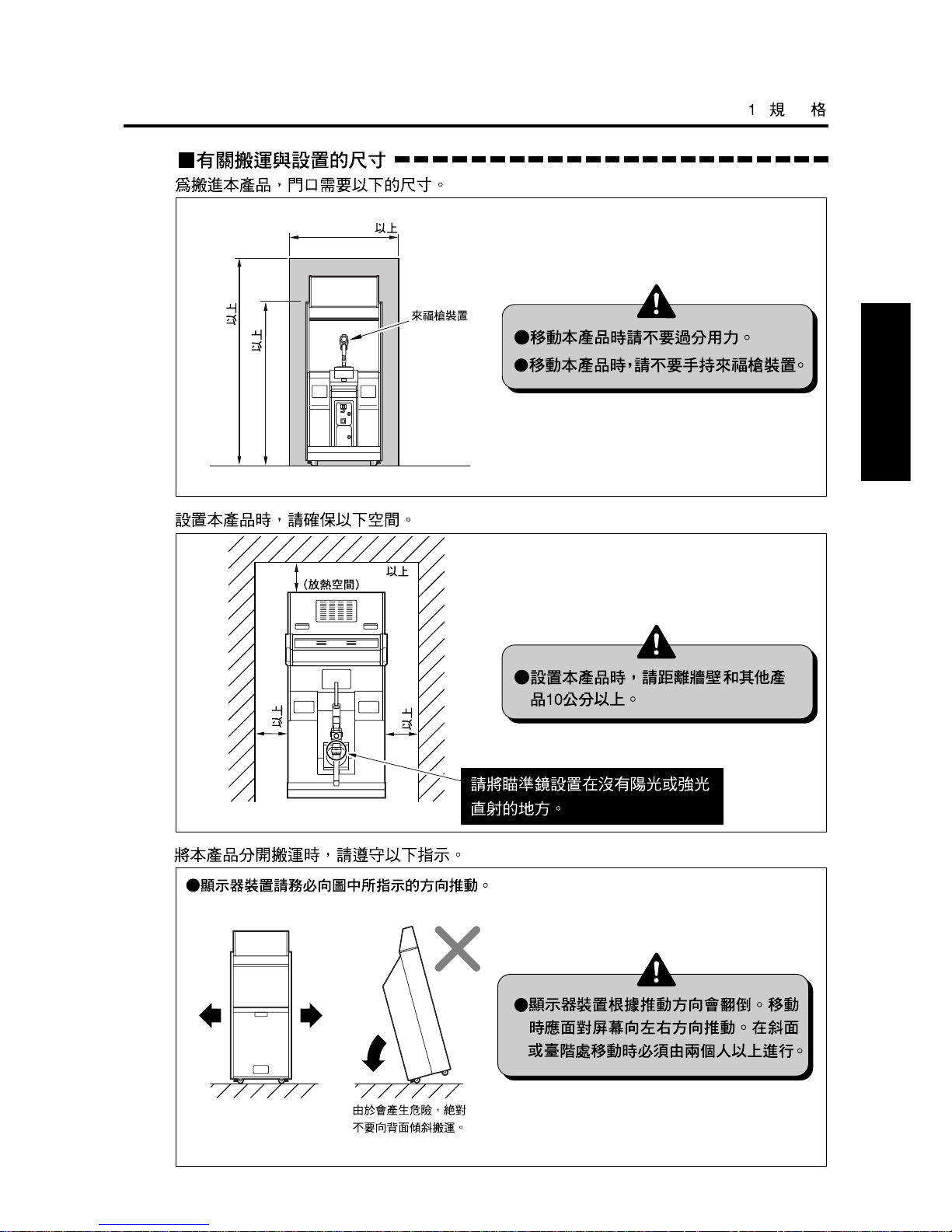
Allowance for Carrying-in and Installation of Product
The following allowance dimensions are necessary for carrying the product indoors.
Provide a space of the following dimensions for installation of the product.
•Install the product more than 100
mm(3.94 in) away from the wall
and other products.
•Do not apply a strong force for
moving the machine.
•Do not hold the rifle unit when
moving the machine.
ENGLISH
Follow the instructions below when carrying in this product with its units disconnected.
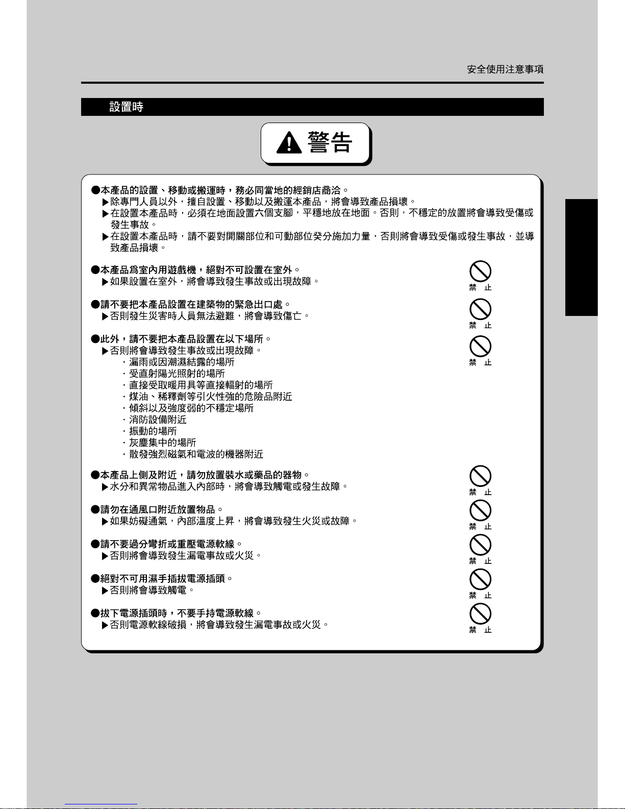
•When moving the monitor unit, be
sure to push it along sideways (to
the right or left). When moving it
on a slope or getting it over a level
difference, be sure to take the
buddy system.
•T o move the monitor unit, be sure to push
it in either of the directions of arrow.
2040 mm(80.3 in) or more
816 mm(32.1 in) or more
Rifle unit
1800 mm(70.9 in) or more
Never move the monitor
unit tilted backward.
It is hazardous.
1 Specifications
Page 12
10
CHINESE
10
Page 13
11
CHINESE
11
Page 14
12
CHINESE
12
Page 15
13
CHINESE
13
Page 16
14
CHINESE
14
Page 17
15
CHINESE
1
2
3
6
7
8
1
2
3
4
5
6
7
8
9
10
11
12
13
1
4
5
9
10
11
12
13
Page 18
16
CHINESE
127kg (280.0lb)
249kg (549lb)
12kg (26.5lb)
110kg (242.5lb)
GQ830-TB : 215W (MAX)
GQ830-HD : 170W (235VA)
(50~95˚F)3510 20 70
13
2
15
2040 (80.3)
1653 (65.1)
816 (32.1)
1
2
3
Page 19
17
100 mm(3.94 in)
100 mm(3.94 in)
100 mm(3.94 in)
CHINESE
816 mm(32.1 in)
1800 mm(70.9 in)
2040 mm(80.3 in)
Page 20
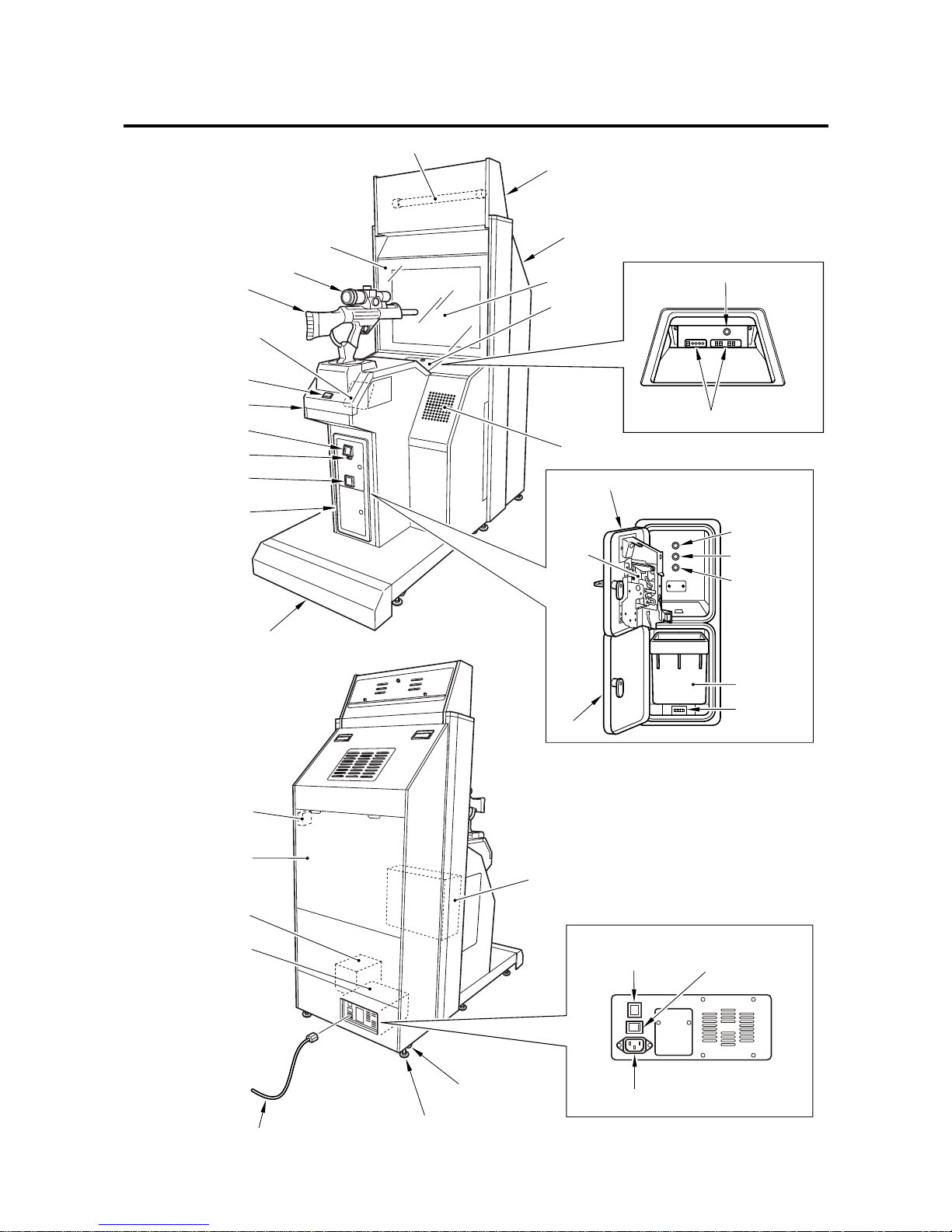
18
2 Names of parts
Fluorescent light
Monitor glass
Rifle unit
Speaker
Start button
Coin input port
Control unit
Title unit
Monitor unit
Main
monitor
Speaker
Coin return lever
Coin return port
Coin door unit
Step cover
Door switch
Back door
Power unit
Transformer
AC power cord
Adjuster
Caster
PCB unit
Coin door
Power unit
Maintenace door
Coin
selector
Monitor adjustment PCB
Demagnetizing button (Main monitor)
Main power switch
Circuit protector
Power inlet
Test button
Service button
Demagnetizing
button
(Main monitor)
Coin box
Coin counter
Scope
Monitor
adjustment
door
Page 21

19
3 How to play
How to play
1
Put coin(s) into the coin input port and press the start button.
2 The play mode select screen shows up. In less than 15 seconds, move the rifle unit to
select a mode and pull the trigger to enter the mode. (To enter the mode, you can press the
start button instead.)
·Shooting range mode ...... The player tries to get the highest score possible within a
specified time in the firing range.
·Story mode ...................... A story progresses in which you come to the rescue of the
president from a terrorist group.
·Time attack mode ............ On some stages of the story mode, you are challenged to clear
all the targets in the shortest time possible.
Play modes includes the three courses: beginners, intermediate
and advanced.
3 Once a play mode has been selected, the game gets started automatically.
·Watch for an enemy on the main monitor screen, and looking through the scope, shoot at
it. The rifle is loaded with 5 bullets and can also be automatically reloaded no matter how
many times.
In the story mode, there are two ways to go from each stage. The story mode will be over
in one of the 2 ending styles.
·If you hit anyone but the enemies, you get a penalty and lose one of your life points.
·When you find a beauty (appearing in a swimsuit, bath towel or dress) through the scope,
you gain one life point.
4 The game is over when you have been attacked and lost all your life points or when the
game time is up.
The “SILENT SCOPETM” gun shooting game is for you to look into the rifle unit’s scope and
snipe at enemy characters. Looking through the scope, you can find images in the distance
or in the dark which cannot be pinpointed on the main monitor screen. You are challenged to
find out a target quickly and shoot at it precisely at the first fire.
Setting the hit effect at gunning down of an enemy
·There are some levels of a hit enemy’s bloodshed (hit effect) and sexual expression (sexual
content) to choose from. To make selections, refer to “GAME OPTIONS” screen on page
29.
Continuing the game
·You can continue the game if you take the procedure within about 20 seconds before the
game is over.
Page 22
20
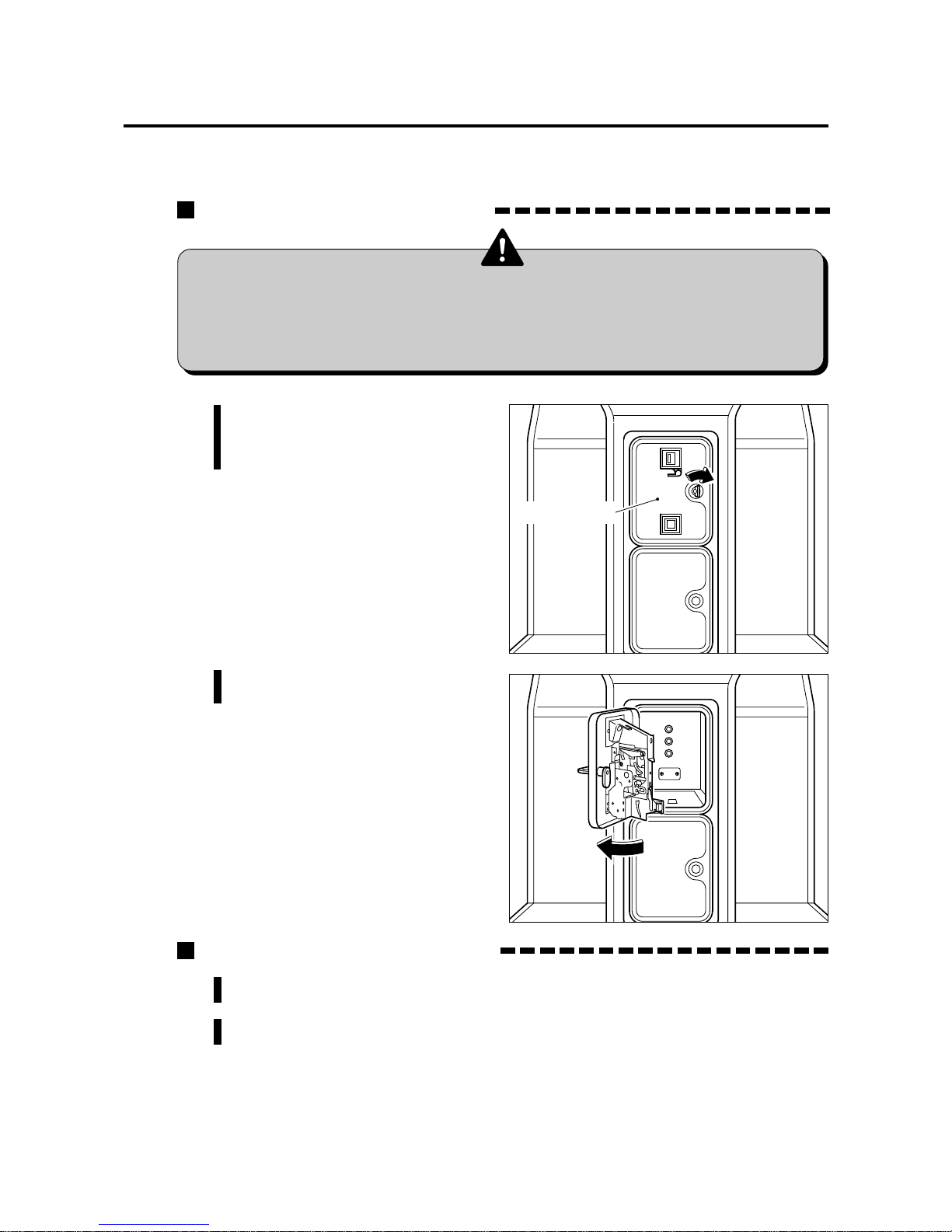
4 Opening and closing the doors
4-1 Opening and closing the maintenance door
How to open the maintenance door
1 Insert the accompanying
maintenance key and turn it
clockwise.
How to close the maintenance door
•Take care not to apply any load or impact to the maintenance door when
it is open.
•After closing the maintenance door , be sure to check that the door is locked
securely .
2 Open the maintenance door.
1 Close the maintenance door.
2 Turn the maintenance key counterclockwise and draw it out.
Maintenance door
Page 23
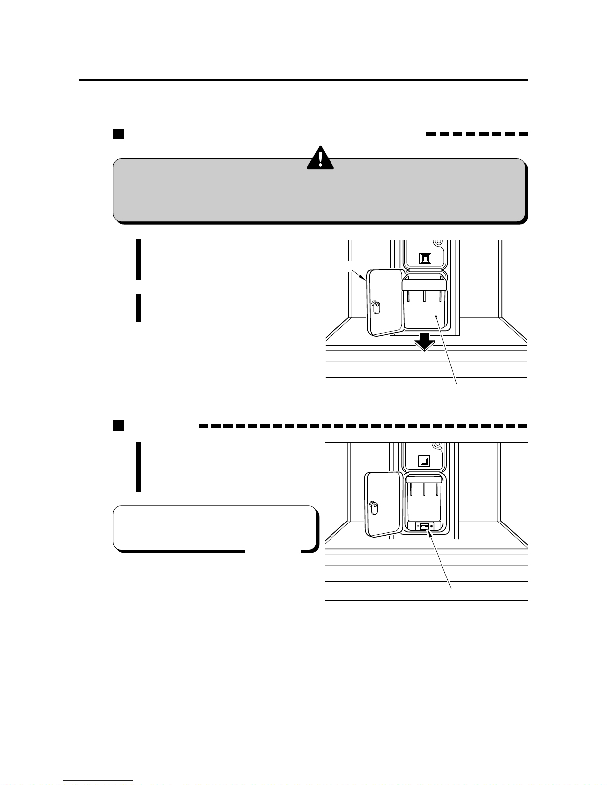
21
4 Opening and closing the doors
4-2 Opening and closing the coin door
Opening and closing the coin door and removing the coin box
1 Insert the attached coin door key
in the coin door and turn it
clockwise.
2 Open the coin door and take out
the coin box.
Coin counter
You will find the coin box when the
coin door is opened.
The coin counter is located under
the coin box.
•T ake care not to apply any load or impact to the coin door when it is open.
•Securely lock the door for protection against burglaries.
•Note that the coin box is considerably heavy to take out if it is full of coins.
•To move the coin counter onto the
service panel, see page 41.
MEMO
Coin door
Coin box
Coin counter
Page 24

22
Monitor
Monitor adjustment door Monitor
4 Opening and closing the doors
4-3
Opening and closing the monitor adjustment door
How to open the monitor adjustment door
1 Insert the accompanying
maintenance key and turn it
clockwise.
•When opening the monitor adjustment door, be careful not to hit it against
the monitor glass.
•When closing the monitor adjustment door , be very careful not to get your
finger pinched by the door.
1 Close the monitor adjustment door.
2 Turn the maintenance key counterclockwise and draw it out.
2 Open and detach the monitor
adjustment door .
How to close the monitor adjustment door
Page 25

23
5-1 Checking the game performance
5 Game settings
When the main power switch is turned ON after installation of machine, the game
Printed Circuit Boards (PCB) is checked automatically and the result is displayed
on the screen.
•Be sure to check the PCB unit (self test) before using the machine.
•Once the main power switch has been turned on (while the PCB unit is
being checked), never touch the rifle unit until the demonstration game
gets started.
•Preferably turn OFF the main power switch while the LCD screen of the
scope is off (this happens if the game is not played for longer than 30
seconds) in order to prolong the product service life.
•Do not change the DIP switch setting of this product to other than factory
setting.
•If an abnormality persists or the machine does not operate properly,
immediately turn OFF the main power switch, unplug the power cord from
the receptacle and contact your nearest dealer.
·The machine goes to the game mode and the demonstration game gets started.
If any abnormality is detected
· “BAD” appears on the screen, and the checking is repeated.
After the installation of this product or when the PCB unit has been repaired or
replaced, turn ON the power switch while pressing the test button of the service
panel to initialize the setting once to the original factory setting.
At this time, keep pressing the test button until “BACKUP DATA INITIALECOMPLETE/OPTION SETTINGS/RANKING DATA/BOOKKEEPING INCOME
DATA/PLEASE RELEASE TEST SWITCH” appears.
Never turn ON the power switch while holding down the test button.
All the “BOOKKEEPING” data will be erased. (The data once erased can
not be resumed.)
If an abnormal display continues or the machine does not operate normally,
immediately turn OFF the main power switch, unplug the power cord from the
receptacle and contact your nearest dealer.
Result of test
If test is OK
On-screen message at power on
When the machine is powered on for the first time after installation, the following
screen shows up. Set the clock on the “ BOOKKEEPING” screen. (See page 31.)
If the clock has not been set, this message appears each time the power is turned on.
When the clock has been set, the message does not appear at power on. It appears
again if the “BOOKKEEPING” data is cleared.
[CLOCK]
PRESS TEST SWITCH to MANUAL TEST MODE
Page 26

24
5 Game settings
5-2 Setting and adjustment of game mode
Manually check and change the settings for the screen displays and game contents
and change them as reguired.
Starting the test mode
1 Turn ON the main power switch.
2 While the demonstration game is playing, press the test button on the service
panel. (Do not turn ON the main power switch with the test button held down.
The current settings as well as the BOOKKEEPING data will be erased and the
machine will have the factory settings.)
·The main menu is displayed on the screen.
Quit the manual test mode
1 Pull the rifle unit’s trigger to select “GAME MODE” on the main menu screen.
2 Press the start button.
·The screen goes back to the game mode.
Main menu screen (basic items)
Selecting each mode
How to select each mode from the main menu.
·SELECT --> Pull the rifle unit’s trigger.
·SET --> Press the start button.
After selecting a mode, refer to the page on which that mode is described in details.
I/O CHECK
GUN CHECK
SCREEN CHECK
SCOPE SCREEN ADJUST
COLOR CHECK
MASK ROM CHECK
C.G. BOARD CHECK
SOUND OPTIONS
GAME OPTIONS
COIN OPTIONS
BOOKKEEPING
ALL FACTORY SETTINGS
GAME MODE
MAIN MENU
PULL GUN TRIGGER = SELECT ITEM
PRESS START BUTTON = EXECUTE
Displaying the products destination and version.
Checking the controls.
-->Page25
Checking the performance of the rifle unit.
-->Page26
Adjusting the monitor screen distortion.
-->Page26
Adjusting the scope screen position.
-->Page27
Adjusting the display color.
-->Page27
Checking the content of the MASK ROM in PCB unit.
-->Page27
Checking the C.G. board performance.
-->Page28
Setting various sound options.
-->Page28
Setting vatious game options.
-->Page29
Setting various coin options.
-->Page30
Displaying the bookkeeping information of coins.
-->Page31
Returning all the settings to factory ones.
-->Page33
Returning to game mode.
* * *
VER 1.00
•If an error happens in “SCOPE SCREEN ADJUST DATA” or “GUN VOLUME
DATA” at the start of the machine, a triangular marker is displayed at the error
item. Pick up the item and make new settings. The “GAME MODE” item does
not appear until those settings are properly made. This means the game cannot
be played.
MEMO
Page 27

25
5 Game settings
I/O CHECK
Checking the controls
The original factory settings are displayed in green; the changed settings are
displayed in red.
·Pull the rifle unit’s trigger to select a setting to be modified, and press the start
button to change the setting.
·After the setting has been changed, select “SAVE AND NEXT” and press the start
button for entry.
“NOW SAVING” will appear, the modified settings will be saved, and the screen
returns to the main menu.
·If “EXIT” is selected after the modification of the settings, the following message
will appear.
“YOU DID NOT SA VE. DO YOU W ANT T O SAVE? YES/NO” select “YES” or “NO”.
Pull the rifle unit’s trigger to select “YES” or “NO”. Press the start button for entry.
If “YES” is selected, the new settings will be saved with “NOW SAVING” displayed
and the screen will return to the main menu.
If “NO” is selected, the message “NO MODIFY SETTINGS” will appear , the modified
settings will not be saved, but the main menu will show up again on the screen.
•If “F ACTORY SETTINGS” is selected and the start button is pressed, all the settings
of the mode will go back to the factory ones.
•If “DEFAULT SETTINGS” is selected, the settings of the mode will become the
default ones.
MEMO
Mode for checking the performance of the controls.
To return to the main menu screen, pull the rifle unit’s trigger and press the start
button at once.
5-3 Mode descriptions
Displays ON/OFF according to the input.
ON ............. Switch turned ON.
OFF ........... Switch turned OFF.
Switches on and off the scope by holding down the service
and test buttons at once.
ON ............. Grid pattern on the scope screen.
OFF ........... Nothing on the scope screen.
Displays ON/OFF according to the input of the start button.
ON .............. Lights up.
OFF ............ Goes out.
Displays the hexadecimal value corresponding to the rifle
unit’s right-and-left motion.
·The “I” marking shifts to LEFT when the rifle points
leftward: to RIGHT when rightward.
Detects the backlash between the rifle unit’s right / left
control gears.
Displays the hexadecimal value corresponding to the rifle
unit’s up-and-down motion.
·The “I” marking shifts to BOTTOM when the rifle points
downward: to TOP when upward.
Detects the backlash between the rifle unit’s up / down
control gears.
GUN TRIGGER
OFF START BUTTOM
OFF
TEST SWITCH
OFF SERVICE SWITCH OFF
COIN1 MECH SWITCH OFF
SCOPE OFF START BUTTON LAMP OFF
GUN YAW LEFT RIGHT
Volume
Free
GUN PITCH BOTTOM TOP
Volume
Free
I/O CHECK
PRESS START BUTTON + GUN TRIGGER = EXIT
HOLD SERVICE SWITCH + PRESS TEST SWITCH = SCOPE ON/OFF
[0000]
+------+-------------+-------------+------+
[0000] +--------------------------+----------------+
[0000]
+------+-------------+-------------+------+
[0000] +--------------------------+----------------+
•This screen is just an example.
Page 28

26
GUN CHECK
Mode for adjusting and checking the rifle unit’s swing range.
Look at the screen for the marker that the gun barrel is pointing to. If the marker is
extremely out of position, press the test button on the service panel to call the gun
adjustment mode.
To return to the main menu screen or interrupt the gun adjustment mode, press the
start button.
Checking the performance of the rifle unit
SCREEN CHECK
Mode for checking the monitor screen display.
Adjust the focus, distortion and size of the image on the screen while watching the
crosshatch pattern. Use the monitor adjustment PCB (See page 56) to make
adjustments.
To return to the main menu screen, press the start button.
Adjusting the monitor screen distortion
PRESS TEST SWITCH = GUN ADJUST
PULL GUN TRIGGER = SHOOT
PRESS START BUTTON = EXIT
GUN CHECK
Marker
Make sure the marker is where the gun barrel is
pointing to.
Bullet mark
Pull the rifle unit’s trigger and make sure the bullet mark
is left.
Gun adjustment mode
This mode is intended to adjust the pinpointing of the rifle unit. Take the following
adjustment procedure.
1 Point the gun barrel to the lower-left corner of the screen, and pull the rifle unit’s
trigger.
2 Point the gun barrel to the upper-right corner of the screen, and pull the rifle unit’s
trigger.
3 The “NOW SAVING” message appears and the settings will be saved. Then the
“GUN CHECK” screen shows up again. Move the rifle unit and make sure the
marker is in position.
•This screen is just an example.
5 Game settings
Gun check mode
•If an error happens in “GUN VOLUME DA TA” at the start of the machine, the “Gun
adjustment mode” screen shows up itself.
•No image appears on the scope while in the “Gun check mode” and “Gun
adjustment mode”.
MEMO
Page 29

27
•The crosshatch pattern may appear slightly tilted on the scope screen. The
game is not affected, however.
MEMO
MASK ROM CHECK
Mode for checking the MASK ROM on the game PCB unit.
If the MASK ROM is not in trouble, “OK” is displayed: if in trouble, “BAD” is displayed.
Once in this mode, this checking gets started automatically. To return to the main
menu screen, press the start button.
•If “BAD” is indicated, turn OFF the power switch and turn it ON again. If “BAD” still
appears, write down the ROM number. And immediately turn OFF the main
power switch, unplug the power cord and contact your nearest dealer.
COLOR CHECK
Mode for checking the display color.
Make the adjustment using the monitor adjustment PCB (See page 56) so that the
colors of the color bars should appear properly graduated and the background should
become black sufficiently.
To return to the main menu screen, press the start button.
Adjusting the display color
Checking the content of the MASK ROM in PCB unit
SCOPE SCREEN ADJUST
Mode for adjusting the display position on the scope screen.
Pull the rifle unit’s trigger to select an item. Press the start button to modify the
setting.
Looking into the scope, adjust so that the crosshatch pattern be centered.
To return to the main menu screen, select “SAVE AND EXIT” or “EXIT” and press
the start button.
Adjusting the scope screen position
X:-5 Y: 5
UP
DOWN
LEFT
RIGHT
DEFAULT SETTINGS
SAVE AND EXIT
EXIT
Displays the displacement from the default settings.
Used to move up the scope screen by pressing the
start button.
Used to move down the scope screen by pressing the
start button.
Used to move the scope screen to the left by pressing
the start button.
Used to move the scope screen to the right by pressing
the start button.
Used to move back the scope screen to the default settings
by pressing the start button.
SCOPE SCREEN ADJUST
PULL GUN TRIGGER = SELECT OPTION
PRESS START BUTTON = EXECUTE
•This screen is just an example.
5 Game settings
Page 30

28
SOUND OPTIONS
Setting various sound options
Mode for setting and checking the sound options.
Pull the rifle unit’s trigger to select an item. Press the start button to modify the
setting.
To return to the main menu screen, select “SAVE AND EXIT” or “EXIT” and press
the start button.
C.G. BOARD CHECK
Mode for checking the C.G. board function.
Check the function of the C.G. board by watching the motion on the screen in this
mode to see if the board works normally or not.
To return to the main menu screen, press the start button.
Checking the C.G. board performance
PULL GUN TRIGGER = SELECT OPTION
PRESS START BUTTON = EXECUTE
SOUND IN ATTRACT MODE
ALL THE TIME
VOLUME SETTING 20
SCALE CHECK
POLICE CAR SIREN ON
BGM IN GAME MODE ON
FACTORY SETTINGS
SAVE AND EXIT
EXIT
SOUND OPTIONS
Turns on and off the demo play sound.
·ALL THE TIME......................Sound always on.
·ONCE EVERY 4 CYCLES...
Sound on every 4 cycles.
·COMPLETELY OFF.............Sound always off.
Adjusts the sound volume level of voice and sound effects
in the range of 0 (mute) to 30 (maximum).
*To raise the sound level, press the start button.
*To lower the sound level, press the start button so
many times that the zero level is reached and make a
new setting.
You will hear a do-re mi...do musical scale from
the left speaker first and then from the right
speaker, which is repeated twice.
(Sound effect is given for the 2nd round.)
Switches on and off the police car siren during the game.
·ON ......... Siren on as specified.
·OFF ....... Siren always off.
Sets to give background music while the game is being
played.
·ON ......... Background music heard.
·OFF ....... Background music not heard.
Press the start button to return all the settings to the
factory settings.
PRESS START BUTTON = EXIT
C. G. BOARD CHECK
The product’s logo mark flashes semi-transparent here.
(The KONAMI logo mark appears on the scope.)
Two cubes are turning entangled each other behind the
logo mark.
•This screen is just an example.
5 Game settings
Page 31

29
GAME OPTIONS
Mode for setting and checking the game options.
Pull the rifle unit’s trigger to select an item. Press the start button to modify the
setting.
To return to the main menu screen, select “SAVE AND EXIT” or “EXIT” and press
the start button.
Setting various game options
GAME OPTIONS
DIFFICULTY LEVEL 4 : MEDIUM
BRANCH SELECT ON
PLAYER`S LIFE 3
VIOLENT MODE STRONG
HIT EFFECT FLASH
SEXUAL CONTENT NORMAL
NIGHT MODE BRIGHT 10
SCOPE IN ATTRACT MODE
AUTO CONTROL
REAL TIME WINDOW OFF
RECORD SAVE
OFF
RECORD DATA CLEAR
FACTORY SETTINGS
SAVE AND EXIT
EXIT
PULL GUN TRIGGER = SELECT OPTION
PRESS START BUTTON = EXECUTE
Sets the difficulty level (from the 8 levels).
1:EASIEST ...............Easier
2:VERY EASY
3:EASY
4:MEDIUM ..............Standard
5:MEDIUM HARD
6:HARD
7:VERY HARD
8:HARDEST .............Harder
Sets whether the player can choose from the routes
(branches) during the game.
· ON ........For the player to select.
· OFF ......Automatically selected.
Sets the player’s life points from 1 to 8.
Sets the presence or absence of viorent expression when
an enemy is hit.
· STRONG .......Displays tht the enemy's head gets hit.
· MILD
..............
Does not display that the enemy's head
gets hit.
Sets the hit effect when an enemy is gunned down.
· FLASH .......Flashing.
· RED ...........Red blood spurts.
· BLUE .........Blue blood spurts.
· GREEN .....Green blood spurts.
· YELLOW ...Yellow blood spurts.
Sets the sexual content during the game.
· NORMAL ...Ordinary expression (ladies in bikini).
· MILD ..........Mild expression
(ladies in one-piece swimsuit)
.
Adjusts the dark-field stage brightness from 1 to 16.
A window appears on the right of the screen with ladies at
the left front, at the center, and at right in the background.
Adjust so that the lady at right in the background
disappears.
Decides on whether the scope-screen image is displayed
on the main screen during the demonstration game.
· COMPLETELY OFF ...Off all the time (scope-screen
image not displayed).
· AUTO CONTROL .......Scope-screen image turned on
when there is an input/output
during the demonstration game.
But automatically turned off if
there is no input/output for 30
seconds (effective to prolong the
LCD’s backlight life.)
Decides on whether the scope-screen image is displayed
on the main monitor screen during the game.
· ON ........Displayed.
· OFF ......Not displayed.
Records the ranking data.
· ON ........Data saved.
· OFF ......Data not saved.
Clears the ranking data.
Press the start button to return all the settings to the
factory settings.
•This screen is just an example.
5 Game settings
Page 32

30
5 Game settings
COIN OPTIONS
Mode for setting and checking the coin options.
Pull the rifle unit’s trigger to select an item. Press the start button to modify the
setting.
To return to the main menu screen, select “SAVE AND EXIT” or “EXIT” and press
the start button.
Setting various coin options
•The coin setting options are not displayed when “FREE PLA Y” is set to “ON”.
In such case, remember the games will be free.
FREE PLAY OFF
COIN MECHANISM COMMON
COIN SLOT 1 1COIN(S) 1CREDIT(S)
COIN SLOT 2 1COIN(S) 1CREDIT(S)
START 2CREDIT(S) to START
CONTINUE
1CREDIT(S) to CONTINUE
FACTORY SETTINGS
SAVE AND EXIT
EXIT
COIN OPTIONS
PULL GUN TRIGGER = SELECT OPTION
PRESS START BUTTON = EXECUTE
Selects a free play.
ON............Available for free play.
OFF..........Not available for free play.
Always keep it set to COMMON.
Sets the number of credits for the coin.
(Presettable to 16 coins for 1 credit through 1 coin for 16
credits)
Sets the number of credits required to start the game.
(Presettable to 1 thru 16 credits)
Sets the number of credits required to continue the game.
(Presettable to 1 thru 16 credits)
Press the start button to return all the settings to the
factory settings.
•This screen is just an example.
Page 33

31
Total number of
coins for last
7 days
Total number of
coins for past 52
week
Indication of
play conditions
Total number of
coins by hours and
days of the week
PULL GUN TRIGGER = SELECT OPTION
PRESS START BUTTON = EXECUTE
BOOKKEEPING
CLOCK SETUP
G.M.T
SET TO HOUR : 16 07
MINUTE
: 27 27
SECOND
: 42 42
SAVE AND EXIT
EXIT
Displays the Greenwich Mean Time.
Sets the current hour.
Sets the current minute.
Sets the current second.
5 Game settings
BOOKKEEPING
Mode for displaying the total data on the number of coins put in the machine.
If the time is preset on the “CLOCK SETUP” screen, the total data on the number of
coins put into the machine can be checked for each coin slot.
Pull the rifle unit’s trigger to select “HOUR”, “MINUTE”, and “SECOND”. Press the
start button to adjust the current time.
Make sure the current time is correct, select “SAVE AND EXIT” and press the start
button. (The current time is now set and the main menu screen shows up.)
Displaying the bookkeeping information of coins
•If the time setting has not been made — for example, after the machine has been
set up or initialized —, the “CLOCK SETUP” screen shows up.
•When the time setting has been modified, the bookkeeping information is
automatically cleared. With the current time not set, the total of received coins
and other bookkeeping data are not displayed. (The data once erased can not
be resumed.)
MEMO
When the time has been preset on the “CLOCK SETUP” screen as shown above,
the following “BOOKKEEPING” information is displayed on the screen. Select
“NEXT DATA SUMMARY” and press the start button, and the screen will switch in
the following sequence. To return to the main menu screen, select “EXIT” and
press the start button.
Also, when the current time has been set and “INCOME DATA CLEAR” has been
selected and the start button pressed, the current time and BOOKKEEPING data
can be cleared.
At this time, the question “DO YOU WANT T O CLEAR DAT A? YES/NO” is indicated
on the screen. Pull the rifle unit’s trigger to select “YES” or “NO”. If “YES” is
selected, “NOW CLEARING” appears on the screen and the “BOOKKEEPING” data
will be deleted. The data will be saved in the factory settings and the main menu
screen will show itself up.
If “NO” is selected, “NO MODIFIED” is indicated and the main menu appears again
without deletion of the data.
•This screen is just an example.
Page 34

32
PULL GUN TRIGGER = SELECT OPTION
PRESS START BUTTON = EXECUTE
BOOKKEEPING
Total number of coins after the time being set.
Average number of coins of last 7 days.
Number of coins of today.
Number of coins of yesterday.
Number of coins of 2 days ago.
Number of coins of 3 days ago.
:
:
Number of coins of 7 days ago.
Goes to the next data.
Clears the current time and the income data.
INCOME DATA of LAST 7DAYS
SLOT1 SLOT2
TOTAL
LAST 7DAYS AVERAGE
TODAY
YESTERDAY
-2DAY
-3DAY
:
:
-7DAY
NEXT DATA SUMMARY
INCOME DATA CLEAR
EXIT
0 0
0 0
0 0
0 0
0 0
0 0
0 0
PULL GUN TRIGGER = SELECT OPTION
PRESS START BUTTON = EXECUTE
BOOKKEEPING
Number of coins by hours and days of the week.
Total number of coins by days of the week.
Goes to the next data.
Clears the current time and the income data.
COIN SLOT1 INCOME DATA of WEEK
TIME SUN MON TUE WED THU FRI SAT TOTAL
0:00 0 0 0 0 0 0 0 0
2:00 0 0 0 0 0 0 0 0
4:00 0 0 0 0 0 0 0 0
:
:
:
22:00 0 0 0 0 0 0 0 0
TOTAL 0 0 0 0 0 0 0 0
NEXT DATA SUMMARY
INCOME DATA CLEAR
EXIT
5 Game settings
Screen of the total number of coins for last 7 days
Screen of indication of play conditions
Screen of the total number of coins for past 52 weeks
Screen of the total number of coins by hours and days of the week
•This screen is just an example.
•This screen is just an example.
•This screen is just an example.
•This screen is just an example.
PULL GUN TRIGGER = SELECT OPTION
PRESS START BUTTON = EXECUTE
BOOKKEEPING
Displays the total active time since the time setting.
Displays the total play time.
Displays the activity rate
(total play time total active time)
.
Displays the average play time.
Displays the number of plays (continuities not included).
Displays the number of continuities.
Displays the total number of plays.
Displays the number of story mode plays
(continuities not
included).
Displays the number of shooting range mode plays.
Displays the number of beginning-level time attack mode
plays.
Displays the number of intermediate-level time attack
mode plays.
Displays the number of advanced-level time attack mode
plays.
PLAY DATA SUMMARY
TOTAL ACTIVE TIME 0h 0m 0s
TOTAL PLAY TIME 0h 0m 0s
ACTIVITY RATE
0%
AVWRAGE PLAY TIME
0m 0s
ONE TIME ONLY COUNT
0
CONTINUE COUNT
0
SOLD PLAY COUNT
0
STORY MODE
0
SHOOTING RANGE
0
T.A.EASY
0
T.A.MEDIUM
0
T.A.HARD
0
NEXT DATA SUMMARY
INCOME DATA CLEAR
EXIT
PULL GUN TRIGGER = SELECT OPTION
PRESS START BUTTON = EXECUTE
BOOKKEEPING
Number of coins of 1 week before.
Number of coins of 2 week before.
:
:
:
:
Number of coins of 52 weeks before.
Goes to the next data.
Clears the current time and the income data.
COIN SLOT1 INCOME DATA of LAST 52 WEEKS
-01:00000 -02:00000 -03:00000 -04:00000
-05:00000 -06:00000 -07:00000 -08:00000
-09:00000 -10:00000 -11:00000 -12:00000
:
:
:
:
-49:00000 -50:00000 -51:00000 -52:00000
NEXT DATA SUMMARY
INCOME DATA CLEAR
EXIT
Page 35

33
5 Game settings
ALL FACTORY SETTINGS
Mode for returning the test-mode settings to the factory settings.
Pull the rifle unit’s trigger to select “YES” or “NO” and press the start button for entry.
If “YES” is selected, the question for re-confirmation appears on the screen.
If “YES” is selected again, the “NOW SA VING” message appears on the screen and
the next test-mode settings are saved as the factory settings.
• SOUND OPTIONS
• GAME OPTIONS
• COIN OPTIONS
If “NO” is selected, “NO MODIFY SETTING” is indicated. This means the modified
settings are not saved.
Returning all the settings to factory ones
Page 36

34
6 Installation and assembling
How to fasten the adjusters
•Adjust the adjusters so that the casters do not touch the floor.
Take care not to exceed the maximum adjusting height of the adjuster.
•Make all the 6 adjusters come in contact with the floor, tighten them with
hexagon nuts after making sure that all the units are placed stably in a
horizontal position.
6-1 Fastening the adjusters
Lift the caster about 5 mm
(0.2 in) from the floor.
Hexagon nut
Max.adjustable height:
70 mm (2.76 in)
Min. 65 mm (2.56 in)
Page 37

35
How to install the step cover
6-2 Installing the step cover
First make sure the machine is secured with the adjusters and then attach the step
cover as shown below.
1 Remove the screws and detach the
step cover.
2 Place the step cover back in
position and fix it with the above four
screws. See the figure at right.
Step cover
Screws
6 Installation and assembling
Screws
Page 38

36
How to install the title unit
6-3 Installing the title unit
1 Be sure to turn OFF the main power
switch and unplug the power cord
from the receptacle.
2 Connect all the specified
connectors. Place the title unit on
the monitor unit with care not to get
the wires caught between them.
3 Fix the title unit with the
accompanying title unit mounting
screws.
Connectors
Title unit
Title unit
mounting
screws
(M6x15L)
•Before installing the title unit, be sure to turn OFF the main power switch
and unplug the power cord from the receptacle.
•Before installing the title unit, make sure the adjusters of the machine are
tight on the floor.
•The title unit weights approx. 12kg(26.5lb). Be sure to make a team of 2
people or more and to use stepladders or the like for added safety.
•When connecting the title unit, take care not to catch the wiring and your
hand between the unit.
•When placing the title unit on the monitor unit, be careful not to get your
hand and the wires caught between them.
•Fix each of the unit on the monitor unit and fix it by tighting the screws.
MEMO
Service panel
6-4 Service panel
Using the accompaying maintenance key, open and detach the maintenance door
to access the service panel inside.
Service panel
Test button
Service button
Coin counter
compartment
Demagnetizing
button
(Main monitor)
6 Installation and assembling
Page 39

37
Power unit
6-5 Power unit
The power supply unit is provided at the rear side of the machine.
•Be sure to use the attached AC power cord.
•Be sure to ground to the machine. Never connect the grounding wire to
gas pipe, water pipe or telephone ground terminal.
•There are high-voltaged parts inside the product. Other persons than
qualified industry specialist should not open the back door and side door .
When the back door and side door is opened, pay due attention not to
touch the inside unnecessarily.
•When opening the back door and side door , be sure to turn OFF the main
power switch and unplug the power cord from the receptacle.
•Preferably turn OFF the main power switch while the LCD screen of the
scope is off (this happens if the game is not played for longer than 30
seconds) in order to prolong the product service life.
6 Installation and assembling
Power unit
Circut protector
Main power switch
Power inlet
Door switch
Back door
AC power cord
Side door
Page 40

38
6-6 Separating the machine
How to separate the machine
The machine can be divided into the units.
•Before separating the units from the machine, be sure to turn OFF the
main power switch and remove the power cord plug from the receptacle.
•Before moving the machine, be sure to turn OFF the main power switch,
unplug the power cord from the receptacle and remove the power cord
from the machine.
•Before moving the machine, be sure to fully lift the six adjusters and move
it on the casters.
•When moving the monitor unit, be sure to push it along sideways (to the
right or left). When moving it on a slope or getting it over a level difference,
be sure to take the buddy system.
•When connecting the separated units, take care not to catch the wiring
and your hand between the units.
1 Be sure to turn OFF the main power
switch and unplug the power cord
from the receptacle.
2 Raise the six adjusters to let the
casters come in contact with the
floor.
How to separate the monitor unit and control unit
3 Unscrew the fixtures off both sides.
Draw the units 100 mm (3.94 in) or
shorter apart from each other.
•Be careful not force the units too far
from each other. The wires connected
between the units may be damaged
inside.
•Fix each of the unit on the monitor unit
and fix it by tighting the screws
MEMO
100 mm
(3.94 in) or shorter
Monitor unit
Fixture
Screws
Control unit
6 Installation and assembling
Raise the adjusters and bring down the casters
on the floor.
Hexagon nut
Page 41

39
4 Disconnect all the connectors.
Monitor unit
Control unit
Connectors
6 Installation and assembling
Page 42

40
Separating the title unit
•Before separating the title unit, be sure to turn OFF the main power switch
and unplug the power cord from the receptacle.
•Before detaching the title unit, make sure the adjusters of the machine are
tight on the floor.
•The title unit weighs approx. 12 kg (26.5 lb). Be sure to make a team of 2
people or more and to use stepladders or the like for added safety.
•When reconnecting the title unit, take care not to catch the wiring and
your hand between the units.
1 Be sure to turn OFF the main power
switch and unplug the power cord
from the receptacle.
2 Remove the lock screws off the
title unit. Lift the title unit slightly
and disconnect the connectors.
MEMO
•Be careful not to force the title unit up
too far. The wires connected may be
damaged inside.
Connectors
Title unit
Title unit
mounting
screws
(M6x15L)
6 Installation and assembling
Page 43

41
6-7 Moving the coin counter
How to move the coin counter
The coin counter was installed in the coin box when the machine left the factory,
but it can be moved onto the service panel.
•Before moving the coin counter , be sure to turn OFF the main power switch
and unplug the power cord from the receptacle.
1 Be sure to turn OFF the main power
switch and unplug the power cord
from the receptacle.
2 Open the coin door and take out the
coin box. Remove the screws and
take out the coin counter.
In the meanwhile, disconnect the
connectors.
3 Remove the maintenance door and
unscrew the blind cover to remove
it from the service panel.
6 Installation and assembling
Connectors
Coin counter
Screws
Blind cover
Screws
Connectors
Coin counter
Screws
Blind cover
Screws
4 Draw the connector out of the opening
of the service panel and connect
this connector to the coin counter’s
connector.
5 Attach the coin counter on the
service panel with the screws.
6 Attach the blind cover (detached in
Step 3 above) back in position on
the coin counter using the screws.
7 Place the coin box back into
position and close the coin door.
Page 44

42
7-1 Replacing the coin selector
How to replace the coin selector
•Before replacing the coin selector, be sure to turn OFF the main power
switch and unplug the power cord from the receptacle.
•When replacing parts, be sure to use parts of the correct specifications.
Never use parts other than the specified ones.
•Strictly refrain from disassembly and repair of parts which are not indicated
in this manual, as well as settings and remodelling.
1 Be sure to turn OFF the main power
switch and unplug the power cord
from the receptacle.
2 Open the maintenance door.
3 Release the levers that fix the coin
selector. See at right.
7 Maintenance
5
To fit the coin selector again
Fit the 2 projections of the coin
selector to their mating notches.
6 Lock the levers (in Step 3 above)
again, and close the maintenance
door.
4 Slide the coin selector to the right,
and take it out.
Maintenance door
Lever
Microswitch
Coin selector
Slide in this
direction.
Projections
Notch
Page 45

43
7 Maintenance
7-2 Replacing the fluorescent light
How to replace the fluorescent light
•Before replacing the fluorescent light, be sure to turn OFF the main power
switch and unplug the power cord from the receptacle.
•Gently open the fluorescent light cover .
•The florescent light is hot just after the power switch is turned off.
Wait until it cools down and then replace it with a new one of the same
type (straight tube 20W / 100V).
•When replacing parts, be sure to use parts of the correct specifications.
Never use parts other than the specified ones.
•Strictly refrain from disassembly and repair of parts which are not indicated
in this manual, as well as settings and remodelling.
1 Be sure to turn OFF the main power
switch and unplug the power cord
from the receptacle.
2 Remove the screws off the back
cover (see at right). Hold the knob
and gently open the cover.
3 Push one end of the fluorescent
light in the direction of the socket.
The other end of the fluorescent
light will be detached from the
opposite socket.
4 Install a new fluorescent light in the
reverse order.
•It is recommended to replace the glow lamp at the same time.
MEMO
Screws
Cover
Knob
Fluorescent light
(straight tube 20W/100V)
Glow lamp (FG-1E)
Push in this direction
Page 46

44
7 Maintenance
How to replace the start button
•Before replacing the start button, be sure to turn OFF the main power
switch and unplug the power cord from the receptacle.
•When replacing parts, be sure to use parts of the correct specifications.
Never use parts other than the specified ones.
•Strictly refrain from disassembly and repair of parts which are not indicated
in this manual, as well as settings and remodelling.
7-3 Replacing the start button
1 Be sure to turn OFF the main power
switch and unplug the power cord
from the receptacle.
2 Remove the screws and datach the
cover .
3 Disconnect the connectors.
MEMO
•Be careful not to force the cover up
too far. The wires connected may be
damaged inside.
4 Remove the screw off the band that
secures the button and the socket.
5 Pull out the socket from the button.
Screws
Cover
Connectors
Socket
Screw
Band
Page 47

45
7 Maintenance
•Replacing the socket
Reconnect the wires to a new socket as shown below.
MEMO
6 Loosen the nut and separate the
button.
7
To fit the button again
To install the button, take the
reverse procedure.
8 Pay attention to the posture of
socket and assemble it in the
reverse of disassembly , using care
not to confuse the wires.
10 Mount the cover into position.
9 Reconnect the connectors
(disconnected in Step 3 above).
11 Take the steps in “5-1 Checking the game performance (self test)” on page 23
and the steps in “I/O CHECK” on page 25.
Button
Guide
Nut
Be careful not to hit against
the socket.
Wires for button lamp
Orange(+)
Black
Green( )
Purple
COM
NO
Wires for microswitch
LED
Be sure to connect the orange
and green wires to the (+) and
( ) terminals, respectively, that
are marked on the LED PC board.
Page 48

46
•Before replacing the rifle unit, be sure to turn OFF the main power switch
and unplug the power cord from the receptacle.
•The rifle unit weighs approx. 4 kg (8.8 lb). Be careful not to drop it.
•When replacing parts, be sure to use parts of the correct specifications.
Never use parts other than the specified ones.
•Strictly refrain from disassembly and repair of parts which are not indicated
in this manual, as well as settings and remodelling.
7 Maintenance
How to replace the rifle unit
7-4 Replacing the rifle unit
1 Be sure to turn OFF the main power
switch and unplug the power cord
from the receptacle.
2 Remove the screws (see at right).
3 Detach the cover and remove
another set of screws (see at right).
4 Lift the rifle unit and disconnect the
connectors.
5
To fit the rifle unit again
To install the rifle unit, take the
reverse procedure.
MEMO
•Be careful not to force the rifle unit up
too far. The wires connected may be
damaged inside.
6 Take the steps in “5-1 Checking the
game performance (self test)” on
page 23 and the steps in “I/O
CHECK” on page 25.
Rifle unit
Cover
Screw
Remove this screw last
and split the cover.
Screws
Connectors
Page 49

47
7 Maintenance
7-5 Replacing the rifle unit microswitch
How to replace the microswitch
•Before replacing the microswitch of the rifle unit’s trigger, be sure to turn
OFF the main power switch and unplug the power cord from the receptacle.
•When replacing parts, be sure to use parts of the correct specifications.
Never use parts other than the specified ones.
•Strictly refrain from disassembly and repair of parts which are not indicated
in this manual, as well as settings and remodelling.
1 Be sure to turn OFF the main power
switch and unplug the power cord
from the receptacle.
2 Remove the screws (see at right)
and detach the cover of the trigger.
3 Detach the microswitch.
4 Disconnect the wires from the
microswitch.
A : M5 x 25L ...................... 2
B : M4 x 30L ...................... 2
C : M4 x 8 L
(no cap nut)
.... 4
D : M4 x 10L ...................... 1
Cover
A
B
C
D
Wire (black)
Wire (gray)
Microswitch
5
To fit the microswitch again
Fit a new microswitch in the reverse order. Be careful not to get the wires
caught.
6 Place and fix the cover (detached in Step 2 above) back into position.
7 Take the steps in “5-1 Checking the game performance (self test)” on page 23
and the step in “I/O CHECK”on page 25.
Page 50

48
7-6 Replacing the scope
How to replace the scope
•Before replacing the scope, be sure to turn OFF the main power switch
and unplug the power cord from the receptacle.
•When replacing parts, be sure to use parts of the correct specifications.
Never use parts other than the specified ones.
•Strictly refrain from disassembly and repair of parts which are not indicated
in this manual, as well as settings and remodelling.
1 Be sure to turn OFF the main power
switch and unplug the power cord
from the receptacle.
2 Remove the screws (see at right)
and detach the scope up straight.
3 Disconnect the connectors.
4
To fit the scope again
Fit a new scope in the reverse order. Be careful not to get the wires caught.
5 Take the steps in “5-1 Checking the game performance (self test)” on page 23
and the step in “I/O CHECK”on page 25.
A : M5 x 25L...................... 2
*B : M4 x 30L ...................... 2
C : M4 x 8 L
(no cap nut)
.... 4
D : M4 x 10L...................... 1
*Use the accompanying Allen
wrench to remove the screws B.
MEMO
•Be careful not to force the scope up
too far. The wires connected may be
damaged inside.
A
B
C
D
Scope
Connectors
7 Maintenance
Page 51

49
7-7 Replacing the rifle unit potentiometers
How to replace the rifle unit potentiometers
•Before replacing the rifle unit potentiometers, be sure to turn OFF the main
power switch and unplug the power cord from the receptacle.
•When replacing parts, be sure to use parts of the correct specifications.
Never use parts other than the specified ones.
•Strictly refrain from disassembly and repair of parts which are not indicated
in this manual, as well as settings and remodelling.
1 Be sure to turn OFF the main power
switch and unplug the power cord
from the receptacle.
2 Unscrew and detach the door off
the control unit.
3 Detach the cover (see at right),
referring back to page 44.
5 Remove the bolts off the
potentiometer brackets. Detach
the potentiometers and their
brackets together.
Screws
Door
Cover
Screws
Wires
Rifle unit up/down
control potentiometer
Rifle unit right/left
control potentiometer
Wires
Potentiometer
brackets
Bolts
7 Maintenance
4 Disconnect the wires from the
potentiometers.
Page 52

50
6 Remove the hexagon nut and separate the potentiometer .
Rifle unit up/down control potentiometer Rifle unit right/left control potentiometer
MEMO
•When replacing the potentiometers with new ones, be sure to first make the
adjustment on the next page.
7 Maintenance
Potentiometer bracket
Lock screws
Flat washer
Spring washer
Hexagon nut
Gear
Potentiometer
Code No. : 0000001723
Potentiometer bracket
Lock screws
Flat washer
Spring washer
Hexagon nut
Gear
Potentiometer
Code No. : 0000001723
Page 53

51
Potentiometer bracket
Lock screws
Flat washer
Spring washer
Hexagon nut
Gear
Potentiometer
Code No. : 0000001723
Hole
Projection
Potentiometer bracket
Lock screws
Flat washer
Spring washer
Hexagon nut
Gear
Potentiometer
Code No. : 0000001723
Hole
Projection
How to adjust the rifle unit potetiometers
1 Fit the potentiometer projection to the smallest hole of the potemtiometer
bracket. Tighten up the hexagon nut.
2 Install the gear onto the shaft of the potentiometer. Tighten up the two lock
screws.
3 Align the potentiometer tip, as shown below.
4 Set the potentiometer bracket so that the mark on the potentiometer gear and
that on the mating gear be in alignment (see below). Also adjust the gears
into good mesh.
3 Align the potentiometer's slit
straight with the center terminal.
Center terminal
1 Align the mark on the gear
with the potentiometer's slit.
2 Tighten up the two lock screws.
Align the mark on the potentiometer gear with that
on the mating gear.
7 Maintenance
Align the mark on the potentiometer gear with that
on the mating gear.
Rifle unit up/down control potentiometer Rifle unit right/left control potentiometer
Rifle unit up/down control potentiometer Rifle unit right/left control potentiometer
Page 54

52
5 Place and fix the potentiometer
brackets with the bolts.
6 Reconnect the wires back to their
respective terminals.
7 Place and fix the cover (detached
in Step 3 on page 49), referring
back to page 45.
8 Plug in the power cord and turn ON
the main power switch.
Potentiometer
brackets
Bolts
Black
Blue
Red
Green
Black
Red
7 Maintenance
Too small
clearance
Correct
Too large
clearance
Make sure both the gears are in
proper mesh with each other.
The fix the potentiometer bracker.
9 Take the steps in “5-1 Checking the game performance” on page 23 and the
steps in “I/O CHECK” on page 25. Follow the procedure below to check the
rifle unit performance.
1 Swing the rifle unit all the way to the left or the right. Hold it in this position.
2 Make sure that the “I” bar in “Volume” of “GUN YAW” is not in the red range.
If in the red range, the potentiometer may get in trouble. Reposition and
readjust the potentiometer so that the “I” bar comes into the green range.
3 While holding the rifle unit in that position, make
sure that the “Free” reading is “0000”.(If the reading
is not “0000”, go back to the above step 1.)
4 Make sure the reading is “0000”, and make one
turn of the potentiometer gear gently by hand.
If the “I” bar in “Free” comes in the red range again,
it means the gear’s clearance is too large. This
fails to play the game. Readjust the potentiometer
gear into good mesh. Finally make sure the “I”
bar is in the green range.
10 Make sure the rifle unit functions as specified. Place and fix the door and
cover (detached in Step 2 and 3 on page 49) with the screws.
4
Page 55

53
•Be sure to ask a qualified industry specialist or your nearest dealer to take
out the PCB unit. (You will be charged.)
•Before removing the PCB unit, be sure to turn OFF the main power switch
and unplug the power cord from the receptacle.
•There are high-voltaged parts inside the product. Other persons than
qualified industry specialist should not open the side door. When the
side door is opened, pay due attention not to touch the inside unnecessarily .
•Do not touch the PCB unit with wet hands.
•Keep the PCB unit’s DIP switches at the factory settings.
•Strictly refrain from disassembly and repair of parts which are not indicated
in this manual, as well as settings and remodelling.
7-8 Taking out the PCB unit
How to take out the PCB unit
1 Be sure to turn OFF the main power
swith and unplug the power cord
from the receptacle.
2 Detach the side door of the control
unit (see at right).
3 Disconnect all the connectors from
the PCB unit as well as the
connectors 1 and 2.
Screws
Side door
Do not disconnect
these cables.
Sound cable
(red / white)
1
2
PCB unit
7-segments display
7 Maintenance
Page 56

54
4 Remove the wing bolts. Hold the
grip and gently draw out the
wooden board with the PCB unit
attached.
Wooden board
Grip
Wing bolts
PCB unit
DIP switch
7 Maintenance
MEMO
•Be careful not to force the cover up
too far. The wires connected may be
damaged inside.
•Factory-adjusted DIP switch settings:
·Bit Nos. 1 thru 8: Set at OFF
5
To fit the PCB unit again
Push the unit fully into position with enough care not to get the wires caught.
6 Fix the wooden board with the wing bolts and reconnect the connectors.
7 Secure the side door tightly with the screws.
Page 57

55
•Before resetting the circuit protector, be sure to turn OFF the main power
switch and unplug the power cord from the receptacle.
•If the circuit protector trips soon again, immediately turn OFF the main
power switch, unplug the power cord, and contact your nearest dealer .
•There are high-voltaged parts inside the product. Other persons than
qualified industry specialist should not open the back door and side door .
When the back door and side door is opened, pay due attention not to
touch the inside unnecessarily.
•When opening the back door and side door , be sure to turn OFF the main
power switch and unplug the power cord from the receptacle.
•If the machine is in abnormal conditions and does not operate normally,
immediately turn OFF the main power switch, unplug the power cord from
the receptacle and contact your nearest dealer.
7-9 Resetting the circuit protector
If an overcurrent or short circuit occurs, the circuit protector will be automatically
actuated to protect the electric circuits of the game machine. When resetting the
circuit protector, turn OFF the main power switch, unplug the power cord from the
receptacle, eliminate the cause, and then press the button of the circuit protector.
How to reset the circuit protector
7 Maintenance
1 Be sure to turn OFF the main power
swith and unplug the power cord
from the receptacle.
2 Remove the cause of the trouble.
Press the button on the circuit
protector of the power unit.
Power unit
Circuit protector (8A)
Main power switch
Power inlet
Page 58

56
7-10 Adjusting the monitor
Monitor adjustment PCB
The monitor has already been adjusted at the time of shipment, but it may be
readjusted as desired.
The monitor adjustment PCB is located inside the machine. To access the PCB,
open the monitor adjustment door (refer to page 22).
1
2
3
4
5
6
7
8
9
CONTRAST
R.GAIN
G.GAIN
B.GAIN
BRIGHT
H.SIZE
H.POSI
V.SIZE
V.POSI
Contrast adjustment
Used to changes the contrast.
Red input gain adjustment
Changes red brightness. Turning it clockwise will make the red deeper.
Green input gain adjustment
Changes green brightness. Turning it clockwise will make the green deeper.
Blue input gain adjustment
Changes blue brightness. Turning it clockwise will make the blue deeper.
Brightness adjustment
Changes brightness. Turning it clockwise will make the image brighter.
Horizontal screen size adjustment
Changes the width of the screen.
Horizontal image position adjustment
Changes the image position in the horizontal direction.
Vertical screen size adjustment
Changes the height of the screen.
Vertical image position adjustment
Changes the image position in the vertical direction.
7 Maintenance
Monitor adjustment PCB
2
3
45
Demagnetizing button (Main monitor)
8
7
9
6
1
Page 59

57
•Strictly refrain from disassembly and repair of parts which are not indicated
in this manual, as well as settings and remodelling.
7-11
Adjusting the brightness on the scope LCD screen
How to adjust the LCD screen brightness
1 Turn ON the main power switch and
get the game started.
2 While the demonstration game is
playing, press the test button on the
service panel.
3 Select “COLOR CHECK” on the
main menu screen.
4 Remove the cap, shown at right, off
the scope.
5 Insert the tip of a thin bladed
screwdriver into this hole. Adjust
the contrast while looking into the
scope.
•Images on the scope LCD screen can also be displayed on the main screen
during the demonstration game. For this setting, refer to “GAME OPTIONS” on
page 29.
MEMO
Cap
Scope
Dark
Bright
7 Maintenance
Page 60

58
7-12 T roubleshooting
Let’s suppose that the main power switch has been turned ON but the machine does
not get started. Check the points listed below.
If the machine still fails, immediately turn OFF the main power switch, unplug the
power cord from the receptacle and contact your nearest dealer.
Trouble
Possible cause & check point
Measures
No image on main screen,
title unit fluorescent light
failure to light up.
•No power supply .
•Power cord unplugged at
machine or wall outlet.
•Back door open or poorly
closed.
°
Turn ON the main power
switch. Check also store’s
circuit breaker.
(See page 37.)
°
Reconnect power cord.
(See page 37.)
°
Close back door tightly with
screws: door switch
activated to cut off power.
(See page 37.)
No image on main
screen: title unit
fluorescent light on, but
PCB unit 7-segments
display off.
•Connector(s) wrongly
connected when joining the
separated units.
•Wires (connectors)
disconnected on PCB unit.
°
Reconnect connector(s)
properly . (See page 39.)
°
Check to see if PCB unit
wires (connectors) are all
connected. (See page 53.)
Title unit fluorescent light
failure to light up.
•Fluorescent light or glow lamp
broken.
•Connector(s) wrongly
connected when joining the
separated units.
°
Replace fluorescent light
and glow lamp with
same-type ones. (See
page 43.)
°
Reconnect connector(s)
properly . (See page 39.)
Main monitor screen too
dark or too bright.
•Monitor maladjusted.
°
Readjust brightness on
main monitor screen using
monitor adjustment PCB.
(See page 56.)
Game started, but no
image on scope screen.
•Connector(s) wrongly
connected after replacing the
rifle unit or the scope.
•Wires (connectors)
disconnected on PCB unit.
°
Reconnect connector(s)
properly. (See pages 46
and 48.)
°
Check to see if PCB unit
wires (connectors) are all
connected. (See page 53.)
7 Maintenance
Page 61

59
Trouble
Possible cause & check point
Measures
Start button malfunctioning. •Switch wires disconnected
from start button socket.
•Wires (connectors)
disconnected on PCB unit.
•Start button defective.
°
Reconnect switch wires
properly to socket. (See
page 45.)
°
Check to see if PCB unit
wires (connectors) are all
connected. (See page 53.)
°
Replace start button as
required. (See page 44.)
Start button functioning,
but button lamp failure to
light up.
•Lamp wires disconnected
from start button socket, or
wrongly connected.
•Start button lamp (LED)
defective.
°
Reconnect lamp wires
properly to socket. (See
page 45.)
°
Check performance on
“I/O CHECK” screen.
Replace start button as
required. (See page 44.)
Rifle unit’s trigger
malfunctioning.
•Wires disconnected from
trigger’s microswitch.
•Wires (connectors)
disconnected on PCB unit.
•Trigger’s microswitch
defective.
°
Reconnect microswitch
wires properly. (See page
47.)
°
Check to see if PCB unit
wires (connectors) are all
connected. (See page 53.)
°
Check performance on
“I/O CHECK” screen.
Replace trigger’s
microswitch as required.
(See page 47.)
Coin selector malfunctioning.
•Coin selector defective.
°
Check performance on
“I/O CHECK” screen.
Replace coin selector or
microswitch as required.
(See page 42.)
7 Maintenance
Page 62

60
7 Maintenance
Trouble
Possible cause & check point
Measures
Rifle unit orientation
cursor failure to move or
out of position.
•Reference settings greatly out
of spec.
•Wires disconnected from rifle
unit’s potentiometer .
•Rifle unit’s potentiometer
wrongly installed.
•Rifle unit’s potentiometer
defective.
°
Check performance on
“I/O CHECK” screen.
Make new settings on
“GUN CHECK” screen as
required. (See page 26.)
°
Reconnect potentiometer
wires properly. (See page
52.)
°
Install potentiometer
properly . (See page 49.)
°
Replace potentiometer
with new one. (See page
49.)
Image out of position on
scope screen.
•Reference settings greatly out
of position.
°
Make new settings on
“SCOPE SCREEN
ADJUST” screen. (See
page 27.)
Image too dark or too
bright on scope screen.
•Scope LCD screen
maladjusted.
°
Readjust brightness on
scope LCD screen. (See
page 57.)
No sound, or sound too
weak or too loud.
•Sound level maladjusted.
•Wires (connectors)
disconnected on PCB unit.
°
Make new settings on
“SOUND OPTIONS”
screen. (See page 28.)
°
Check to see if PCB unit
wires (connectors) are all
connected. (See page 53.)
No image on screen at
start (power supplied and
monitor well adjusted)
•Error message “Er
**
” in
7-segments display of PCB
unit. (See page 52.)
°
Write down the error code
“**”, immediately turn
OFF the main power
switch, unplug the power
cord from the receptacle
and contact your nearest
dealer.
Page 63

61
7 Maintenance
Trouble
Possible cause & check point
Measures
“BAD” displayed on
“MASK ROM CHECK”
screen in test mode.
•Indicated Mask ROM
defective.
°
Write down the error code
“
***
”, immediately turn
OFF the main power
switch, unplug the power
cord from the receptacle
and contact your nearest
dealer.
“HARDWARE ERROR
(
***
)” displayed on
screen. Game failure
to start.
•Hardware getting in trouble.
The following message
appears.
(The game may fail to
play.)
•Something is wrong with
the product.
°
Immediately turn OFF
the main power switch,
unplug the power cord
from the receptacle and
contact your nearest
dealer.
GAME MODE LOCKED!
CONTACT YOUR NEAREST DEALER
PLEASE SET the PASSWORD
PRESS TEST SWITCH to MANUAL TEST MODE
Following display
shown on screen at
start. Game failure to
start.
•Error in indicated item.
°
Press test button to return
“OPTION SETTINGS”,
“RANKING DATA” and
“BOOKKEEPING
INCOME DA TA” settings
to factory ones.
For “SCOPE SCREEN
ADJUST DATA” and
“GUN VOLUME DATA”
settings, press test
button to go back to test
mode. Then make new
settings.
BACKUP DATA ERROR
OPTION SETTINGS
RANKING DATA
BOOKKEEPING INCOME DATA
SCOPE SCREEN ADJUST DATA
GUN VOUME DATA
PRESS TEST SWITCH to FACTORY/DEFAULT SETTINGS
AND MANUAL TEST MODE
°
Write down the error code
“
***
”, immediately turn
OFF the main power
switch, unplug the power
cord from the receptacle
and contact your nearest
dealer.
Page 64

62
1
2
3
4
5
6
7
8
9
10
11
12
8 Annex
8-1 Label locations and exploded view
Label
NAME QTY NOTECODE No.
No.
1
2
3
4
5
6
7
8
9
10
11
12
0000061690
0000061562
0000061563
0000061564
0000061565
0000061723
0000061724
0000061725
0000061726
0000061570
0000061728
0000061572
LABEL, KONAMI REG/M
LABEL, SIDE A/L
LABEL, SIDE A/R
LABEL, SIDE B/L
LABEL, SIDE B/R
LABEL, PLAING/HD/L
LABEL, PLAING/HD/R
LABEL, PL/INST/HD
LABEL, TRIANGL A/HD
LABEL, TRIANGL B
LABEL, PL/START/HD
LABEL, INSERT COIN
2
1
1
1
1
1
1
1
1
1
1
1
Page 65

63
8 Annex
FIG.1 UNIT
Page 66

64
8 Annex
FIG.2 UNIT, CABINET CONTROL
Page 67

65
8 Annex
FIG.3 UNIT, CABINET MONITOR
Page 68

66
8 Annex
FIG.4 UNIT, CABINET TITLE
Page 69

67
8 Annex
FIG.5 UNIT, RIFLE
Page 70

68
8 Annex
FIG.6 ASS’Y, SCOPE
Page 71

69
8 Annex
FIG.7 ASS’Y, BARREL
Page 72

70
8 Annex
FIG.8 UNIT, MECHANISM
Page 73

71
8 Annex
FIG.9 ASS’Y, TRANSFORMER
Page 74

72
8 Annex
FIG.10 ATTACHMENT
Page 75

73
8 Annex
8-2 Wiring diagram
1/2
Page 76

74
8 Annex
Wiring diagram
2/2
 Loading...