

Page 1

Page 2
29
Thank you for purchasing this KONAMI product. This manual explains how to operate your
game machine correctly and safely.
About this product
•Failure to operate the machine correctly could result in malfunction or
accidents, so please read this manual carefully before commencing
operation. Be sure to operate the machine as described in this manual.
•Before using this product, read the “RACING JAM
TM” Operator’s Manual
too.
•Keep this manual carefully so as to be ready for use when necessary.
•If the machine remains in trouble or malfunctions, immediately turn OFF
the machine’s power switch, unplug the power cord, and contact your
nearest dealer.
This manual covers the following models:
•GY676-UC(RACING JAMTM)
This kit can replace the following machine models. Any other conversions are not possible.
•The specifications of this product are subject to change without notice for
reasons such as improving the performance.
•The contents of this game, its main data and design are protected by copyright
law and industrial property law.
•Unauthorized reproduction of this document or any of its contents is strictly
forbidden.
© 1998 KONAMI ALL RIGHTS RESERVED.
Driver software used under license of 3Dfx interactive.
Page 3

30
Contents
Precautions for use ……………………………………………… 2
1 Setting the kit in the machine ………………………………… 6
2 PCB settings
2-1 PCB start-up check (self test) ………………………………… 11
2-2 Correcting the positions of the steering wheel etc. ………… 12
2-3 Adjusting the game environment (manual test) …………… 13
2-4 Mode descriptions …………………………………………… 14
2-5 Measures to be taken when there is a network abnormality 24
3 Replacing the labels and others ……………………………… 26
4 How to play ………………………………………………………… 27
5 Wiring diagram …………………………………………………… 29
Name
Kit’s supplies
RACING JAMTM CHAPTER II
· Instruction manual ...........................................................This manual
· PCB unit ...........................................................................................1
· Cable ........................................................................................... 1set
· Title panel ......................................................................................... 1
· Label............................................................................................ 1set
•If any part is defective or not found, contact your nearest dealer .
•The specifications of this product are subject to change without notice for reasons such as improving the
performance.
Specifications
1
Page 4
2
In this manual, the precautions to be followed without fail in order to prevent damage to
persons to install, use or maintain “RACING JAM
TM CHAPTER ll” or other persons or to
properties are shown as follows.
Precautions for use
Be sure to read the following
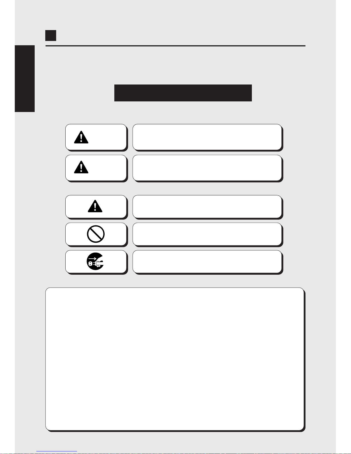
•The following suggestions show the degree of danger and damage caused when the
product is used improperly with the suggestions disregarded.
•The following graphic suggestions describe the types of precautions to be followed.
Indicates a matter of which care should be taken.
Indicates a matter which is forbidden.
Indicates a matter which should be performed
without fail.
2
CAUTION
Indicates a situation where disregarding the
suggestions could result in injury or product
damage.
WARNING
Indicates a situation where disregarding the
suggestions could result in death or serious
injury.
ENGLISH
•In this instruction manual, some procedures require a qualified in-shop maintenance person or
industry specialist. For such instructions, a qualified person must take care of the jobs.
·Otherwise an electric shock, machine trouble, or a serious accident may result.
·Replacing the machine parts, inspecting and maintaining the machines, and troubleshooting must be
assigned only to a qualified in-shop maintenance person or industry specialist. This booklet gives
instructions that hazardous jobs in particular must be handled by an industry specialist.
Qualified in-shop maintenance persons and industry specialist are defined as follows.
Qualified in-shop maintenance persons
·A qualified in-shop maintenance person must have experiences in maintaining amusement machines,
money changers and the like. Under the supervision of an amusement machines shop owner or
manager, he or she routinely assembles, installs, inspects and maintains the amusement machines, or
replaces their component units and consumable parts, in the amusement machines workshop and/or
shop.
Jobs handled by qualified in-shop maintenance persons
·Assembling, installing, inspecting and maintaining amusement machines and money changers, and
replacing their component units and consumable parts.
Industry specialist
·An industry specialist must be engaged in designing, manufacturing, inspecting and servicing amusement
machines. Or he or she must have an education in electrical, electronic and mechanical engineering,
and routinely maintain and repair amusement machines.
Jobs handled by industry specialist
·Assembling and installing amusement machines and money changers, and repairing and adjusting
their electrical, electronic and mechanical component parts.
•
Definitions of qualified in-shop maintenance persons and industry specialist who handle this product.
Page 5
3
Precautions for use
ENGLISH
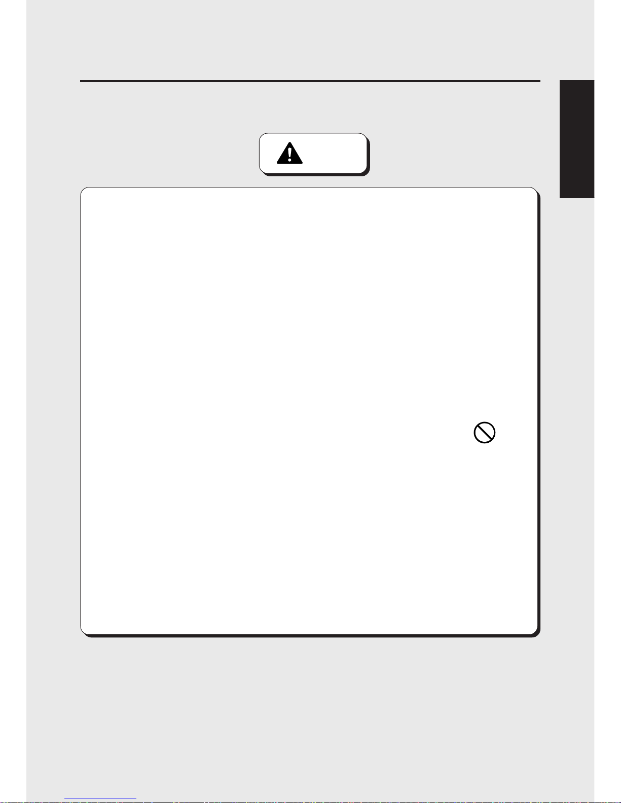
WARNING
•Be sure to follow the installation instructions. Wrong handling may cause a
machine trouble or accident. Contact an industry specialist or your nearest dealer
for installing this kit. (You will be charged.)
•The projector unit has some internal parts with high voltage. Only a qualified
industry specialist is allowed to open the back door of the machine. With this back
door open, be very careful not to touch unnecessary parts.
·Otherwise an accident or electric shock may result.
•Handle this kit with due care when installing it.
·Wrong handling may cause kit trouble or accident.
·Parts inside the PCB unit get hot structurally. Do not touch them until completely cooled
down.
·The PCB unit have some projections on them. Handle the PCB unit carefully not to get
injured.
•Do not leave anything, such as a water- or chemical-containing container, on top of
or close to the kit or the detached PCB unit.
·Electrical shock or damage could be caused by water or foreign matter entering the
inside of the kit.
•Before attaching or detaching the PCB unit, be sure to turn OFF the machine’s power
switch and unplug the power cord.
·Otherwise, a machine trouble or electric shock may result.
•Before installing the PCB unit, clean up the inside of the machine using a vacuum
cleaner or the like.
·If the electrical components are left covered with dust, an electric shock or fire may result.
•In installing the PCB unit in the machine, connect the connectors securely.
·Otherwise, a machine trouble or fire may be caused.
3
Page 6

44
Precautions for use
PRECAUTION
IN HANDLING
•When setting up or handling this product, follow the procedures and instructions set forth in this
manual and perform such work safely.
•Do not remove labels of “WARNING”, “CAUTION”, etc. attached to the product.
•Do not set up or handle this product under conditions equivalent to the condition of “WARNING” or
“CAUTION” specified in this manual.
•If a new owner is to have this product as a result of transfer , etc., be sure to give this manual to the new owner.
•Before removing the PCB unit or installing the kit, put on a wrist band to prevent
static electricity. Do not do this job on a carpet or the like.
·Static electricity may damage the electric parts on the game PC board.
•Do not touch the PCB unit with wet hands.
·Otherwise, a machine trouble or electric shock may result.
•Never disassemble, repair or modify any section other than those specified in this
manual.
·Doing so could result in fire, malfunction or equipment failue.
·Ask your nearest dealer to perform repairing, etc..
· We do not assume any responsibility for any damages that would be caused by
tampering with the kit.
•If by any chance any of the connectors and cables to be connected to the machine
or the PCB unit is found defective, immediately stop using the machine and ask
your nearest dealer to replace the damaged part.
·Using a damaged connectors and cables could result in fire or electrical shock.
ENGLISH
CAUTION
Page 7

5
MEMO
Page 8

6
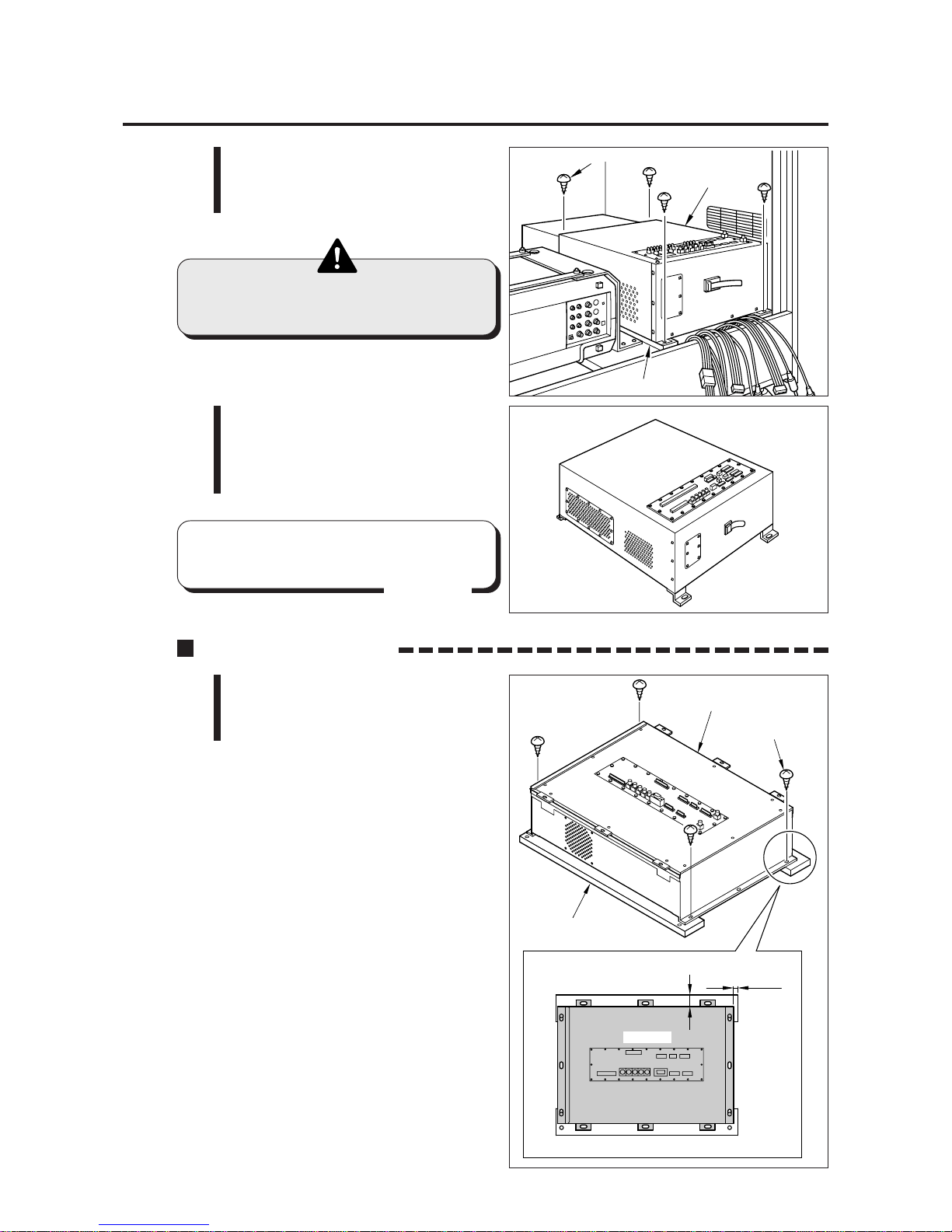
Screws
Back door
2
Removing the PCB unit
•Be sure to ask a qualified industry specialist or your nearest dealer to
replace the PCB unit. (You will be charged.)
•Before removing the PCB unit, be sure to turn OFF the machine’s power
switch and unplug the power cord.
•The projector unit has some internal parts with high voltage. Only a qualified
industry specialist is allowed to open the back door of the machine. With
this back door open, be very careful not to touch unnecessary parts.
•Before installing the PCB unit, clean up the inside of the machine using a
vacuum cleaner or the like.
1 Be sure to turn OFF the machine’s
power switch and unplug the power
cord from the receptacle.
2 Remove the back door of the
projector unit
3 Undo the clamp that secures the
cables on the projector.
4 Undo the clamp off the cables of
the PCB unit, and disconnect all the
connectors.
1 Setting the kit in the machine
3
•In order not to confuse the connectors
later, preferably give the connectors
some identification marks before
disconnecting them.
•The connector lock screws are used
again. Be careful not to lose them.
MEMO
PCB unit
Connectors
Clamp
Clamp
Projector unit
Page 9
7
5 Remove the wood screws and
detach the old PCB unit off the
wooden board.
•Since the PCB unit is heavy, use
due care when handling it.
6 Take out the PCB unit, remove the
two countersunk screws from the
wooden board, and take out the
wooden board.
1 Using the above-mentioned wood
screws, mount the new PCB unit in
position on the wooden board.
1 Setting the kit in the machine
Installing the PCB unit
•Keep the old PCB unit in a safe place
unitil the next-time use.
MEMO
PCB unit
Wooden board
Wood screws
PCB unit (old)
10mm
35mm
PCB unit
Wooden board
PCB unit (new)
Wood screws
Top view
Page 10
8
Power unit
*Screws
Screws
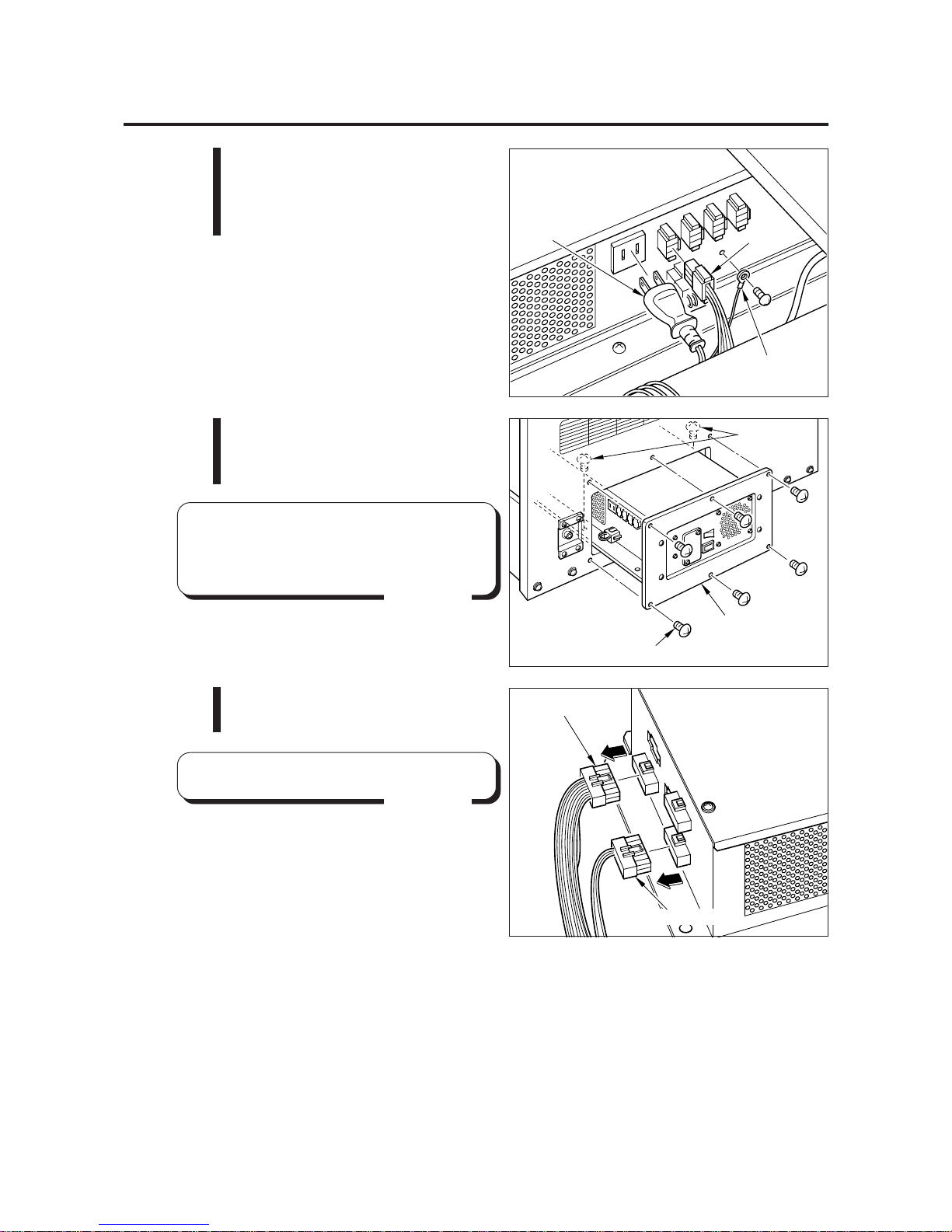
2 Unplug the power plug and
disconnect the connector and
grounding wire, all from the power
unit. See the figure at right.
•There are two more power unit
mounting screws inside the cabinet.
(See the *-marked screws.)
MEMO
3 Remove the screws shown at right.
Draw the power unit halfway also
as shown at right.
4 Disconnect the white and red
connectors from the power unit.
1 Setting the kit in the machine
•Keep all the other connectors intact.
MEMO
Connector
Grounding wire
Power plug
Connector(white)
Connector(red)
Page 11

9
5 Connect the accompanying cables
between the detached connectors
and the power unit connectors.
See the figure at right.
•Be very careful not to confuse the
connectors. A fire may result.
6 Push the power unit back into place with care not to get the cables caught
inside the cabinet. Then fix it with the screws.
7 Reconnect the power plug, connector and grounding wire that were
disconnected in Step 2.
8 Place inside the cabinet the wooden
board that has the new PCB unit
on it. Move the wooden board all
the way to the right.
•Be sure to hold the wooden board
when setting the new PCB unit in
the cabinet.
1 Setting the kit in the machine
9 Finally fix the wooden board with the countersunk screws.
Connector(Red)
Connector(Red)
Connector(White)
Accmpanying cables
Accmpanying cables
Accmpanying cables
(Black/Orange)
Accmpanying cables
(Black/Red)
Connector(White)
Wooden board
PCB unit
Countersunk screws
Page 12

10
1 Reconnect the connectors that were disconnected see the figure below.
2 Secure the cables, loosened in Step 3 (see page 6), again with the clamp.
Tuck the unused cables and excess cables inside the cabinet.
3 Double-check to see if all the connectors are connected as specified.
4 Carry out the “2-1 PCB start-up check (self test)” procedure on page 11 to see
if the PCB unit functions well.
5 Attach the back door back in position on the projector unit.
*1: Be careful not to confuse the networking cables and the monaural
cable. They are all the same in shape and color.
1 Setting the kit in the machine
Reconnecting the connectors
CN5
*1
Monaural cable
(black)
*1
Networking cables
(black)
Audio
cables
CN3
CN6
S1
CN7
S2
S5
S6
CN8
CN9
CN10
S7
S4
S3
CN4
Page 13

11
2-1 PCB start-up check (self test)
•For networking, be sure to connect with the same “RACING JAMTM
CHAPTER II” machine.
•Be sure to check the PCB (self test) before using the machine.
•Before use, be sure to adjust the on-screen display of the projector (refer
to page 15).
•If an abnormality persists or the machine does not operate properly,
immediately turn OFF the power switch, unplug the power cord from the
receptacle and contact your nearest dealer.
2 PCB settings
Result of test
· The steering wheel and other components are automatically repositioned. The
machine then goes to the game mode and the demonstration game gets started.
If test is OK
When the power switch is turned ON after replacement of the PCB unit, the
performance of game Printed Circuit Boards (PCB) is checked automatically and the
result is displayed on the screen.
· “ BAD ” or “HARDWARE ERROR(***)”appears on the screen, and the checking
is repeated.
If “OPTION SETTINGS BACKUP DA TA ERROR.” and “PRESS TEST SWITCH
TO ALL FACTORY SETTINGS.” appear, press the test switch on the service
panel. (The settings made in the manual test will be back to the factory
settings.)
If “RECORD BACKUP DATA ERROR.” and “PRESS TEST SWITCH TO
RECORD DATA CLEAR.” appear, press the test switch on the service panel.
(The course record will be back to the factory setting.)
If “BOOKKEEPING BACKUP DATA ERROR.” and “PRESS TEST SWITCH TO
DATA INITIALIZE.” appear, press the test switch on the service panel. (The
bookkeeping data will be back to the factory setting.)
If an abnormal display continues or the machine does not operate normally,
immediately turn OFF the power switch and contact your nearest dealer.
If any abnormality is detected
Page 14

12
2-2
Correcting the positions of the steering wheel etc.
2 PCB settings
Result of position check
•When the position check is over, the operation mode returns automatically to the
game mode.
The result of check is displayed as follows on the screen.
•Steering wheel abnormal
The message “DEVICE ERROR (STEERING WHEEL)” appears on the screen.
What to do ............The steering wheel control exceeds the correctable range
or the steering wheel reaction device is out of order. Make
the adjustment by referring to “7-5 Replacing and adjusting
the potentiometer” in pages 55 and 56 of the “RACING
JAMTM” Operator’s Manual.
•Hand brake abnormal
The message “DEVICE ERROR (HAND BRAKE)” appears on the screen.
What to do ............ The hand brake control exceeds the correctable range.
Make the adjustment by referring to “7-5 Replacing and
adjusting the potentiometer” in pages 61 to 63 of the
“RACING JAMTM” Operator’s Manual..
•Accelerator abnormal
The message “DEVICE ERROR (ACCEL)” appears on the screen.
What to do ............ The accelerator control exceeds the correctable range.
Make the adjustment by referring to “7-5 Replacing and
adjusting the potentiometer” in pages 57 and 58 of the
“RACING JAMTM” Operator’s Manual..
•Brake abnormal
The message “DEVICE ERROR (BRAKE)” appears on the screen.
What to do ............ The brake control exceeds the correctable range. Make
the adjustment by referring to “7-5 Replacing and adjusting
the potentiometer” in pages 57 and 58 of the “RACING
JAMTM” Operator’s Manual.
•Clutch abnormal
The message “DEVICE ERROR (CLUTCH)” appears on the screen.
What to do ............ The clutch control exceeds the correctable range. Make
the adjustment by referring to “7-5 Replacing and adjusting
the potentiometer” in pages 59 and 60 of the “RACING
JAMTM” Operator’s Manual.
If test is OK
If any abnormality is detected
If any of the above signs is displayed, press the test switch on the service panel to go
to the manual test mode. (The “MAIN MENU” screen shows up.) Then choose “I/O
CHECK” to check the device which shows the error. If the “DEVICE ERROR (
****
)”is
still displayed after the adjustment, the device itself may be in trouble. Immediately
turn OFF the power switch, unplug the power cord and contact your nearest dealer.
If the “GAME MODE” is selected on the “MAIN MENU” screen with some troubles of
any devices, the game may not be played normally.
If an abnormality persists or the machine does not operate properly, immediately turn
OFF the power switch, unplug the power cord from the receptacle and contact your
nearest dealer.
After the self-test, the positions of the steering wheel, hand brake, acceleration
pedal, brake pedal and clutch pedal are corrected automatically.
At this time, the message “DO NOT T OUCH THE CONTROL DEVICE WHEN THE
MACHINE IS BEING INITIALIZED.” appears on the screen. Never touch the
steering wheel, hand brake, acceleration pedal, brake pedal and clutch pedal as
long as this message stays on the screen. The steering wheel makes a few turns
itself clockwise and counterclockwise.
Page 15

13
2 PCB settings
2-3 Adjusting the game environment (manual test)
Manually check the settings for the screen displays and game contents and change
them as required.
Starting the manual test mode
1 Turn ON the power switch.
2 Press the test switch on the service panel during the game mode demo (during
the game mode demo of all the game machines in the case of networking) .
(T urning ON the power switch while holding down the test switch will return all the
present manual test settings to the original factory settings at the time of
shipment.)
·The unit is set in the manual test mode and the main menu is displayed on the
screen.
Main menu screen (basic items)
Selecting each mode
How to select each mode from the main menu
·SELECT --> Move the shift lever up (1, 3 or 5)
or down (2, 4 or R).
·SET --> Press the START button.
After selecting a mode, refer to the page on which that mode is described in details.
Quit the manual test mode
1 Choose the “GAME MODE” from the main menu by the shift lever.
2 Press the START button.
·Then, the screen returns to game mode.
I/O CHECK
SCREEN CHECK
COLOR CHECK
MASK ROM CHECK
C.G. BOARD CHECK
SOUND OPTIONS
GAME OPTIONS
COURSE SETTINGS
COIN OPTIONS
NETWORK OPTIONS
BOOKKEEPING
ALL FACTORY SETTINGS
GAME MODE
PRESS START BUTTON TO EXECUTE
•Checking the controls.
--> Page 14
•Adjusting the on-screen size, etc..
--> Page 15
•Adjusting the display color.
--> Page 15
•Checking the mask ROMs.
--> Page 15
•Checking the C.G. board function.
--> Page 16
•Enters the sound settings.
--> Page 16
•Enters the game settings.
--> Page 17
•Enters the course difficulty levels, etc..
--> Page 17
•Setting the coin options.
--> Page 18
•Sets and checks the network.
--> Page 19
•Displaying the coin data.
--> Page 22
•Returns all the settings to the factory settings.
--> Page 23
•Return to game mode.
MAIN MENU
1
234
5
R
Up
Down
Page 16

14
2 PCB settings
I/O CHECK
•If the steering wheel or the accelerator is not properly adjusted, make the
necessary adjustments while referring to “7-5 Replacing and adjusting the
potentiometer” on pages 55 to 63 of the “RACING JAM
TM” Operator’s Manual.
•The marker position changes to show the input
value.
•Shows the value for steering wheel in decimal
(hexadecimal).
The steering wheel is set properly when the steering
wheel is fully turned clockwise and the red “I” mark
comes to the “RIGHT” position as well as when the
wheel is fully turned counterclockwise and the mark
comes to the “LEFT” position.
•Shows the value for the accelerator pedal [decimal
(hexadecimal)]. if the "I" mark moves to “MIN”
when the accelerator pedal is eleased and to “MAX”
when the accelerator pedal is fully press, the
accelerator pedal is properly adjusted.
•Shows the value for the foot brake unit [decimal
(hexadecimal)].
Make sure the “I” make moves to “MIN” when
the foot brake is released and to “MAX”when the
foot brake is fully pressed.
•Shows the value for hand brake in decimal
(hexadecimal).
The hand brake is set properly when the hand brake
is released and the “I” mark comes to the “MIN”
position as well as when the hand brake is pulled up
and the mark comes to the “MAX” position.
•Shows the value for the clutch pedal [decimal
(hexadecimal)]. if the "I" mark moves to “MIN”
when the clutch pedal is eleased and to “MAX”
when the clutch pedal is fully pressed, the clutch pedal
is properly adjusted.
•Check the steering wheel reaction device by putting
down the shift lever while pressing the START button.
The steering wheel turns automatically
clockwise and counterclockwise by turns during
checking. Then, make sure that the “I” mark moves
accordingly to the right and left on the meter which
shows the value for the steering wheel. Do not touch
the steering wheel while this checking is conducted.
GEAR SHIFT LEVER
1 3 5 UP OFF DOWN OFF
ERROR LEFT OFF RIGHT OFF
2 4 R
STEERING WHEEL
0.0000 (0000)
ACCEL PEDAL
0.0000 (0000)
FOOT BRAKE PEDAL
0.0000 (0000)
HAND BRAKE LEVER
0.0000 (0000)
CLUTCH PEDAL
0.0000 (0000)
LEFT CENTER RIGHT
+---+--------------------------------------------------------+---+
MIN MAX
+---+--------------------------------------------------------+---+
MIN MAX
+---+--------------------------------------------------------+---+
MIN MAX
+---+--------------------------------------------------------+---+
MIN MAX
+---+--------------------------------------------------------+---+
HOLD START BUTTON AND GEAR SHIFT DOWN = ACTIVE STEERING TEST
HOLD GEAR SHIFT UP AND PRESS START BUTTON TO EXIT
I/O CHECK
START BUTTON OFF COIN MECH SWITCH OFF
SERVICE SWITCH OFF TEST SWITCH OFF
Checking the controls
2-4 Mode descriptions
The original factory settings are displayed in green; the changed settings are
displayed in red.
·To change the settings, move the shift lever up or down to select an item, and
press the START button to enter it.
·After the setting change, select “SAVE AND EXIT” and press the START button.
The settings are saved automatically and the screen returns to the main menu.
·If "EXIT" is selected after the modification of the settings, the following message
will appear:
"YOU DID NOT SAVE. DO YOU WANT TO SAVE? YES / NO" Select "YES" or
"NO" by shift lever up or down and set it by pressing the START button.
If "YES" is selected, the new settings will be saved with "NOW SA VING" displayed
and the screen will return to the main menu.
If "NO" is selected, the new settings will not be saved with "NO MODIFICATION"
displayed and the screen will return to the main menu.
•If "FACTORY SETTINGS" is selected and the START button is pressed, all the
settings of the mode will be back to the factory ones.
MEMO
Mode for checking the performance each control.
To return to the main menu screen, hold down the STAR T button and move up the
shift lever.
MEMO
•This screen is just an example.
Page 17

15
2 PCB settings
MASK ROM CHECK
Checking the mask ROMs
The mask ROMs are checked one by one.
If the ROM is not in trouble, “ OK ” is displayed.
If anything unusual is found, “BAD ” appears. Once in this mode, this checking gets
started automatically. To return to the main menu screen, press the ST ART button.
• If “BAD” appears, immediately turn OFF the power switch, unplug the power cord
from the receptacle and contact your nearest dealer.
SCREEN CHECK
Mode for checking the screen display.
Using the LCD projector, adjust the display size, display position and other factors
so that the marks on the screen up to the screen edges. (See page 72 of the
“RACING JAM
TM” Operator’s Manual)
To return to the main menu screen, press the START button.
Adjusting the on-screen size, etc.
COLOR CHECK
Mode for checking the display color.
Make the adjustment using the LCD projector adjusting remote controller so that the
colors of the color bars should appear properly graduated and the background should
become black sufficiently. (See page 72 of the “RACING JAM
TM” Operator’s Manual)
To return to the main menu screen, press the START button.
Adjusting the display color
PRESS START BUTTON TO EXIT
SCREEN CHECK
•Marks on the outer frame.
Page 18

16
2 PCB settings
PRESS START BUTTON TO EXIT
C.G.BOARD CHECK
•The “RACING JAMTM CHAPTER II ” logo is
shown before the cubes.
•Two cubes are rotating and entangled with
each other.
C.G. BOARD CHECK
Checking the C.G. board function
Mode for checking the function of the C.G. board.
Observe the screen in this mode to make sure that the C.G. board is functioning well.
To return to the main menu screen, press the START button.
SOUND IN ATTRACT MODE
ALL THE TIME
VOLUME SETTING 20
SCALE CHECK
B.G.M IN GAME MODE
ON
FACTORY SETTINGS
SAVE AND EXIT
EXIT
SOUND OPTIONS
GEAR SHIFT UP/DOWN = SELECT OPTION
PRESS START BUTTON = MODIFY SETTING
•Turns on and off the demo play sound.
·ALL THE TIME .............. Sound always on.
·
ONCE EVERY 4 CYCLES
......... Sound on every
4 cycles.
·COMPLETE OFF ……… Sound always off.
•Adjusts the sound effect and other volume
settings in steps from 0 (mute) to 30 (maximum).
·To raise the sound level, hold down the START
button and move up the shift lever.
·To lower the sound level, hold down the START
button and move down the shift lever.
•You will hear a do-re-mi...do musical scale from
the left speaker first and then from the right
speaker, which is repeated twice.
The second round is given acoustic echo.
•Sets to give background music while the game
is being played.
·ON.....Background music heard
·OFF...Background music not heard
Background music only during the race.
Not effective for demo-game background
music, sound and other sound effects.
•Returns all the settings to the factory settings.
SOUND OPTIONS
This screen is used to make sound settings and to check them.
Move the shift lever up or down to select an item, and press the START button to
enter it. To return to the main menu screen, select “SAVE AND EXIT” or “EXIT” and
press the START button.
Enters the sound settings
•This screen is just an example.
Page 19

17
2 PCB settings
GAME OPTIONS
This screen is used to make game settings and to check them.
Move the shift lever up or down to select an item, and press the START button to
enter it. To return to the main menu screen, select “SAVE AND EXIT” or “EXIT” and
press the START button.
Enters the game settings
•When networking the machines, be sure to set all the machines to the
same settings.
SPEED METER DISPLAY
km/h
MOTOR POWER LEVEL
MEDIUM
COURSE RECORD SAVING
ENABLE
BONUS CREDIT for WINNER
DISABLE
CLEAR RANKING DATA
FACTORY SETTINGS
SAVE AND EXIT
EXIT
GEAR SHIFT UP/DOWN = SELECT OPTION
PRESS START BUTTON = MODIFY SETTING
GAME OPTIONS
•Selects the speed meter display
[km/h] or [MPH].
•Sets the return force of the steering wheel.
·OFF ......................... No return force
·POWERLESS .......... Weak
·MEDIUM ................. Standard
·POWERFULL .......... Strong
•Saves a course record.
Select "DISABLE" and the course record is not
saved nor initialized.
•In a network play with 4 or more cars, the
first-place winner gets one bonus credit added.
•Erases the ranking data.
•Returns all the settings to the factory settings.
COURSE SETTINGS
This screen is used to make course settings and their difficulty levels.
Move the shift lever up or down to select an item, and press the START button to
enter it. To return to the main menu screen, select “SAVE AND EXIT” or
“EXIT” and press the START button.
Enters the course difficulty levels, etc. settings
•When the number of laps for a course has been set and saved, the course record
of that course will be initialized.
CIRCUIT BANK
CIRCUIT NIGHT
CROSS ROAD
WINDING ROAD
FACTORY SETTINGS
SAVE AND EXIT
EXIT
4/MEDIUM
5/MEDIUM HARD
8/HARDEST
7/VERY HARD
DIFFECULTY LEVEL
NUMBER of LAPS
3
3
3
GEAR SHIFT UP/DOWN = SELECT OPTION
PRESS START BUTTON = MODIFY SETTING
COURSE SETTINGS
•Sets a difficulty level (from the 8 levels).
1/EASIEST Easier
2/VERY EASY
3/EASY
4/MEDIUM---------------
Standard
5/MEDIUM HARD
6/HARD
7/VERY HARD
8/HARDEST Harder
•Sets the number of laps (2 to 7).
•Returns all the settings to the factory settings.
•This screen is just an example.
MEMO
•This screen is just an example.
Page 20

18
2 PCB settings
The relationship between the number of coins and the number of credits.
SETTING
COIN(S)
CREDIT(S)
1
1
1
2
1
2
3
1
3
4
1
4
5
1
5
6
1
6
7
1
7
8
2
1
9
2
3
10
2
5
11
3
1
12
3
2
13
3
4
14
4
1
15
4
3
16
4
5
17
5
1
18
5
2
19
6
1
20
6
5
SETTING
COIN(S)
CREDIT(S)
21
7
1
22
7
2
23
8
1
24
8
3
25
9
1
26
10
1
27
11
1
28
12
1
29
13
1
30
14
1
31
15
1
32
16
1
FREE PLAY NO
COIN MECHANISM INDEPENDENT
COIN SLOTS 2 COINS 1 CREDIT
FACTORY SETTINGS
SAVE AND EXIT
EXIT
GEAR SHIFT UP/DOWN = SELECT OPTION
PRESS START BUTTON = MODIFY SETTING
COIN OPTIONS
•Always keep it set to INDEPENDENT.
•Sets the number of credits for the coin.
(Make the settings referring to the table below.)
•Returns all the settings to the factory settings.
•Selects a free play.
YES......Available for free play.
NO........Not available for free play.
COIN OPTIONS
This screen is used to make coin settings and to check them.
Move the shift lever up or down to select an item, and press the START button to
enter it. To return to the main menu screen, select “SA VE AND EXIT” or “EXIT” and
press the START button.
Setting the coin options
•The coin setting options are not displayed when “FREE PLAY” is set to
“YES”. In such case, remember the game will be free.
•This screen is just an example.
Page 21

19
NETWORK OPTIONS
Sets and checks the network.
Move the shift lever up or down to select an item, and press the START button to enter
it. To return to the main menu screen, select “SAVE AND EXIT” or “EXIT” and press
the START button.
Sets and checks the network
•If any of the three items responds incorrectly, it indicates possible
communication malfunction. Take measures while referring to “2-5
Measures to be taken when there is a network abnormality” on page 24.
•If the machine still shows the same trouble or any troubles that are not
discussed in this manual, immediately turn OFF the power switch, unplug
the power cord and contact your nearest dealer.
·Check that the “I” mark in the STATUS column is moving from the left to the right at a fixed
speed.
·Check that the value in the ERROR column is below “10” after one minute.
·Check that the value in the DOWN column does not change from “0”.
Check items (Watch the screen for longer than 1 minute and make sure the following 3 conditions are met.)
THIS BOARD-ID IS 8
ERROR DOWN STATUS
PRESS START BUTTON = EXIT
NETWORK CHECK
ID No.1 0 0 DNC
ID No.2 0 0 DNC
ID No.3 0 0 I
ID No.4 0 0 DNC
ID No.5 0 0 I
ID No.6 0 0 DNC
ID No.7 0 0 DNC
ID No.8 0 0 DNC
•Shows “Network ID” of the connected
machine. (Number from 1 to 8)
•The “I” mark is moving from left to right when
the machine is networked.
•“DNC” (Did Not Connect) appears if the
machine is not networked.
NETWORK CHECK select the following screen appears.
When networking the machines, be sure to check their networking status on this
screen. To return to the “NETWORK OPTIONS” screen, press the STAR T button.
•Sets a network ID.
Enters different numbers (machine numbers) to
the machines that will be networked.
(Same numbers are not allowed.)
•Sets the communication wait time.
Choose from 4, 8, 12, 16, 20, 24, 28 and 32.
•Sets the communication-play course decision
by majority or by individual.
·DECIDED by MAJORITY...Course decided by
majority
·DECIDED INDIVIDUALLY...Course not decided
by majority
•This mode is used to check the network condition.
(See the figure below)
•This mode is used to automatically configure the
settings of the networked machined.
(See page 21)
•Returns all the settings to the factory settings.
NETWORK ID
2
GAME JOINING PERIOD
12 counts
COURSE SELECTION
DESIDE by MAJORITY
NETWORK CHECK
NETWORK CONFIGURATION
FACTORY SETTINGS
SAVE AND EXIT
EXIT
GEAR SHIFT UP/DOWN = SELECT OPTION
PRESS START BUTTON = MODIFY SETTING
NETWORK OPTIONS
•This screen is just an example.
•This screen is just an example.
2 PCB settings
Page 22

20
2 PCB settings
Screen display when game machines are networked
THIS BOARD-ID IS 1
ERROR DOWN STATUS
PRESS START BUTTON = EXIT
NETWORK CHECK
ID No.1 0 0 I
ID No.2 0 0 I
ID No.3 0 0 DNC
ID No.4 0 0 DNC
ID No.5 0 0 DNC
ID No.6 0 0 DNC
ID No.7 0 0 DNC
ID No.8 0 0 DNC
THIS BOARD-ID IS 2
ERROR DOWN STATUS
PRESS START BUTTON = EXIT
NETWORK CHECK
ID No.1 0 0 I
ID No.2 0 0 I
ID No.3 0 0 DNC
ID No.4 0 0 DNC
ID No.5 0 0 DNC
ID No.6 0 0 DNC
ID No.7 0 0 DNC
ID No.8 0 0 DNC
Screen for player 1
Screen for player 2
•Four game machines are networked
Screen for player 2
Screen for player 3
Screen for player 4
THIS BOARD-ID IS 1
ERROR DOWN STATUS
PRESS START BUTTON = EXIT
NETWORK CHECK
ID No.1 0 0 I
ID No.2 0 0 I
ID No.3 0 0 I
ID No.4 0 0 I
ID No.5 0 0 DNC
ID No.6 0 0 DNC
ID No.7 0 0 DNC
ID No.8 0 0 DNC
THIS BOARD-ID IS 2
ERROR DOWN STATUS
PRESS START BUTTON = EXIT
NETWORK CHECK
ID No.1 0 0 I
ID No.2 0 0 I
ID No.3 0 0 I
ID No.4 0 0 I
ID No.5 0 0 DNC
ID No.6 0 0 DNC
ID No.7 0 0 DNC
ID No.8 0 0 DNC
THIS BOARD-ID IS 3
ERROR DOWN STATUS
PRESS START BUTTON = EXIT
NETWORK CHECK
ID No.1 0 0 I
ID No.2 0 0 I
ID No.3 0 0 I
ID No.4 0 0 I
ID No.5 0 0 DNC
ID No.6 0 0 DNC
ID No.7 0 0 DNC
ID No.8 0 0 DNC
THIS BOARD-ID IS 4
ERROR DOWN STATUS
PRESS START BUTTON = EXIT
NETWORK CHECK
ID No.1 0 0 I
ID No.2 0 0 I
ID No.3 0 0 I
ID No.4 0 0 I
ID No.5 0 0 DNC
ID No.6 0 0 DNC
ID No.7 0 0 DNC
ID No.8 0 0 DNC
•Two game machines are networked
Screen for player 1
•This screen is just an example.
Page 23

21
2 PCB settings
Setting modes which can be unified are as follow:
•“SOUND OPTIONS” ......... (See page 16)
•“GAME OPTIONS”............ (See page 17)
•“COURSE SETTINGS” ..... (See page 17)
•“COIN OPTIONS” ............. (See page 18)
•If the network communication settings have not been made normally in the above
steps 5 to 6, make the same settings for all the machines one by one.
If the network play still fails, refer to pages 24 and 25.
MEMO
NETWORK CONFIGURATION
This mode is to automatically configure a group of already networked machines to
the settings of a machine that has been connected to the group.
To return to the “NETWORK OPTIONS” screen, press the START button.
Configuring various settings
1. Make sure the networking functions well in the “NETWORK CHECK” mode.
2. All the machines which are connected to the network are displayed on the “MAIN
MENU” screen for the manual test.
3. Set “SOUND OPTIONS”, “GAME OPTIONS”, “COURSE SETTINGS” and “COIN
OPTIONS” for only one set of machine among the others connected to the net
work. (Do not operate the other machines for setting.)
4. When the setting is finished, select the “NETWORK OPTIONS” from the “MAIN
MENU” screen only for the machine for which the above setting 3 was made. Then
select the “NETWORK CONFIGURATION” and press the START button. Make
sure the message “PRESS TEST SWITCH TO START” appears on the screen.
Press the test switch on the service panel of the machine. “CONFIGURATION
START” appears on the screen instead.
5. Make sure all the other machines networked are automatically brought in the
“NETWORK CONFIGURA TION” mode. Then “COMPLETE” appears on the screen.
6. To return to the “NETWORK OPTIONS” screen, press the START button of the
machine for which the above setting 3 was made. (For all the other machines, the
“MAIN MENU” screen shows up.)
Organizing the machine settings being networked.
Take the following steps to configure the settings using the communication function.
1 2 3 4 5 6 7 8
Auto setting
Setting
Page 24

22
When the time has been set on the “CLOCK SET UP” screen, the following
BOOKKEEPING screens show up. Move the shift lever upward and press the
START button, and the total coin data is cleared.
To return to the main menu screen, press the START button.
•This screen is just an example.
BOOKKEEPING
In this mode, the total data on the number of coins put into the machine is displayed.
If the time is preset in this mode, the total data on the number of coins put into the
machine can be viewed by coin slot.
To return to the main menu screen, move the shift lever downward and press the
START button.
Displaying the coin data
•The above setting, once made, is not displayed on the screen until the data is
cleared. If the current time is not set, the coins that have been put in the
machine will not be totaled nor displayed.
MEMO
•This screen is just an example.
2 PCB settings
GEAR SHIFT UP TO CURSOR MOVE
AND DOWN TO MODIFY VALUE
PRESS START BUTTON TO TIME SET
HOLD GEAR SHIFT UP AND PRESS START BUTTON TO EXIT
BOOKKEEPING
CLOCK SET UP
CURRENT 15:47:52
SET TO 0:47:52
•Displays the current time in the 24-hour system.
(15 hours, 47 minutes, 52 seconds)
•Adjusts to a desired time setting.
Move the shift lever upward and select an item.
Move the shift lever downward to set to the time.
·Setting the time ............. Press the START button.
·Canceling the time ........ With the shift lever upward,
press the START button.
GEAR SHIFT UP TO COIN DATA OF 51 WEEKS
HOLD GEAR SHIFT DOWN AND PRESS START BUTTON TO DATA CLEAR
PRESS START BUTTON TO EXIT
BOOKKEEPING
TOTAL COINS 1978
COIN DATA OF LAST 7DAYS
TODAY
YESTERDAY
-2DAY
-3DAY
-4DAY
-5DAY
-6DAY
LAST 7DAYS AVERAGE
0
0
0
0
1
0
0
0
0
0
0
0
1
0
0
0
•Total number of coins after the time being set.
•Number of coins of today.
•Number of coins of yesterday.
•Number of coins of 2 days ago.
•Number of coins of 3 days ago.
•Number of coins of 4 days ago.
•Number of coins of 5 days ago.
•Number of coins of 6 days ago.
•Average number of coins of last 7 days.
Page 25

23
When the shift lever is moved downward on the “COIN DATA OF LAST 7 DAYS”
screen, shown on the preceding page, the past 51-week coin data is displayed in
weekly totals. Move the shift lever upward and press the START button, and the
total coin data is cleared. To return to the main menu screen, press the START
button.
•This screen is just an example.
•When the data is cleared on this screen and then “BOOKKEEPING” is selected,
the “CLOCK SETUP” screen shows up. Make the time setting to get the coin
totalization started.
MEMO
2 PCB settings
GEAR SHIFT UP TO COIN DATA OF LAST WEEK
HOLD GEAR SHIFT DOWN AND PRESS START BUTTON TO DATA CLEAR
PRESS START BUTTON TO EXIT
BOOKKEEPING
COIN DATA OF LAST 51 WEEKS
-01:XXXX -02:XXXX -03:XXXX -04:XXXX
-05:XXXX -06:XXXX -07:XXXX -08:XXXX
-09:XXXX -10:XXXX -11:XXXX -12:XXXX
-13:XXXX -14:XXXX -15:XXXX -16:XXXX
· · · ·
· · · ·
· · · ·
-41:XXXX -42:XXXX -43:XXXX -44:XXXX
-45:XXXX -46:XXXX -47:XXXX -48:XXXX
-49:XXXX -50:XXXX -51:XXXX
•Displays the total data for the period of 51 weeks ago
up to one week ago.
ALL FACTORY SETTING
Mode for Returning all the settings to the factory settings.
In this mode, all the settings but the “BOOKKEEPING” settings on the main menu
will be back to the factory ones. Now “DISABLE” is shown at the “COURSE
RECORD SAVING” option in the “GAME OPTIONS” screen. Select “ENABLE” to
initialize this setting. (See page 17.)
Returns all the settings but the network settings to factory ones
Page 26

24
The “NETWORK ERROR” message appears on the screen after the power is
turned ON.
Symptom 1
2-5 Measures to be taken when there is a network abnormality
If the “NETWORK ERROR” message appears, if any item responds incorrectly in the
network communication check described on pages 19 and 20, or if the projector
displays differ from the specified ones, take the following measures.
•If the machine still shows the same trouble or any troubles that are not
discussed in this manual, immediately turn OFF the power switch, unplug
the power cord and contact your nearest dealer.
Possible causes and measures to be taken
Possible causes
Measures
•The “Network ID” settings are improper.
•The networking cable is in trouble.
•An unnecessary networking cable is
connected with the pin jacks of the first
and last machines.
·Readjust the “Network ID” settings on
the “NETWORK OPTIONS” screen in
the manual test mode. (See page 19)
·Reconnet the networking cable
properly between the machines.
·Replace the networking cable with new
one.
·Disconnect the network cable frpm
those pin jacks. (see page 26 of the
“RACING JAM
TM” Operator’s Manual.)
NETWORK ERROR
CHECK PLAYER MACHINE NUMBER
IN THE NETWORK OR
CHECK NETWORK CABLES
THIS MACHINE'S CAR No.1
•Shows the “Network ID” of game machine.
(A number for 1 to 8)
2 PCB settings
Page 27

25
The “NETWORK ERROR” message appears on the screen during playing.
Symptom 2
Possible causes and measures to be taken
Possible causes Measures
•One of the networking cable has been
disconnected from during play.
•One of the networking cable has been
internally broken or broken.
•The test switch (on the service panel)
of one of the networked game
machines has been pressed.
•The test switch should pressed
during the game demo of all
the networked game machines.
•The settings of the manual test mode
are different between the networked
machines.
·Configure the settings of all the
machines referring to “NETWORK
CONFIGURATION” (see page 21).
NETWORK ERROR
CALL ATTENDANT
2 PCB settings
·1.Turn OFF the power switch.
2.Connect the networking cable properly.
3.Turn ON the power switch.
·Replace the networking cable with new
one.
Y ou can also use commercially-sold
video cable (75 3C-FV) having a
length of 2m(78.74in) or less.
·1.Turn OFF the power switch of all the
networked game machines.
2.Close the maintenance door.
3.Turn ON the power switch.
()
Page 28

26
Replacing the title panel and labels
•Before replacing the title panel, be sure to turn OFF the machine’s power
switch and unplug the power cord from the receptacle.
Part #
Quantity
RemarksPart name
No.
1
2
3
4
5
PANEL, TITLE
LABEL, PLAYING / UB
LABEL, SIDE
LABEL, SERIAL / UA
LABEL, RATING
1
1
2
1
2
0000050220
0000050221
0000050212
0000053175
0000032845
Title panel
How to play (common for right and left)
How to play (common for right and left)
Model and Power label
Rating label
3 Replacing the labels and others
3 Apply the accompanying side label
on the lower triangular area of the
existing side label. Cut off excess
parts of the new label according to
the side panel.
5 Apply this label on the top of the coin
door unit.
1 Remove the screws and replace
the title panel with the new one.
(See page 52 of the “RACING JAMTM”
Operator’s Manual)
2 Apply the accompanying “HOW TO
PLAY” labels on the existing ones.
5 First replace the title panel
and then apply this label.
4 Apply the accompanying labels over
the existing ones.
Page 29

27
4 How to play
The “RACING JAMTM CHAPTER II” virtual-reality racing game, with its high-quality graphics, provides for
unprecedented realism and sense of speed.
The full-scale race driving game also gives you the thrill of car racing such as drifting, counter-steering, load
center shift at cornering, spin turning and other actions.
How to play
1 Put a coin in the slot.
The “COURSE SELECT” screen appears.
2 Select one out of the following courses using the steering wheel.
Step on the acceleration pedal to enter the selection.
•Course selection
•Beginners’ course
·BANK ........................................................... High-speed circuit racecourse with huge
bank corners one after another.
·NIGHT ..........................................................High-speed city road course in a
nighttime setting partially provided with
the opposite lane.
•Medium-level course
·CROSS ROAD ............................................. Circuit racecourse in a thrilling
arrangement of crossroads, merging
traffic and jumping blocks.
•Advanced level course
·Winding ........................................................ Circuit racecourse dotted with tight
hairpin curves.
3 On the “CAR SELECT” screen, select one of the 18 different-performance machines in
existence. Use the steering wheel to select a machine, and step on the acceleration pedal
or press the start button to enter the choice.
4 On the “TRANSMISSION SELECT” screen, choose from the automatic and manual
transmissions. Use the steering wheel to select a type of transmission, and step on the
acceleration pedal or press the start button to enter the choice.
•Transmission selection
·Automatic operations ................................... No shifting is needed during the play.
·Manual operations........................................Shifting is needed.
5 When all the above selections are made, their results are displayed on the screen. If there
are two or more other communication players, the course will be decided by majority.
You cannot join the “RACING JAM
TM CHAPTER II” game halfway.
(Beginners’ circuit A)
(Beginners’ circuit B)
Joining the game halfway
Page 30

28
MEMO
Page 31

29
5 Wiring diagram
5 Wiring diagram
 Loading...