

Page 1
KOMPERNASS GMBH · BURGSTRASSE 21 · D-44867 BOCHUM
www.kompernass.com
ID-Nr.: KH1150-12/06-V1
UK
IB_KH1150_E2731_UK_V1.qxd 15.01.2007 14:46 Uhr Seite 1
Page 2
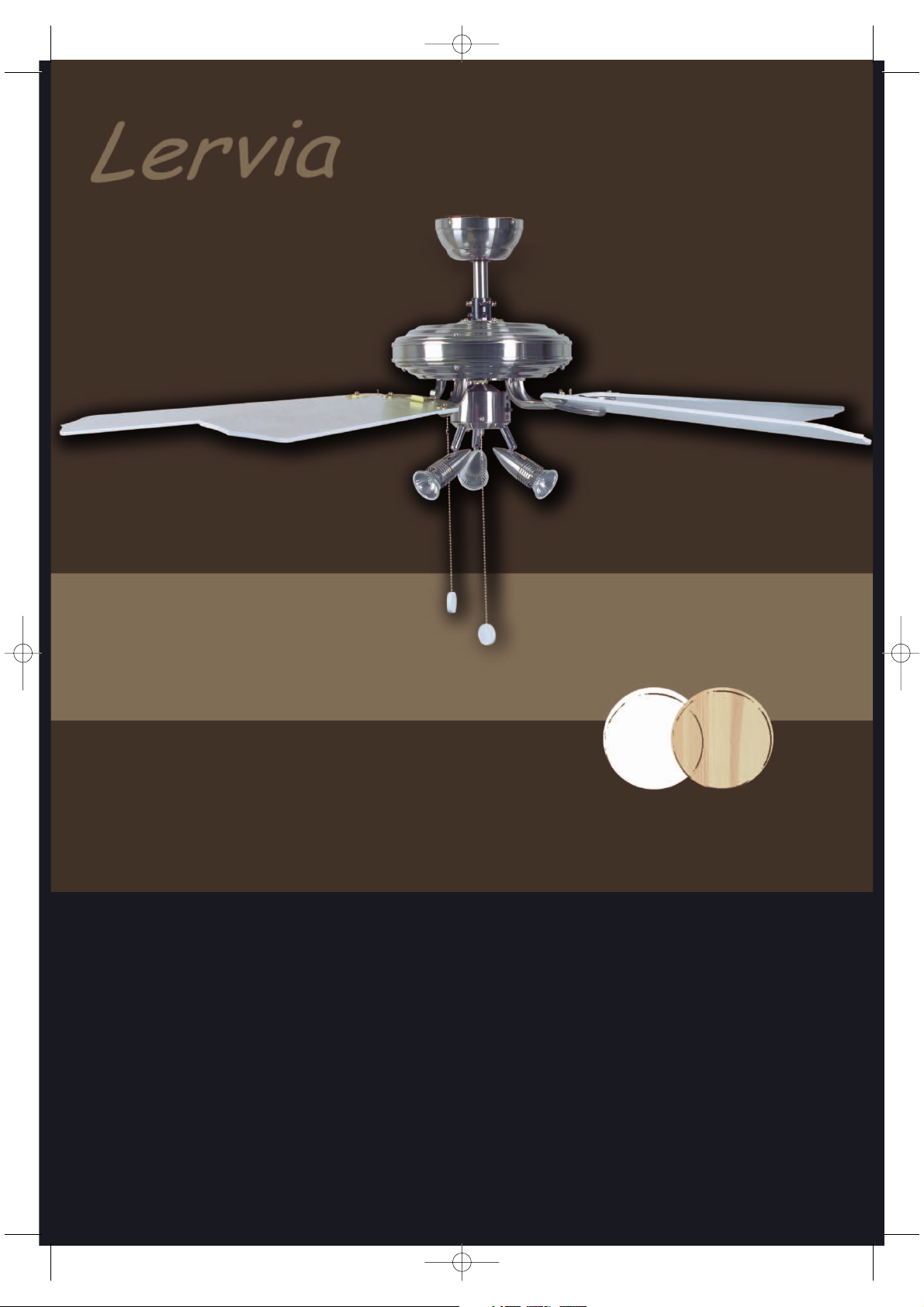
Ceiling Fan KH 1150
Operating Manual
IB_KH1150_E2731_UK_V1.qxd 15.01.2007 14:46 Uhr Seite 2
Page 3
IB_KH1150_E2731_UK_V1.qxd 15.01.2007 14:47 Uhr Seite 3
Page 4
A
G
F
D
E
C
B
H
I
J
K
L
IB_KH1150_E2731_UK_V1.qxd 15.01.2007 14:47 Uhr Seite 4
Page 5
3
Content
1 Safety Instructions ........................................................................................................................................................4
2 Proper Use....................................................................................................................................................................5
3 Product Overview..........................................................................................................................................................5
4 Product Description ......................................................................................................................................................6
5 Guide.............................................................................................................................................................................6
6 Installing the Ceiling Fan...............................................................................................................................................7
6.1 Installing the Blade mounts (J) ............................................................................................................................7
6.2 Installing the Extension Rod (B) ..........................................................................................................................7
6.3 Installing the Light Module (E) .............................................................................................................................9
6.4 Removing the Transport Protection.....................................................................................................................9
6.5 Installing the Blades (H).....................................................................................................................................10
6.6 Hanging the Fan ................................................................................................................................................10
7 Operation ................................................................................................................................................................... 12
7.1 Setting the Speed ............................................................................................................................................ 12
7.2 Setting the Direction..........................................................................................................................................12
8 Cleaning ..................................................................................................................................................................... 12
9 Troubleshooting...........................................................................................................................................................13
10 Warranty and Service..................................................................................................................................................14
11 Technical Data............................................................................................................................................................ 14
12 Importer.......................................................................................................................................................................14
13 Disposal ......................................................................................................................................................................14
IMPORTANT:
Read these instructions and keep them for future reference.
Always follow the safety instructions!
Study the instructions for installation and use before using the fan.
IB_KH1150_E2731_UK_V1.qxd 15.01.2007 14:47 Uhr Seite 3
Page 6
4
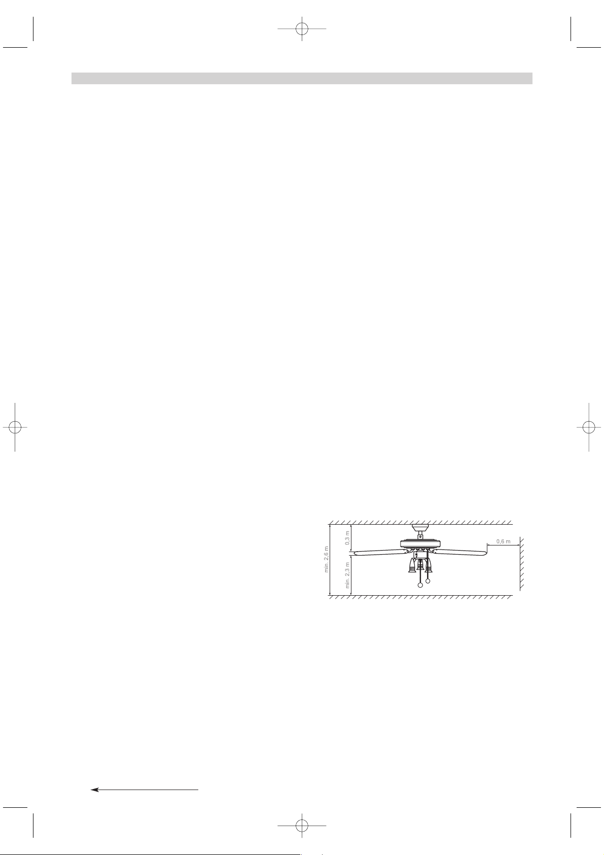
Fig. 1: Minimum distances for the ceiling fan
1 Safety Instructions
DANGER:Always follow the safety instructions
below.
Otherwise, there is a significant risk of
accidents.
Danger of electric shock
• Only a qualified electrician may connect the device to a properly installed and earthed power line with a mains voltage
from 220 - 240 V~ at 50 Hz.
• Never submerse the device in liquid, never subject it to
moisture and never use it outdoors. Should liquid nevertheless enter the device housing, disconnect the device
from the power source, for instance by removing the
associated building fuse or switching the corresponding
circuit breaker (off position) in the fuse box.
• Do not kink or crush the power cord.
• If the power supply wire or the device housing are
damaged, you must have the device repaired by an expert
before using it again. You may not open the device housing.
In this case, the device is not safe and the warranty is
voided.
Fire hazard
• Never leave the appliance unattended whilst in use.
• Never hange the device in the vicinity of heat sources.
• Do not connect the ceiling fan through a dimmer switch.
Use only the pull chain provided for changing the rotation
speed.
Injury hazard
• Never allow children to use the device without adult supervision. Explain to children the dangers of the device.
• The minimum distance from the tips of the blades to the
floor must be 2.30 m when installed. The distance between
the blades and the ceiling must be at least 0.30 m. The side
distance to room walls or obstructions must be at least 0.60
m (see Fig. 1).
• No obstructions may be located within the rotation range of
the device.
• The device must be securely fastened to the room ceiling.
The ceiling, pins and screws must be capable of supporting
the additional load produced by the rotation of the device. If
necessary, seek advice at a building supplies store
regarding the mounting of the ceiling fan.
Suffocation hazard
• The device may not be operated in combination with an oil
or gas oven or heater. Exception: the smoke outlet has been
inspected and approved by an expert in consideration of the
fan operation..
IB_KH1150_E2731_UK_V1.qxd 15.01.2007 14:47 Uhr Seite 4
Page 7

5
2 Proper Use
The ceiling fan serves exclusively for promoting circulation.
This ceiling fan is intended exclusively for use in private
households. Observe all information in this installation and
operating manual, in particular the safety instructions. Any
other use is considered improper use.
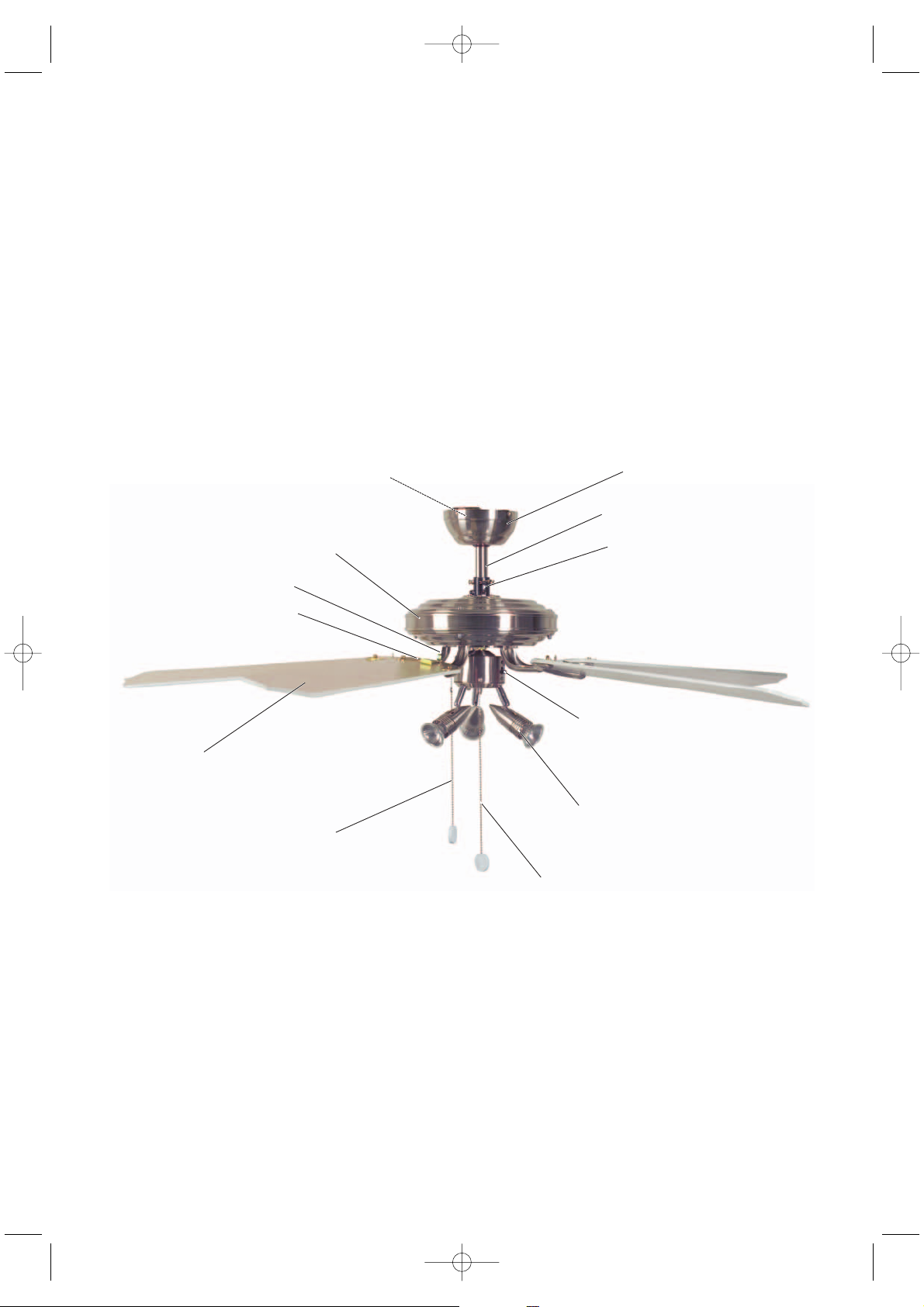
3 Product Overview
A Casing
B Extension rod (2 variants)
C Connector
D Sliding switch for changing the direction
E Light module with 3 bulbs (incl. 3 halogen light bulbs)
F Pull chain for the light
G Pull chain for changing the speed
H Blades (5 pcs.)
I Blade attachment (5 pcs.)
J Blade mount (5 pcs.)
K Motor housing
L Installation plate
IB_KH1150_E2731_UK_V1.qxd 15.01.2007 14:47 Uhr Seite 5
Page 8
6
4 Product Description
The KH 1150 ceiling fan has three speed levels that are controlled with the pull chain. The direction can be changed with
a switch, allowing the fan to blow air downward or draw it
up. In addition, the fan is equipped with a light with 3 halogen
bulbs; the light is switched on and off with a separate pull
chain.
5 Guide
Section 6 describes the installation and Section 7 describes
the basic operation of the KH 1150 ceiling fan.
Read these sections carefully in order to perform the
installation quickly and properly and to understand all the
functions of the fan.
The following signal words and symbols are used:
DANGER
Warns against possibly serious or fatal injuries
WARNING
Warns against possible minor injuries or possible material
damage
CAUTION
Warns against possible defects or destruction of the product
IMPORTANT / NOTE
Provides important or useful information
IB_KH1150_E2731_UK_V1.qxd 15.01.2007 14:47 Uhr Seite 6
Page 9
7
6 Installing the Ceiling Fan
WARNING: Follow the safety instructions (see
Section 1) to avoid injuries or damage as a result of
installation errors. Do not use the fan if it is damaged.
NOTE: The letters in parentheses refer to the figure
in Section 3 "Product Overview".
Required Tools
Phillips head screwdriver
Open-jawed spanner 8 mm
6.1 Installing Blade mounts (J)
1 Select the desired decor: wood grain or white surface.
Lay out the blades so that the desired decor faces down.
2 Run the lock pins of a blade mount (J) through the 3
openings of a blade (H) from below. Position the blade
attachment (I) and push in the direction of the arrow (see
Fig.). The spring clip must snap in and secure the middle
pin (see Fig.: circle). Mount all blades in the same way.
6.2 Installing the Extension Rod (B)
1a Long rod with plastic mount:
Step 1: Loosen the side locking pin on the extension rod
(see Fig.: circle).
Step 2: Slide the mount downward until the lock pin is
exposed.
Step 3: Pull out the lock pin.
1
2
3
IB_KH1150_E2731_UK_V1.qxd 15.01.2007 14:47 Uhr Seite 7
H
I
J
Page 10
8
1b If you would like to use the short extension rod, pull the
mount entirely off the long rod and slide it about halfway
onto the short rod, as shown.
2 Step 1: Loosen the side screws of the connector (C) so
that the extension rod can be inserted.
Step 2: Remove the pins of the connector: Pull out the
linch pin.
Step 3: Remove the pin.
3 Pull the cable through the casing and place the casing
onto the motor housing over the connector.
4a Step 1: Long extension rod: Pull the cable through,
then insert the extension rod into the connector.
Step 2: Install the lock pins of the connector.
Step 3: Insert the linch pin.
Step 4: First tighten both screws evenly at the same time
until hand-tight, then screw them in tightly with
the screwdriver.
4b Short extension rod: After pulling the cable through
(see 4a, substep 1), you must first perform the
following installation step 5. Then perform substeps 2
to 4 under 4a.
5 Install the pin and mount in reverse order from that
described in step 1a and screw the locking screw into
the threading of the extension rod.
1
2
3
1
3
4
2
DANGER: Damaged cables lead to short-
circuits. In such cases, touching the fan could be lifethreatening!
Do not damage the cable when inserting the pin!
IB_KH1150_E2731_UK_V1.qxd 15.01.2007 14:47 Uhr Seite 8
C
Page 11

9
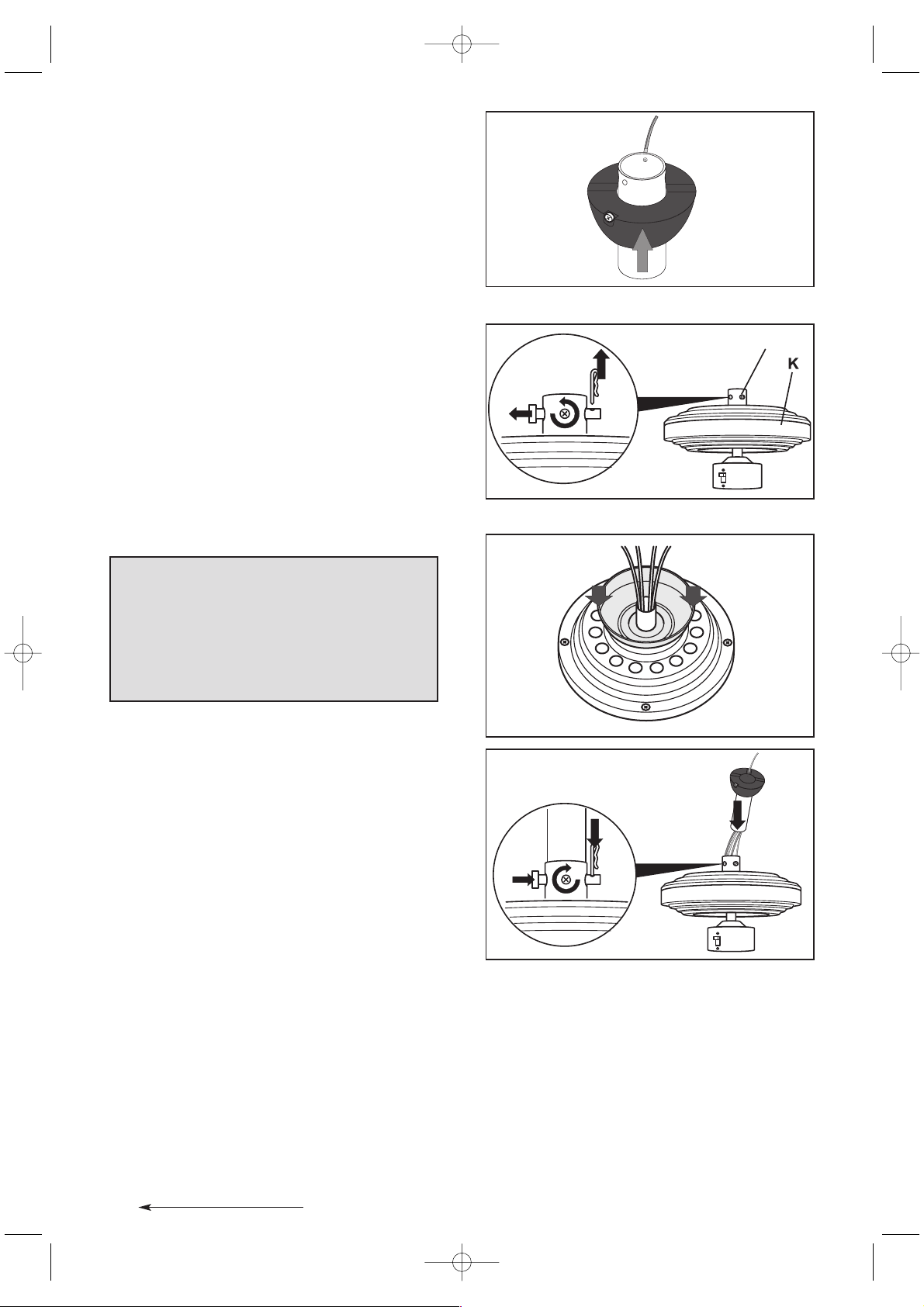
6.3 Installing the Light Module (E)
1 Remove the three screws with lock washers from the light
module (E).
2 Connect the cable plug of the light module to the socket
on the fan.
3 Insert the light into the motor housing, making certain that
the opening is located under the direction switch (see Fig.:
circle).
4 Screw the light module in firmly with the 3 screws and lock
washers.
6.4 Removing the Transport Protection
1 Unscrew the 3 screws of the transport protection elements
on the motor housing (K).
2 Remove the screws with the lock washers as well as the
transport protection elements.
3 Store the transport protection elements with the screws
and lock washers for any future transports.
DANGER: Damaged cables lead to short-
circuits. In such cases, touching the fan could be lifethreatening!
Lay the cable in the housing such that it is not pinched
when inserting the light into the housing!!
IB_KH1150_E2731_UK_V1.qxd 15.01.2007 14:47 Uhr Seite 9
K
Page 12
10
6.5 Installing the Blades (H)
1 Screw the blades firmly to the motor housing with 2 screws
and washers each (see Fig.).
2 Slowly turn the fan for a few complete turns in order to
check whether the blades are correctly installed. If the
rotation is not smooth and easy, check the screw attachment of the blades.
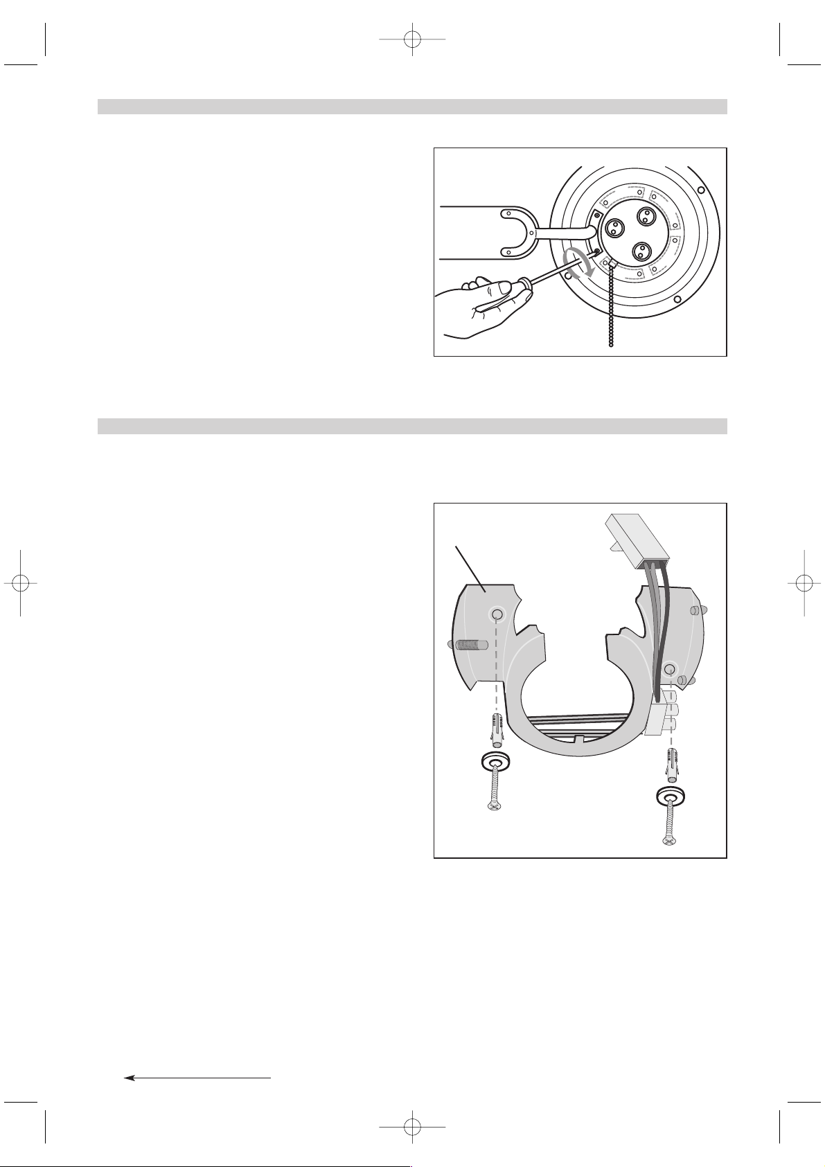
6.6 Hanging the Fan
DANGER: You must make certain that the electrical
connection wire is not under power.
1 Fasten the installation plate (L) to the ceiling with 2 screws
and, using the pegs if necessary.
WARNING: The room ceiling and the screw
connection must be capable of bearing a weight of at least
28 kg.
Use 8 x 50 mm screws with pegs.
For fastening to subceilings (e.g. Rigips), use special cavity
pegs. Alternatively, you can determine whether the installation
plate can be fastened to the lower structure of the subceiling
(squared beam, girder) which is capable of bearing more
weight, use wood screws.
Test the bearing capacity of the screw connection.
IB_KH1150_E2731_UK_V1.qxd 15.01.2007 14:47 Uhr Seite 10
L
Page 13
11
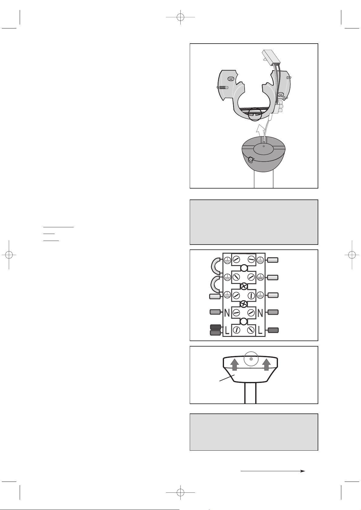
2 Hang the fan in the installation plate, making sure that the
mount lines up properly with the notch (see Fig.: circle).
3 Electrical connection
Colour coding:
Gr
een-yellow (I): PE conductor
Blue
(II): Neutral conductor
Br
own (III): Current-carrying wire (also: black)
Connect the electrical wires
Step 1: Connect the PE conductor to the lamp-wire
connector (I).
Step 2: Connect the blue wire (N) (II).
Step 3: Connect the brown wire (L) (III).
Connect the cable plug
Connect the cable plugs of the two PE conductors of the
fan with the sockets on the installation plate.
Then connect the wide cable plug of fan to the socket on
the installation plate.
4 Snap the casing (A) onto the installation plate: insert it into
the two adjacent bearings and snap it into the opposing
spring-loaded bearing (click!).
5 Insert the halogen bulbs into the lamp: place the bulbs
into the round grooves with light pressure, then turn
clockwise until tight.
6 Switch on the power supply.
DANGER: The electrical connection may only
be performed by a qualified electrician!
Failure to follow these instructions presents a lifethreatening risk of electric shock!!
“KLICK”
NOTE: Avoid touching the halogen bulbs with
your fingers. Use a clean cloth or cloth gloves when
inserting the bulbs
IB_KH1150_E2731_UK_V1.qxd 15.01.2007 14:47 Uhr Seite 11
1
(I)
(II)
2
(III)
3
A
Page 14
12
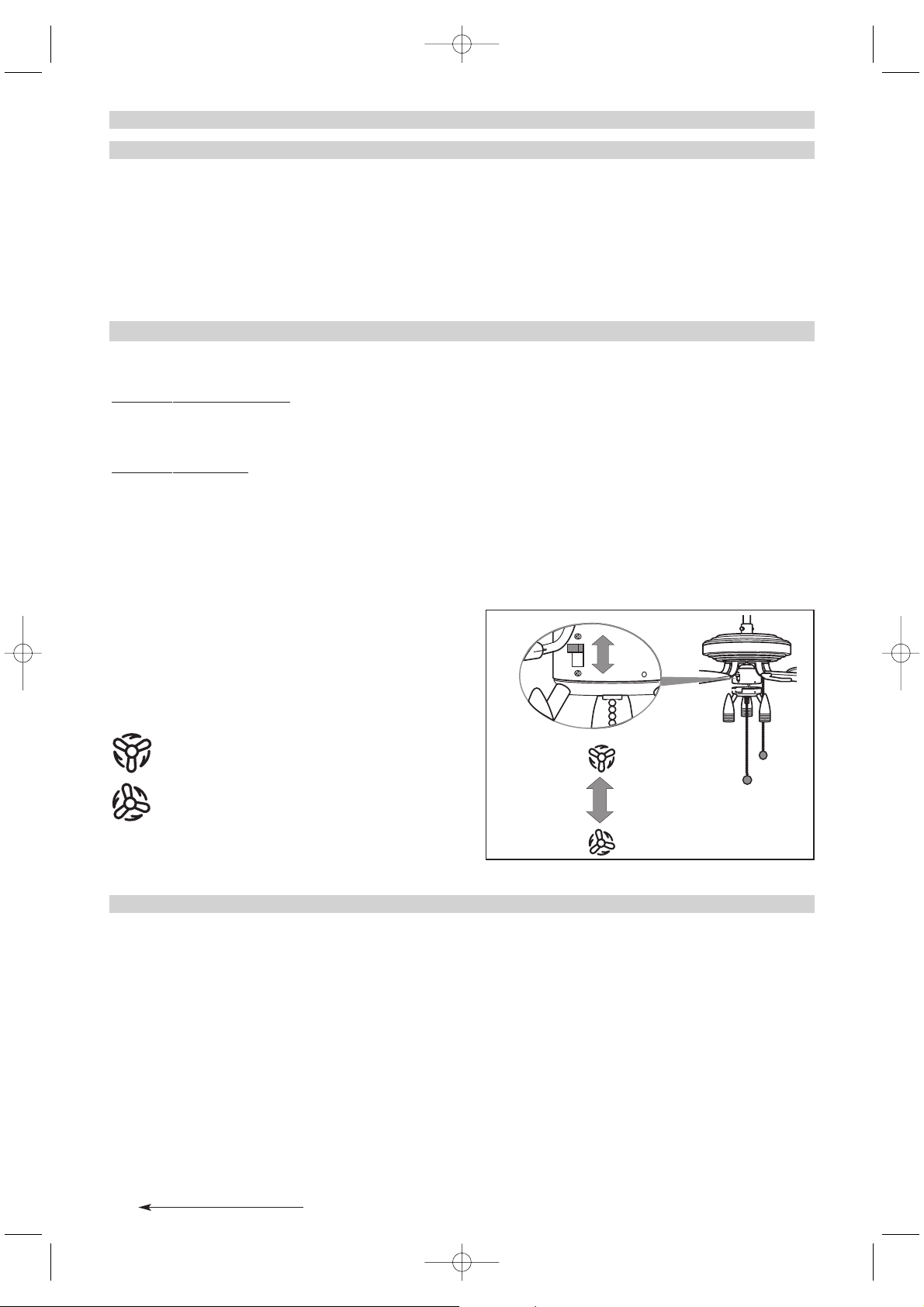
7 Operation
7.1 Setting the Speed
Set the speed level with the pull chain (G) on the motor
housing. Each pull changes the speed in the following
sequence:
Fast - medium - slow - OFF
Switch the light on with the middle pull chain (F).
If the fan is also switched on and off with a switch or a
circuit breaker, it will start at the last speed set, unless it
was switched off using the pull chain.
7.2 Setting the Direction
INFO: Direction
The fan tur
ns counterclockwise:
Classic fan function. The downward air flow creates a
cooling effect. Typically used during warm times of the year.
The fan tur
ns clockwise:
The air flow is directed toward the ceiling. The heated
room air is distributed better throughout the room and the
accumulation of warm air near the ceiling is prevented.
CAUTION: Only operate the direction switch while
the fan is stopped to prevent damage to the fan motor.
Change the direction with the sliding switch.
Switch positions:
Up: The fan turns clockwise.
Down: The fan turns counterclockwise.
(as viewed from below)
8 Cleaning
DANGER: Disconnect the fan from the mains
network before cleaning it: switch off the corresponding
building fuse or circuit breaker. Touching cables or
components under power presents a life-threatening risk!
Wipe the fan off with a soft cloth, which may be slightly
moistened for stubborn dirt. Do not use any solvents,
abrasive cleansers or sharp objects, e.g. rough sponges or
brushes, to avoid scratching the fan.
IB_KH1150_E2731_UK_V1.qxd 15.01.2007 14:47 Uhr Seite 12
Page 15

13
9 Troubleshooting
Do not perform any modifications or repairs on the product!
Safety-relevant parts may only be repaired by an expert.
Problem/Fault Possible Cause(s) Remedy
The fastening screws cannot be
screwed tightly or were turned too
far during installation
Replace the screws and nuts. Only
use screws that match the original
screws; contact the manufacturer or
retailer for information.
The fan does not start Building fuse or circuit breaker
defective
Check the building fuse or circuit
breaker and replace if necessary
The direction switch is positioned in
the middle
Set the direction switch to the up or
down position
Set the pull chain switch to the "OFF"
setting
Pull the pull chain once
Loose cable plug
DANGER: Disconnect the
fan from the mains network before
checking the cable plug.
Check the cable plug
Fan defective Have the fan inspected by an expert
or send it to customer service (See
the enclosed "Warranty" for the
service address)
Fan runs loadly or sways significantly Blade mounts not firmly connected Check the screw connection of the
blade mounts
Blade damaged Check the blades, replace if
necessary
Blades not balanced out Change the positioning of the blades
amongst themselves.
Loose blade attachment(s) Check the blade attachments
Fan is not hung correctly
DANGER: Disconnect the
fan from the mains network before
checking whether it is hung correctly.
Check the fastening of the
installation plate and extension rod,
and correct any improper fastening
Light does not function Bulb defective Check the halogen bulbs and
replace defective bulbs
Loose cable plug
DANGER: Disconnect the
fan from the mains network before
checking the cable plug. Check the
cable plug
IB_KH1150_E2731_UK_V1.qxd 15.01.2007 14:47 Uhr Seite 13
Page 16

14
10 Warranty and Service
The warranty conditions and the service address can be found in the enclosed document.
11 Technical data
Product: Ceiling Fan KH 1150
Mains voltage: 220 - 240 V~, 50 Hz
Rated output: Fan 60 W
Lights: 3 x max. 50 W GU10
Materials: Metal and MDF
Dimensions: 131 x 40 cm (35 cm with the shorter extension rod)
Weight (incl.): 6750 g
Labeled with testing certification: CE, GS
12 Importer
KOMPERNASS GMBH
BURGSTRASSE 21
D-44867 BOCHUM
www.kompernass.com
13 Disposal
Do not dispose of the device in normal domestic waste.
Dispose of the device over a registered waste disposal firm or through your communal waste disposal facility.
Observe the currently valid regulations. In case of doubt, consult your waste disposal facility.
Dispose of the packaging materials in an environmentally responsible manner.
IB_KH1150_E2731_UK_V1.qxd 15.01.2007 14:47 Uhr Seite 14
Page 17

15
IB_KH1150_E2731_UK_V1.qxd 15.01.2007 14:47 Uhr Seite 15
 Loading...