

KOMATSU WA500-6H-M book
Operation & Maintenance
Manual
VEAM430100
WA500-6H
WHEEL LOADER
SERIAL NUMBERS
WARNING
Unsafe use of this machine may cause serious injury or
death. Operators and maintenance personnel must read
this manual before operating or maintaining this
machine. This manual should be kept near the machine
for reference and periodically reviewed by all personnel
who will come into contact with it.
NOTICE
Komatsu has had the operating and maintenance instructions translated into all the languages of the member states in the European Union. Should you wish to
have a version of the operating instructions in another
language, please dont hesitate to ask at your local
dealers.
H60051
and up
© 2006 Komatsu Hanomag GmbH
All Rights Reserved
Printed in Europ 06-2006


Foreword
1. Foreword
WA500-6H – VEAM430100 1-1
1.1 Foreword Foreword
1.1 Foreword
This manual provides rules and guidelines which will help you
use this machine safely and effectively. The precautions in this
manual must be followed at all times when performing operation
and maintenance. Most accidents are caused by the failure to
follow fundamental safety rules for the operation and maintenance of machines. Accidents can be prevented by knowing
beforehand conditions that may cause a hazard when performing operation and maintenance.
WARNING
z
Operators and maintenance personnel must always do as
follows before beginning operation or maintenance.
z
Always be sure to read and understand this manual thoroughly before performing operation and maintenance.
z
Read the safety messages given in this manual and the
safety labels affixed to the machine thoroughly and be sure
that you understand them fully.
z
Keep this manual at the storage location for the Operation
and Maintenance Manual given below, and have all personnel read it periodically.
z
If this manual has been lost or has become dirty and cannot
be read, request a replacement manual immediately from
KOMATSU or your KOMATSU distributor.
z
If you sell the machine, be sure to give this manual to the
new owners together with the machine.
z
KOMATSU delivers machines that comply with all applicable
regulations and standards of the country to which it has
been shipped. If this machine has been purchased in
another country or purchased from someone in another
country, it may lack certain safety devices and specifications
that are necessary for use in your country. If there is any
question about whether your product complies with the
applicable standards and regulations of your country, consult
KOMATSU or your KOMATSU distributor before operating
the machine.
Storage location for the Operation and Maintenance Manual:
Pocket (1) at rear of operator’s seat
1
GK032001
1-2 WA500-6H – VEAM430100

Foreword 1.1 Foreword
1.1.1 EU Directives
Machines supplied by us fulfil the Directive for Machinery 89/
392/EEC and all supplements. If the machine is being used in
another country, it is possible that certain safety regulations and
specifications may not be fulfilled for use in that country. For
example, priority vehicle warning lamps may be used in some
countries, but are forbidden in others.
Please contact our dealer before using the machine if you have
any questions regarding the fulfilment of standards and regulations in a specific country.
Notes on subsequent installation of electrical and electronic equipment and components
Electrical and electronic equipment and/or components which
have been installed subsequently, emit electromagnetic radiation which can influence the function of the electronic components and sections of the machine. This can have an influence
on the safety of the machine and endanger persons. For this
reason, please ensure that the following safety instructions are
observed.
If you are installing electrical or electronic equipment and/or
components in the machine and connect them to the vehicle
electrical system, you must check at own responsibility that the
installations do not cause any disturbance to the vehicle’s electronic system or other components. Above all, you must ensure
that any subsequently installed electrical and electronic components comply with the EMV Directive 89/336/EEC in its current
edition and bear the CE mark.
The following requirements also have to be met for subsequent
installation of mobile communication systems (e.g. radio, telephone):
z
Only equipment approved by national legislation (e.g. BZT
approval for Germany) may be used
z
The unit must be fixed in position
z
Portable or mobile units may only be used inside the vehicles if they are connected to a fixed outside antenna
z
The transmitter unit must be spatially separated from the
vehicle’s electronic system
z
Make sure when installing the antenna that this is installed
correctly with good earth connection between antenna and
vehicle mass
Also observe KOMATSU and manufacturer’s installation instructions for wiring, installation and maximum permitted power consumption.
WA500-6H – VEAM430100 1-3
1.2 Safety information Foreword
1.2 Safety information
To enable you to use this machine safely, safety precautions and
labels are given in this manual and affixed to the machine to give
explanations of situations involving potential hazards and of the
methods of avoiding such situations.
1.2.1 Signal words
The following signal words are used to inform you that there is a
potential hazardous situation that may lead to personal injury or
damage.
In this manual and on machine labels, the following signal words
are used to express the potential level of hazard.
DANGER
Indicates an imminently hazardous situation which, if not
avoided, will result in death or serious injury.
WARNING
Indicates a potentially hazardous situation which, if not avoided,
could result in death or serious injury.
CAUTION
Indicates a potentially hazardous situation which, if not avoided,
may result in minor or moderate injury. This word is used also to
alert against unsafe practices that may cause property damage.
Example of safety message using signal word
WARNING
When standing up from the operator’s seat, always place the
work equipment lock lever in the LOCK position.
If you accidentally touch the control levers when they are not
locked, this may cause a serious injury or death.
1-4 WA500-6H – VEAM430100
Foreword 1.2 Safety information
Other signal words
In addition to the above, the following signal words are used to
indicate precautions that should be followed to protect the
machine or to give information that is useful to know.
NOTE
This word is used for precautions that must be taken to avoid
actions which could shorten the life of the machine.
REMARK
This word is used for information that is useful to know.
1.2.2 Safety labels
Safety labels are affixed to the machine to inform the operator or
maintenance worker on the spot when carrying out operation or
maintenance of the machine that may involve hazard.
For details of safety labels, see "Safety labels (2-2)".
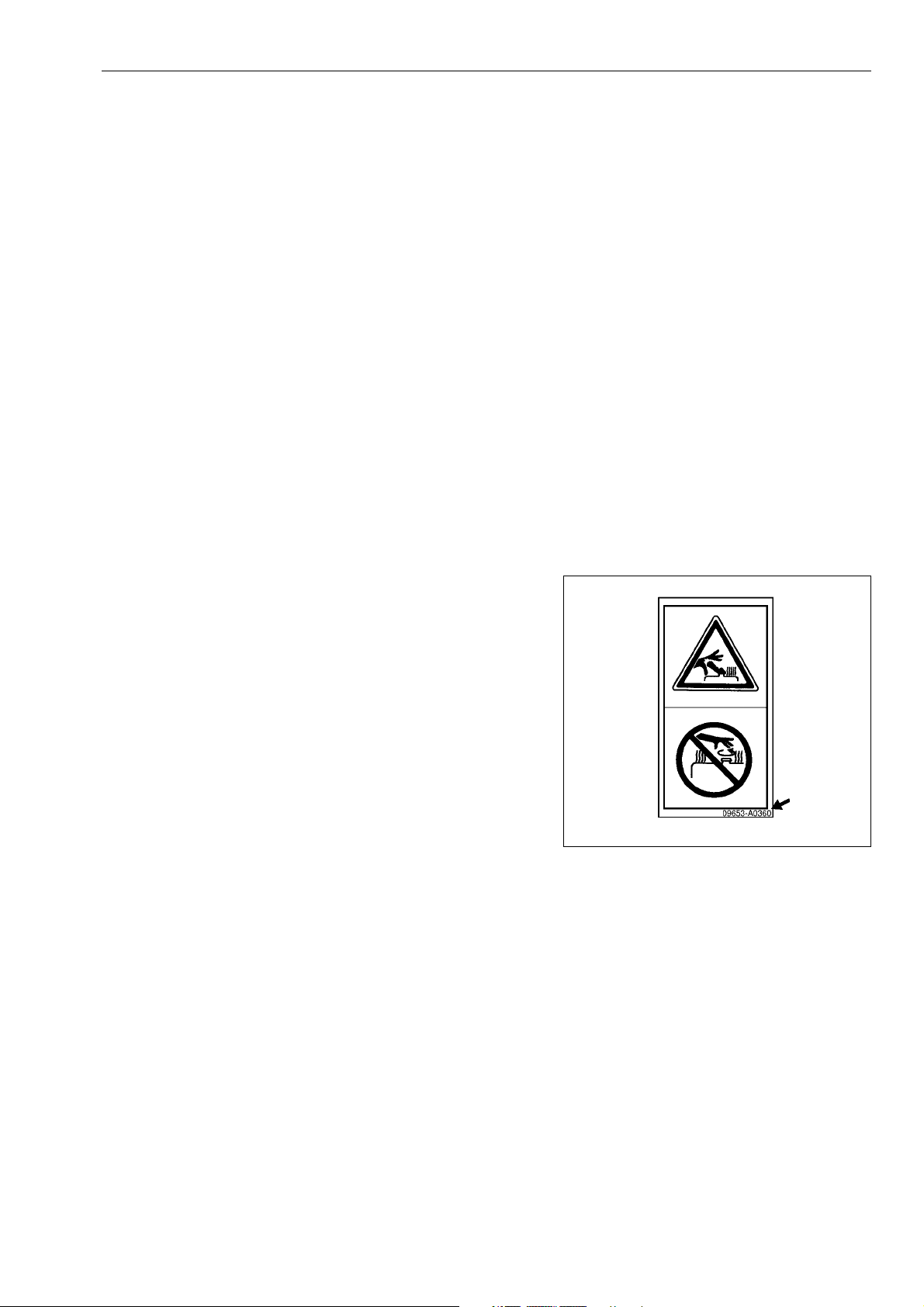
Safety labels using pictogram
Safety pictograms use a picture to express a level of hazardous
condition equivalent to the signal word. These safety pictograms
use pictures in order to let the operator or maintenance worker
understand the level and type of hazardous condition at all
times. Safety pictograms show the type of hazardous condition
at the top or left side, and the method of avoiding the hazardous
condition at the bottom or right side. In addition, the type of hazardous condition is displayed inside a triangle and the method of
avoiding the hazardous condition is shown inside a circle.
KOMATSU cannot predict every circumstance that might involve
a potential hazard in operation and maintenance. Therefore, the
safety messages in this manual and on the machine may not
include all possible safety precautions.
If any procedures or actions not specifically recommended or
allowed in this manual are used, it is your responsibility to take
the necessary steps to ensure safety.
In no event should you engage in prohibited uses or actions
described in this manual.
The explanations, values, and illustrations in this manual were
prepared based on the latest information available at that time.
Continuing improvements in the design of this machine can
lead to changes in detail which may not be reflected in this manual. Consult KOMATSU or your KOMATSU distributor for the
latest available information of your machine or for questions
regarding information in this manual.
Part No
GK032002
WA500-6H – VEAM430100 1-5

1.3 Introduction Foreword
1.3 Introduction
This loader is a machine with independent transmission, moving
on chains or wheels. Driving in forward direction, the loader can
load or dig material using its attachments intended for loading
operations (i.e. bucket).
This KOMATSU machine is designed to be used mainly for the
following work:
z
Digging work
z
Smoothing
z
Pushing work
z
Loading work
For details of the operating procedure, see "Work possible using
wheel loader (3-128)".
1.3.1 Intended use
If you use the machine for any other purpose than specified
above, we will not accept any responsibility for safety. All considerations concerning safety will then be up to the owner or the
operating and maintenance personnel. In any case, neither you
nor any other person are/is authorised to perform work and functions explicitly prohibited in these operating instructions.
The transport of persons in the work equipment is strictly
forbidden!
For details of the operating procedure, see "Work possible using
wheel loader (3-128)".
1-6 WA500-6H – VEAM430100
Foreword 1.3 Introduction
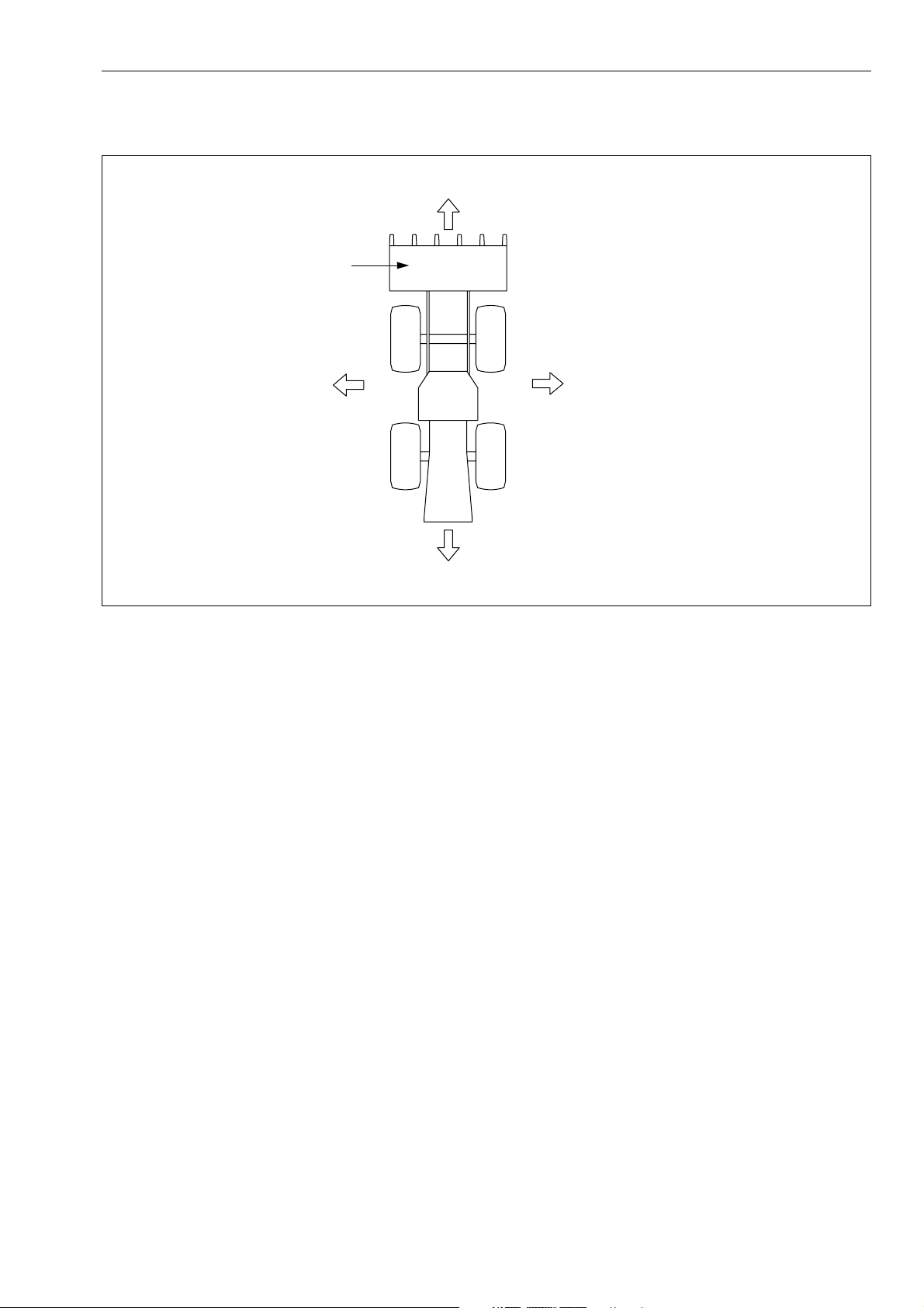
1.3.2 Directions of machine
Front
Bucket
Left
Rear
In this manual, the directions of the machine (front, rear, left,
right) are determined according to the view from the operator’s
seat in the direction of travel (front) of the machine.
Right
GK032003
WA500-6H – VEAM430100 1-7
1.3 Introduction Foreword
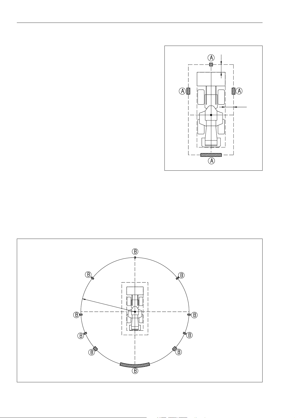
1.3.3 Visibility from operator’s seat
The visibility standards (ISO 5006) for this machine require a
view shown in the diagram on the right side.
1 m
Visibility in immediate area
The visibility of this machine in the area 1 m from the outside
surface of the machine at a height of 1.5 m is shown in the diagram on the right side. The hatched area (A) shows the area
where the view is blocked by part of the machine when mirrors
or other aids to visibility are installed as standard. Please be fully
aware that there are places that cannot be seen when operating
the machine.
1 m
12-M Radius visibility
The visibility at a radius of 12 m from the machine is as shown in
the diagram below. The hatched areas (B) show the areas
where the view is blocked when mirrors or other aids to visibility
are installed as standard. Please be fully aware that there are
places that cannot be seen when operating the machine.
1
2
m
GK050001
GK050002
1-8 WA500-6H – VEAM430100
Foreword 1.4 Necessary information
1.4 Necessary information
When requesting service or ordering replacement parts, please
inform your KOMATSU distributor of the following items.
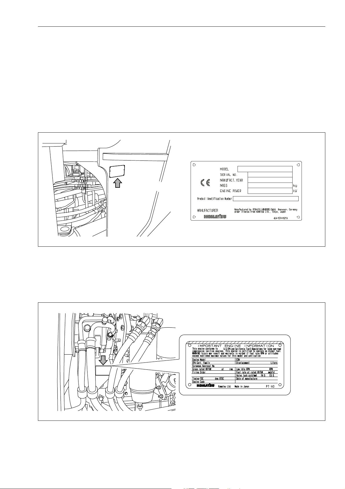
1.4.1 Product Identification Number (PIN)/Machine serial no. plate and position
On the center right of the front frame.
1.4.2 Engine serial no. plate and position
It is on the air conditioner compressor bracket on the right side
of the machine.
GK050003GB
GK050004
EPA: Environmental Protection Agency, U.S.A.
WA500-6H – VEAM430100 1-9
1.4 Necessary information Foreword
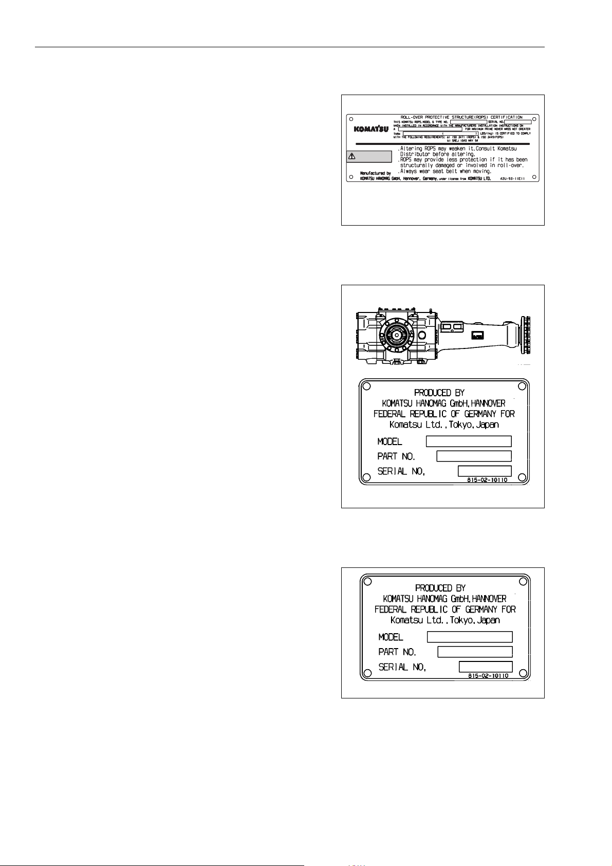
1.4.3 ROPS/FOPS-Cab serial no. plate
This plate is located on the right inside cab on the rear beam.
WARNING
GK032006
1.4.4 Axle serial no. plate
This plate is located on the right of front axle and on the left of
rear axle.
1.4.5 Transmission serial no. plate
This plate is located in travel direction front, above the
transmission output.
GK032007
GK032008
1-10 WA500-6H – VEAM430100
Foreword 1.4 Necessary information
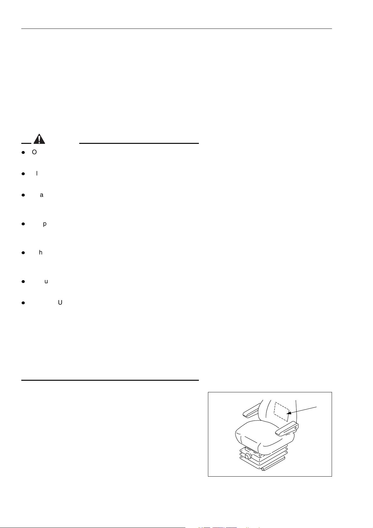
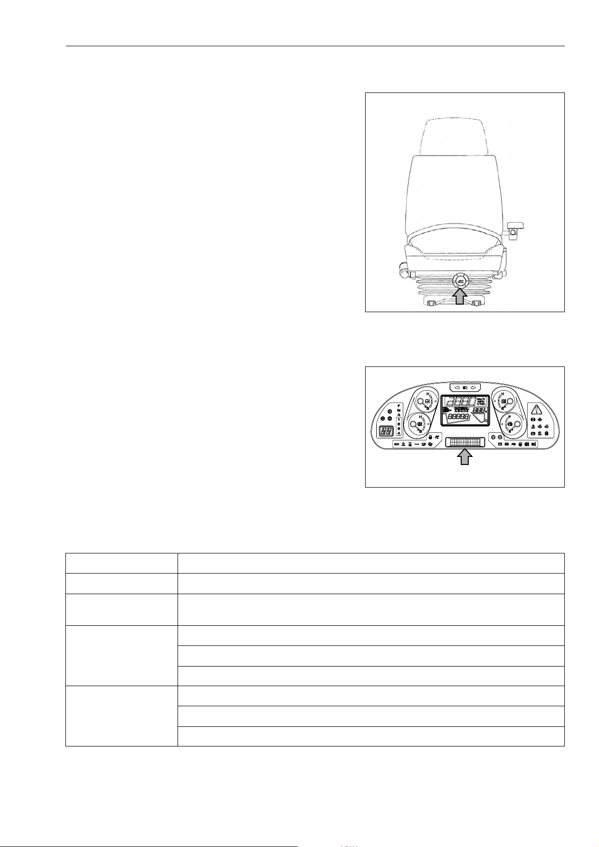
1.4.6 Seat operator serial no. plate
This plate is located in front of seat, covered by the bellows.
GK032009
1.4.7 Position of service meter
The service meter is displayed on the character display at the
bottom center of the machine monitor.
1.4.8 Table to enter serial no. and distributor
Machine serial No.
Engine serial No.
Product identification
number (PIN)
GK050027
Distributor name
Address
Service Personnel
Phone/Fax
WA500-6H – VEAM430100 1-11

1.5 Contents Foreword
1.5 Contents
1. Foreword. . . . . . . . . . . . . . . . . . . . . . . . . . . . . . . . . . . . . . . . . . . . . . . . . . . . . . 1-1
1.1 Foreword . . . . . . . . . . . . . . . . . . . . . . . . . . . . . . . . . . . . . . . . . . . . . . . . . . . . . . . . . . . . . . . . . . . . 1-2
1.1.1 EU Directives. . . . . . . . . . . . . . . . . . . . . . . . . . . . . . . . . . . . . . . . . . . . . . . . . . . . . . . . . . 1-3
1.2 Safety information . . . . . . . . . . . . . . . . . . . . . . . . . . . . . . . . . . . . . . . . . . . . . . . . . . . . . . . . . . . . 1-4
1.2.1 Signal words . . . . . . . . . . . . . . . . . . . . . . . . . . . . . . . . . . . . . . . . . . . . . . . . . . . . . . . . . 1-4
1.2.2 Safety labels. . . . . . . . . . . . . . . . . . . . . . . . . . . . . . . . . . . . . . . . . . . . . . . . . . . . . . . . . .1-5
1.3 Introduction. . . . . . . . . . . . . . . . . . . . . . . . . . . . . . . . . . . . . . . . . . . . . . . . . . . . . . . . . . . . . . . . . . 1-6
1.3.1 Intended use . . . . . . . . . . . . . . . . . . . . . . . . . . . . . . . . . . . . . . . . . . . . . . . . . . . . . . . . . . 1-6
1.3.2 Directions of machine . . . . . . . . . . . . . . . . . . . . . . . . . . . . . . . . . . . . . . . . . . . . . . . . . . .1-7
1.3.3 Visibility from operator’s seat. . . . . . . . . . . . . . . . . . . . . . . . . . . . . . . . . . . . . . . . . . . . . . 1-8
1.4 Necessary information . . . . . . . . . . . . . . . . . . . . . . . . . . . . . . . . . . . . . . . . . . . . . . . . . . . . . . . . . 1-9
1.4.1 Product Identification Number (PIN)/Machine serial no. plate and position . . . . . . . . . . 1-9
1.4.2 Engine serial no. plate and position. . . . . . . . . . . . . . . . . . . . . . . . . . . . . . . . . . . . . . . . . 1-9
1.4.3 ROPS/FOPS-Cab serial no. plate . . . . . . . . . . . . . . . . . . . . . . . . . . . . . . . . . . . . . . . . . 1-10
1.4.4 Axle serial no. plate . . . . . . . . . . . . . . . . . . . . . . . . . . . . . . . . . . . . . . . . . . . . . . . . . . . .1-10
1.4.5 Transmission serial no. plate. . . . . . . . . . . . . . . . . . . . . . . . . . . . . . . . . . . . . . . . . . . . . 1-10
1.4.6 Seat operator serial no. plate . . . . . . . . . . . . . . . . . . . . . . . . . . . . . . . . . . . . . . . . . . . . 1-11
1.4.7 Position of service meter . . . . . . . . . . . . . . . . . . . . . . . . . . . . . . . . . . . . . . . . . . . . . . . . 1-11
1.4.8 Table to enter serial no. and distributor . . . . . . . . . . . . . . . . . . . . . . . . . . . . . . . . . . . . . 1-11
1.5 Contents . . . . . . . . . . . . . . . . . . . . . . . . . . . . . . . . . . . . . . . . . . . . . . . . . . . . . . . . . . . . . . . . . . . 1-12
1.6 Dimensions, weights and operating data. . . . . . . . . . . . . . . . . . . . . . . . . . . . . . . . . . . . . . . . . 1-19
1.6.1 WA500-6: Dimensions, weights and operating data . . . . . . . . . . . . . . . . . . . . . . . . . . . 1-19
1.7 CE-Conforming equipment . . . . . . . . . . . . . . . . . . . . . . . . . . . . . . . . . . . . . . . . . . . . . . . . . . . . 1-20
1.7.1 CE-Conforming equipment . . . . . . . . . . . . . . . . . . . . . . . . . . . . . . . . . . . . . . . . . . . . . . 1-20
1.7.2 Manufacturer-supplied CE-Conforming equipment, according to document
419-93-H1250 . . . . . . . . . . . . . . . . . . . . . . . . . . . . . . . . . . . . . . . . . . . . . . . . . . . . . . . . 1-21
2. Safety . . . . . . . . . . . . . . . . . . . . . . . . . . . . . . . . . . . . . . . . . . . . . . . . . . . . . . . . 2-1
2.1 Safety labels . . . . . . . . . . . . . . . . . . . . . . . . . . . . . . . . . . . . . . . . . . . . . . . . . . . . . . . . . . . . . . . . . 2-2
2.1.1 Location of safety labels . . . . . . . . . . . . . . . . . . . . . . . . . . . . . . . . . . . . . . . . . . . . . . . . .2-2
2.1.2 Presentation of safety labels . . . . . . . . . . . . . . . . . . . . . . . . . . . . . . . . . . . . . . . . . . . . . . 2-3
2.2 General precautions . . . . . . . . . . . . . . . . . . . . . . . . . . . . . . . . . . . . . . . . . . . . . . . . . . . . . . . . . . . 2-6
2.3 Precautions for operation . . . . . . . . . . . . . . . . . . . . . . . . . . . . . . . . . . . . . . . . . . . . . . . . . . . . . 2-17
2.3.1 Starting engine . . . . . . . . . . . . . . . . . . . . . . . . . . . . . . . . . . . . . . . . . . . . . . . . . . . . . . . 2-17
2.3.2 Operation. . . . . . . . . . . . . . . . . . . . . . . . . . . . . . . . . . . . . . . . . . . . . . . . . . . . . . . . . . . . 2-19
2.3.3 Transportation . . . . . . . . . . . . . . . . . . . . . . . . . . . . . . . . . . . . . . . . . . . . . . . . . . . . . . . . 2-26
2.3.4 Battery . . . . . . . . . . . . . . . . . . . . . . . . . . . . . . . . . . . . . . . . . . . . . . . . . . . . . . . . . . . . . . 2-28
2.3.5 Towing . . . . . . . . . . . . . . . . . . . . . . . . . . . . . . . . . . . . . . . . . . . . . . . . . . . . . . . . . . . . . . 2-30
2.4 Precautions for maintenance . . . . . . . . . . . . . . . . . . . . . . . . . . . . . . . . . . . . . . . . . . . . . . . . . . 2-31
2.5 Precautions with tires . . . . . . . . . . . . . . . . . . . . . . . . . . . . . . . . . . . . . . . . . . . . . . . . . . . . . . . . 2-40
1-12 WA500-6H – VEAM430100

Foreword 1.5 Contents
3. Operation . . . . . . . . . . . . . . . . . . . . . . . . . . . . . . . . . . . . . . . . . . . . . . . . . . . . . 3-1
3.1 General view . . . . . . . . . . . . . . . . . . . . . . . . . . . . . . . . . . . . . . . . . . . . . . . . . . . . . . . . . . . . . . . . 3-2
3.1.1 General view of machine . . . . . . . . . . . . . . . . . . . . . . . . . . . . . . . . . . . . . . . . . . . . . . . . 3-2
3.1.2 General view of controls and gauges . . . . . . . . . . . . . . . . . . . . . . . . . . . . . . . . . . . . . . . 3-3
3.2 Explanation of components . . . . . . . . . . . . . . . . . . . . . . . . . . . . . . . . . . . . . . . . . . . . . . . . . . . . 3-8
3.2.1 Machine monitor . . . . . . . . . . . . . . . . . . . . . . . . . . . . . . . . . . . . . . . . . . . . . . . . . . . . . . . 3-8
Types of warning . . . . . . . . . . . . . . . . . . . . . . . . . . . . . . . . . . . . . . . . . . . . . . . . . . . . . . 3-9
Central warning lamp . . . . . . . . . . . . . . . . . . . . . . . . . . . . . . . . . . . . . . . . . . . . . . . . . . 3-10
Character display portion . . . . . . . . . . . . . . . . . . . . . . . . . . . . . . . . . . . . . . . . . . . . . . . 3-11
Emergency stop item . . . . . . . . . . . . . . . . . . . . . . . . . . . . . . . . . . . . . . . . . . . . . . . . . . 3-17
Caution items . . . . . . . . . . . . . . . . . . . . . . . . . . . . . . . . . . . . . . . . . . . . . . . . . . . . . . . . 3-20
Inspection and maintenance item. . . . . . . . . . . . . . . . . . . . . . . . . . . . . . . . . . . . . . . . . 3-24
Pilot display portion . . . . . . . . . . . . . . . . . . . . . . . . . . . . . . . . . . . . . . . . . . . . . . . . . . . 3-28
Meter display portion . . . . . . . . . . . . . . . . . . . . . . . . . . . . . . . . . . . . . . . . . . . . . . . . . . 3-34
Other functions of machine monitor . . . . . . . . . . . . . . . . . . . . . . . . . . . . . . . . . . . . . . . 3-37
3.2.2 Switches . . . . . . . . . . . . . . . . . . . . . . . . . . . . . . . . . . . . . . . . . . . . . . . . . . . . . . . . . . . . 3-46
3.2.3 Control levers, pedals. . . . . . . . . . . . . . . . . . . . . . . . . . . . . . . . . . . . . . . . . . . . . . . . . . 3-67
3.2.4 Steering tilt lock lever . . . . . . . . . . . . . . . . . . . . . . . . . . . . . . . . . . . . . . . . . . . . . . . . . . 3-74
3.2.5 Cap with lock . . . . . . . . . . . . . . . . . . . . . . . . . . . . . . . . . . . . . . . . . . . . . . . . . . . . . . . . 3-75
3.2.6 Safety bar . . . . . . . . . . . . . . . . . . . . . . . . . . . . . . . . . . . . . . . . . . . . . . . . . . . . . . . . . . . 3-76
3.2.7 Towing pin . . . . . . . . . . . . . . . . . . . . . . . . . . . . . . . . . . . . . . . . . . . . . . . . . . . . . . . . . . 3-77
3.2.8 Backup alarm . . . . . . . . . . . . . . . . . . . . . . . . . . . . . . . . . . . . . . . . . . . . . . . . . . . . . . . . 3-77
3.2.9 Opening cab, window door. . . . . . . . . . . . . . . . . . . . . . . . . . . . . . . . . . . . . . . . . . . . . . 3-78
Open lock cancel knob for right cab door. . . . . . . . . . . . . . . . . . . . . . . . . . . . . . . . . . . 3-78
Cab left door open lock . . . . . . . . . . . . . . . . . . . . . . . . . . . . . . . . . . . . . . . . . . . . . . . . 3-79
Cab left door open knob. . . . . . . . . . . . . . . . . . . . . . . . . . . . . . . . . . . . . . . . . . . . . . . . 3-79
Open lock cancel knob for left cab window . . . . . . . . . . . . . . . . . . . . . . . . . . . . . . . . . 3-80
3.2.10 Handling cab wiper . . . . . . . . . . . . . . . . . . . . . . . . . . . . . . . . . . . . . . . . . . . . . . . . . . . . 3-80
Preventing damage to wiper arm bracket. . . . . . . . . . . . . . . . . . . . . . . . . . . . . . . . . . . 3-80
3.2.11 Dust indicator . . . . . . . . . . . . . . . . . . . . . . . . . . . . . . . . . . . . . . . . . . . . . . . . . . . . . . . . 3-81
3.2.12 Fuse . . . . . . . . . . . . . . . . . . . . . . . . . . . . . . . . . . . . . . . . . . . . . . . . . . . . . . . . . . . . . . . 3-81
Fuse capacity and name of circuit . . . . . . . . . . . . . . . . . . . . . . . . . . . . . . . . . . . . . . . . 3-82
3.2.13 Slow blow fuse . . . . . . . . . . . . . . . . . . . . . . . . . . . . . . . . . . . . . . . . . . . . . . . . . . . . . . . 3-83
3.2.14 Power outlet . . . . . . . . . . . . . . . . . . . . . . . . . . . . . . . . . . . . . . . . . . . . . . . . . . . . . . . . . 3-83
3.2.15 Air conditioner . . . . . . . . . . . . . . . . . . . . . . . . . . . . . . . . . . . . . . . . . . . . . . . . . . . . . . . 3-84
General locations and function of control panel . . . . . . . . . . . . . . . . . . . . . . . . . . . . . . 3-84
Method of operation . . . . . . . . . . . . . . . . . . . . . . . . . . . . . . . . . . . . . . . . . . . . . . . . . . . 3-86
Cool box . . . . . . . . . . . . . . . . . . . . . . . . . . . . . . . . . . . . . . . . . . . . . . . . . . . . . . . . . . . . 3-88
Precautions when using . . . . . . . . . . . . . . . . . . . . . . . . . . . . . . . . . . . . . . . . . . . . . . . . 3-88
Inspection and maintenance . . . . . . . . . . . . . . . . . . . . . . . . . . . . . . . . . . . . . . . . . . . . 3-89
3.3 Operation . . . . . . . . . . . . . . . . . . . . . . . . . . . . . . . . . . . . . . . . . . . . . . . . . . . . . . . . . . . . . . . . . . 3-90
3.3.1 Check before starting engine, adjust . . . . . . . . . . . . . . . . . . . . . . . . . . . . . . . . . . . . . . 3-90
Walk-around check. . . . . . . . . . . . . . . . . . . . . . . . . . . . . . . . . . . . . . . . . . . . . . . . . . . . 3-90
Check before starting . . . . . . . . . . . . . . . . . . . . . . . . . . . . . . . . . . . . . . . . . . . . . . . . . . 3-94
Adjustment . . . . . . . . . . . . . . . . . . . . . . . . . . . . . . . . . . . . . . . . . . . . . . . . . . . . . . . . . 3-103
Safety belt . . . . . . . . . . . . . . . . . . . . . . . . . . . . . . . . . . . . . . . . . . . . . . . . . . . . . . . . . 3-104
Operations and checks before starting engine. . . . . . . . . . . . . . . . . . . . . . . . . . . . . . 3-106
WA500-6H – VEAM430100 1-13

1.5 Contents Foreword
3.3.2 Starting engine . . . . . . . . . . . . . . . . . . . . . . . . . . . . . . . . . . . . . . . . . . . . . . . . . . . . . .3-108
Automatic warming-up operation. . . . . . . . . . . . . . . . . . . . . . . . . . . . . . . . . . . . . . . . . 3-109
3.3.3 Operations and checks after starting engine . . . . . . . . . . . . . . . . . . . . . . . . . . . . . . . . 3-110
Breaking-in the machine . . . . . . . . . . . . . . . . . . . . . . . . . . . . . . . . . . . . . . . . . . . . . . . 3-110
Normal operation . . . . . . . . . . . . . . . . . . . . . . . . . . . . . . . . . . . . . . . . . . . . . . . . . . . . . 3-111
3.3.4 Stopping engine. . . . . . . . . . . . . . . . . . . . . . . . . . . . . . . . . . . . . . . . . . . . . . . . . . . . . . 3-112
3.3.5 Check after stopping engine . . . . . . . . . . . . . . . . . . . . . . . . . . . . . . . . . . . . . . . . . . . . 3-112
3.3.6 Moving the machine (directional, speed), stopping the machine. . . . . . . . . . . . . . . . . 3-113
Preparations for moving the machine . . . . . . . . . . . . . . . . . . . . . . . . . . . . . . . . . . . . . 3-113
Changing gear speed . . . . . . . . . . . . . . . . . . . . . . . . . . . . . . . . . . . . . . . . . . . . . . . . . 3-116
Changing direction. . . . . . . . . . . . . . . . . . . . . . . . . . . . . . . . . . . . . . . . . . . . . . . . . . . . 3-117
Automatic shift . . . . . . . . . . . . . . . . . . . . . . . . . . . . . . . . . . . . . . . . . . . . . . . . . . . . . . . 3-118
Stopping the machine . . . . . . . . . . . . . . . . . . . . . . . . . . . . . . . . . . . . . . . . . . . . . . . . . 3-119
Transmission cut-off function. . . . . . . . . . . . . . . . . . . . . . . . . . . . . . . . . . . . . . . . . . . . 3-120
3.3.7 Turning . . . . . . . . . . . . . . . . . . . . . . . . . . . . . . . . . . . . . . . . . . . . . . . . . . . . . . . . . . . . 3-122
3.3.8 Operation of work equipment . . . . . . . . . . . . . . . . . . . . . . . . . . . . . . . . . . . . . . . . . . . 3-123
Lift arm operation. . . . . . . . . . . . . . . . . . . . . . . . . . . . . . . . . . . . . . . . . . . . . . . . . . . . . 3-124
Bucket operation . . . . . . . . . . . . . . . . . . . . . . . . . . . . . . . . . . . . . . . . . . . . . . . . . . . . . 3-124
3.3.9 Semi auto digging operations . . . . . . . . . . . . . . . . . . . . . . . . . . . . . . . . . . . . . . . . . . . 3-125
3.3.10 Remote positioner . . . . . . . . . . . . . . . . . . . . . . . . . . . . . . . . . . . . . . . . . . . . . . . . . . . . 3-126
Operating remote bucket positioner . . . . . . . . . . . . . . . . . . . . . . . . . . . . . . . . . . . . . . 3-126
Operating remote boom positioner . . . . . . . . . . . . . . . . . . . . . . . . . . . . . . . . . . . . . . . 3-126
3.3.11 Work possible using wheel loader . . . . . . . . . . . . . . . . . . . . . . . . . . . . . . . . . . . . . . . . 3-128
Recommended combination of switches for operation . . . . . . . . . . . . . . . . . . . . . . . . 3-128
Digging operations. . . . . . . . . . . . . . . . . . . . . . . . . . . . . . . . . . . . . . . . . . . . . . . . . . . . 3-129
Leveling operation . . . . . . . . . . . . . . . . . . . . . . . . . . . . . . . . . . . . . . . . . . . . . . . . . . . . 3-132
Pushing operation . . . . . . . . . . . . . . . . . . . . . . . . . . . . . . . . . . . . . . . . . . . . . . . . . . . . 3-132
Load and carry operations. . . . . . . . . . . . . . . . . . . . . . . . . . . . . . . . . . . . . . . . . . . . . . 3-133
Loading operations . . . . . . . . . . . . . . . . . . . . . . . . . . . . . . . . . . . . . . . . . . . . . . . . . . . 3-133
Precautions when handling blasted rock . . . . . . . . . . . . . . . . . . . . . . . . . . . . . . . . . . . 3-135
3.3.12 Precautions for operation . . . . . . . . . . . . . . . . . . . . . . . . . . . . . . . . . . . . . . . . . . . . . . 3-147
Permissible water depth . . . . . . . . . . . . . . . . . . . . . . . . . . . . . . . . . . . . . . . . . . . . . . . 3-147
If wheel brake does not work. . . . . . . . . . . . . . . . . . . . . . . . . . . . . . . . . . . . . . . . . . . . 3-147
Precautions when driving up or down slopes . . . . . . . . . . . . . . . . . . . . . . . . . . . . . . . 3-147
3.3.13 Removal and installation of the bucket . . . . . . . . . . . . . . . . . . . . . . . . . . . . . . . . . . . . 3-150
Removing the bucket . . . . . . . . . . . . . . . . . . . . . . . . . . . . . . . . . . . . . . . . . . . . . . . . . . 3-150
Installing the bucket . . . . . . . . . . . . . . . . . . . . . . . . . . . . . . . . . . . . . . . . . . . . . . . . . . . 3-151
3.3.14 Parking machine . . . . . . . . . . . . . . . . . . . . . . . . . . . . . . . . . . . . . . . . . . . . . . . . . . . . . 3-154
3.3.15 Checks after completion of operation . . . . . . . . . . . . . . . . . . . . . . . . . . . . . . . . . . . . . 3-155
3.3.16 Locking . . . . . . . . . . . . . . . . . . . . . . . . . . . . . . . . . . . . . . . . . . . . . . . . . . . . . . . . . . . . 3-156
3.3.17 Handling the tires. . . . . . . . . . . . . . . . . . . . . . . . . . . . . . . . . . . . . . . . . . . . . . . . . . . . .3-157
Precautions when handling tires . . . . . . . . . . . . . . . . . . . . . . . . . . . . . . . . . . . . . . . . . 3-157
Tire pressure . . . . . . . . . . . . . . . . . . . . . . . . . . . . . . . . . . . . . . . . . . . . . . . . . . . . . . . . 3-157
Precautions for using load and carry method . . . . . . . . . . . . . . . . . . . . . . . . . . . . . . . 3-158
3.4 Transportation . . . . . . . . . . . . . . . . . . . . . . . . . . . . . . . . . . . . . . . . . . . . . . . . . . . . . . . . . . . . . 3-159
3.4.1 Transportation procedure . . . . . . . . . . . . . . . . . . . . . . . . . . . . . . . . . . . . . . . . . . . . . . 3-159
3.4.2 Loading, unloading work with trailers . . . . . . . . . . . . . . . . . . . . . . . . . . . . . . . . . . . . . 3-159
Loading . . . . . . . . . . . . . . . . . . . . . . . . . . . . . . . . . . . . . . . . . . . . . . . . . . . . . . . . . . . . 3-160
Securing machine . . . . . . . . . . . . . . . . . . . . . . . . . . . . . . . . . . . . . . . . . . . . . . . . . . . . 3-160
Unloading . . . . . . . . . . . . . . . . . . . . . . . . . . . . . . . . . . . . . . . . . . . . . . . . . . . . . . . . . . 3-162
1-14 WA500-6H – VEAM430100

Foreword 1.5 Contents
3.4.3 Lifting machine . . . . . . . . . . . . . . . . . . . . . . . . . . . . . . . . . . . . . . . . . . . . . . . . . . . . . . 3-163
Location of lifting position mark . . . . . . . . . . . . . . . . . . . . . . . . . . . . . . . . . . . . . . . . . 3-164
Lifting procedure. . . . . . . . . . . . . . . . . . . . . . . . . . . . . . . . . . . . . . . . . . . . . . . . . . . . . 3-165
3.5 Cold weather operation. . . . . . . . . . . . . . . . . . . . . . . . . . . . . . . . . . . . . . . . . . . . . . . . . . . . . . 3-166
3.5.1 Precautions for low temperature . . . . . . . . . . . . . . . . . . . . . . . . . . . . . . . . . . . . . . . . 3-166
Fuel and lubricants . . . . . . . . . . . . . . . . . . . . . . . . . . . . . . . . . . . . . . . . . . . . . . . . . . . 3-166
Coolant . . . . . . . . . . . . . . . . . . . . . . . . . . . . . . . . . . . . . . . . . . . . . . . . . . . . . . . . . . . . 3-166
Battery . . . . . . . . . . . . . . . . . . . . . . . . . . . . . . . . . . . . . . . . . . . . . . . . . . . . . . . . . . . . 3-167
3.5.2 Precautions after completion of work . . . . . . . . . . . . . . . . . . . . . . . . . . . . . . . . . . . . . 3-168
3.5.3 After cold weather . . . . . . . . . . . . . . . . . . . . . . . . . . . . . . . . . . . . . . . . . . . . . . . . . . . 3-168
3.5.4 Warming-up operation for steering hydraulic circuit in cold weather . . . . . . . . . . . . . 3-169
3.6 Long-term storage. . . . . . . . . . . . . . . . . . . . . . . . . . . . . . . . . . . . . . . . . . . . . . . . . . . . . . . . . . 3-170
3.6.1 Before storage . . . . . . . . . . . . . . . . . . . . . . . . . . . . . . . . . . . . . . . . . . . . . . . . . . . . . . 3-170
3.6.2 During storage . . . . . . . . . . . . . . . . . . . . . . . . . . . . . . . . . . . . . . . . . . . . . . . . . . . . . . 3-170
3.6.3 After storage. . . . . . . . . . . . . . . . . . . . . . . . . . . . . . . . . . . . . . . . . . . . . . . . . . . . . . . . 3-171
3.7 Troubleshooting . . . . . . . . . . . . . . . . . . . . . . . . . . . . . . . . . . . . . . . . . . . . . . . . . . . . . . . . . . . 3-172
3.7.1 When machine runs out of fuel. . . . . . . . . . . . . . . . . . . . . . . . . . . . . . . . . . . . . . . . . . 3-172
3.7.2 Towing the machine . . . . . . . . . . . . . . . . . . . . . . . . . . . . . . . . . . . . . . . . . . . . . . . . . . 3-174
When engine can be used . . . . . . . . . . . . . . . . . . . . . . . . . . . . . . . . . . . . . . . . . . . . . 3-175
When engine cannot be used. . . . . . . . . . . . . . . . . . . . . . . . . . . . . . . . . . . . . . . . . . . 3-176
Releasing parking brake. . . . . . . . . . . . . . . . . . . . . . . . . . . . . . . . . . . . . . . . . . . . . . . 3-176
Emergency travel operation . . . . . . . . . . . . . . . . . . . . . . . . . . . . . . . . . . . . . . . . . . . . 3-178
3.7.3 If battery is discharged . . . . . . . . . . . . . . . . . . . . . . . . . . . . . . . . . . . . . . . . . . . . . . . . 3-179
Removal and installation of battery . . . . . . . . . . . . . . . . . . . . . . . . . . . . . . . . . . . . . . 3-179
Precautions for charging battery . . . . . . . . . . . . . . . . . . . . . . . . . . . . . . . . . . . . . . . . 3-180
Starting engine with booster cable . . . . . . . . . . . . . . . . . . . . . . . . . . . . . . . . . . . . . . . 3-181
3.7.4 Method for lowering work equipment when engine has stopped . . . . . . . . . . . . . . . . 3-183
3.7.5 Other trouble . . . . . . . . . . . . . . . . . . . . . . . . . . . . . . . . . . . . . . . . . . . . . . . . . . . . . . . 3-184
Electrical system . . . . . . . . . . . . . . . . . . . . . . . . . . . . . . . . . . . . . . . . . . . . . . . . . . . . 3-184
Chassis. . . . . . . . . . . . . . . . . . . . . . . . . . . . . . . . . . . . . . . . . . . . . . . . . . . . . . . . . . . . 3-185
Engine . . . . . . . . . . . . . . . . . . . . . . . . . . . . . . . . . . . . . . . . . . . . . . . . . . . . . . . . . . . . 3-187
4. Maintenance. . . . . . . . . . . . . . . . . . . . . . . . . . . . . . . . . . . . . . . . . . . . . . . . . . . 4-1
4.1 Guides to maintenance . . . . . . . . . . . . . . . . . . . . . . . . . . . . . . . . . . . . . . . . . . . . . . . . . . . . . . . . 4-2
4.2 Outlines of service . . . . . . . . . . . . . . . . . . . . . . . . . . . . . . . . . . . . . . . . . . . . . . . . . . . . . . . . . . . 4-5
4.2.1 Handling oil, fuel, coolant, grease and carrying out KOWA
(KOMATSU Oil Wear Analysis) . . . . . . . . . . . . . . . . . . . . . . . . . . . . . . . . . . . . . . . . . . . 4-5
Oil. . . . . . . . . . . . . . . . . . . . . . . . . . . . . . . . . . . . . . . . . . . . . . . . . . . . . . . . . . . . . . . . . . 4-5
Fuel . . . . . . . . . . . . . . . . . . . . . . . . . . . . . . . . . . . . . . . . . . . . . . . . . . . . . . . . . . . . . . . . 4-6
Coolant and water for dilution. . . . . . . . . . . . . . . . . . . . . . . . . . . . . . . . . . . . . . . . . . . . . 4-7
Grease . . . . . . . . . . . . . . . . . . . . . . . . . . . . . . . . . . . . . . . . . . . . . . . . . . . . . . . . . . . . . . 4-8
Carrying out KOWA (KOMATSU Oil Wear Analysis) . . . . . . . . . . . . . . . . . . . . . . . . . . . 4-8
Storing oil and fuel . . . . . . . . . . . . . . . . . . . . . . . . . . . . . . . . . . . . . . . . . . . . . . . . . . . . . 4-9
Filters . . . . . . . . . . . . . . . . . . . . . . . . . . . . . . . . . . . . . . . . . . . . . . . . . . . . . . . . . . . . . . 4-10
4.2.2 Outline of electric system . . . . . . . . . . . . . . . . . . . . . . . . . . . . . . . . . . . . . . . . . . . . . . . 4-10
WA500-6H – VEAM430100 1-15

1.5 Contents Foreword
4.3 Wear parts . . . . . . . . . . . . . . . . . . . . . . . . . . . . . . . . . . . . . . . . . . . . . . . . . . . . . . . . . . . . . . . . . . 4-11
4.3.1 Wear parts list . . . . . . . . . . . . . . . . . . . . . . . . . . . . . . . . . . . . . . . . . . . . . . . . . . . . . . . . 4-11
4.4 Fuel, coolant and lubricants . . . . . . . . . . . . . . . . . . . . . . . . . . . . . . . . . . . . . . . . . . . . . . . . . . . 4-13
4.4.1 Lubrication chart . . . . . . . . . . . . . . . . . . . . . . . . . . . . . . . . . . . . . . . . . . . . . . . . . . . . . . 4-14
4.4.2 Use of fuel, coolant and lubricants according to ambient temperature . . . . . . . . . . . . . 4-15
4.4.3 Recommended brands, recommended quality for products other than
KOMATSU genuine oil . . . . . . . . . . . . . . . . . . . . . . . . . . . . . . . . . . . . . . . . . . . . . . . . . 4-18
4.5 Standard tightening torques for bolts and nuts . . . . . . . . . . . . . . . . . . . . . . . . . . . . . . . . . . . 4-19
4.5.1 Torque list . . . . . . . . . . . . . . . . . . . . . . . . . . . . . . . . . . . . . . . . . . . . . . . . . . . . . . . . . . . 4-19
4.6 Periodic replacement of safety critical parts . . . . . . . . . . . . . . . . . . . . . . . . . . . . . . . . . . . . . . 4-21
4.7 Maintenance schedule chart . . . . . . . . . . . . . . . . . . . . . . . . . . . . . . . . . . . . . . . . . . . . . . . . . . . 4-23
4.7.1 Maintenance schedule chart . . . . . . . . . . . . . . . . . . . . . . . . . . . . . . . . . . . . . . . . . . . . . 4-23
4.8 Replace injector assembly. . . . . . . . . . . . . . . . . . . . . . . . . . . . . . . . . . . . . . . . . . . . . . . . . . . . . 4-26
4.9 Service procedure . . . . . . . . . . . . . . . . . . . . . . . . . . . . . . . . . . . . . . . . . . . . . . . . . . . . . . . . . . . 4-27
4.9.1 Initial 50 hours service (only after the first 50 hours) . . . . . . . . . . . . . . . . . . . . . . . . . . . 4-27
Check for loose wheel hub bolts, tighten. . . . . . . . . . . . . . . . . . . . . . . . . . . . . . . . . . . . 4-27
4.9.2 Initial 250 hours service (only after the first 250 hours) . . . . . . . . . . . . . . . . . . . . . . . . . 4-28
4.9.3 When required . . . . . . . . . . . . . . . . . . . . . . . . . . . . . . . . . . . . . . . . . . . . . . . . . . . . . . . .4-28
Check, clean, or replace air cleaner element . . . . . . . . . . . . . . . . . . . . . . . . . . . . . . . . 4-28
Clean inside of cooling system . . . . . . . . . . . . . . . . . . . . . . . . . . . . . . . . . . . . . . . . . . . 4-31
Check transmission oil level, add oil . . . . . . . . . . . . . . . . . . . . . . . . . . . . . . . . . . . . . . . 4-36
Check axle oil level, add oil . . . . . . . . . . . . . . . . . . . . . . . . . . . . . . . . . . . . . . . . . . . . . . 4-38
Clean axle case breather. . . . . . . . . . . . . . . . . . . . . . . . . . . . . . . . . . . . . . . . . . . . . . . . 4-39
Clean air conditioner condenser . . . . . . . . . . . . . . . . . . . . . . . . . . . . . . . . . . . . . . . . . . 4-40
Check window washing fluid level, add fluid . . . . . . . . . . . . . . . . . . . . . . . . . . . . . . . . . 4-40
Clean radiator fins with compressed air . . . . . . . . . . . . . . . . . . . . . . . . . . . . . . . . . . . . 4-40
Replace bucket teeth . . . . . . . . . . . . . . . . . . . . . . . . . . . . . . . . . . . . . . . . . . . . . . . . . . . 4-42
Replace bucket tooth with segment edge . . . . . . . . . . . . . . . . . . . . . . . . . . . . . . . . . . . 4-43
Check air conditioner . . . . . . . . . . . . . . . . . . . . . . . . . . . . . . . . . . . . . . . . . . . . . . . . . . . 4-44
Replace slow blow fuse . . . . . . . . . . . . . . . . . . . . . . . . . . . . . . . . . . . . . . . . . . . . . . . . . 4-45
Bleeding air from hydraulic tank . . . . . . . . . . . . . . . . . . . . . . . . . . . . . . . . . . . . . . . . . . 4-47
Checking function of accumulator . . . . . . . . . . . . . . . . . . . . . . . . . . . . . . . . . . . . . . . . . 4-49
Selection and inspection of tires . . . . . . . . . . . . . . . . . . . . . . . . . . . . . . . . . . . . . . . . . . 4-50
4.9.4 Check before starting . . . . . . . . . . . . . . . . . . . . . . . . . . . . . . . . . . . . . . . . . . . . . . . . . . 4-52
Check before starting . . . . . . . . . . . . . . . . . . . . . . . . . . . . . . . . . . . . . . . . . . . . . . . . . . 4-52
4.9.5 Every 50 hours service . . . . . . . . . . . . . . . . . . . . . . . . . . . . . . . . . . . . . . . . . . . . . . . . . 4-52
Drain water, sediment from fuel tank. . . . . . . . . . . . . . . . . . . . . . . . . . . . . . . . . . . . . . . 4-52
4.9.6 Every 100 hours service . . . . . . . . . . . . . . . . . . . . . . . . . . . . . . . . . . . . . . . . . . . . . . . . 4-53
Lubricate rear axle pivot pin . . . . . . . . . . . . . . . . . . . . . . . . . . . . . . . . . . . . . . . . . . . . . 4-53
Check oil level in hydraulic tank, add oil . . . . . . . . . . . . . . . . . . . . . . . . . . . . . . . . . . . . 4-53
Clean element in air conditioner fresh air filter . . . . . . . . . . . . . . . . . . . . . . . . . . . . . . . 4-54
4.9.7 Every 250 hours service . . . . . . . . . . . . . . . . . . . . . . . . . . . . . . . . . . . . . . . . . . . . . . . . 4-55
Check battery electrolyte level. . . . . . . . . . . . . . . . . . . . . . . . . . . . . . . . . . . . . . . . . . . . 4-55
Check parking brake . . . . . . . . . . . . . . . . . . . . . . . . . . . . . . . . . . . . . . . . . . . . . . . . . . . 4-57
Check alternator belt tension, adjust . . . . . . . . . . . . . . . . . . . . . . . . . . . . . . . . . . . . . . . 4-58
Check air conditioner compressor belt tension, adjust . . . . . . . . . . . . . . . . . . . . . . . . . 4-59
1-16 WA500-6H – VEAM430100

Foreword 1.5 Contents
Check for loose wheel hub bolts, tighten . . . . . . . . . . . . . . . . . . . . . . . . . . . . . . . . . . . 4-59
Clean element in air conditioner recirculation filter. . . . . . . . . . . . . . . . . . . . . . . . . . . . 4-60
Checking function of accumulator . . . . . . . . . . . . . . . . . . . . . . . . . . . . . . . . . . . . . . . . 4-60
Lubricating . . . . . . . . . . . . . . . . . . . . . . . . . . . . . . . . . . . . . . . . . . . . . . . . . . . . . . . . . . 4-61
4.9.8 Every 500 hours service. . . . . . . . . . . . . . . . . . . . . . . . . . . . . . . . . . . . . . . . . . . . . . . . 4-64
Change oil in engine oil pan, replace engine oil filter cartridge . . . . . . . . . . . . . . . . . . 4-64
Replace fuel pre-filter cartridge . . . . . . . . . . . . . . . . . . . . . . . . . . . . . . . . . . . . . . . . . . 4-65
4.9.9 Every 1000 hours service. . . . . . . . . . . . . . . . . . . . . . . . . . . . . . . . . . . . . . . . . . . . . . . 4-68
Change oil in transmission case, clean strainer . . . . . . . . . . . . . . . . . . . . . . . . . . . . . . 4-68
Replace transmission oil filter element. . . . . . . . . . . . . . . . . . . . . . . . . . . . . . . . . . . . . 4-70
Replace fuel filter cartridge. . . . . . . . . . . . . . . . . . . . . . . . . . . . . . . . . . . . . . . . . . . . . . 4-71
Clean transmission case breather . . . . . . . . . . . . . . . . . . . . . . . . . . . . . . . . . . . . . . . . 4-73
Wash fuel tank breather . . . . . . . . . . . . . . . . . . . . . . . . . . . . . . . . . . . . . . . . . . . . . . . . 4-74
Lubricating . . . . . . . . . . . . . . . . . . . . . . . . . . . . . . . . . . . . . . . . . . . . . . . . . . . . . . . . . . 4-74
Replace corrosion resistor cartridge. . . . . . . . . . . . . . . . . . . . . . . . . . . . . . . . . . . . . . . 4-75
Check of engine air intake piping clamps for looseness . . . . . . . . . . . . . . . . . . . . . . . 4-75
4.9.10 Every 2000 hours service. . . . . . . . . . . . . . . . . . . . . . . . . . . . . . . . . . . . . . . . . . . . . . . 4-76
Change oil in hydraulic tank, replace hydraulic filter element . . . . . . . . . . . . . . . . . . . 4-76
Clean hydraulic tank strainer . . . . . . . . . . . . . . . . . . . . . . . . . . . . . . . . . . . . . . . . . . . . 4-78
Replace hydraulic tank breather element. . . . . . . . . . . . . . . . . . . . . . . . . . . . . . . . . . . 4-79
Change axle oil. . . . . . . . . . . . . . . . . . . . . . . . . . . . . . . . . . . . . . . . . . . . . . . . . . . . . . . 4-80
Replace element in air conditioner recirculation air filter, fresh air filter . . . . . . . . . . . . 4-81
Clean PPC circuit strainer . . . . . . . . . . . . . . . . . . . . . . . . . . . . . . . . . . . . . . . . . . . . . . 4-82
Check alternator . . . . . . . . . . . . . . . . . . . . . . . . . . . . . . . . . . . . . . . . . . . . . . . . . . . . . . 4-83
Check engine valve clearance, adjust . . . . . . . . . . . . . . . . . . . . . . . . . . . . . . . . . . . . . 4-83
Check brake disc wear . . . . . . . . . . . . . . . . . . . . . . . . . . . . . . . . . . . . . . . . . . . . . . . . . 4-83
Check function of accumulator. . . . . . . . . . . . . . . . . . . . . . . . . . . . . . . . . . . . . . . . . . . 4-84
4.9.11 Every 4000 hours service. . . . . . . . . . . . . . . . . . . . . . . . . . . . . . . . . . . . . . . . . . . . . . . 4-85
Check water pump . . . . . . . . . . . . . . . . . . . . . . . . . . . . . . . . . . . . . . . . . . . . . . . . . . . . 4-85
Check starting motor . . . . . . . . . . . . . . . . . . . . . . . . . . . . . . . . . . . . . . . . . . . . . . . . . . 4-85
Lubricating . . . . . . . . . . . . . . . . . . . . . . . . . . . . . . . . . . . . . . . . . . . . . . . . . . . . . . . . . . 4-85
Checking for loose engine high-pressure piping clamps, hardening of rubber . . . . . . 4-87
Checking for missing fuel spray prevention cap, hardening of rubber . . . . . . . . . . . . . 4-88
4.9.12 Every 8000 hours service. . . . . . . . . . . . . . . . . . . . . . . . . . . . . . . . . . . . . . . . . . . . . . . 4-89
Replace high-pressure piping clamp . . . . . . . . . . . . . . . . . . . . . . . . . . . . . . . . . . . . . . 4-89
Replace fuel spray prevention cap. . . . . . . . . . . . . . . . . . . . . . . . . . . . . . . . . . . . . . . . 4-89
Overhaul starting motor and alternator. . . . . . . . . . . . . . . . . . . . . . . . . . . . . . . . . . . . . 4-89
4.9.13 Every 12000 hours service. . . . . . . . . . . . . . . . . . . . . . . . . . . . . . . . . . . . . . . . . . . . . . 4-89
Replace injector assembly . . . . . . . . . . . . . . . . . . . . . . . . . . . . . . . . . . . . . . . . . . . . . . 4-89
5. Technical Data . . . . . . . . . . . . . . . . . . . . . . . . . . . . . . . . . . . . . . . . . . . . . . . . . 5-1
5.1 Technical data . . . . . . . . . . . . . . . . . . . . . . . . . . . . . . . . . . . . . . . . . . . . . . . . . . . . . . . . . . . . . . . 5-2
5.2 Noise emission levels . . . . . . . . . . . . . . . . . . . . . . . . . . . . . . . . . . . . . . . . . . . . . . . . . . . . . . . . . 5-4
5.3 Vibration level . . . . . . . . . . . . . . . . . . . . . . . . . . . . . . . . . . . . . . . . . . . . . . . . . . . . . . . . . . . . . . . 5-4
5.4 Limit values for slopes . . . . . . . . . . . . . . . . . . . . . . . . . . . . . . . . . . . . . . . . . . . . . . . . . . . . . . . . 5-7
WA500-6H – VEAM430100 1-17

1.5 Contents Foreword
6. Attachments, Options . . . . . . . . . . . . . . . . . . . . . . . . . . . . . . . . . . . . . . . . . . . 6-1
6.1 Handling load meter . . . . . . . . . . . . . . . . . . . . . . . . . . . . . . . . . . . . . . . . . . . . . . . . . . . . . . . . . . . 6-2
6.1.1 Outline of load meter . . . . . . . . . . . . . . . . . . . . . . . . . . . . . . . . . . . . . . . . . . . . . . . . . . . .6-2
6.1.2 Principle of load meter measurement . . . . . . . . . . . . . . . . . . . . . . . . . . . . . . . . . . . . . . . 6-4
6.1.3 Points to remember to ensure high accuracy . . . . . . . . . . . . . . . . . . . . . . . . . . . . . . . . . 6-5
Calibration . . . . . . . . . . . . . . . . . . . . . . . . . . . . . . . . . . . . . . . . . . . . . . . . . . . . . . . . . . . . 6-5
When measuring . . . . . . . . . . . . . . . . . . . . . . . . . . . . . . . . . . . . . . . . . . . . . . . . . . . . . . . 6-7
6.1.4 Using load meter . . . . . . . . . . . . . . . . . . . . . . . . . . . . . . . . . . . . . . . . . . . . . . . . . . . . . . . 6-8
Setting addition mode . . . . . . . . . . . . . . . . . . . . . . . . . . . . . . . . . . . . . . . . . . . . . . . . . . . 6-8
Setting subtraction mode. . . . . . . . . . . . . . . . . . . . . . . . . . . . . . . . . . . . . . . . . . . . . . . . . 6-9
Total load data display. . . . . . . . . . . . . . . . . . . . . . . . . . . . . . . . . . . . . . . . . . . . . . . . . . 6-12
Clearing total load . . . . . . . . . . . . . . . . . . . . . . . . . . . . . . . . . . . . . . . . . . . . . . . . . . . . . 6-13
Stopping load meter calculation . . . . . . . . . . . . . . . . . . . . . . . . . . . . . . . . . . . . . . . . . . 6-14
Selecting load material category display . . . . . . . . . . . . . . . . . . . . . . . . . . . . . . . . . . . . 6-15
Calibration with empty bucket . . . . . . . . . . . . . . . . . . . . . . . . . . . . . . . . . . . . . . . . . . . . 6-16
Calibration with loaded bucket. . . . . . . . . . . . . . . . . . . . . . . . . . . . . . . . . . . . . . . . . . . . 6-18
Resetting calibration . . . . . . . . . . . . . . . . . . . . . . . . . . . . . . . . . . . . . . . . . . . . . . . . . . . 6-20
Method of using addition mode . . . . . . . . . . . . . . . . . . . . . . . . . . . . . . . . . . . . . . . . . . . 6-21
Method of using subtraction mode . . . . . . . . . . . . . . . . . . . . . . . . . . . . . . . . . . . . . . . . 6-24
Printout from load meter . . . . . . . . . . . . . . . . . . . . . . . . . . . . . . . . . . . . . . . . . . . . . . . . 6-28
Selection of printout mode. . . . . . . . . . . . . . . . . . . . . . . . . . . . . . . . . . . . . . . . . . . . . . . 6-29
6.2 Joystick steering system . . . . . . . . . . . . . . . . . . . . . . . . . . . . . . . . . . . . . . . . . . . . . . . . . . . . . . 6-32
6.2.1 Components . . . . . . . . . . . . . . . . . . . . . . . . . . . . . . . . . . . . . . . . . . . . . . . . . . . . . . . . .6-32
6.2.2 Structure and function . . . . . . . . . . . . . . . . . . . . . . . . . . . . . . . . . . . . . . . . . . . . . . . . . . 6-36
Operation using joystick lever and operation using steering wheel. . . . . . . . . . . . . . . . 6-37
Getting in or out of operator’s cab . . . . . . . . . . . . . . . . . . . . . . . . . . . . . . . . . . . . . . . . . 6-38
Adjustment of joystick console . . . . . . . . . . . . . . . . . . . . . . . . . . . . . . . . . . . . . . . . . . . 6-39
Seat adjustment. . . . . . . . . . . . . . . . . . . . . . . . . . . . . . . . . . . . . . . . . . . . . . . . . . . . . . . 6-39
6.2.3 Precautions for steering with joystick . . . . . . . . . . . . . . . . . . . . . . . . . . . . . . . . . . . . . . 6-40
6.2.4 Operation method of joystick steering system. . . . . . . . . . . . . . . . . . . . . . . . . . . . . . . . 6-41
6.3 Handling machines equipped with KOMTRAX. . . . . . . . . . . . . . . . . . . . . . . . . . . . . . . . . . . . . 6-44
6.3.1 Basic precautions . . . . . . . . . . . . . . . . . . . . . . . . . . . . . . . . . . . . . . . . . . . . . . . . . . . . .6-45
6.4 Central lubrication system. . . . . . . . . . . . . . . . . . . . . . . . . . . . . . . . . . . . . . . . . . . . . . . . . . . . . 6-46
6.4.1 Operating the central lubrication system . . . . . . . . . . . . . . . . . . . . . . . . . . . . . . . . . . . . 6-46
6.4.2 Display and control unit . . . . . . . . . . . . . . . . . . . . . . . . . . . . . . . . . . . . . . . . . . . . . . . . . 6-46
LED-display . . . . . . . . . . . . . . . . . . . . . . . . . . . . . . . . . . . . . . . . . . . . . . . . . . . . . . . . . . 6-47
Pushbuttons. . . . . . . . . . . . . . . . . . . . . . . . . . . . . . . . . . . . . . . . . . . . . . . . . . . . . . . . . . 6-47
6.4.3 Changing the lubrication interval times . . . . . . . . . . . . . . . . . . . . . . . . . . . . . . . . . . . . . 6-48
7. Index . . . . . . . . . . . . . . . . . . . . . . . . . . . . . . . . . . . . . . . . . . . . . . . . . . . . . . . . . 7-1
7.1 Index . . . . . . . . . . . . . . . . . . . . . . . . . . . . . . . . . . . . . . . . . . . . . . . . . . . . . . . . . . . . . . . . . . . . . . . 7-2
8. Notes . . . . . . . . . . . . . . . . . . . . . . . . . . . . . . . . . . . . . . . . . . . . . . . . . . . . . . . . . 8-1
1-18 WA500-6H – VEAM430100
Foreword 1.6 Dimensions, weights and operating data
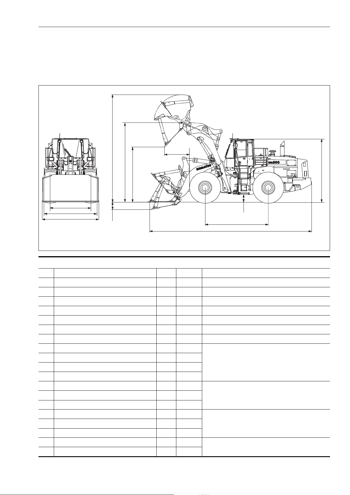
1.6 Dimensions, weights and operating data
1.6.1 WA500-6: Dimensions, weights and operating data
d
c
b
a
H
E
D
C
Bucket capacity to ISO 7546 m³ 5.3 without teeth and without BOC
Material density t/m³ 1.8
Bucket weight without teeth kg 2,676
Static tipping load, straight kg 24,000
Static tipping load, 40° angle kg 20,930
Breakout force, hydraulic kN 286.8
Lifting capacity, hydraulic, on ground kN 348.7
Operating weight *) kg 31,700
a Reach at 45° discharge mm 1,350
b Dumping height at 45° discharge mm 3,460
c Lift height, hinge pin mm 4,770
d Height to upper edge of bucket mm 6,510
e Digging depth mm 122
A Overall length, bucket on ground mm 9,537
B Wheel base mm 3,780
C Bucket width mm 3,430
D Width over tyres mm 3,150
E Gauge mm 2,400
F Ground clearance mm 460
H Overall height mm 3,804
e
Measurements, operating data
These values refer to machines with
29.5 R25 L3
*) Machine without additional counterweight
F
B
A
GK050307
WA500-6H – VEAM430100 1-19
1.7 CE-Conforming equipment Foreword
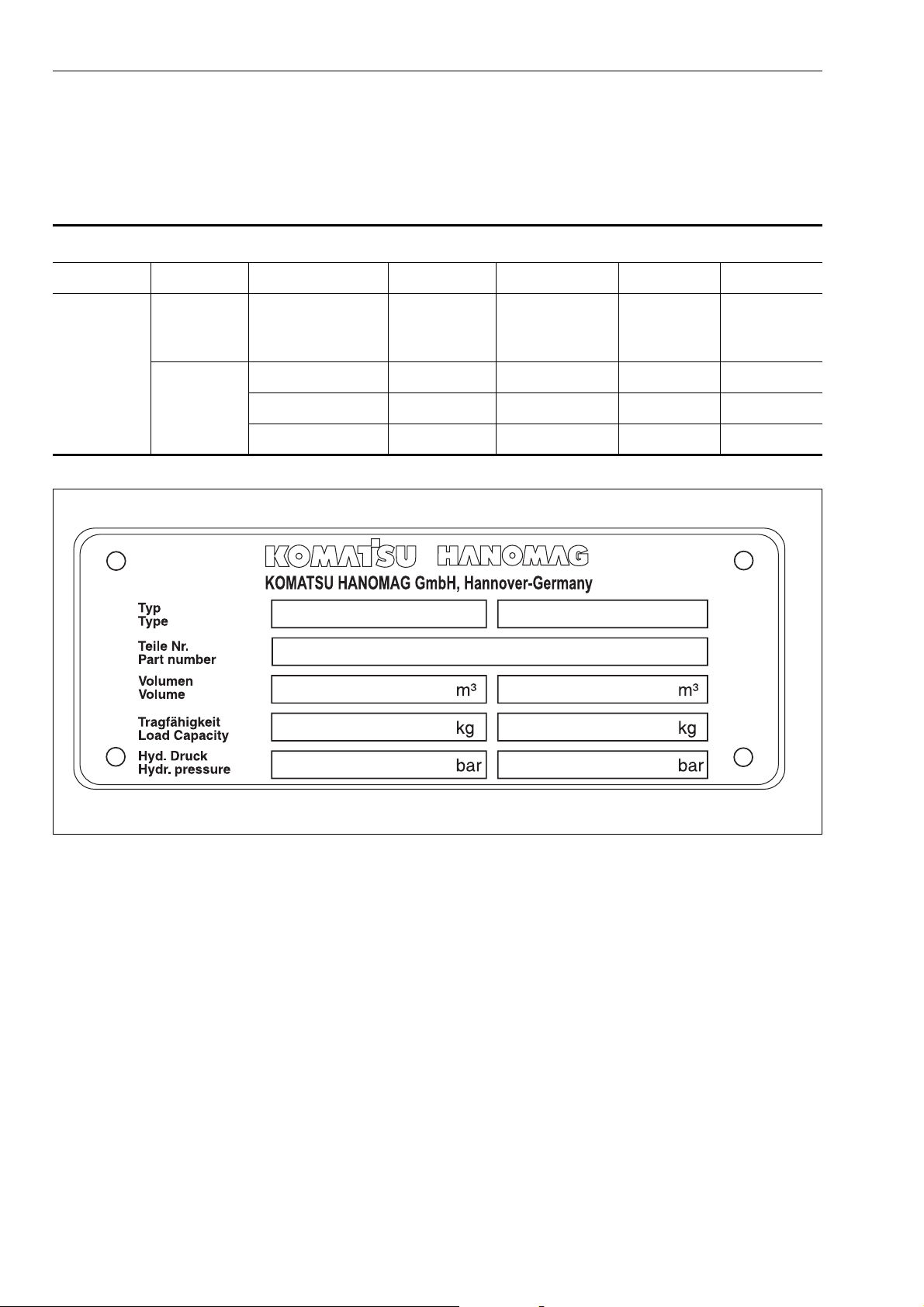
1.7 CE-Conforming equipment
1.7.1 CE-Conforming equipment
CE-Conforming equipment
12 345–
Type Part No.
Bucket WA500-6H
Volume
m³
425-71-H2800 5.3 9,540 - 2,695
425-71-H2810 5.3 9,540 - 2,873
425-71-H2820 5.3 10,080 - 3,012
Load
Capacity
kg
Hydraulic
pressure
bar
Weight
kg
1
2
3
4
5
GK032012
1-20 WA500-6H – VEAM430100
Foreword 1.7 CE-Conforming equipment
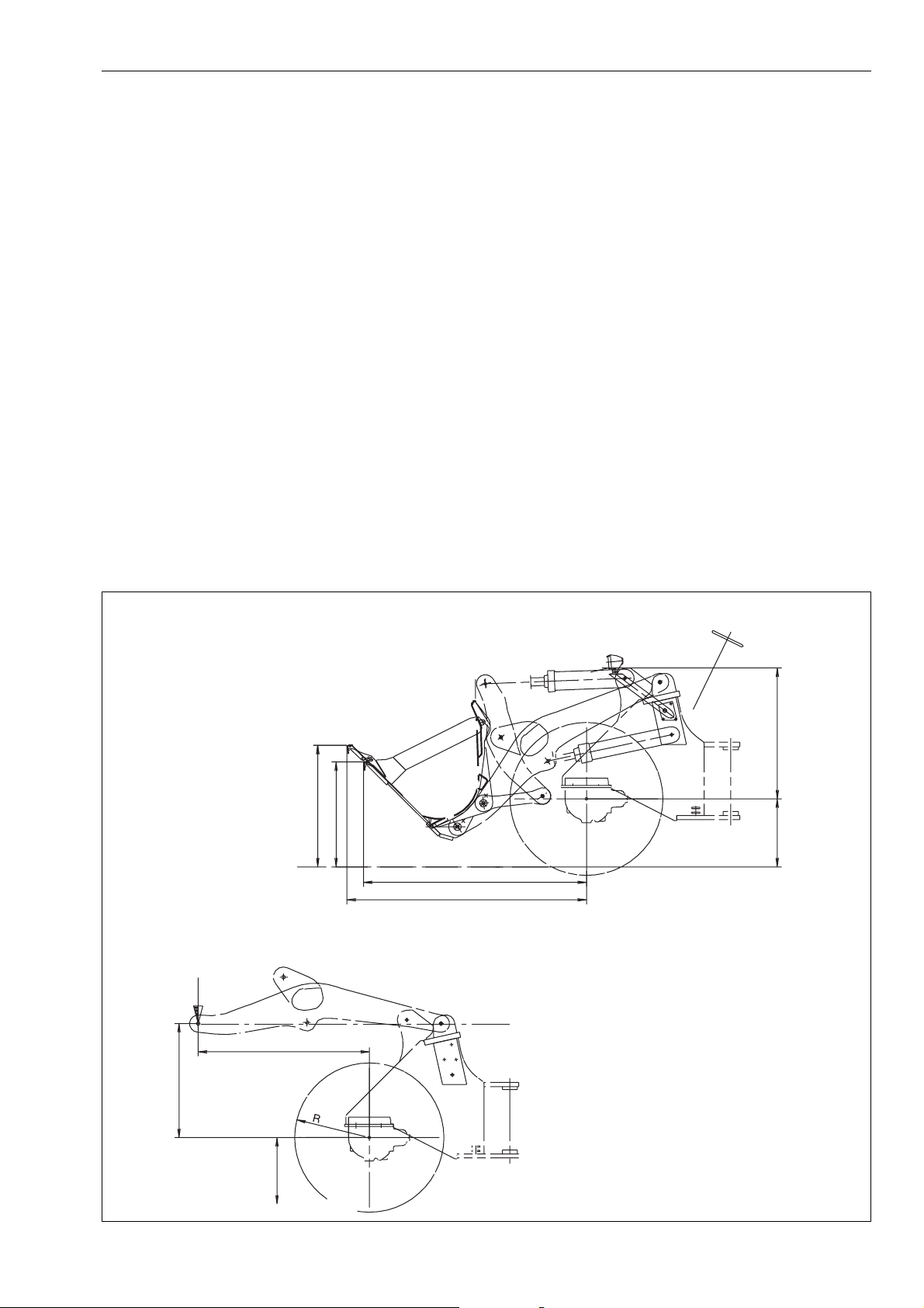
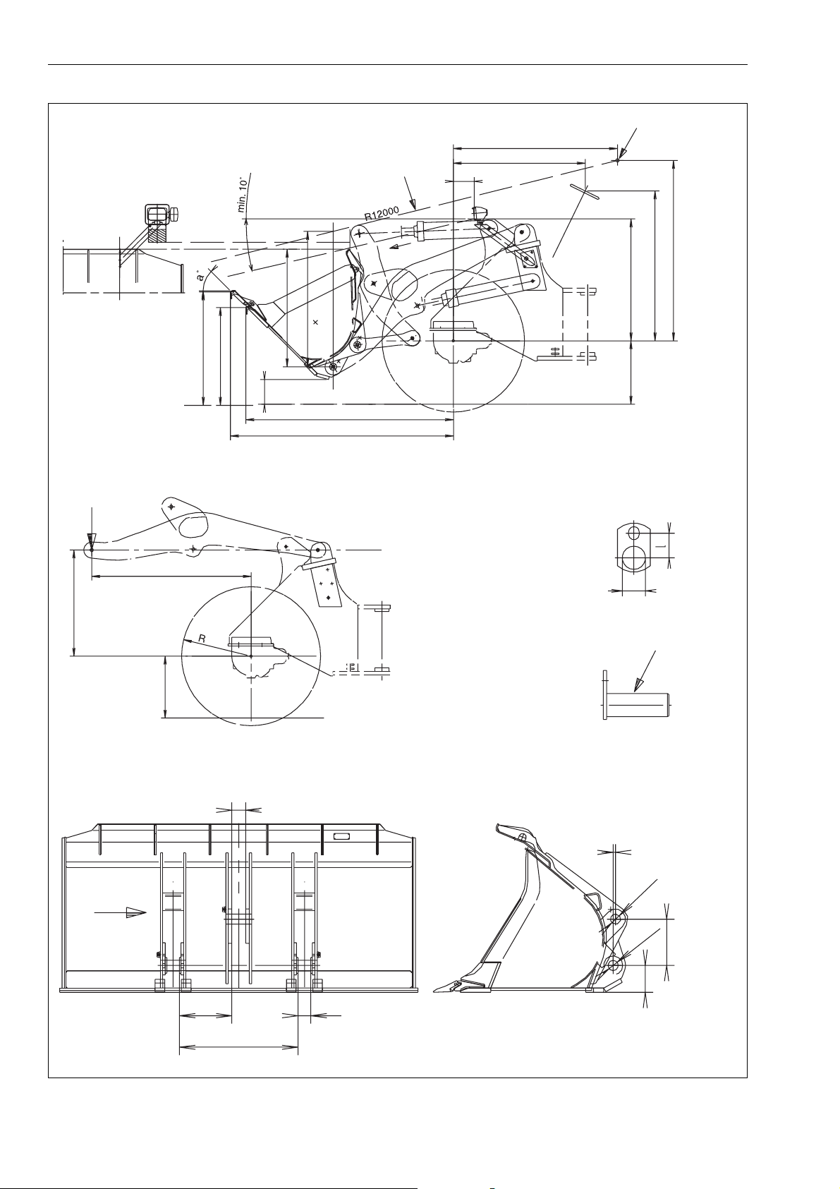
1.7.2 Manufacturer-supplied CE-Conforming equipment, according to document 419-93-H1250
The responsibility for observing valid regulations in the case of
wheel loaders with "interchangeable equipment" (e.g. bucket or
fork-lift) which was not supplied from works lies with the customer which was subsequently fitted to the machine.
The directives for CE conformity and road-traffic registration are
deemed to have been fulfilled when the manufacturer of the
equipment confirms fulfilment of the form 419-93-H1250 alongside.
The certification must be sent to the customer and the wheel
loader manufacturer. The CE conformity declaration for a specific wheel loader is only legally valid once this has taken place.
The dimensions X1, X2, Y1 and Y2 must be provided by the customer for approval for use on public roads. (valid in Germany)
The dimension Sh (smallest tyre radius) must be added to the
dimension D2.
The figure G (in kg) represents the maximum load (equipment
and operating load) which may act upon this point.
Y2
X2
X1
Y1
G
D2
Sh
A1
A2
Sh
GK032013
WA500-6H – VEAM430100 1-21
1.7 CE-Conforming equipment Foreword
1
B1
C1
D2
Sh
B2
C2
Y2
X2
2
H2
H1
J
X1
Y1
D1
A2
G
A1
d1=d2
3
Sh
b3
e
d2
3
d1
c
h
b4
b1
b2
GK032014
1-22 WA500-6H – VEAM430100

Foreword 1.7 CE-Conforming equipment
Manufacturer- supplied CE-Conforming equipment, according to document 419-93-H1250
WA500-6H 419-93-H1250
A1 2,430
A1 Distance: bucket pivoting point - front axle, horizontal
A2 1,510
A2 Distance: bucket pivoting point - front axle, vertical
Sh 884
Sh Distance: road level - front axle
B1 2,081
B1 Distance: driver’s eye (1) - front axle, horizontal
B2 2,464
B2 Distance: driver’s eye (1) - front axle, vertical
C1 1,826
C1 Distance: centre steering wheel - centre front axle,
horizontal
C2 Distance: center steering wheel - centre front axle,
vertical
D1 Distance: headlight - centre front axle, horizontal
D2 Distance: headlight - centre front axle, vertical
G Weight of equipment and working load
H1 Distance: bucket pivoting point - bucket upper edge,
C2 2,064
D1 355
D2 1,617
G 12,391 kg
H1 1,739
H2 1,836
J270
vertical (carrying position)
X1 3,043
H2 Distance: bucket pivoting point - vision line, vertical
(carrying position)
X2 1,300
J Distance: road level - bucket bottom edge (carrying
position)
X1 Distance: cutter - front axle, horizontal
X2 Distance: cutter - road level, vertical
Y1 Distance: teeth - front axle, horizontal
Y2 Distance: teeth - road level, vertical
b1 Bucket connection dimension, boom width inside
b2 Bucket connection dimension, boom arm
b3 Bucket connection dimension, tilt rod
b4 Bucket connection dimension, temporary size
c Bucket connection dimension between d1 and d2,
vertical
d1 Bucket connection dimension, bolt (3) for boom
d2 Bucket connection dimension, bolt (3) for tilt rod
e Bucket connection dimension d1 - d2, horizontally
displaced
h Distance: bucket bottom edge - boom bolt hole
l Distance: centre of bolt - centre of fastening screw
Y1 3,266
Y2 1,517
b1 997
b2 183
b3 183
b4 407
c437
d1 120
d2 120
e0
h295
l120
1Driver’s eye
2 Vision line
3Bolts
Tyres 29.5 R25 L3
Bucket 425-71-H2810
WA500-6H – VEAM430100 1-23

1.7 CE-Conforming equipment Foreword
1-24 WA500-6H – VEAM430100

Safety
2. Safety
WARNING
Please read and make sure that you fully understand the precautions described
in this manual and the safety labels on the machine. When operating or servicing
the machine, always follow these precautions strictly.
WA500-6H – VEAM430100 2-1

2.1 Safety labels Safety
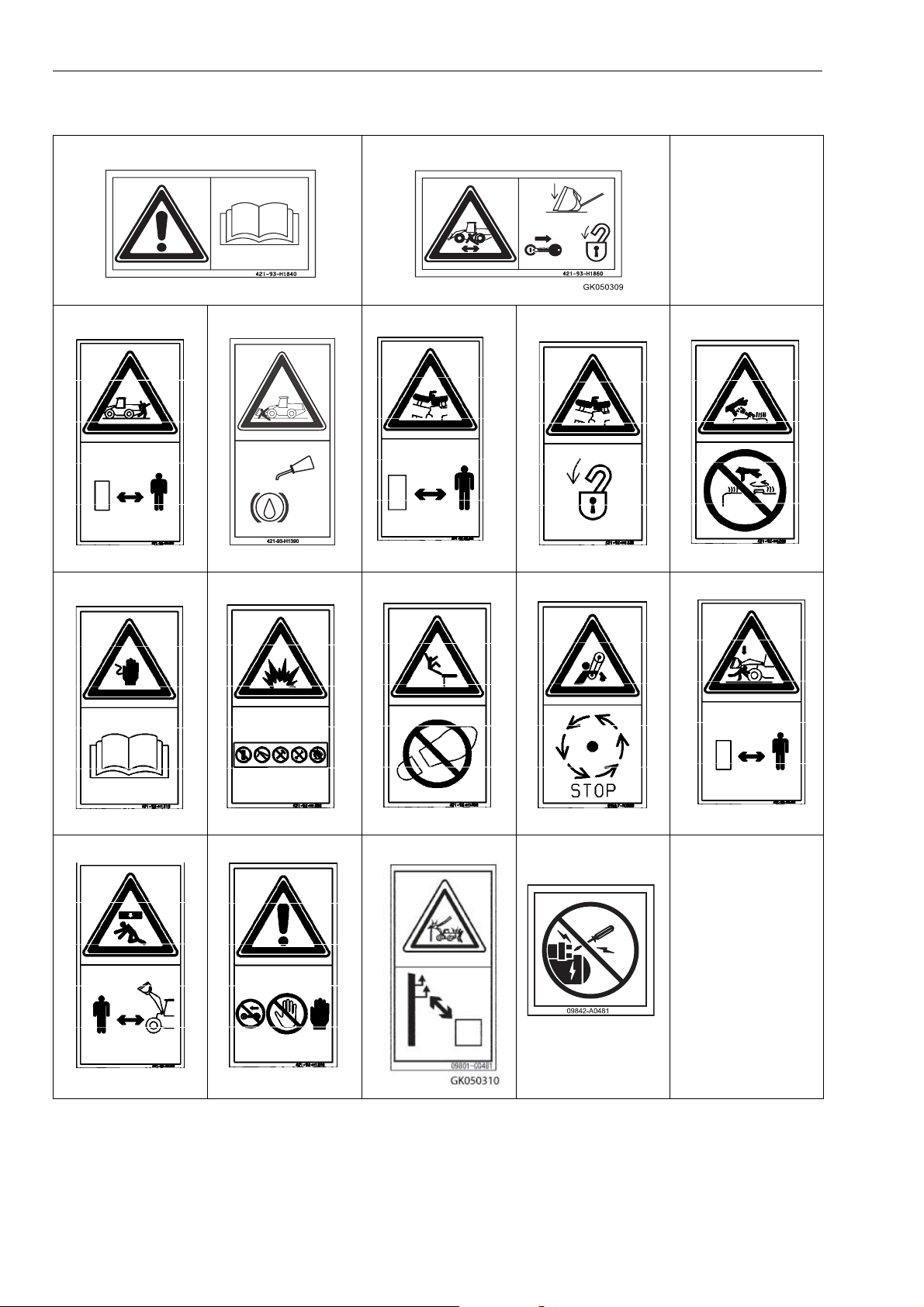
2.1 Safety labels
The following safety labels are used on this machine. Be sure
that you fully understand the correct position and content of
these safety labels.
To ensure that the content of these safety labels can be read
properly, be sure that they are in the correct place and always
keep them clean. When cleaning them, use soap and water. Do
not use organic solvents or gasoline. These may cause the
safety labels to peel off.
If the safety labels are damaged or lost, or cannot be read,
replace them with new parts. For details of the part numbers,
see this manual or check on the actual part, and order the new
part from your KOMATSU distributor.
There are also other labels in addition to the safety labels. Handle these labels in the same way.
2.1.1 Location of safety labels
13
12
6
14
3
15
8
11
10
16
1
2
9
7
"Z"
4
5
"Z"
2-2 WA500-6H – VEAM430100
GK032015

Safety 2.1 Safety labels
GK032018
GK032024
GK032028
GK032030
2.1.2 Presentation of safety labels
12
GK050308
3
45
GK032019
GK032020
67
GK032021
8 9 10 11 12
GK032022
GK032023
GK032025
GK032026
13 14 15 16
GK032029
WA500-6H – VEAM430100 2-3
GK03202
2.1 Safety labels Safety
GK032018
GK032019
GK032023
GK032024
GK032028
GK032030
12
GK050308
3
45
GK032020
67
GK032021
8 9 10 11 12
GK032022
GK032025
13 14 15 16
GK032026
GK032029
GK03202
2-4 WA500-6H – VEAM430100
 Loading...