

Page 1

TESTING AND ADJUSTING STANDARD VALUE TABLE FOR ENGINE
+50
+50
STANDARD VALUE TABLE FOR ENGINE
Machine Model WA380-5H
Engine SAA6D114E-3
Item Measurement Condition s Unit
High idling
Revolving speed
Exhaust tem perature
(Turbocharger outlet
temperature)
Intake air pressure
(Boost pressure)
Exhaust gas color
Valve clearance
Compression
pressure
Blow-by pressure
Oil pressure
Oil temperature All revolution ranges (Inside oil pan)
Fuel injection timing Before compression top dead center
Belt tension
Low idling 920
Rated revolving speed 2,000 2,000
All revolution ranges (Atmospheric temperat ure :
20
°C)
At rated output
At sudden acceleration
At high idling
Air intake valve
Exhaust valve
(Normal temperature)
Oil temperature: 40 ~ 60
(SAE30 oil)
(Engine speed)
At rated output
(Operating range of water tempe rat ure)
(SAE30 oil)
(Operating range of water tempe rat ure)
At high idling (15W-40)
At low idling (15W-40)
At high idling (SAE10W)
At low idling (SAE10W)
Deflection made by finger pressure of about
58.8 N {about 6 kg}
Deflection made by fin-
ger pressure of about 98
N {about 10 kg}
°C
Idler pulley - Crank pulley
Air conditioner compressor - Crank pulley
rpm
°C Max. 550 Max. 600
kPa
{mmHg}
Bosch index
mm
MPa
2
}
{kg/cm
(rpm)
kPa
O}
{mmH
2
MPa
2
}
{kg/cm
°C 90 ~ 120 Min. 120
°(deg.) 8.5 ± 1 8.5 ± 1
mm
Standard V alue F or New
Machine
2,250 ± 50 2,250 ± 50
920
0
113.1 ~ 126.4
{850 ~ 950}
Max. 4.5
Max. 1.0
0.33 ± 0.05
0.56 ± 0.05
Min. 2.4
{24.6}
(250 rpm)
Max. 0.98
{Max. 100}
0.36 ~ 0.61
{3.5 ~ 6.0}
Min. 0.15
{1.5}
0.30 - 0.56
{3.0 - 5.5}
Min. 0.10
{1.0}
8
16 ~ 20 16 ~ 20
Difference between cyl-
inders: Max. 0.7 {6.9}
Service Limit Value
0
Max. 106.4
{Max. 800}
Min. 133.3
{Min. 1,000}
Min. 6.5
Max. 1.5
0.33 ± 0.05
0.56 ± 0.05
Min. 2.0 {20.5}
(250 rpm)
Max. 1.96
{Max. 200}
0.21
{2.1}
0.07
{0.7}
0.18
{1.8}
0.07
{0.7}
Above 1 0
or
below 6
20-2 WA380-5H
Page 2
TESTING AND ADJUSTING STANDARD VALUE TABLE FOR CHASSIS
5
5
5
5
STANDARD VALUE TABLE FOR CHASSIS
The * mark shows the value before the detent.
Machine Model WA380-5H
Category Item Measuremen t Conditions Unit
N - FORWARD,
REVERSE
N - FORWARD,
REVERSE
1st ~ 2nd
2nd ~ 3rd {0.6
3rd ~ 4th { 0. 6
• Engine Stopped
• Measure at center of
lever knob
• Engine stopped
• Measure at center of
lever knob
1st ~ 2nd
2nd ~ 3rd 35
Directional
lever
Speed lever
Operating effort
Travel
Operating effort
Travel
3rd ~ 4th 35
HOLD → RAISE
• Engine speed: Low
idling
Operating
effort
RAISE → HOLD
HOLD → LOWER
Lift arm
LOWER → HOLD
LOWER → FLOAT
FLOAT → HOLD
• Hydraulic oil tempera ture:
°C
45 ~ 55
Working
equipment
control lever
Bucket
HOLD → DUMP
HOLD → TILT
N
{kg}
mm 35
N
{kg}
mm
N
{kg}
Standard Value For New
Machine
+ 4 . 9
.9
-3.0
{0.6
+0.5
-0.3
Service Limit Value
} Max. 16.7 {1.7}
± 10 35 ± 20
+ 4 . 9
.9
-3.0
+ 4 . 9
.9
-3.0
+ 4 . 9
.9
-3.0
35
+0.5
{0.6
} Max. 16.7 {1.7}
-0.3
+0.5
} Max. 16.7 {1.7}
-0.3
+0.5
} Max. 16.7 {1.7}
-0.3
± 10 35 ± 20
± 10 35 ± 20
± 10 35 ± 20
Max. 12.8 {1.3} * Max. 19.6 {2.0} *
Max. 14.7 { 1 .5} Max. 22.6 {2.3}
Max. 12.8 {1.3} * Max. 19.6 {2.0} *
——
Max. 15.7 { 1 .6} Max. 23.5 {2.4}
Max. 14.7 { 1 .5} Max. 22.6 {2.3}
Max. 17.7 { 1 .8} Max. 26.5 {2.7}
Max. 12.8 {1.3} * Max. 19.6 {2.0} *
Steering
wheel
Frame
TILT → HOLD
HOLD → RAISE
Lift arm
Travel
Bucket
HOLD → RAISE
HOLD → RAISE
HOLD → RAISE
HOLD → RAISE
Play
Operating effort
Turning speed (Not including play)
Low idling
Operating
time
High idling
Clearance betwee n front frame and rear
frame
• Engine speed: Low
idling
• Hydraulic oil tempera ture:
°C
45 ~ 55
• Engine stopped
• Machine facing straight
to front
• Flat, horiz o n tal,
straight, dry paved road
surface
• Engine speed: Low
idling (Bucket empty)
• Engine speed: High
idling
• Left lock - right lock
• Engine speed:
Low idling
• Hydraulic oil
temperature:
45 ~ 55 °C
• Left lock - Right
lock
• Engine speed: 1,200 rpm"
• Hydraulic oil temperature: 45 55 °C
• Flat, level, straight, dry, and
paved road
• At max. steering angle
P mode
N mode
Max. 14.7 { 1 .5} Max. 22.6 {2.3}
43
± 9 * 43 ± 18 *
43 ± 9 * 43 ± 18 *
mm
50 ± 950 ± 18
50 ± 950 ± 18
43 ± 9 * 43 ± 18 *
mm Max. 40 Max. 100
N
{kg}
Turns
Sec.
mm 25 ± 2
∼ 12.6
6.9
{0.7 ~ 1.3}
Max. 19.6 {2.0}
4.0 ± 0.4 4.0 ± 0.4
4.5
± 0.4
3.6 ± 0.3
3.7 ± 0.3
Max. 7.0
Max. 5.3
Max. 5.7
—
WA380-5H 20-3
Page 3
TESTING AND ADJUSTING STANDARD VALUE TABLE FOR CHASSIS
Machine Mod el WA380-5H
Category Item Measurement Condition Unit
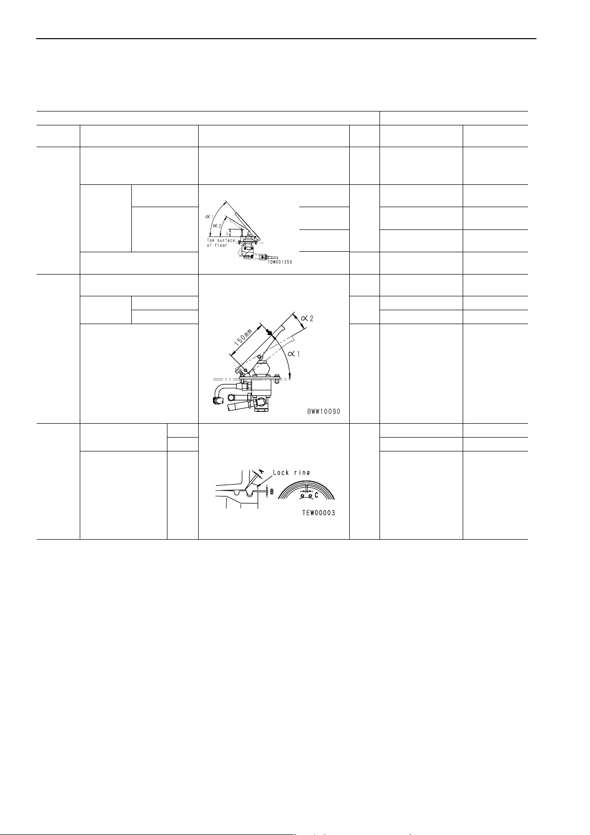
Pressing effort
• Measure while engine is running.
• Measure at 150 mm from fulcrum of
pedal.
N
{kg}
Standard Value For
New Machine
60.8 ~ 80.4
{6.2 ~ 8.2}
Service Limit
Value
Max. 117.6
{12.0}
Accelera-
tor pedal
Brake
pedal
α1)
Neutral (
Pressing
angle
Height of stopper (L) mm 60
Operating effort
Operating
angle
Play mm 5
Fitting of wheel lock
ring
Neutral (
α2)
α1)
Neutral (
Neutral (α2) —
• Measure while engine is stopped.
°C
deg.
N
{kg}
deg.
P-mode
N-mode
• Engine speed: Low idling
• Hydraulic oil temperature : 45 ~ 55
BWW10090
A
• Tire inflation pressure: Specified pres-
BMax. 4.0—
sure
33
37
294
{30
15
Max. 2.5 —
48 —
± 1—
± 1—
± 5—
± 29.4
± 3}
45 —
+1
0
± 0.5—
Max. 421.4 {43}
Tire
Clearance of whee l
lock ring
C2 ~ 10—
TEW00003
mm
20-4 WA380-5H
Page 4

TESTING AND ADJUSTING STANDARD VALUE TABLE FOR CHASSIS
+5
-10
5
0
+ 0 . 9 8
0
5
+ 0 . 9 8
0
0
+ 1 . 5
5
5
Machine Model WA380-5H
Category Item Measurement Conditions Unit
Torque converter
• Engine water temperature:
Operating range
• Torque converter oil
N mode
P mode 2,120
temperature:
Engine speed
Hydraulic stall
Torque converter stall +
hydraulic stall
°C
60 ~ 80
• Hydrauli c oil temperature:
°C
45 ~ 55
N mode 1,810
P mode 2,150
N mode 1,715
P mode 1,715
Standard Value For New
rpm
Machine
± 50 1,815 ± 100
1,815
Service Limit Value
± 50 2,120 ± 100
± 100 1,810 ± 200
± 100 2.150 ± 200
± 100 1,715 ± 200
± 100 1,715 ± 200
Main relief
valve
Torque converter relief (Inlet
port) pressure
Transmis-
sion, torque
converter
Torque converter outlet port
oil pressure
ECMV output
(Clutch) oil
pressure
Steering Steering relief pressure
Charge cut-in pressure
Accumulator
Charge cut-out pressure
Low idling
Rated speed
1st, 2nd, 3rd,
4th
F - R
Lock-up
• Torque converter oil te m perature:
60 ~ 80
°C
• Engine: Rated speed
• Torque converter oil te m perature:
°C
60 ~ 80
• Engine: Rated speed
• Manual swit ch O N
• Hydraulic oil temperature:
°C
45 ~ 55
• Engine speed: High idling
• Engine speed:
Low idling
• Hydraulic oil
temperature:
45 ~ 55 °C
• Point where brake
oil pressure warning lamp goes out
• Point where oil
pressure is going
up and then starts
to go down
MPa
{kg/cm2}
MPa
{kg/cm2}
MPa
{kg/cm2}
2.74 ± 0.2
± 2}
{27.9
± 0.20
2.86
{29.2
± 2.0}
Max. 0.88
{Max. 9.0}
0.44
± 0.05
± 0.5}
{4.5
± 0.15
2.11
{21.5
± 1.5}
± 0.15
1.91
{19.5
± 1.5}
± 0.15
1.72
± 1.5}
{17.5
15.7 ± 0.49
± 5}
{160
+0.5
5.9
0
+
{60 }
9.8
0
+1
{100 }
2.74
± 0.2
± 2}
{27.9
± 0.20
2.86
{29.2
± 2.0}
Max. 0.88
{Max. 9.0}
0.44
± 0.05
± 0.5}
{4.5
± 0.15
2.11
{21.5
± 1.5}
± 0.15
1.91
{19.5
± 1.5}
1.72
± 0.15
± 1.5}
{17.5
+0.49
15.7 {160 }
-0.98
5.9
-0.5
+1
{60 }
-
9.8
-0.5
+1
{100 }
-
WA380-5H 20-5
Page 5

TESTING AND ADJUSTING STANDARD VALUE TABLE FOR CHASSIS
Machine Model WA380-5H
Cate-
gory
Power
train
Item Measurement Conditions Unit
1st
P mode
FORW ARD
N mode
Travel speed
(Bucket
empty)
P mode
REVERSE
N mode
2nd 12.3
3rd 21.4
4th 34.0
1st 5.3
2nd 9.3
3rd 16.7
4th 27.0
1st 7.3
2nd 12.8
3rd 22.6
4th 35.0
1st 5.7
2nd 9.9
3rd 17.7
4th 27.9
Brake oil pressure
• Hydraulic oil te mperature:
45 ~ 55
°C
km/h
Standard Value For New
Machine
6.8
± 0.3 6.8 ± 0.5
Service Limit Value
± 0.6 12.3 ± 0.9
± 1.1 21.4 ± 1.6
± 1.7 34.0 ± 2.6
± 0.3 5.3 ± 0.4
± 0.5 9.3 ± 0.7
± 0.8 16.7 ± 1.3
± 1.4 27.0 ± 2.0
± 0.4 7.3 ± 0.5
± 0.6 12.8 ± 1.0
± 1.1 22.6 ± 1.7
± 1.8 35.0 ± 2.6
± 0.3 5.7 ± 0.4
± 0.5 9.9 ± 0.7
± 0.9 17.7 ± 1.3
± 1.4 27.9 ± 2.1
5.1 ± 0.49 {52 ± 5} 5.1 ± 0.98 {52 ± 10}
Wheel
brake
Drop in brake
pressure
Performance
Disc wear
• Engine stopped
• Keep brake pedal depre sse d a t 4. 9
MPa {50 kg/cm
2
} and measure drop in
oil pressure after 5 min.
• Tire inflation pressure: Specified pressure
• Flat, horizontal, straight, dry paved
road surface
• Speed when applying brake: 20 km/
h, braking delay: Withi n 0. 1 sec .
• Brake pedal operating effort: Specified
operating effort (333
± 33.3 N {34.0 ±
3.4kg})
• Measure braking distance
2
• Oil pressure: 4.9 MPa {50 kg/cm
}
• Pedal depressed fully
MPa
{kg/cm2}
Max. 98 {1.0} Max. 98 {1.0}
m Max. 5 Max. 5
mm Shaft protrusion 0
Shaft protru sion reac hes wear
limit position (2.4 mm)
20-6 WA380-5H
Page 6

TESTING AND ADJUSTING STANDARD VALUE TABLE FOR CHASSIS
Machine model WA380-5H
Category Item Measurement Conditions Unit
Parking brake inlet pressure
• Torque converter oil t em perature: 60 ~
°C
80
• Engine speed: Low idling
MPa
{kg/cm
• Tire inflation pressure: Specified pressure
• Flat paved road with 1/5 (11
° 20’) grade
• Dry, paved road surface
• Machine at operating condition
Parking
brake
input
pressure
Performance
TEW01360
— Holds in position Holds in position
Standard Value For
2
}
New Machine
Min. 2.27
{Min. 23.1}
Service Limit Value
Min. 2.27
{Min. 23.1}
PPC
Disc thickness mm 3.2
PPC valve basic pressure
Lift arn
PPC
valve
output
pressure
RAISE,
FLOAT;
Bucket
DUMP, TILT
Lift arm
LOWER
• Hydraulic oil te mperature:
°C
45 ~ 55
• Engine speed: High idling
• Hydraulic oil te mperature:
°C
45 ~ 55
• Engine speed: High idling
• Control lever operated fully
MPa
{kg/cm
2
}
3.72
3.72
+0.2
0
+0.1
-0.1
2.2
{22.5
± 0.08 2.97
{38
{38
± 0.25
± 2.5}
+2
}3.72
0
+1
}3.72
-1
+0.2
-0.2
+0.1
-0.2
2.2
{22.5
± 0.39
{38
{38
± 4}
-2
-2
+2
+1
}
}
WA380-5H 20-7
Page 7

TESTING AND ADJUSTING STANDARD VALUE TABLE FOR CHASSIS
9
7
5
3
Machine Model WA380-5H
Category
Work equipment relief pressure
Item Measurement Conditions Unit
• Hydraulic oil temperature: 45 ~ 55
• Run engine at high idling.
°C
MPa
{kg/cm2}
Standard Value For
New Machine
20.6 ± 0.49
{210
± 5}
Service Limit Value
+0.4
20.6 210 }
+
-1.2
-1
• Hydraulic oil temperature: 45 ~ 55
• Run engine at high idling.
°C
N mode
± 0.5 Max. 8.0
6.2
• Apply no load.
Lift arm RAISE
Raising time
P mode 5.3
± 0.5 Max. 7.0
Lowering time
N mode 2. 8
± 0.5 Max. 4.0
Lift arm LOWER
Work equipment speed
Bucket full
stroke
Forward
• Hydraulic oil temperature: 45 ~ 55
• Engine speed: High idling
•No load
To stroke end
°C
P mode 2.7
sec.
N mode 1. 6
P mode 1.4
N mode 2. 2
± 0.5 Max. 3.8
± 0.3 Max. 2.3
± 0.3 Max. 2.0
± 0.3 Max. 3.0
Backward
Work equi pment
From level position
Moving
bucket from
level position
Backward
P mode 1.9
N mode 1. 4
P mode 1.2
± 0.3 Max. 2.6
± 0.3 Max. 2.0
± 0.3 Max. 1.8
• Hydraulic oil temperature: 45 ~ 55
°C
• Stop engine and leave for 5 minutes, then measure for 15
minutes.
Retraction of lif t
cylinder rod
• Apply no load to bucket an d set lift arm and bucket in
level position.l
Max. 14 Max. 17
mm
Hydraulic dr ift
Retraction of bucket cylinder rod
Max. 36 Max. 43
20-8 WA380-5H
Page 8

TESTING AND ADJUSTING STANDARD VALUE TABLE FOR CHASSIS
Machine Model WA380-5H
Category Item Measurement Conditions Unit
• Engine speed: High idling
• Engine water temperature: Min. 95
°C
Max. fan speed
Oil pressure drive fan
Min. fan speed
• Hydraulic oil temp erature: Min. 95
°C
• Torque converter oil temperature:
Min. 105
• Engine speed: Low idling
• Engine water temperature: Max. 40
°C
• Hydraulic oil temperature: Max. 40
°C
• Torque converter oil temperature:
Max. 40
°C
°C
rpm
Standard Value For
New Machine
± 100 1,400 ± 200
1,400
240
± 50 240 ± 100
Service Limit Value
WA380-5H 20-9
 Loading...