

Page 1
WA150-5
WA
250
FLYWHEEL HORSEPOWER
Gross: 74 kW 99 HP @ 2000 rpm
Net: 71 kW 96 HP @ 2000 rpm
OPERATING WEIGHT
7410 – 7495 kg
16,336 – 16,524 lb
BUCKET CAPACITY
1.3 –1.7 m
3
1.7 –2.2 yd
3
Photo may include optional equipment.
WA
150
WHEEL LOADER
Page 2
Larger cab
with new layout design
Extended service intervals
Powerful yet efficient Komatsu
SAA4D102E-2
emissionized engine
Full side opening
gull-wing engine doors
Expanded main monitor
and troubleshooting display
Reduced operator noise
to 70 dB(A)
New tilt steering column
Ground level servicing
and fluid checks
Staircase-type steps
with large rear-hinged doors
Side-by-side type coolers
for easy access and cleaning
Extremely low
fuel consumption
Easy-to-operate loader control mono-lever
using PPC (Proportional Pressure Control)
Large breakout force
Maintenance-free
fully hydraulic
wet-disc service and parking brakes
Electronically controlled Hydrostatic Transmission
(HST) with variable shift control system
Traction control system
Radial Sealed
air cleaner
Overrun protection system
Swing-out hydraulic
radiator fan
Flat face "O-Ring" Hydraulic Seals
for extended life
Sealed DT electrical connectors
W HEEL L OADER
WALK-AROUND
WHEEL LOADER
FLYWHEEL HORSEPOWER
Gross: 74 kW 99 HP @ 2000 rpm
Net: 71 kW 96 HP @ 2000 rpm
OPERATING WEIGHT
7410 – 7495 kg
16,336 – 16,524 lb
BUCKET CAPACITY
1.3 – 1.7 m
3
1.7 – 2.2 yd
3
WA150-5
WA150-5
32
Komatsu-integrated
design offers the best
value, reliability, and versatility.
Hydraulics, powertrain, frame,
and all other major components
are engineered by Komatsu.
You get a machine whose
components are designed
to work together for higher
production, greater reliability,
and more versatility.
Photos may include optional equipment.
Page 3
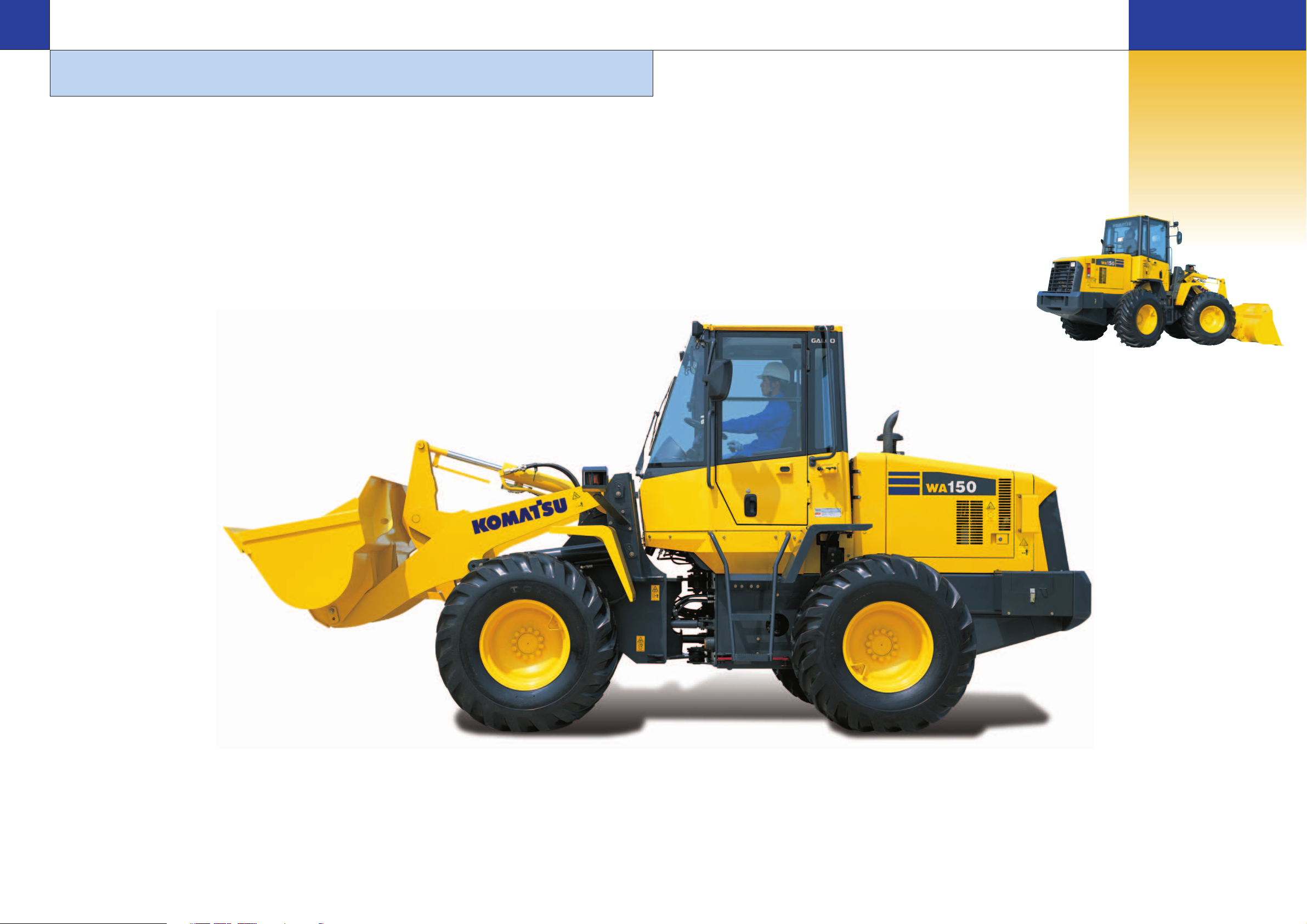
Powerful Engine
A powerful SAA4D102E-2 turbocharged air-to-air aftercooled
diesel engine provides an output (net) of 71 kW 96 HP for
the WA150-5.
Low Fuel Consumption
The fuel consumption is reduced up to 10%* due to the hightorque engine and Hydrostatic Transmission (HST) with maximum efficiency in the low-speed range.
*V-shape loading (25 sec. cycle time)
Electronically-Controlled HST Using a 1-Pump,
2-Motor System
● The 1-pump, 2-motor system allows for high-efficiency
and high tractive effort. Engine power is transmitted
hydraulically to a transfer case, then manually out to the
differentials and out to the four driving wheels.
● HST provides quick travel response and aggressive drive
into the pile. The variable displacement system automatically adjusts to the tractive effort demand to provide
maximum power and efficiency.
● Full auto-shifting eliminates any gear shifting and kickdown operation to allow the operator to concentrate on
digging and loading.
● When high drive torque is needed for digging, climbing
or initiating movement, the pump feeds both motors. This
combination makes the loader very aggressive and
quick.
● Under deceleration, the HST system acts as a dynamic
brake on the mechanical drive system. The dynamic
brake can hold the loader in position on most workable
slopes. This can be an advantage in stockpiling and
ramp loading.
● As the machine moves and gains ground speed, the
torque demand decreases and the low speed motor is
effectively removed from the drive system by a clutch. At
this point, the flow is going to the high-speed motor and
the low-speed motor is not causing a drag on the system.
● An inching pedal gives the operator excellent simultaneous control of his travel and equipment hydraulic speeds.
By depressing the inching pedal, drive pump flow to the
motors will decrease, reducing ground speed and allowing the operator to use his accelerator to increase flow to
his equipment hydraulics. Depressing the inching pedal
further will activate the service brakes.
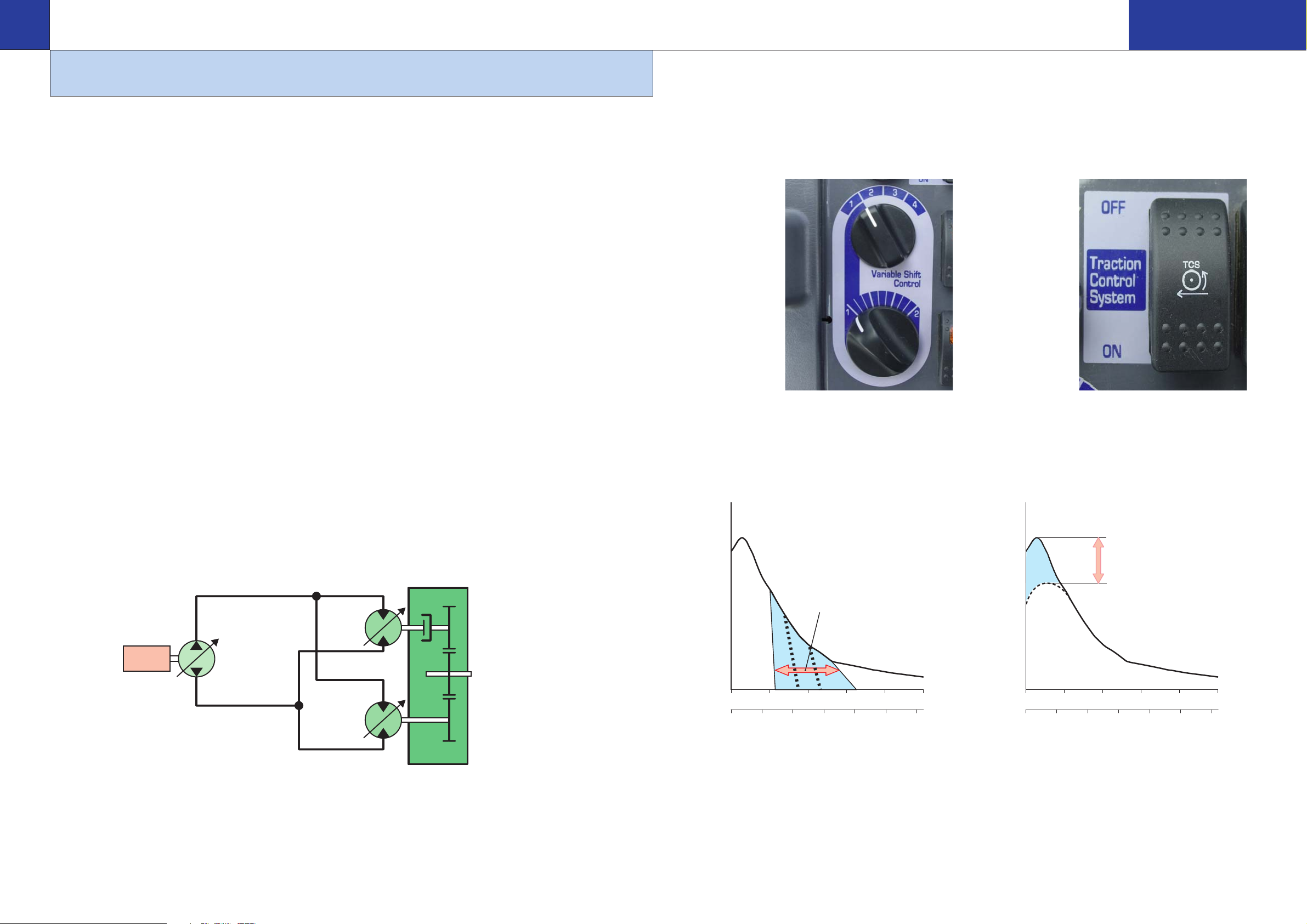
High Productivity and Low Fuel Consumption
Electronically-Controlled HST with Variable Shift
Control System
The operator can choose between first, second, third or
fourth maximum speeds by dialing the speed range selector
switch.
For v-cycles, the operator can set the speed control switch to
1 or 2, which will
give him aggres-
sive digging, quick
response and fast
hydraulics. For
load and carry, he
can select 3 or 4
which will still give
aggressive digging
but with much
faster travel
speed.
The variable shift
switch allows the
operator to adjust his machine speed in confined v-loading
applications. When in 1, the operator can adjust his travel
speed using the variable shift switch to match his machine
speed and hydraulics to the distance he must travel.
Traction Control System
In limited traction situations where the operator would like
to avoid tire slippage (such as sandy or wet surface opera-
tions), he can automatically reduce slippage by activating
the traction control feature. Putting the traction control
switch in the “ON” position limits the maximum amount of
tractive effort.
Traction control will
be an advantage in
certain appplica-
tions such as trans-
fer stations where
the loader may be
working on slippery
concrete.
Traction Control
Variable Shift Control
PRODUCTIVITY FEATURES
WHEEL LOADER
WA150-5
54
W HEEL L OADER
WA150-5
Engine
Piston Pump
Low speed
piston
motor
High speed
piston
motor
Transfer case
To differentials
Tractive effort
0
4 8 12 16 20
0 8 10 12642
Variable range
of travel speed
Travel speed
km/h
MPH
Tractive effort
0
4 8 12 16 20
0 8 10 12642
Reduced
km/h
MPH
Travel speed
Page 4

Fully Hydraulic Wet Multi-disc Service Brakes
The dual wet disc brakes at each wheel are fully sealed and
adjustment free to reduce contamination, wear and mainte-
nance. The result is lower maintenance costs and higher reli-
ability.
Added dependability is designed into the braking system by
the use of two independent hydraulic circuits, providing
hydraulic backup should one of the circuits fail.
If the brake oil pressure drops, the warning lamp flashes and
the warning buzzer sounds intermittently.
The parking brake is mechanically controlled by a lever in the
cab.
High-rigidity Frames
The front and rear frames along with the loader linkage have
high rigidity to withstand repeated twisting and bending loads
to the loader body and linkage. Both the upper and lower
center pivot bearings use tapered roller bearings for
increased durability.The structure is similar to those of large
sized loaders and the reinforced loader linkage ensures high
strength.
Flat Face-to-Face O-Ring Seals
Flat face-to-face
O-ring seals are
used to securely
seal all hydraulic
hose connections
and to prevent oil
leakage.
Cathion Electrodeposition Primer Paint/Powder
Coating Final Paint
Cathion electrodeposition paint is applied as a primer paint
and powder coating is applied as a topcoat to the exterior
metal sheet parts. This process results in a durable rust-free
machine, even in the most severe environments. Some
external parts are made of plastic to provide long life and
high impact resistance.
Sealed DT Connectors
Main harnesses and controller connectors are equipped with
sealed DT connectors providing high reliability and dust and
corrosion resistance.
Komatsu Components
Komatsu manufactures
the engine, transfer
case, differentials and
electric parts on this
wheel loader. Komatsu
loaders are manufac-
tured with an integrated
production system under
a strict quality control
system.
Main Monitor - EMMS (Equipment Management
Monitoring System)
Komatsu’s new main monitor keeps the operator informed of
all machine functions at a glance. The monitor is located
behind the steering wheel and displays various different
machine functions including fluid/filter change intervals and
troubleshooting memory display functions. The main gauges
are analog type for easy viewing and other functions utilize
light symbols or LCD readouts.
Swing-Out Radiator
The new Komatsu
cooling system is
isolated from the
engine to provide
more efficient cool-
ing and low noise.
The swing-out
hydraulic fan allows
the operator to
quickly clean out
the cooling system.
The radiator, air-to-air cooler and oil cooler are mounted
side-by-side for more efficient cooling and easy cleaning. A
fully-opening, gas spring assisted rear grill gives the operator
excellent access to the swing-out fan and coolers.
Full Side-Opening Gull-Wing Engine Doors
Ground level engine service and daily service checks are
made easy with the gas spring assisted full side opening
gull-wing doors.
Extended Service Interval
Extended engine oil change interval:
250 H 500 H
Extended drive shaft greasing interval:
1,000 H 4,000 H
Overrun Prevention System
When the machine descends a slope of six degrees or less,
maximum travel speed is automatically restricted to approxi-
mately 43 km/h 27 MPH, for safety protection against dam-
age of power train components and brakes by sensing the
travel speed and controlling the discharge amount of the
HST pump and motor. When the machine descends a steep
slope and the travel speed reaches 40 km/h 25 MPH, the
caution lamp lights up to inform the operator to reduce the
travel speed.
Note: When the machine descends a steep slope, the use
of the service brake is necessary to limit travel speed.
Parking Brake
Service Brakes
INCREASED RELIABILITY AND SERVICEABILITY
WHEEL LOADER
WA150-5
76
W HEEL L OADER
WA150-5
hose
nipple
O-ring
Front axle Rear axle
Komatsu Components
Engine
Transfer
Page 5

New Cab Layout
Komatsu’s new cab layout provides the operator with a
roomy, quiet and efficient work environment. The low noise
level inside the cab leads the industry at 70 dB(A) and loader
controls are ergonomically designed to reduce operator
fatigue and increase productivity.
Two Door Walk-Through Cab
Entry and exit into the new
Komatsu cab starts with
sloped staircase type
steps and large diameter
handrails for added safety
and comfort. The large cab
doors are rear-hinged to
open 130 degrees offering
easy entry/exit and will not
hamper visibility when
operating the machine with
the doors latched open. A
wide pillar-less flat glass provides for excellent visibility. The
wiper arm covers a large area to provide great visibility even
on rainy days.
Low-noise Design
Operator noise: 70 dB(A)
The large cab is
mounted with
Komatsu’s unique
ROPS/FOPS vis-
cous mounts. The
low-noise engine,
hydraulically driven
fan, and hydraulic
pumps are mounted
with rubber cush-
ions, and the cab sealing is improved to provide a quiet,
low-vibration, and comfortable operating environment.
Pressurization in the cab keeps dirt out further enhancing
the operator’s comfort.
Easy-to-operate Loader Control Mono-lever
A new mono-lever using PPC (Proportional Pressure Control)
allows the operator to easily operate the work equipment, to
reduce operator fatigue and to increase controllability. The
adjustable wrist rest provides the operator with a variety of
comfortable operating positions.
Electrically Controlled Directional Lever
The operator can change direction with a touch of his fingers
without removing his hand from the steering wheel. Solid
state electronics makes this possible.
Tiltable Steering Column
The operator can tilt the
steering column to allow max-
imum comfort and control.
The two-spoke steering
wheel allows maximum visi-
bility of the monitor panel and
forward work environment.
Comforts of Home
The large cab allows
room for a large lunch
box holder and a variety
of cup holders. Optional
air conditioning and the
optional AM/FM stereo
cassette system create
a comfortable and con-
trolled work environ-
ment.
OPERATOR COMFORT
WHEEL LOADER
WA150-5
98
W HEEL L OADER
WA150-5
Page 6

16.9-24-10PR(L2)
14.00-24-12PR(L2)
15.5-25-8PR(L2) 17.5-25-12PR(L2)
Tread 1780 5'10" 1780 5'10" 1780 5'10" 1780 5'10"
Width over tires 2250 7'5" 2185 7'2" 2180 7'2" 2220 7'3"
A Wheelbase 2600 8'6" 2600 8'6" 2600 8'6" 2600 8'6"
B Hinge pin height at max. height 3485 11'5" 3510 11'6" 3475 11'5" 3510 11'6"
C Hinge pin height at carry position 360 1'2" 355 1'2" 360 1'2" 355 1'2"
D Ground clearance 400 1'4" 425 1'5" 390 1'3" 425 1'5"
E Hitch height 800 2'7" 825 2'8" 790 2'7" 825 2'8"
F Overall height, top of stack 2420 7'11" 2445 8'0" 2410 7'11" 2445 8'0"
G Overall height, ROPS cab 3035 9'11" 3060 10'0" 3025 9'11" 3060 10'0"
H See Dumping Clearance Below
Change in
Change in Tipping Load
Width Ground Change in Change in
Operating Weight Straight Full Turn Over Tire Clearance
Vertical Dimensions
Reach
14.00-24-12PR (L2) 130 kg 287 lb 95 kg 209 lb 85 kg 187 lb 2185 mm 7'2" 425 mm 1'5" 25 mm 1.0" –25 mm –1.0"
15.5-25-8PR (L2) 10 kg 22 lb 10 kg 22 lb 5 kg 11 lb 2180 mm 7'2" 390 mm 1'3" –10 mm -0.4" 10 mm 0.4"
17.5-25-12PR (L2) 150 kg 331 lb 110 kg 243 lb 95 kg 209 lb 2220 mm 7'3" 425 mm 1'5" 25 mm 1.0" –25 mm –1.0"
Install ROPS canopy (instead of cab) –110 kg –243 lb –110 kg –243 lb –95 kg –209 lb
Additional counterweight 200 kg 441 lb 380 kg 838 lb 330 kg 728 lb
Air conditioner 70 kg 154 lb 80 kg 176 lb 70 kg 154 lb
BUCKET CONTROLS
The use of a PPC hydraulic control valve offers lighter operating effort
for the work equipment control levers. The reduction in the lever effort
and travel makes it easy to operate in the work environment.
Control positions
Boom. . . . . . . . . . . . . . . . . . . . . . . . . Raise, hold, lower, and float
Bucket . . . . . . . . . . . . . . . . . . . . . . . . . . Tilt-back, hold, and dump
HYDRAULIC SYSTEM
Capacity (discharge flow) @ engine-rated rpm
Maximum flow for loader circuit
Loader + steering pump . . . . . . . . . . .
123
ltr/min
32.5 U.S.
gal/min
Pilot pump . . . . . . . . . . . . . . . . . . . . . . .
38
ltr/min
10 U.S.
gal/min
(Gear-type pumps)
Relief valve setting
Loader . . . . . . . . . . . . . . . . . . . .210 kg/cm220.6 MPa 3,000 psi
Steering. . . . . . . . . . . . . . . . . . . . 190 kg/cm218.6 MPa 2,700 psi
Control valve
2-spool open center type
Hydraulic cylinders
Loader and steering . . . . . . . . . . . . . . . . . . . . . Double-acting, piston
Stockpile Bucket Excavating Bucket Light Material Bucket
Bucket With Bolt-On Cutting Edge With Bolt-On Cutting Edge With Bolt-On Cutting Edge
Bucket Capacity
Heaped 1.5 m
3
2.0 yd
3
1.3 m
3
1.7 yd
3
1.7 m
3
2.2 yd
3
Struck 1.25 m
3
1.6 yd
3
1.1 m
3
1.4 yd
3
1.5 m
3
2.0 yd
3
Bucket Width 2390 mm 7'10" 2390 mm 7'10" 2390 mm 7'10"
Bucket Weight 595 kg 1,312 lb 580 kg 1,279 lb 665 kg 1,466 lb
Static Tipping Load
Straight 6370 kg 14,043 lb 6410 kg 14,132 lb 6280 kg 13,845 lb
40° full turn 5540 kg 12,213 lb 5570 kg 12,280 lb 5460 kg 12,037 lb
Dumping Clearance,
maximum height and
45° dump angle (H)** 2705 mm 8'10" 2745 mm 9'0" 2630 mm 8'8"
Reach at 2130 mm 7'
45° dump angle** 1385 mm 4'7" 1365 mm 4'6" 1420 mm 4'8"
Reach at maximum height
and 45° dump angle** 970 mm 3'2" 930 mm 3'1" 1045 mm 3'5"
Reach with arm horizontal
and bucket level** 2055 mm 6'9" 1995 mm 6'6" 2160 mm 7'1"
Operating Height
Fully raised 4630 mm 15'2" 4560 mm 15'0" 4710 mm 15'5"
Overall Length Bucket on Ground 6320 mm 20'9" 6260 mm 20'6" 6425 mm 21'1"
Turning Radius* 5185 mm 17'0" 5180 mm 17'0" 5225 mm 17'2"
Digging Depth
0° 90 mm 3.5" 90 mm 3.5" 90 mm 3.5"
10° 255 mm 10.0" 245 mm 9.6" 270 mm 10.6"
Breakout Force 7400 kg 16,314 lb 8010 kg 17,659 lb 6530 kg 14,396 lb
Operating Weight 7425 kg 16,369 lb 7410 kg 16,336 lb 7495 kg 16,524 lb
DIMENSIONS
A
46°
B
E
C
F
D
H
G
* Bucket at carry, outside corner of bucket. **At the end of B.O.C.
All dimensions, weights, and performance values based on SAE J732c and J742b standards. Static tipping load and operating weight shown include lubricant,
coolant, full fuel tank, ROPS cab and operator. Machine stability and operating weight affected by counterweight, tire size, and other attachments.
Weight Changes
Measured with 16.9-24-10PR (L2) tires
ENGINE
Model . . . . . . . . . . . . . . . . . . . . . . . . . . . . . Komatsu SAA4D102E-2
Type . . . . . . . . . . . . . . . . . . . . . . . . . . . . . . . . Water-cooled, 4-cycle
Aspiration . . . . . . . . . . . . . . Turbocharged, and air-to-air aftercooled
Number of cylinders . . . . . . . . . . . . . . . . . . . . . . . . . . . . . . . . . . . . 4
Bore x stroke . . . . . . . . . . . . . . . . . 102 mm x 120 mm 4.02" x 4.72"
Piston displacement. . . . . . . . . . . . . . . . . . . . . . . . . . 3.92 ltr 239 in
3
Governor . . . . . . . . . . . . . . . . . . . . . . . Mechanical, all-speed control
Flywheel horsepower
ISO 9249 / SAE J1349 . . . . . . . . . . . . . . . . .Gross 74 kW 99 HP
Net 71 kW 96 HP
Rated rpm. . . . . . . . . . . . . . . . . . . . . . . . . . . . . . . . . . . 2000 rpm
Meets EPA emissions regulations
Fuel system . . . . . . . . . . . . . . . . . . . . . . . . . . . . . . . . Direct injection
Lubrication system
Method . . . . . . . . . . . . . . . . . . . . . . . Gear pump, force-lubrication
Filter . . . . . . . . . . . . . . . . . . . . . . . . . . . . . . . . . . . . . . . . Full-flow
Air cleaner. . . . . . . . . . . Dry-type with double radial-sealed elements
and dust evacuator, plus dust indicator
TRANSMISSION
Transmission . . . . . . . . . . . . . . . . . . . Hydrostatic, 1 pump, 2 motors
with speed range select
Travel speed (Both Forward and Reverse)
*1st speed can be set variably
AXLES AND FINAL DRIVES
Drive system. . . . . . . . . . . . . . . . . . . . . . . . . . . . . . Four-wheel drive
Front. . . . . . . . . . . . . . . . . . . . . . . . . . . . . . . . Fixed, semi-floating
Rear . . . . . . . . . . . . . . . . . . . . . . Center-pin support, semi-floating
16° total oscillation
Reduction gear . . . . . . . . . . . . . . . . . . . . . . . . . . . . Spiral bevel gear
Differential gear . . . . . . . . . . . . . . . . . . . . . . . . Torque proportioning
Final reduction gear . . . . . . . . . . . . . Planetary gear, single reduction
BRAKES
Service brakes: Hydraulically-actuated, wet disc brakes actuate
on four wheels.
Parking brake: Wet, multi-disc brake on transfer output shaft.
Emergency brake: Parking brake is commonly used.
STEERING SYSTEM
Type . . . . . . . . . . . . . . . . . . . . . . . . . . . . . . . . . Full-hydraulic power
steering independent of engine rpm
Steering angle . . . . . . . . . . . . . . . . . . . . . . . . . . . 40° each direction
Minimum turning radius at the
center of outside tire . . . . . . . . . . . . . . . . . . . . . . . 4470 mm 14'8"
Hydraulic cycle time (rated load in bucket)
Raise. . . . . . . . . . . . . . . . . . . . . . . . . . . . . . . . . . . . . . . . . . . 5.8 sec
Dump . . . . . . . . . . . . . . . . . . . . . . . . . . . . . . . . . . . . . . . . . . 1.1 sec
Lower (empty) . . . . . . . . . . . . . . . . . . . . . . . . . . . . . . . . . . . . 3.6 sec
Total cycle time . . . . . . . . . . . . . . . . . . . . . . . . . . . . . . . . . . 10.5 sec
SERVICE REFILL CAPACITIES
Cooling system. . . . . . . . . . . . . . . . . . . . . . . . 17.0 ltr 4.5 U.S. gal
Fuel tank . . . . . . . . . . . . . . . . . . . . . . . . . . . 133.0 ltr 35.1 U.S. gal
Engine . . . . . . . . . . . . . . . . . . . . . . . . . . . . . . 12.5 ltr 3.3 U.S. gal
Hydraulic system . . . . . . . . . . . . . . . . . . . . . . 47.0 ltr 12.4 U.S. gal
Front axle. . . . . . . . . . . . . . . . . . . . . . . . . . . . 14.0 ltr 3.7 U.S. gal
Rear axle . . . . . . . . . . . . . . . . . . . . . . . . . . . . 14.5 ltr 3.8 U.S. gal
Transmission . . . . . . . . . . . . . . . . . . . . . . . . . . 4.4 ltr 1.2 U.S. gal
BUCKET SELECTION GUIDE
16.9-24 tires 17.5-25 tires
1st* 4.6 - 13.0 km/h 2.9 - 8.1 mph 5.0 - 13.6 km/h 3.1 - 8.5 mph
2nd 13.0 km/h 8.1 mph 13.6 km/h 8.5 mph
3rd 20.0 km/h 12.4 mph 21.0 km/h 13.0 mph
4th 38.0 km/h 23.6 mph 39.0 km/h 24.2 mph
Hydraulic Number of
Cylinders Cylinders Bore Stroke
Boom 2 110 mm 4.3" 628 mm 24.7"
Bucket 1 110 mm 4.3" 452 mm 17.8"
Steering 2 55 mm 2.2" 375 mm 14.8"
SPECIFICATIONS
WHEEL LOADER
WA150-5
1110
W HEEL L OADER
WA150-5
mm ft.in
Bucket fill factor
3
3
3
yd
m
yd
3
1.7
2.2
1.5
2.0
1.3
1.7
Bucket capacity: m
1000 1200 1400 1600 1800 2000 2200
1686
2023 2360 2698 3035 3372 3709
Material density:
kg/m3 lb/yd
115 100 95%
Light Material Bucket
(Scooping and loading of light material)
Stockpile Bucket
(Loading and excavating of soil, sand and a
variety of other commonly handled material)
Excavating Bucket
(Loading and excavating of crushed or blasted rock)
3
Page 7

OPTIONAL EQUIPMENT
STANDARD EQUIPMENT
● Alternator, 35A, 24 volt
● Axles, semi floating with torque
proportioning
● Back-up alarm
● Back-up light, rear
● Batteries, 92 Ah/2 x 12 V,
● Bucket positioner, automatic
● Cab (ROPS/FOPS) with cigarette
lighter/ash tray, dome light, floor mat,
front (intermittent) and rear wiper/washer,
rear view mirrors (2 outside, 1 inside),
right hand and left hand door access with
steps, sun visor
● Counterweight
● Differentials, torque proportioning
● EMMS (Equipment Management
Monitoring System)
—Gauges (Speedometer, engine water
temperature, fuel level, HST oil temperature)
—LCD displays (filter/oil replacement
time, HST selection, odometer, service
meter, trouble shooting)
—Lights (Axle oil temperature, battery
charge, brake oil pressure, central warning, directional indicator, engine oil pressure, engine pre-heater, HST oil filter
clogging, high beam, maintenance, parking brake reminder, parking brake warning, steering oil pressure, transmission
speed range, turn signals)
● Engine, Komatsu SAA4D102E-2-B
● Engine shut-off system, electric
● Engine water separator
● Fan, hydraulic driven, swing out
● Fenders, rear
● Hard water area arrangement
(corrosion resister)
● Horn, electric
● Lift cylinders and bucket cylinder
● Lifting eyes
● Lights
—Stop and tail
—Turn signal (2 front, 2 rear)
—Working (2 front, 2 rear, 2 outside cab)
● Loader linkage with standard lift boom
● Mono-lever loader control
● Parking brake, wet disc
● Radiator mask, hinged
● Seat belt, 3" wide
● Seat, rigid type, reclining
with a document holder
● Service brakes, hydraulic, wet multi-disc,
inboard
● Speedometer (km/h)
● Starting aid, intake manifold preheater
● Starting motor, 5.5 kW/24 V
● Steering wheel, tiltable
● Tires 16.9-24-10PR (L2), tubeless and
rims
● Transmission (Hydrostatic with speed
range select), automatic
● Transmission control, electric,
steering column
● 2-spool valve for boom and bucket
controls with PPC
● Air conditioner with heater/defroster/
pressurizer
● Alternator, 60A, 24V
● Auxiliary steering
● Boom kick-out
● Bucket, excavating, 1.3 m
3
1.7 yd
3
● Bucket, stockpile, 1.5 m32.0 yd
3
● Bucket, light material, 1.7 m32.2 yd
3
● Bucket teeth, bolt-on
● Cold area arrangement
● Counterweight, additional
● Cutting edge, bolt-on, reversible
● ECSS (Electronically Controlled
Suspension System)
● Fenders, front
● Fenders, rear full
● Heater and defroster
● Hydraulic adapter kit (3rd spool), includes
valve, lever, and piping
● Limited-slip differential, front and rear
● Radio, AM/FM
● Radio, AM/FM stereo with cassette
● Rims only, less tires
—Fits 16.9 and 17.5-25 tire
● ROPS canopy
● Seat, cloth, suspension, reclining with
armrests, headrest, and a document
holder
● Seat, vinyl, suspension, reclining with
armrests, headrest, and a document
holder
● Seat belt, retractable, 3" wide
● Spare parts
● 3-spool valve, lever, piping
● Tires (bias ply)
—14.00-24-12PR (L2)
—15.5-25-8PR (L2)
—17.5-25-12PR (L2)
● Tool kit
● Vandalism protection kit
CEN00264-01
Materials and specifications are subject to change without notice.
is a trademark of Komatsu Ltd. Japan.
www.Komatsu.com
Printed in Japan 200810 IP.As(05)
 Loading...