

Page 1
SERVICE MANUAL
SM208
TB45E(CARB2010)-BE1
CX50 Forklift Truck, EPA/CARB 2010 Compliant
Gasoline/LPG FG40ZTU/40TU/45TU/50ATU-10
FG40Z/35/40/45/50A-10
S/N 134756~
TB45 GASOLINE
ENGINE (ECU)
WARNING
Read and observe all warnings on this unit
before operating it.
DO NOT operate this equipment unless all
factory-installed guards and shields are properly
secured in place.
ISSUED: JUNE 2011
Page 2
PRECAUTIONS FOR SAFETY AND QUALITY
PRECAUTIONS FOR SAFETY AND QUALITY
Description
• Observe the following precautions for safe and proper maintenance.
• Only qualified and appointed persons shall inspect, repair, or
adjust the vehicle.
• Keep the workplace and tools clean.
Safe Work
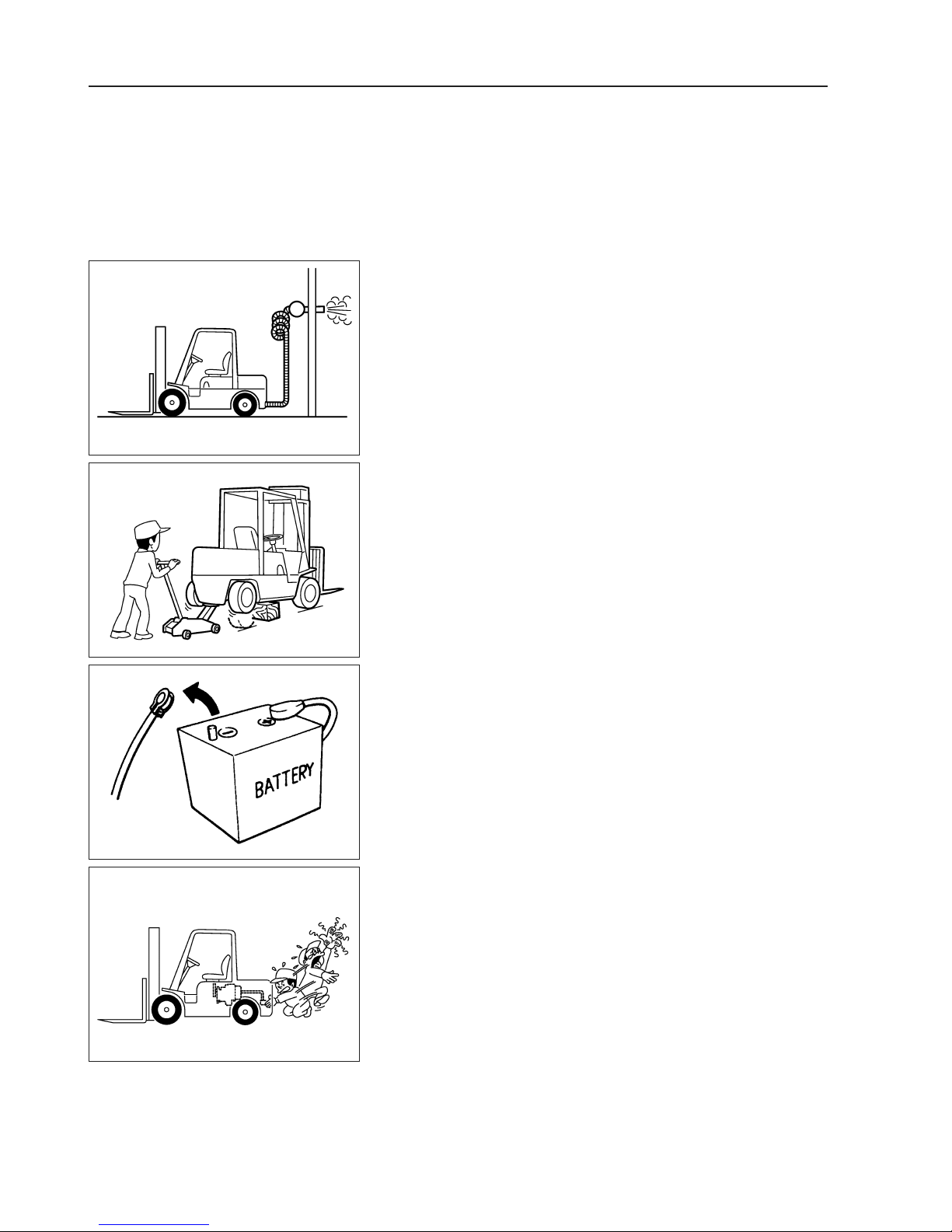
• Do not run the engine in a place which has no exhaust ducts
and which is poorly ventilated.
• Ventilate the workplace well and do not place a combustible
thing there. Take extreme care when handling a combustible
thing or a hazardous material such as gasoline.
• Dispose of the replaced oil, parts washing oil, etc. according to
laws.
• When working on parts which become hot, rotary parts, or
sliding parts, take care not to burn or injure yourself.
• When working in a pit or a closed place, ventilate it to discharge
EGM0043
harmful materials in advance.
• Do not work on the vehicle jacked up. When working on it,
support it by the specified parts on wood blocks, etc.
• When lifting up the vehicle, support it by the specified parts and
apply a safety device.
• When removing a heavy part such as the engine, vehicle body,
etc. take care not to drop it by unbalancing it.
• Do not smoke while maintaining the vehicle.
• When maintaining the vehicle, take off rings and necklace to
prevent a short circuit in the electrical system.
EGM0044
EGM0045
EGM0046
• Before starting repair which does not need the battery power,
turn the key switch OFF and disconnect the negative (–)
terminal of the battery.
• Take care not to touch the hot metal parts just after stopping the
engine. While the engine is still hot, do not remove the radiator
cap or another part of the coolant system.
• Use the specified proper common tools or special tools for safe
and efficient repair.
EG-2
Page 3

PRECAUTIONS FOR SAFETY AND QUALITY
Correct Work
• Grasp the contents of each trouble, and then troubleshoot and
work efficiently.
• When removing and disassembling parts, check their normal
assembly condition in advance. Make match marks on places
which do not affect the function, if necessary.
• If an oil seal, gasket, packing, O-ring, lock washer, cotter pin,
self-lock nut, etc. are removed, replace them according to the
directions in their sections (Parts which must not be reused).
• When a tapered roller bearing or a needle roller bearing needs
to be replaced, replace its inner race and outer race as a set.
• Arrange the removed parts in order so that they will not be
mixed up.
• Before checking or assembling the disassembled parts, clean
them.
• When replacing a part, install a NISSAN genuine part.
• Use the specified oil, grease, sealant, etc.
• Before removing a pressurized pipe, hose, etc., release the
pressure.
• After repairing the fuel, oil, coolant, exhaust, or vacuum system,
check it for leakage securely.
Precautions for Radio Equipment Installation
Check the following when installing a commercial/ham radio or
mobile phone. If mounting position is not chosen carefully, the unit
may interfere with the electronic control system.
• Separate the antenna as far from the ECM as possible.
• Route an antenna feeder line at least 20 cm (7.87 in) apart from
the control unit harness.
• Adjust an antenna and feeder line to eliminate radio wave
interference.
EG-3
Page 4

HOW TO READ THIS MANUAL
HOW TO READ THIS MANUAL
Outline
This chapter explains how to read the procedures of "removal,
disassembly, assembly, inspection, and adjustment" and "troubleshooting".
Definition of Terms
CAUTION:
• An item or a work procedure, neglect of which can cause a
death or a serious injury if neglected.
• An item or a work procedure to be observed especially
among those, neglect of which can cause an injury, an
accident, or a damage of the vehicle or component parts.
Reference : Supplementary explanation for the ease of work.
Standard value : Permissible deviation of a value at inspection or
adjustment.
Limit value : The maximum or minimum which a value must not
exceed at inspection or adjustment.
Definition of Units
In this manual, tightening torque, pressure, etc. are indicated by the
"SI unit" (International unit) first, then by the "metric unit) in { }.
Example) Tightening torque: 59 - 78 Nm {6.0 - 8.0 kgf•m}
SI unit {Metric unit}
CONVERSION OF MAJOR UNITS
Quantity SI unit Conventional unit Coefficient of conversion into SI
Acceleration
Torque and moment Nm kgf•m 9.80665
Force N kgf 9.80665
Pressure MPa
Power/Power efficiency kW PS 0.735499
Vol um e
Spring constant N/mm kgf/mm 9.80665
Fuel consumption g/kW•h(*1) g/PS•h 1.3596
2
m/s
kPa mmHg 0.133322
W kcal/h 1.16279
3
cm
G 9.80665
2
kgf/cm
cc 1
*1. Conventional unit may be used in SI.
0.09809665
EG-4
Page 5
HOW TO READ THIS MANUAL
Description
CAUTION : At the beginning of each section, the precautions
exclusive to the section are described.
Preparation: At the beginning of each section and during the trouble
diagnosis items, the SSTs, gauges, and other tools to
be prepared before operation are described. Some
commercial service tools, assumed to be available in
any workshop, are omitted.
Description : To perform correct operations, operational procedures,
notes, SSTs, and other service information are
described.
CAUTION : Descriptions of visual inspections and cleaning of
removed parts are generally omitted. Please
remember that actual operations require these
processes.
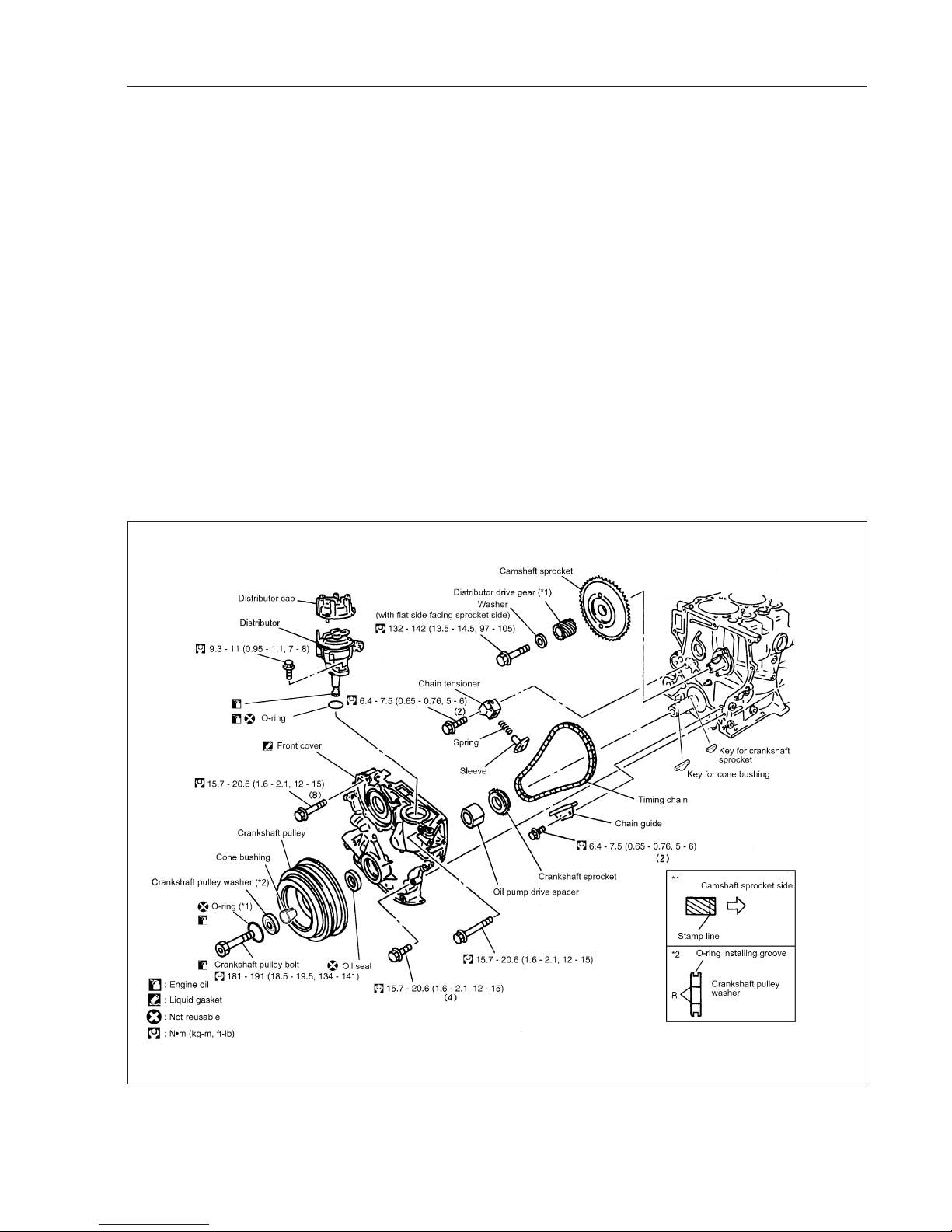
Component Parts Location
The "Component Parts Location" diagram (refer to the figure)
includes information for removal, installation, disassembly, and
assembly (tightening torque, grease points, non-reusable parts) as
well as other information important for repair work.
EGM0097
EG-5
Page 6
HOW TO READ THIS MANUAL
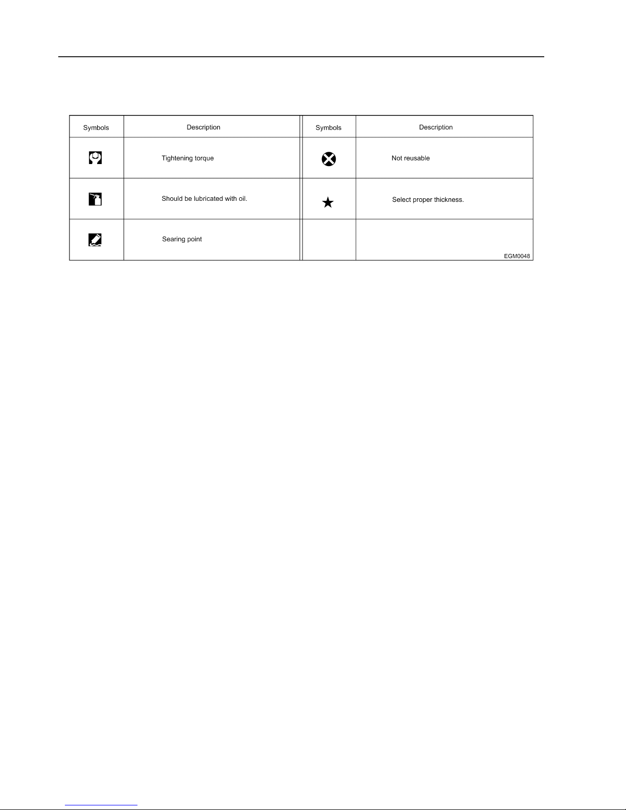
Component Parts Location (Cont'd)
COMPONENT SYMBOLS
EG-6
Page 7

TROUBLE DIAGNOSIS
TROUBLE DIAGNOSIS
ECM Trouble Diagnosis
CAUTION:
• The following trouble diagnosis procedures are designed
to identify the trouble causes efficiently. When performing
diagnoses, carefully observe the following instructions.
• Before starting a trouble diagnosis, carefully read and
understand the contents in "Basic Inspection", "Diagnosis
Chart by Symptom" and "Trouble Diagnosis Flowchart".
• After the repair work, always verify that the trouble is
eliminated.
• For the locations of the parts and harness connectors,
refer to "Component Parts Location" in the relevant
section.
• To perform a simple inspection, utilize the circuit diagrams.
To inspect the circuit for continuity in details including the
sub-harnesses, identify the relevant connectors and
harness layouts referring to the "Wiring Diagrams".
• Before inspecting a circuit for continuity, always turn the
ignition switch to OFF.
• Before measuring voltage at a connector, always measure
the battery voltage.
• After finishing diagnoses or inspections, always ensure
that all removed harness connectors are reconnected
correctly.
EG-7
Page 8
TROUBLE DIAGNOSIS
ECM Trouble Diagnosis (Cont'd)
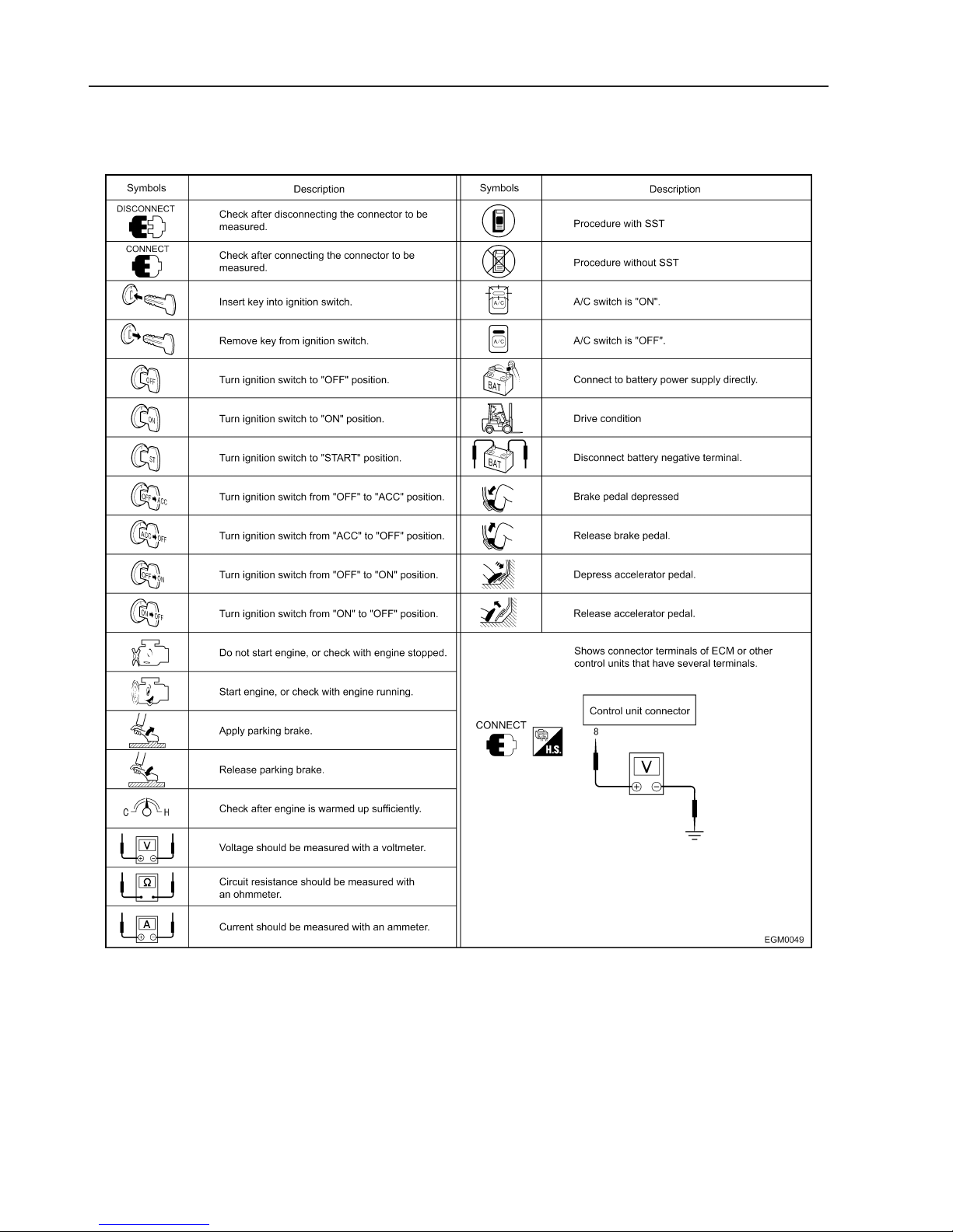
SYMBOLS
EG-8
Page 9

TROUBLE DIAGNOSIS
ECM Trouble Diagnosis (Cont'd)
SYMBOLS FOR HARNESS CONNECTOR
FEMALE CONNECTOR
• When a harness connector is viewed from A (terminal side), the
outer frame of the connector symbol is indicated with a single
line. In addition, the direction indicator shows "TS" (Terminal
Side) in description type font.
EGM0050
• When a harness connector is viewed from B (harness side), the
outer frame of the connector symbol is indicated with double
lines. In addition, the direction indicator shows "HS" (Harness
Side) in description type font.
• Terminal assignments of a connector viewed from A and B are
mirror images, indicating just as they are seen.
EGM0051
EGM0052
MALE CONNECTOR
The illustration method is the same as that for a female connector,
the black guide box, however, indicates a male connector (the white
guide box a female connector).
SINGLE UNIT (CONTROL UNIT)
A single control unit is viewed only from A, and the illustration is as
shown in the figure.
EGM0053
EG-9
Page 10

TROUBLE DIAGNOSIS
ECM Abbreviations List
Abbreviations Description Abbreviations Description
A/C Air conditioner INT Intake
A/T Automatic transmission LH Left
ALT Alternator LED Light emitting diode
ASSY Assembly LLC Long-life coolant
BAT Battery M/T Manual transmission
C/P Crankshaft pulley OHV Overhead valve
C/U Control unit OS Oversize
Cyl Cylinder P/S Power steering
ENG Engine PTO Power take-off
EXH Exhaust RH Right
F/L Fusible link RR Rear
FR Front TAS Throttle adjust screw
I/P Idler pulley Tr Transistor
IGN Ignition US Undersize
EG-10
Page 11

ECM GENERAL SERVICE INFORMATION
ECM GENERAL SERVICE INFORMATION
Connector Terminal Inspection
CONNECTOR INSPECTION PROCEDURE
In circuit inspection, inappropriate connector probing will cause
connector damages and/or poor connection. The probes provided
with the circuit tester may be too large to probe connector terminals
without damaging them. Always use alligator clips and "T" pins
according to following the procedure.
INSPECTION FROM HARNESS SIDE
For a standard connector without any waterproofing, use "T" pins
from the harness side.
CAUTION:
• For a connector with a rear cover, such as ECM
connectors, remove the rear cover before the inspection.
• For a waterproof connector, do not probe the terminals
from the harness side. Doing so may damage the seal.
EGM0054
INSPECTION FROM TERMINAL SIDE
1. Female terminal
• Female connector terminals have a small notch difference
inside. Insert a "T" pin along the step to inspect.
EGM0055
EGM0056
CAUTION:
Do not insert any objects to a female connector terminal other
than the corresponding male connector terminal.
• In case of a female connector terminal without any notches,
remove the retainer before probing.
EG-11
Page 12

ECM GENERAL SERVICE INFORMATION
Connector Terminal Inspection (Cont'd)
2. Male terminal
For a male connector terminal, apply a "T" pin to the surface of the
terminal.
CAUTION:
Do not bend terminals.
EGM0057
Inspection for Electrical System
DESCRIPTION
• If the malfunction can be traced directly to the electrical system,
first check for items such as burned-out fuses and fusible links,
broken wires or loose connectors, pulled-out terminals, and
improper connections.
• If a fuse or a fusible link is blown out, determine the possible
cause and restore it. Always replace it with a new fuse or fusible
link of the specified capacity.
• When removing a connector, do not apply excessive force to the
main body by grasping and twisting.
• Do not pull a connector off by tugging on the harness.
• For a lock-type connector, disengage its lock first, then
disconnect the connector by holding the main body of the
connector.
EGM0058
EGM0059
• Before connecting a connector, check terminals for bends or
breakage. Connect it securely.
• For a lock-type connector, press it until its lock is securely
engaged.
• When installing parts, prevent harnesses from being snagged
or overextended.
EG-12
Page 13

ECM GENERAL SERVICE INFORMATION
Control Unit and Electronic Component
PRECAUTIONS
• Never reverse polarity of battery terminals.
• Install only parts specified for each model.
• Before replacing a control unit, check input and output signals
to/from the control unit, and component functions.
• When disconnecting a connector, do not twist or apply
excessive force.
• For a bolt-type connector, loosen the bolt first, then hold the
main body of the connector to disconnect.
• Before connecting a connector, check terminals for bends or
breakage. Connect it securely. For a bolt-type connector, screw
in the bolt until the colored lug is flush with the surface to be
sure it is securely connected.
• Do not drop, hit, or subject control units to impact.
• Be sure to protect control units from condensation caused by a
sudden shift in temperature, or from raindrops or splashes. If
any water drops adhere to the unit, dry it well prior to
installation.
• Be sure to protect control unit connectors from oil.
• Avoid cleaning control units with benzine.
• Do not open a top or bottom cover on a control unit.
EGM0062
EGM0063
• When using a circuit tester, ensure the appropriate distance
between test probes. A longer distance is recommended,
because if the distance is too short, it may cause contact of the
test probes, resulting in a short circuit. A short circuit allows
battery voltage to be applied directly to the control unit, resulting
in damage to its internal power transistors.
• Use the specified check adapter to check input and output
signals to/from control units.
EG-13
Page 14

ECM GENERAL SERVICE INFORMATION
SST
DESCRIPTION
SST is a small, lightweight handheld tester. When connected to the
vehicle-side data link connector, it communicates with control units
installed on the vehicle and performs a variety of diagnostic tests.
FUNCTION AND APPLIED SYSTEM
Items Function
WORK SUPPORT Sends command to control unit to set status suitable for inspection and service.
FUNCTION SYSTEM Checks each system as ECM basic inspection.
SELF-DIAG RESULTS Receives self-diagnostic results from control unit and indicates DTCs and number of occurrences.
SELF-DIAG RESULTS
[MEMORY]
DATA MONITOR Receives input/output signals from control unit and indicates and stores them to facilitate locating cause of
DATA MONITOR [SPEC]
Active test Sends command to control unit to change output signals and check operation of output system.
DTC RECORD DISPLAY Indicates self-diagnostic results stored in ECM prior to the most recent "ERASE MEMORY".
Control unit part No. Displays control unit part number.
Control unit identification No. Displays control unit identification number.
DTCs (Diagnostic Trouble Codes) recorded in control unit's memory are displayed.
malfunctions.
Diagnostic systems Engine
WORK SUPPORT {
SELF-DIAG RESULTS {
SELF-DIAG RESULTS [MEMORY]
DATA MONITOR {
DATA MONITOR [SPEC] {
Active test {
DTC RECORD DISPLAY
Control unit part No. {
Control unit identification No.
EG-14
Page 15

PRECAUTIONS FOR WORK
PRECAUTIONS FOR WORK
Precautions for Draining Coolant
Drain the coolant after its temperature lowers sufficiently.
Precautions for Separating Fuel Piping
• Work in a place where there is nothing to start a fire.
• Release the fuel pressure in advance.
• After separating the fuel piping, plug it to prevent the fuel from
flowing out.
Precautions for Removal and Disassembly
• If specified, use correct special tools and pay attention. Do not
apply an excessive force.
• Take extreme care not to lower the accuracy of the mating
faces, sliding faces, etc.
• If necessary, cover the openings with tapes, etc. to prevent
foreign matter from entering the engine.
• Make marks on the removed parts and arrange them for secure
troubleshooting and assembly.
• As a rule, loosen the bolts and nuts from outside in the diagonal
direction. If the loosening order is specified, observe it.
Precautions for Checking, Repairing, and
Replacing Parts
Before repairing or replacing parts, check them sufficiently according
to the check procedure. Check the new parts similarly and replace
them if necessary.
Precautions for Assembling and Installing
Parts
• When tightening the bolts and nuts, be sure to use torque
wrenches.
• As a rule, tighten the bolts and nuts from inside to outside in the
diagonal direction in 2 – 3 times. If the tightening order is
specified, observe it.
• Replace the gaskets, packings, oil seal, and O-rings with new
ones.
• Clean each part and dry it by blowing compressed air against it.
In particular, take care that the oil passages and coolant
passages will not be clogged.
• Take care not to damage the sliding surfaces and mating faces,
and remove all dirt, lint, etc. from them. Apply sufficient oil to the
sliding surface before assembling.
• If the coolant is drained, bleed air from the coolant system.
• After repairing, run the engine at high speed and check for
leakage of the coolant, fuel, oil, grease, and exhaust gas.
EG-15
Page 16

PRECAUTIONS FOR WORK
Precautions for Using Power Tools
Use power tools such as an air runner for disassembly only. Do not
use them for assembly.
Precautions for Applying Gasket Sealant
SEPARATION OF PARTS COATED WITH GASKET
SEALANT
• After removing the mounting bolts and mounting nuts, cut and
remove the gasket sealant with seal cutter (special tool KV101-
11100) according tothe following procedure.
[1] Drive in the seal cutter in the direction of the arrow.
[2] Slide the seal cutter in the direction of the arrow.
[3] Slide the seal cutter in the direction of the arrow.
CAUTION:
• Take care not to damage the mating faces.
• If it is difficult to use the seal cutter, remove the gasket
EGM0066
sealant by hitting it lightly with a plastic hammer.
CAUTION:
If it is obliged to use a flat-head screwdriver, take extreme care
not to damage the mating faces.
EGM0067
EGM0068
PROCEDURE FOR APPLYING GASKET SEALANT
1. Remove the old gasket sealant sticking to the mating faces with
scraper.
• Remove all the gasket sealant from the grooves, mounting
bolts, and bolt holes, too.
2. Wipe the mating faces with isoparaffin, etc. to remove water, oil,
grease, and foreign matter.
3. Install the genuine gasket sealant to tube presser (common
tool).
4. Apply the gasket sealant to the specified parts and dimensions
without breaking it.
• Apply the gasket sealant to the grooves, too, if specified so.
• As a rule, apply the gasket sealant to the inside of the bolt
holes. The outside of the bolt holes may need to be coated
with the gasket sealant, however. Accordingly, refer to the
manual without fail.
• Install the parts within 5 minutes after applying the gasket
sealant.
• Wipe off the projected gasket sealant immediately.
• Do not retighten the bolts after installing the parts.
• After installing the parts, wait at least 30 minutes before
supplying engine oil or coolant.
CAUTION:
If a direction is given in the manual, observe it.
EG-16
Page 17

PRECAUTIONS FOR WORK
Parts Which Need to be Tightened by Angle
Tightening Method
• Use angle wrenches (special tools) to tighten the following
parts.
• Cylinder head bolt
Check that the cylinder head, cylinder block mounting face, and
cylinder head gasket are free from oil and dirt, and then coat the
threads and stem of the cylinder head bolt and tighten it.
EG-17
Page 18

Seal cutter
KV1011 11100
Ring gear stopper
KVl101 056S0
1 Adapter
KV101 05630
2 Stopper plate
KV101 05610
Oil seal drift
KV101 04900
Angle wrench
KV101 12100
PREPARATION
PREPARATION
Special Service Tools
Special Service Tools (Cont'd)
Description Application Remarks
Removing parts attached with
liquid gasket
EGM0069
Removing and installing
crankshaft pulley
EGM0070
Installing front oil seal
EGM0071
Checking tightening angle
1. Valve spring compressor
KV101 09210
2. Adapter
KV101 11200
Valve oil seal puller
KV101 07901
Valve oil seal drift
KV101 13000
Already established
EGM0072
Removing and installing valve
collet
EGM0073
Removing valve oil seal
EGM0074
Installing valve oil seal
EGM0075
EG-18
Page 19

Engine stand assembly
ST0501 S000
Engine attachment
KV101 06500
Engine sub-attachment
KV111 04800
Camshaft bushing tool set
KV111 045S0
1. Bar
KV111 04510
2. Guide plate
KV111 04520
3. Adapter
KV111 04530
4. Drift
ST1524 3000
Pulley puller
KV111 03000
PREPARATION
Special Service Tools (Cont'd)
Description Application Remarks
Overhauling engine
EGM0076
EGM0077
Already established
EGM0078
Removing and installing camshaft
bushing
EGM0079
Removing crankshaft pulley. Already established
Oil filter wrench
KV101 15801
EGI fuel pressure indicator
ST1959 0000
EGM0080
Removing oil filter Already established
EGM0081
For measuring fuel pressure
gauge
EGM0082
EG-19
Page 20

Heated oxygen sensor wrench
KV101 13700
Maintenance tool
1. DIAGNOSIS KIT
SKVEE GY010
2. SOFT WARE
SKVEE GY100
Check adapter V
EG1755 0000
(for SMJ 150-pin connector)
Harness adapter
EG1755 0200
(150-pin to 121-pin conversion adapter)
PREPARATION
Special Service Tools (Cont'd)
Description Application Remarks
Removing and installing heated
oxygen sensor
EGM0083
For system inspection and
diagnosis
For control unit input/output signal
inspection
EGM0084
For molding coil
Adapter harness
EG101 17500
EGM0085
Checking engine speed
EGM0086
Service Parts
Piston oversize
0.5 mm (0.020 in) OS [0.5 mm (0.020 in) oversize]
1.0 mm (0.039 in) OS [1.0 mm (0.039 in) oversize]
Main bearing undersize
Unit: mm (in)
Size Thickness
STD 2.000 (0.0787)
US 0.25 (0.0098) 2.125 (0.0837)
US 0.50 (0.0197) 2.250 (0.0886)
US 0.75 (0.0295) 2.375 (0.0935)
US 1.00 (0.0394) 2.500 (0.0984)
EG-20
Page 21

Refer to the following notes for values in ( ).
Engine system inspection (except LPG fuel systems)
No. Inspection items
1 Intake/exhaust valve clearance
Electronic controls
2 Engine drive belt tension Electronic
3 Engine oil Electronic
4 Oil filter Electronic
5 Engine coolant Electronic
6 Air cleaner element Electronic
7 Ignition timing Electronic
8 Spark plug Electronic
9 Distributor Electronic
10 PCV valve Electronic
11 PCV hose Electronic
Applicable
control
system
Electronic
controls
controls
controls
controls
controls
controls
controls
controls
controls
controls
controls
SERVICE DATA
SERVICE DATA
Periodical Inspection
To maintain the initial performance of the KOMATSU FORKLIFT,
make sure to perform appropriate maintenance and service work.
PERFORM INSPECTION
Make sure to perform the periodical inspections at the appropriate
times, according to the month basis or the operating hour basis,
whichever comes first.
Months of
use
Operation
hours
(x 100 hours)
(1) RRRRRRRRRRRR...R
(1) R R R R R ... R
(1) I I I I ... I
123456789101112...18
2 4 6 8 1012141618202224 ... 36
AAAAA...A
IIIIIIIIIIII...I
R...
CCCCCRCCCCCR...R
AAAAAAAAAAAA...A
IIIIIIIIIIII...R
C...
IIII...I
EG-21
Page 22

SERVICE DATA
Periodical Inspection (Cont'd)
No. Engine system inspection (LPG models)
1 Gas leakage from piping and piping
joints
2 Damage to piping and piping joints Electronic
3 Tar in vaporizer Electronic
4 Injection nozzle Electronic
5 LPG filter Electronic
CAUTION:
• If the vehicle is being used in dusty and dirty environments, the maintenance work should be performed
more frequently.
• After replacing the LPG tank, apply soapsuds to the piping joints to check for any gas leakage.
Meanings of symbols: I = Inspection. Repair or replace if necessary.
R = Replacement
A = Adjustment
C = Cleaning
D = Draining
T = Tightening (Retightening)
Electronic
controls
controls
controls
controls
controls
(2) IIIIIIIIIIII ...I
IIIIIIIIIIII ...I
DDDDDDDDDDDD ...D
IIIII...I
CCCR...C
EG-22
Page 23

SERVICE DATA
Standard, Repair Limit
Fuel in use Gasoline specification Lead-free regular gasoline with an octane value of 91 or more
LPG specification 20-100P
Engine weight (without water, with oil) kg (lb) Approx. GAS, LPG:301’, DUAL:302’
Firing order 1 - 5 - 3 - 6 - 2 - 4
Compression pressure
kPa (bar, kgf/cm
Distortion limit mm (in) Intake manifold 0.2 (0.008)
Engine oil amount l (Imp qt)
(SL class)
Spark plug Manufacturer/type/gap mm (in) NGK/BPR4ES-D/0.8 - 0.9 (0.031 - 0.035)
Resistance on high-tension cable (k:) #1: Approx. 2.7 #2: Approx. 2.8 #3: Approx. 4
Ignition advance device Electronically controlled ignition advance
Onboard idle speed (rpm) 750 r 50
Onboard idling pace speed (When feedback control is stopped) (rpm) 750
Density of CO at idle speed/Density of HC at idle speed (%/ppm) 0.1 or less/50 or less
Ignition timing (When feedback control is stopped) (BTDCq/rpm) 10 r 2/750
Valve clearance mm (in) INT/EXH Hot 0.35 (0.0138)/0.35 (0.0138)
Thermostat opening valve temperature (Start - Full open) qC (qF) 82 - 95 (180 - 203)
Engine drive belt deflection New belt After adjustment Limit
[Measured by pressing
with 98 N (10 kg, 22 lb)] mm (in)
2
, psi)/rpm
Standard 1,187 (11.87, 12.1, 172)/200
Repair limit 892 (8.92, 9.1, 129)/200
Difference limit among cylinders 98 (0.98, 1.0, 14)/200
Exhaust manifold
Cylinder head 0.2 (0.008)
Cylinder block 0.1 (0.004)
When replacing oil only Approx. 8.3 (7-1/4)
When replacing oil and filter Approx. 8.6 (6-5/8)
#4: Approx. 5 #5: Approx. 5.2 #6: Approx. 6.1
Alternator belt/Fan belt 10 - 12
(0.39 - 0.47)
0.3 (0.012)
13 - 15
(0.51 - 0.59)
16 (0.63)
EGM0098
EG-23
Page 24

SERVICE DATA
Tightening Torque
STANDARD BOLT TIGHTENING TORQUE
<Hexagon head> <No lubrication> Unit: N•m (kg-m, ft-lb)
N•m (kg-m, in-lb)*
Normal size
d
M3 0.5 0.6
M3.5 0.6 1.0
M4 0.7 1.5
M5 0.8 2.9
M6 1.0 5.0
M8 1.25 12.7
M10 1.5 24.5
M12 1.75 42.2
M14 1.5 73.6
M16 1.5 108
M18 1.5 167
M20 1.5 226
M22 1.5 304
Pitch
P
1.0 13.7
1.25 25.5
1.25 46.1
Non-flanged
bolt
(0.06, 5)*
(0.10, 9)*
(0.15, 13)*
(0.30, 26)*
(0.51, 44)*
(1.3, 9.4)
(1.4, 10)
(2.5, 18)
(2.6, 19)
(4.3, 31)
(4.7, 34)
(7.5, 54)
(11, 80)
(17, 123)
(23, 166)
(31, 224)
4T 7T 9T
Flanged bolt Non-flanged bolt Flanged bolt
0.7
(0.07, 6)*
1.2
(0.12, 10)*
1.7
(0.17, 15)*
3.5
(0.36, 31)*
6.0
(0.61, 53)*
14.7
(1.5, 10.8)
15.7
(1.6, 12)
29.4
(3.0, 22)
30.4
(3.1, 22)
51
(5.2, 38)
55.9
(5.7, 41)
87.3
(8.9, 64)
137
(14, 101)
196
(20, 145)
275
(28, 203)
363
(37, 268)
1.1
(0.11, 10)*
1.7
(0.17, 15)*
2.5
(0.25, 22)*
5.0
(0.51, 44)*
8.4
(0.86, 75)*
20.6
(2.1, 15)
21.6
(2.2, 16)
41.2
(4.2, 30)
43.1
(4.4, 32)
70.6
(7.2, 52)
77.5
(7.9, 57)
127
(13, 94)
186
(19, 137)
275
(28, 203)
382
(39, 282)
510
(52, 376)
1.3
(0.13, 11)*
2.1
(0.21, 18)*
2.9
(0.30, 26)*
5.9
(0.6, 52)*
10
(1.0, 87)*
24.5
(2.5, 18)
26.5
(2.7, 20)
49
5, 36)
(
51
(5.2, 38)
84.3
(8.6, 62)
92.2
(9.4, 68)
147
(15, 108)
226
(23, 166)
324
(33, 239)
451
(46, 333)
608
(62, 448)
Non-flanged
bolt
1.6
(0.16, 14)*
2.5
(0.25, 22)*
3.5
(0.36, 31)*
7.2
(0.73, 63)*
11.8
(1.2, 8.7)
29.4
(3.0, 22)
31.4
(3.2, 23)
58.8
(6.0, 43)
61.8
(6.3, 46)
98.1
(10, 72)
108
(11, 80)
177
(18, 130)
265
(27, 195)
392
(40, 289)
549
(56, 405)
736
(75, 542)
Flanged bolt
1.9
(0.19, 16)*
2.8
(0.29, 25)*
4.2
(0.43, 37)*
8.5
(0.87, 76)*
14.7
(1.5, 10.8)
35.3
(3.6, 26)
37.3
(3.8, 27)
69.6
(7
.1, 51)
73.6
(7.5, 54)
118
(12, 87)
137
(14, 101)
206
(21, 152)
324
(33, 239)
471
(48, 34)
657
(67, 485)
883
(90, 651)
CAUTION:
• Except special parts.
• The bolt applicable to the list has the following number embossed on the head.
Model Number
4T ... 4 or none
7T ... 7
9T ... 9
CAUTION FOR USE OF POWER TOOLS
Do not use any power tools (e.g. air ratchet, impact wrench) to
tighten the bolts and nuts. Use these tools only for loosening the
bolts and nuts. However, do not use power tools in any event and for
any purposes on the parts subject to heat (catalyst, muffler, and
other exhaust parts) and the tapping screws. These parts may also
be damaged when loosened with a power tool.
EG-24
Page 25

SERVICE DATA
Tightening Torque (Cont'd)
MAIN TIGHTENING TORQUE
* : Parts with tightening sequence
1) - :Tighten separately in several turns.
Unit :N•m (kg-m, ft-lb)
N•m (kg-m, in-lb)*
Parts name or location Tightening torque
Adjusting screw Lock nut 16 - 22 (1.6 - 2.2, 12 - 16)
AlternatorAdjusting bar side
Bracket side
Oil pan drain plug 54 - 59 (5.5 - 6.0, 40 - 43)
Spark plug 20 - 29 (2.04 - 2.96, 14 - 22)
* Intake manifold 15.7 - 18.6 (1.6 - 1.9, 12 - 14)
* Air horn 20.6 - 26.5 (2.1 - 2.7, 16 - 27)
Exhaust manifold cover 6.37 - 7.45 (0.65 - 0.76, 56 - 66)*
* Exhaust manifold 27 - 31 (2.8 - 3.2, 20 - 23)
Exhaust manifold connector 59 - 78 (6.0 - 8.0, 43 - 58)
* Oil pan [M6]
[M8]
Oil strainer 16 - 19 (1.6 - 1.9, 12 - 14)
* Rocker cover 1.0 - 2.9 (0.1 - 0.3, 9 - 26)*
Rocker shaft bracket 15.6 - 21.6 (1.6 - 2.2, 12 - 16)
* Cylinder head bolt 1) 29.4 (3, 22)
Cylinder head additional bolt 6.4 - 7.5 (0.65 - 0.76, 56 - 66)*
Crankshaft pulley 181 - 191 (18.5 - 19.5, 134 - 141)
* Front cover 15.7 - 20.6 (1.6 - 2.1, 12 - 15)
Camshaft sprocket 132.3 - 142.1 (13.5 - 14.5, 98 - 105)
Chain tensioner 5.6 - 8.4 (0.57 - 0.86, 49.5 - 74.7)
Distributor 9.35 - 11 (0.95 - 1.1, 82 - 95)*
Camshaft locating plate 5.6 - 8.4 (0.57 - 0.86, 49.5 - 74.7)
* Flywheel 146 - 167 (15 - 17, 108 - 123)
* Main bearing cap 162 - 172 (16.5 - 17.5, 119 - 127)
Connecting rod nut 1) 38 - 40 (3.9 - 4.1, 28 - 30)
Engine coolant drain plug 34 - 44 (3.5 - 4.5, 25 - 33)
Water pump 15.7 - 18.6 (1.6 - 1.9, 12 - 14)
Engine coolant temperature sensor 20 - 29 (2.0 - 3.0, 14 - 22)
PCV valve 20 - 29 (2.0 - 3.0, 14 - 22)
* Fuel tube 1) 9.3 - 20.6 (0.9 - 2.1, 78 - 182)*
Starter motor 41.2 - 52 (4.2 - 5.3, 30 - 38)
Heated oxygen sensor 1 40 - 60 (4.1 - 6.1, 30 - 44)
17.5 - 23.7 (1.8 - 2.4, 13 - 17)
50.0 - 67.6 (5.1 - 6.9, 37 - 50)
6.3 - 8.3 (0.64 - 0.85, 56 - 74)*
15.7 - 20.6 (1.6 - 2.1, 12 - 15)
2) 61.7 (6.3, 46)
3) 0 (0, 0)
4) 29.4 (3, 22)
5) 69q - 74q(Angle tightening)
2) 40q - 45q(Angle tightening)
2) 20.6 - 26.5 (2.1 - 2.7, 15 - 20)
EG-25
 Loading...