

WEBM005500

WEBM005500
SK714-5 SK815-5 SK815-5 turbo
00-1

CONTENTS
CONTENTS
Page
10 STRUCTURE AND FUNCTION........................................................................................10-1
20 TESTING AND ADJUSTING.............................................................................................20-1
30 DISASSEMBLY AND ASSEMBLY..................................................................................30-1
40 MAINTENANCE STANDARD...........................................................................................40-1
00-2
SK714-5 SK815-5 SK815-5 turbo

The affected pages are indicated by the use of the
following marks. It is requested that necessary actions be taken to these pages according to table below.
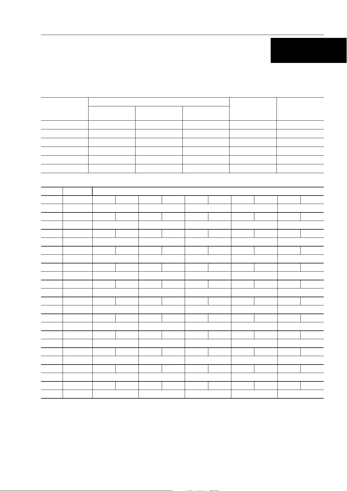
REVISED PAGES
Mark Indication Action required
❍
Page to be newly Add
Mark Page
00-1
00-2
00-2-1
00-2-2
00-3
00-4
00-5
00-6
00-7
00-8
00-9
00-10
00-11
00-12
00-13
00-14
00-15
00-16
00-17
00-18
00-19
00-20
00-21
00-22
10-1
10-2
10-3
10-4
10-5
10-6
10-7
10-8
10-9
10-10
10-11
10-12
10-13
10-14
10-15
10-16
Time of
revision
Mark Page
10-17
10-18
10-19
10-20
10-21
10-22
10-23
10-24
10-25
10-26
10-27
10-28
10-29
10-30
10-31
10-32
10-33
10-34
10-35
10-36
10-37
10-38
10-39
10-40
10-41
10-42
10-43
10-44
10-45
10-46
10-47
10-48
10-49
10-50
10-51
10-52
10-53
10-54
10-55
10-56
10-57
LIST OF REVISED PAGES
Time of
revision
Mark Page
10-58
10-59
10-60
10-61
10-62
10-63
10-64
10-65
10-66
10-67
10-68
10-69
10-70
10-71
10-72
10-73
10-74
10-75
10-76
10-77
10-78
10-79
10-80
10-81
10-82
10-83
10-84
10-85
10-86
10-87
10-88
10-89
10-90
10-91
10-92
10-93
10-94
10-95
10-96
10-97
10-98
●
Page to be replaced Replace
( ) Page to b e delete Discar d
Pages having no marks are those previously revised or
made additions.
Time of
revision
Mark Page
10-99
10-100
10-101
10-102
10-103
10-104
10-105
Time of
revision
Mark Page
20-32
20-34
20-35
20-36
20-37
20-38
20-39
Time of
revision
10-106
30-1
20-1
20-2
20-3
20-4
20-5
20-6
20-7
20-8
20-9
20-10
20-11
20-12
20-13
20-14
20-15
20-16
20-17
20-18
20-19
20-20
20-21
20-22
20-23
20-24
20-25
20-26
20-27
20-28
20-29
20-30
20-31
20-32
30-2
30-3
30-4
30-5
30-6
30-7
30-8
30-9
30-10
30-11
30-12
30-13
30-14
30-15
30-16
30-17
30-18
30-19
30-20
30-21
30-22
30-23
30-24
30-25
30-26
30-27
30-28
30-29
30-30
30-31
30-32
30-33
SK714-5 SK815-5 SK815-5 turbo
00-2-1

REVISED PAGES
Mark Page
30-34
30-35
30-36
30-37
30-38
30-39
30-40
30-41
30-42
30-43
30-44
30-45
30-46
30-47
30-48
30-49
30-50
30-51
30-52
30-53
30-54
30-55
30-56
30-57
30-58
30-59
30-60
30-61
30-62
Time of
revision
Mark Page
Time of
revision
Mark Page
Time of
revision
Mark Page
Time of
revision
Mark Page
Time of
revision
40-1
40-2
40-3
40-4
40-5
40-6
40-7
40-8
40-9
40-10
40-11
40-12
40-13
40-14
40-15
40-16
40-17
40-18
40-19
40-20
40-21
40-22
00-2-2
SK714-5 SK815-5 SK815-5 turbo

IMPORTANT SAFETY NOTICE
Proper service and repair is extremely important for the safe operation of your machine.
The service and repair techniques recommended by Komatsu Utility and describe in this manual are both effective and safe methods of operation. Some of these operations require the use of tools specially designed
by Komatsu Utility for the purpose.
To prevent injury to workers, the symbols and are used to mark safety precautions in this manual.
The cautions accompanying these symbols should always be carefully followed. If any danger arises or may
possibly arise, first consider safety, and take necessary steps to face.
SAFETY
GENERAL PRECAUTIONS
Mistakes in operation extremely dangerous.
Read all the Operation and Maintenance Manual carefully BEFORE operating the machine.
1. Before carrying out any greasing or repairs, read all
the precautions written on the decals which are suck
on the machine.
2. When carrying out any operation, always wear safety shoes and helmet. Do not wear loose work
clothes, or clothes with buttons missing.
• Always wear safety glasses when hitting parts
with a hammer.
• Always wear safety glasses when grinding
parts with a grinder, etc.
3. If welding repairs are needed, always have a
trained, experienced welder carry out the work.
When carrying out welding work, always wear welding gloves, apron, glasses, cap and other clo thes
suited for welding work.
4. When carrying out any operation with two or more
workers, always agree on the operating procedure
before starting. Always inform your fellow workers
before starting any step of the operation. Before
starting work, hang UNDER REPAIR signs on the
controls in the operator’s compartment.
5. Keep all tools in good condition and learn the correct
way to use them.
6. Decide a place in the repair workshop to keep tools
and removed parts. Always keep the tools and parts
in their correct places. Always keep the work are a
clean and make sure that there is no dirt or oil on the
floor.
Smoke only in the areas provided for smoking. Never smoke while working.
PREPARATIONS FOR WORK
7. Before adding or making any repairs, park the machine on hard, level ground, and block the wheels to
prevent the machine from moving.
8. Before starting work, lower outrigger, bucket or any
other work equipment to the ground. If this is not
possible, use blocks to prevent the work equipment
from falling down. In addition, be sure to lock all the
control levers and hang warning sign on them.
9. When disassembling or assembling, support the
machine with blocks, jacks or stands before starting
work.
10. Remove all mud and oil from the steps or other places used to get on and off the machine. Always use
the handrails, ladders or steps when getting on or off
the machine.
Never jump on or off the machine.
If it is impossible to use the handrails, ladders or
steps, use a stand to provide safe footing.
PRECAUTIONS DURING WORK
11. When removing the oil filler cap, drain plug or hydraulic pressure measuring plugs, loosen them
slowly to prevent the oil from spurting out.
Before disconnecting or removing components of
the hydraulic circuit and engine cooling circuit, first
remove the pressure completely from the circuit.
12. The water and oil in the circuits are not hot when the
engine in stopped, so be careful not to get burned.
Wait for the oil water to cool before carrying out any
work on the cooling water circuits.
13. Before starting work, remove the leads from the battery. Always remove the lead from the negative ( – )
terminal first.
SAFETY
SK714-5 SK815-5 SK815-5 turbo
00-3

SAFETY
14. When raising heavy components, use a hoist or
crane. Check that the wire rope, chains and hooks
are free from damage.
Always use lifting equipment which has ample ca pacity. Install the lifting equipment at the correct
places.
Use a hoist or crane and operate slowly to prevent
the component from hitting any other part.
Do not work with any part still raised by the hoist or
crane.
15. When removing covers which are under internal
pressure or under pressure from a spring, always
leave two bolts in position on opposite sides. Slowly
release the pressure, then slowly loosen the bolts to
remove.
16. When removing components, be careful not to
break or damage the wiring.
Damage wiring may cause electrical fires.
17. When removing piping, stop the fuel or oil from spilling out. If any fuel or oil drips on to the floor, wipe it up
immediately.
Fuel or oil on the floor can cause you to slip, or can
even start fires.
18. As a general rule, do not use gasoline to wash parts.
In particular, use only the minimum of gasoline
when washing electrical parts.
19. Be sure to assemble all parts again in their original
places. Replace any damage parts with new parts.
When installing hoses and wires, be sure that they
will not be damaged by contact with other parts
when the machine is being operated.
20. When installing high pressure hoses, make sure
that they are not twisted. Damaged tubes are dangerous, so be extremely careful when installing
tubes for high pressure circuits. Also, check that
connecting parts are correctly tightened.
21. When assembling or installing parts, always use
specified tightening torques.
When installing the parts which vibrate violently or
rotate at high speed, be particulary careful to check
that they are correctly installed.
22. When aligning two holes, never insert your fingers
or hand.
23. When measuring hydraulic pressure, check that the
measuring tool is correctly assembled before taking
any measurement.
24. Take sure when removing or installing wheels.
00-4
SK714-5 SK815-5 SK815-5 turbo

FOREWORD
FOREWORD
This shop manual has been prepared as an aid to improve the quality of repairs by giving the operator an accurate
understanding of the product and by showing him the correct way to perform repairs and make judgements. Make sure
you understand the contents of this manual and use it to full effect at every opportunity.
This shop manual mainly contains the necessary technical information for operations performed in a service workshop.
The manual is divided into chapters on each main group of components; these chapters are further divided into the
following sections.
STRUCTURE AND FUNCTION
This section explains the structure and function of each component. It serves not only to give an u nderstanding
of the structure, but also serves as reference material for troubleshooting.
TESTING AND ADJUSTING
This sections explains checks to be made before and after performing repairs, as well as adjustments to be
made at completion of the checks and repairs.
Troubleshooting charts correlating «Problems» to «Causes» are also included in this section.
DISASSEMBLY AND ASSEMBLY
This section explains the order to be followed when removing, installing, disassembling or assembling each
component, as well as precautions to be taken for these operations.
MAINTENANCE STANDARD
This section gives the judgement standards when inspecting disassembled parts.
NOTE
The specifications contained in this shop manual are subject to change at any time and without any notice.
Contact your Komatsu Utility distributor for the latest information.
SK714-5 SK815-5 SK815-5 turbo
00-5
HOW TO READ THE SHOP MANUAL
HOW TO READ THE SHOP MANUAL
VOLUMES
Shop manual are issued as a guide to carry out repairs.
These various volumes are designed to avoid duplicating the same information.
DISTRIBUTION AND UPDATING
Any additions, amendments or other changes will be
sent to Komatsu Utility distributors.
Get the most up-to-date information before you start any
work.
FILING METHOD
1. See the page number on the bottom of the page.
File the pages in correct order.
2. Following examples show you how to read the page
number.
Example:
10
-
3
Item number (10. Structure and
Function)
Consecutive page number for each
item
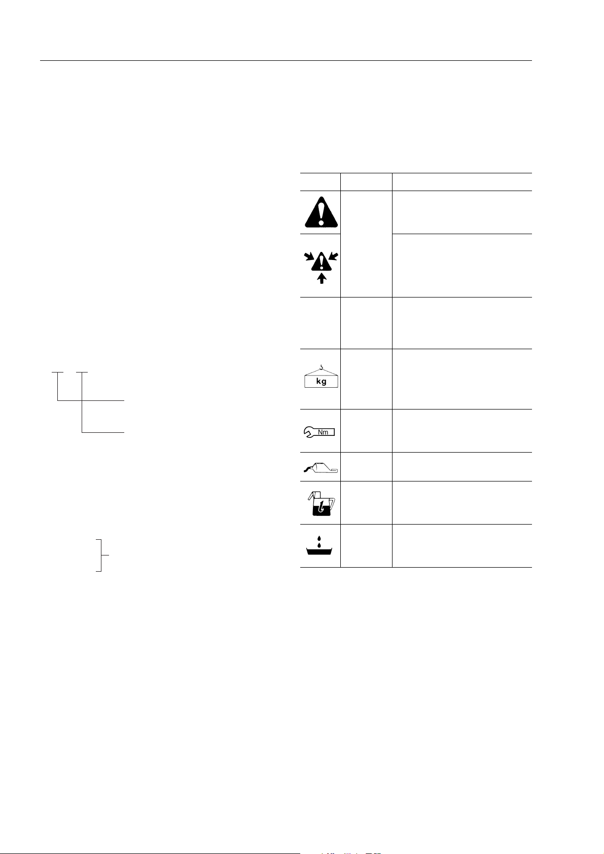
SYMBOLS
In order to make the shop manual greatly chelpful, important points about safety and q uality are marked with
the following symbols.
Symbol Item Remarks
Special safety precautions
are necessary when
performing the work.
★
Safety
Caution
Weight
Tightening
torque
Extra special safety precautions
are necessary when performing
the work because it is under internal pressure.
Special technical precautions or
other precautions for preserving
standards are necessary when
performing the work.
Weight of parts or systems.
Caution necessary when selecting hoisting wire, or when working posture is important, etc.
Parts that require special attention for the tightening torque during assembly.
3. Additional pages: additional pages are indicated by
a hyphen (–) and number after the page number.
Fle as in the example.
Example:
10-4
10-4-1
Added pages
10-4-2
10-5
REVISED EDITION MARK
(
➀ ➁ ➂ ....)
When a manual is revised, an edition mark is recorded
on the bottom outside corner of the pages.
REVISIONS
Revised pages are shown on the LIST OF REVISED
PAGES between the title page and SAFETY page.
Coat
Oil, water
Drain
Parts to be coated with adhesives and lubricants etc.
Places where oil, water or fuel
must be added, and their quantity.
Places where oil or water must
be drained, and quantity to be
drained.
00-6
SK714-5 SK815-5 SK815-5 turbo

HOISTING INSTRUCTIONS
Heavy parts (25 kg or more) must be lifted
with a hoist etc. In the
bly
section, every part weighing 25 kg or more is
clearly indicated with the symbol
1. If a part cannot be smoothly removed from the machine by hoisting, the following checks should be
made:
• Check for removal of all bolts fastening the part
to the relative parts.
• Check for any part causing interference with
the part to be removed.
2. Wire ropes
1) Use adequate ropes depending on the weight of
parts to be hoisted, referring to the table below:
(Standard «S» or «Z» twist ropes
without galvanizing)
Rope diameter (mm) Allowable load (tons)
10.0
11.2
12.5
14.0
16.0
18.0
Disassembly and Assem-
WIRE ROPES
1.0
1.4
1.6
2.2
2.8
3.6
HOISTING INSTRUCTIONS
Hooks have maximum strength at the middle portion.
3) Do not sling a heavy load with one rope alone, but
sling with two or more ropes symmetrically wound
on to the load.
Slinging with one rope may cause turning of the load
during hoisting, untwisting of the rope, or slipping of
the rope from its original winding position on the
load, which can cause dangerous accidents.
4) Do not sling a heavy load with ropes forming a wide
hanging angle from the hook.
When hoisting a load with two or more ropes, the
force subjected to each rope will increase with the
hanging angles.
The table below shows the va riation of a llowable
load (kg) when hoisting is made with two ropes,
each of which is allowed to sling up to 1000 kg vertically, at various handing angles.
When two ropes sling a load vertically, up to 2000 kg
of total weight can be suspended.
This weight becomes 1000 kg when two ropes
make a 120° hanging angle.
On the other hand, two ropes are subjected to an excessive force as large as 4000 kg if they sling a 2000
kg load at a lifting angle of 150°.
20.0
22.4
30.0
40.0
50.0
60.0
The allowable load value is estimated to be onesixth or one-seventh of the breaking strength of the
rope used.
2) Sling wire ropes from the middle portion of the hook.
Slinging near the edge of the hook may cause the
rope to slip off the hook during hoist
rious accident can result.
4.4
5.6
10.0
18.0
28.0
40.0
ing, and a se-
SK714-5 SK815-5 SK815-5 turbo
00-7

STANDARD TIGHTENING TORQUE
The following charts give the standard tightening torques of bolts and nuts.
Exceptions are given in section of «Disassembly and Assembly».
1. STANDARD TIGHTENING TORQUE OF BOLTS AND NUT
Width across flat
Thread
diameter of bolts
(mm)
Pitch of
bolts
(mm)
(mm)
kgmNmkgmNm
STANDARD TIGHTENING TORQUE
10
12
14
16
18
20
22
24
27
30
6
8
1
1.25
1.5
1.75
2
2
2.5
2.5
2.5
3
3
3.5
10
13
17
19
22
24
27
30
32
36
41
46
8
6
8
10
12
14
14
17
17
19
19
22
0.96
2.3
4.6
7.8
12.5
19.5
27
38
52
66
96±10
131
±0.1
±0.2
±0.5
±0.8
±1
±2
±3
±4
±6
±7
±14
9.5
23
45
77
122
191
262
372
511
644
945
1287
±1
±2
±4.9
±8
±13
±21
±28
±40
±57
±70
±100
±140
1.3
3.2
6.5
17.5
92
135
184
±0.15
±0.3
±0.6
11
27
37
53
73
±10
±1
±2
±3
±4
±6
±8
±15
±20
13.5
32.2
63
108
172
268
366
524
719
905
1329
1810
±1.5
±3.5
±6.5
±11
±18
±29
±36
±57
±80
±98
±140
±190
33
36
39
This torque table does not apply to bolts or nuts which have to fasten nylon or other parts non-ferrous metal washer.
3.5
4
4
50
55
60
24
27
----
177
±20
230±25
295
±33
1740
±200
2250±250
2900
±330
250
±27
320±35
410
±45
2455
±270
3150±350
4050
±450
★ Nm (newton meter): 1 Nm = 0.102 kgm
00-8
SK714-5 SK815-5 SK815-5 turbo
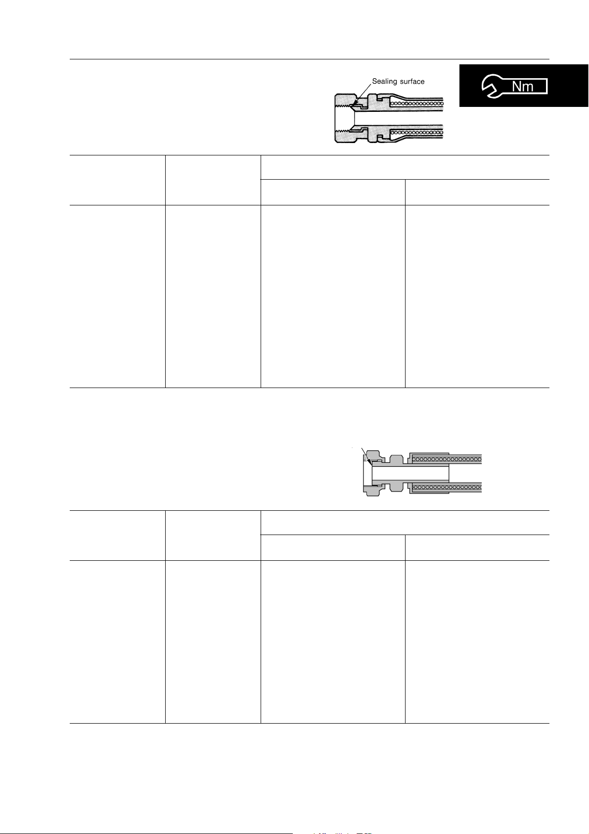
2. TIGHTENING TORQUE FOR NUTS OF FLARED
Use these torques for nut part of flared.
STANDARD TIGHTENING TORQUE
Thread diameter
of nut part
(mm)
1/2” - 20
9/16” - 18
3/4” - 16
7/8” - 14
1.1/16 - 12
1.5/16 - 12
1.5/8 - 12
22
33
Width across flats
of nut part
(mm)
17
17
22
27
32
38
50
27
41
TIGHTENING TORQUE
kgm Nm
±0.5
2.6
4
±0.5
±2
6.7
8
±2
9.7
±3
±3
17
20
±5
8
±2
±5
20
Sealing surface
25.5
39.2
65.7
78.5
95.15
166.7
196.2
78.5
196.2
±4.9
±4.9
±19.6
±19.6
±29.4
±29.4
±49
±19.6
±49
Thread diameter
of nut part
(mm)
9/16” - 18
11/16” - 16
13/16” - 16
1” - 14
1.3/16 - 12
1.7/16 - 12
1.11/16 - 12
2” - 12
Width across flats
of nut part
(mm)
17
22
24
30
36
41
50
57
TIGHTENING TORQUE
kgm Nm
2.3–2.5
3.4–3.9
5.2–5.8
8.2–9.2
12.2–13.3
15.3–17.3
18.4–20.4
20.4–24.4
23–25
33–38
51–57
80–90
120–130
150–170
180–200
200–240
SK714-5 SK815-5 SK815-5 turbo
00-9

COATING MATERIALS
COATING MATERIALS
The recommended coating materials prescribed in Komatsu Utility Shop Manuals are listed below:
Nomenclature Code Applications
Bostik 99 Used to apply rubber pads, rubber gaskets and cork plugs.
Adhesives
Gasket sealant
Loctite 406
Loctite 222 Used for low resistance locking of screws, check nuts and adjustment nuts.
Loctite 242
Loctite 262 Used for high resistant of threaded parts that can be removed with normal tools.
Loctite 270
Loctite 542 Used for sealing the union threads for hydraulic tubes.
Loctite 573
Loctite 601
Loctite 675
Loctite 542
Loctite 510
Used to apply resin, rubber, metallic and non-metallic parts when a fast, strong
seal is needed.
To prevent the loosening of bolts, nuts and plugs and the leakage of oil. Used for
medium resistance locking of screws and nuts of every type, and for loc king
keys and bearings.
Used for high resistant locking and for sealing threaded parts, bolts and stud
bolts.
Used for sealing rather exact plane surfaces when the option of possible future
dismantling is required.
Used for high resistant locking of mechanical components that can be removed
only after heating
Used to lock cylindrical couplings and for the permanent locking of threaded
parts, and also to lock shafts to bearings, gears, pulleys, pins, bushings, etc.
Used by itself to seal grease fittings, tapered screw fittings and tapered screw
fittings in hydraulic circuits of less than 50 mm in diameter.
Used by itself on mounting flat surface
(Clearance between surfaces within 0.2 mm)
Antifriction compound
(Lubricant including
Molybdenum disulfide)
Grease
(Lithium grease)
Vaseline
00-10
Loctite 518
Litio EP MS2
NLGI 2
Litio EP
NLGI 2
-----
Used by itself on mounting flat surface
(Clearance between surfaces within 0.5 mm
Applied to bearings and taper shaft to facilitate press-fitting and to prevent
sticking, burning or rusting.
Applied to bearings, sliding parts and oil seals for lubrication, rust prevention
and facilitation of assembling work.
Used for protecting battery electrode terminals from corrosion
SK714-5 SK815-5 SK815-5 turbo
ELECTRIC WIRE CODE
ELECTRIC
In the wiring diagrams various colour and symbols are employed to indicate the thickness of wires.
This wire code table will help you understand WIRING DIAGRAMS.
Example: R–N 1.5 indicates a cable having a nominal number 1.5 and red coating with black stripe.
CLASSIFICATION BY THICKNESS
Nominal
number
0.5 16 0.20 0.35 1.55 3.5
1 14 0.30 0.99 2.80 11
1.5 21 0.30 1.48 3.35 14
2.5 35 0.30 2.47 3.80 20
4 56 0.30 3.95 4.60 28
6 84 0.30 5.93 5.20 37
Number
strands
Copper wire
Ø of strands
(mm)
Cross section
(mm)
Cable O.D.
(mm)
Current rating
(A)
CLASSIFICATION BY COLOUR AND CODE
Primary Auxiliary
Code A A–B A/B A–G – A–N A/N A–R A–V A/V
Colour Light Blue Light Blue – White Light Blue–Yellow Light Blue–Black Light Blue–Red Light Blue–Green
Code B B–G – B–N B/N B–R B/R – – – –
Colour White White–Yellow White–Black White–Red – –
Code C C–B C/B C–L – C–N C/N – – – –
Colour Orange Orange–White Orange–Blue Orange–Black – –
Code G G–N G/N – G/R – – – – – –
Colour Yellow Yellow–Black Yellow–Red – – –
Code H H–L – H–N – H–R H/R – – – –
Colour Grey Grey–Blue Grey–Black Grey–Red – –
Code L – L/B L–G L/G L–N L/N L–R L/R – –
Colour Blue Blue–White Blue–Yellow Blue–Black Blue–Red –
Code M M–B M/B M–N – M–V – – – – –
Colour Brown Brown–White Brown–Black Brown–Green – –
CodeN ––––––––––
ColourBlack–––––
Code R R–G – R–N R/N R–V – – – – –
Colour Red Red–Yellow Red–Black Red–Green – –
Code S S–G – S–N S/N – – – – – –
Colour Pink Pink–Yellow Pink–Black – – –
Code V V–B V/B V–N V/N – – – – – –
Colour Green Green–White Green–Black – – –
Code Z Z–B – Z–N Z/N – – – – – –
Colour Violet Violet–White Violet–Black – – –
COMPOSITION OF THE COLOURS
The coloration of two-colour wires is indicated by the composition of the symbol listed.
Example: G–V = Yellow-Green with longitudinal colouring
G/V = Yellow-Green with transversal colouring
SK714-5 SK815-5 SK815-5 turbo
00-11

WEIGHT TABLE
WEIGHT TABLE
This weight table is a guide for use when transporting or handling components.
Unit: kg
Machine model SK714-5 SK815-5 SK815-5 turbo
Engine assembly - Muffler - Exhaust pipe 200 200 200
Radiator 22 22 22
Hydraulic oil tank (without oil) 21.5 21.5 21.5
Engine hood 14.5 14.5 14.5
Cabin (without seat) 215 215 215
Seat:
• standard
• witj suspension
Engine-pump group 278–285 283–290 283–290
Piston pump:
• standard
• High-Flow
10
16
78
84
10
16
82
88
10
16
82
88
Wheel, assy. (standard) 43 44 44
Control valve:
• 3-spool (standard)
• 4-spool (High-Flow)
Work equipment (without bucket)
• Arm
• Work equipment support
• Bucket (L=1460 mm)
• Tilt cylinder
• Dump cylinder
19
21.5
280
49
159
17,3
12
19
21.5
295
49
171,5
16,8
12
19
21.5
295
49
171,5
16,8
12
00-12
SK714-5 SK815-5 SK815-5 turbo
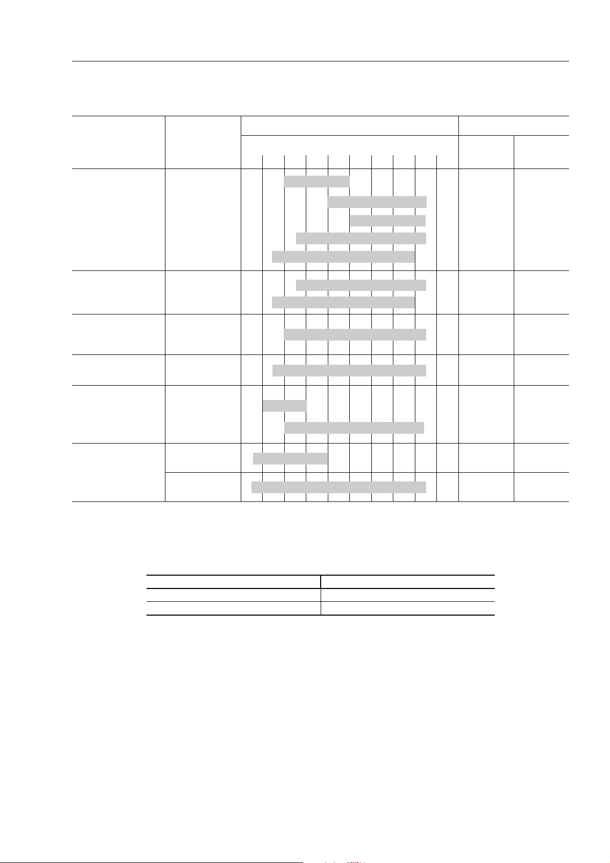
TABLE OF OIL AND COOLANT QUANTITIES
TABLE OF OIL AND COOLANT QUANTITIES
RESERVOIR
Engine oil pan
Hydraulic system
and hydrostatic
trasmissione
Hydraulic circuit
with biodegradable
oil
Final transmission
case (ea.)
Fuel tank DIESEL OIL
KIND OF
FLUID
OIL
• API CD
OIL
• API CD
OIL
• API CD
--
AMBIENT TEMPERATURE CAPACITY (
30 -- 20
✽
--
10 0 10 20 30 40 50°C
SAE 10W
SAE 30
SAE 40
SAE 10W-30
SAE 5W-30
SAE 10W
SAE 5W-30
SAE 10W-30
ASTM D975 N.2
Specified Refill
SK714-5
SK815-5:
SK815-5 turbo:
ᐉ)
88
38 27
38 27
15.5 15.5
38
50
–
Engine cooling
system
WATER +
ANTIFREEZE
PERMANENT
COOLANT
9–
9–
✽ ASTM D975 N.
IMPORTANT:
(1) When the diesel oil sulphur content is less then 0.5%, change the engine oil according to the periodic maintenance
intervals indicated in the operation and maintenance manual. In the diesel oil sulphur content exceeds 0.5% change
the engine oil according to the following table:
Sulphur content Engine oil change interval
from 0.5 to 1.0% 1/2
over 1.0% 1/4
of regular interval
of regular interval
(2) When starting the engine at temperatures below 0 °C, use engine oil SAE 10W, 20W-20 and 10W-30, even if during
the day the temperature increases by 10 °C.
(3) Use engine oil with CD classification; if oil with CD classification is used, reduce the engine oil change interval by a
half.
(4) Use original products, which have characteristics specifically formulated and approved for the engine, the hydraulic
circuit of equipment and for reductions.
First filling quantity:
total quantity of oil, including the oil for the components and pipes.
Oil change quantity:
quantity of oil necessary to fill the system or unit during the normal inspection and maintenance operations.
ASTM: American Society of Testing and Materials
SAE: Society of Automotive Engineers
API: American Petroleum Institute
SK714-5 SK815-5 SK815-5 turbo
00-13

PAGE INTENTIONALLY
LEFT BLANK
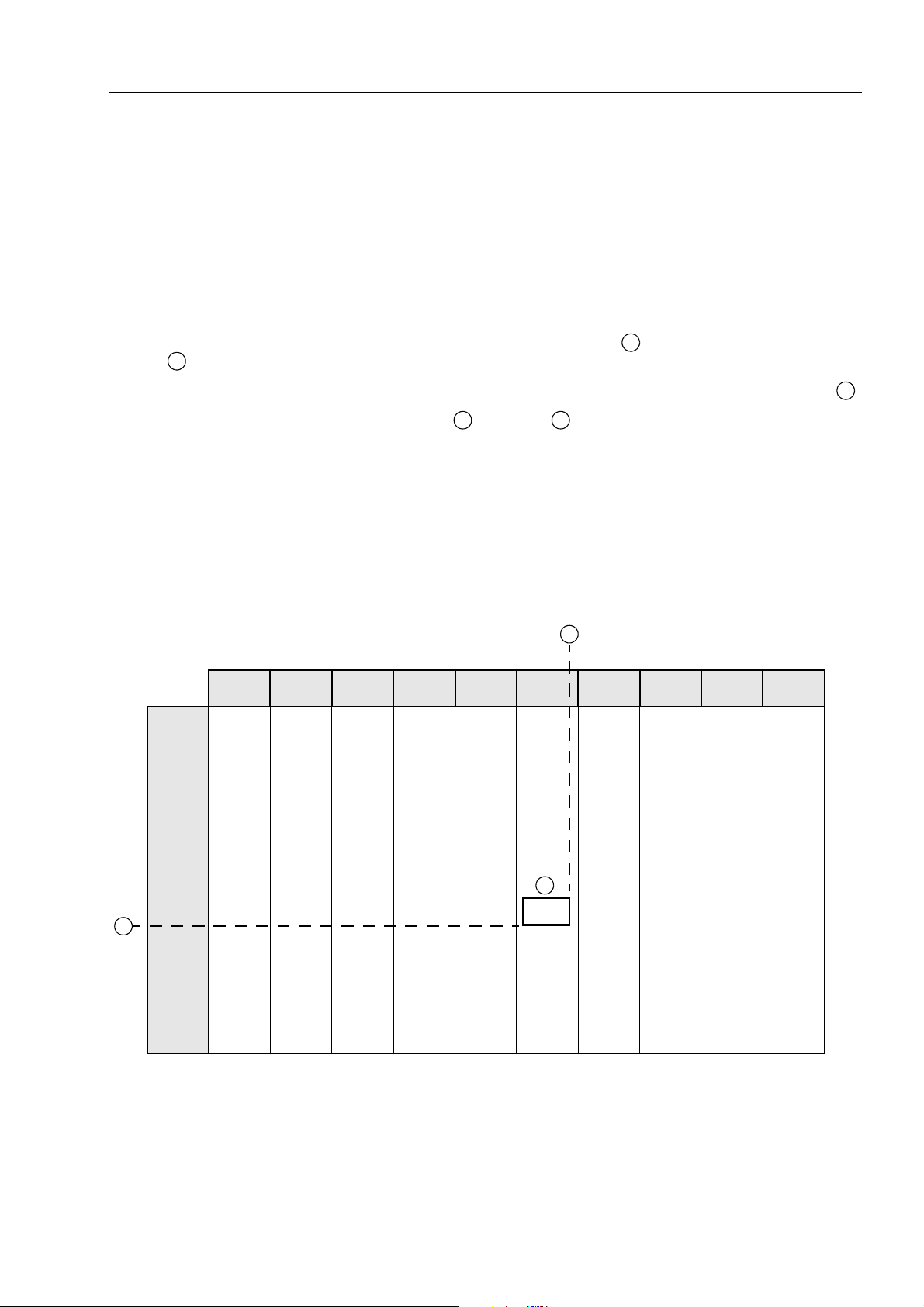
CONVERSION TABLE
METHOD OF USING THE CONVERSION TABLE
The conversion table in this section is provided to enable simple conversion of figures.
For details of the method of using the conversion table, see the example given below.
EXAMPLE
• Method of using the conversion table to convert from millimeters to inches.
1. Convert 55 mm into inches.
CONVERSION TABLE
0.236
0.630
1.024
A
, then drow a horizontal line from
1 mm = 0.03937 in.
0.276
0.669
1.063
0.315
0.709
1.102
0.354
0.748
1.142
1 - Locate the number 50 in the vertical column at the left side, take this as
A
.
2 - Locate the number 5 in the row across the top, take this as , then draw a perpendicular line down from .
3 - Take the point where the two lines cross as . This point gives the value when converting from mil-
limeters to inches. Therefore,
2. Convert 550 mm into inches
1 - The number 550 does not appear in the table, so divide by 10 (move the decimal point one place to the left) to
convert it to 55 mm.
2 - Carry out the same procedure as above to convert 55 mm to 2.165 in.
3 - The original value (550 mm) was divided by 10, so multiply 2.165 in. by 10 (move the decimal point one place to
the right) to return to the original value. This gives 550 mm = 21.65 in.
From millimeters to inches
0 1 2 3 4 5 6 7 8 9
0.039
0.433
0.827
10
20
0
0
0.394
0.787
55 mm =2.165 in.
0.079
0.472
0.866
0.118
0.512
0.906
C C
0.157
0.551
0.945
0.197
0.591
0.984
B
B
30
40
50
1.181
1.575
1.969
1.220
1.614
2.008
A
60
70
80
90
2.362
2.756
3.150
3.543
2.402
2.795
3.189
3.583
SK714-5 SK815-5 SK815-5 turbo
1.260
1.654
2.047
2.441
2.835
3.228
3.622
1.299
1.693
2.087
2.480
2.874
3.268
3.661
1.339
1.732
2.126
2.520
2.913
3.307
3.701
1.378
1.772
C
2.165
2.559
2.953
3.346
3.740
1.417
1.811
2.205
2.598
2.992
3.386
3.780
1.457
1.850
2.244
2.638
3.032
3.425
3.819
1.496
1.890
2.283
2.677
3.071
3.465
3.858
1.536
1.929
2.323
2.717
3.110
3.504
3.898
00-15

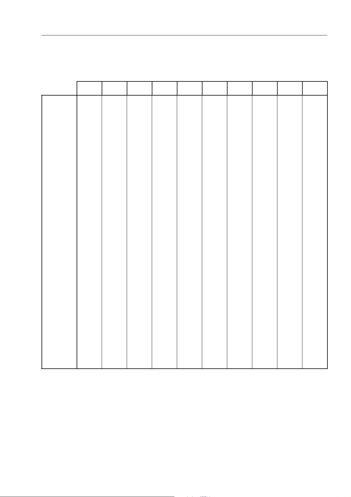
From mm to in.
CONVERSION TABLE
1 mm = 0.03937 in.
0123456789
0
10
20
30
40
50
60
70
80
90
From kg to lb.
0
0.394
0.787
1.181
1.575
1.969
2.362
2.756
3.150
3.543
0.039
0.433
0.827
1.220
1.614
2.008
2.402
2.795
3.189
3.583
0.079
0.472
0.866
1.260
1.654
2.047
2.441
2.835
3.228
3.622
0.118
0.512
0.906
1.299
1.693
2.087
2.480
2.874
3.268
3.661
0.157
0.551
0.945
1.339
1.732
2.126
2.520
2.913
3.307
3.701
0.197
0.591
0.984
1.378
1.772
2.165
2.559
2.953
3.346
3.740
0.236
0.630
1.024
1.417
1.811
2.205
2.598
2.992
3.386
3.780
0.276
0.669
1.063
1.457
1.850
2.244
2.638
3.032
3.425
3.819
0.315
0.709
1.102
1.496
1.890
2.283
2.677
3.071
3.465
3.858
1 kg = 2.2046 lb.
0.354
0.748
1.142
1.536
1.929
2.323
2.717
3.110
3.504
3.898
0
10
20
30
40
50
60
70
80
90
0123456789
0
22.05
44.09
66.14
88.18
110.23
132.28
154.32
176.37
198.42
2.20
24.25
46.30
68.34
90.39
112.44
134.48
156.53
178.57
200.62
4.41
26.46
48.50
70.55
92.59
114.64
136.69
158.73
180.78
202.83
6.61
28.66
50.71
72.75
94.80
116.85
138.89
160.94
182.98
205.03
8.82
30.86
51.91
74.96
97.00
119.05
141.10
163.14
185.19
207.24
11.02
33.07
55.12
77.16
99.21
121.24
143.30
165.35
187.39
209.44
13.23
35.27
57.32
79.37
101.41
123.46
145.51
167.55
189.60
211.64
15.43
37.48
59.53
81.57
103.62
125.66
147.71
169.76
191.80
213.85
17.64
39.68
61.73
83.78
105.82
127.87
149.91
171.96
194.01
216.05
19.84
41.89
63.93
85.98
108.03
130.07
152.12
174.17
196.21
218.26
00-16
SK714-5 SK815-5 SK815-5 turbo

From liter to U.S. Gall.
0123456789
CONVERSION TABLE
1 ᐉ = 0.2642 U.S. Gall.
0
10
20
30
40
50
60
70
80
90
0
2.642
5.283
7.925
10.567
13.209
15.850
18.492
21.134
23.775
From liter to U.K. Gall.
0.264
2.906
5.548
8.189
10.831
13.473
16.115
18.756
21.398
24.040
0.528
3.170
5.812
8.454
11.095
13.737
16.379
19.020
21.662
24.304
0.793
3.434
6.076
8.718
11.359
14.001
16.643
19.285
21.926
24.568
1.057
3.698
6.340
8.982
11.624
14.265
16.907
19.549
22.190
24.832
1.321
3.963
6.604
9.246
11.888
14.529
17.171
19.813
22.455
25.096
1.585
4.227
6.869
9.510
12.152
14.795
17.435
20.077
22.719
25.361
1.849
4.491
7.133
9.774
12.416
15.058
17.700
20.341
22.983
25.625
2.113
4.755
7.397
10.039
12.680
15.322
17.964
20.605
23.247
25.889
1 ᐉ = 0.21997 U.K. Gall.
2.378
5.019
7.661
10.303
12.944
15.586
18.228
20.870
23.511
26.153
0
10
20
30
40
50
60
70
80
90
0123456789
0
2.200
4.399
6.599
8.799
10.998
13.198
15.398
17.598
19.797
0.220
2.420
4.619
6.819
9.019
11.281
13.418
15.618
17.818
20.017
0.440
2.640
4.839
7.039
9.239
11.438
13.638
15.838
18.037
20.237
0.660
2.860
5.059
7.259
9.459
11.658
13.858
16.058
12.257
20.457
0.880
3.080
5.279
7.479
9.679
11.878
14.078
16.278
18.477
20.677
1.100
3.300
5.499
7.969
9.899
12.098
14.298
16.498
18.697
20.897
1.320
3.520
5.719
7.919
10.119
12.318
14.518
16.718
18.917
21.117
1.540
3.740
5.939
8.139
10.339
12.528
14.738
16.938
19.137
21.337
1.760
3.950
6.159
8.359
10.559
12.758
14.958
17.158
19.357
21.557
1.980
4.179
6.379
8.579
10.778
12.978
15.178
17.378
19.577
21.777
SK714-5 SK815-5 SK815-5 turbo
00-17

From Nm to lb.ft.
0123456789
CONVERSION TABLE
1 Nm = 0.737 lb.ft.
0
10
20
30
40
50
60
70
80
90
100
110
120
0
7.370
14.740
22.110
29.480
36.850
44.220
51.590
58.960
66.330
73.700
81.070
88.440
0.737
8.107
15.477
22.847
30.217
37.587
44.957
52.327
59.697
67.067
74.437
81.807
89.177
1.474
8.844
16.214
23.584
30.954
38.324
45.694
53.064
60.434
67.804
75.174
82.544
89.914
2.211
9.581
16.951
24.321
31.691
39.061
46.431
53.801
61.171
68.541
75.911
83.281
90.651
2.948
10.318
17.688
25.058
32.428
39.798
47.168
54.538
61.908
69.278
76.648
84.018
91.388
3.685
11.055
18.425
25.795
33.165
40.535
47.905
55.275
82.645
70.015
77.385
84.755
92.125
4.422
11.792
19.162
26.532
33.902
41.272
48.642
56.012
63.382
70.752
78.122
85.492
92.862
5.159
12.529
19.899
27.269
34.639
42.009
49.379
56.749
64.119
71.489
78.859
86.229
93.599
5.896
13.266
20.636
28.006
35.376
42.746
50.116
57.486
64.856
72.226
79.596
86.966
94.336
6.633
14.003
21.373
28.743
36.113
43.483
50.853
58.223
65.593
72.963
80.333
87.703
95.073
130
140
150
160
170
180
190
95.810
103.180
110.550
117.920
125.290
132.660
140.030
96.547
103.917
111.287
118.657
126.027
133.397
140.767
97.284
104.654
112.024
119.394
126.764
134.134
141.504
98.021
105.391
112.761
120.131
127.501
134.871
142.241
98.758
106.128
113.498
120.868
128.238
135.608
142.978
99.495
106.865
114.235
121.605
128.975
136.345
143.715
100.232
107.602
114.972
122.342
129.712
137.082
144.452
100.969
108.339
115.709
123.079
130.449
137.819
145.189
101.706
109.076
116.446
123.816
131.186
138.556
145.926
102.443
109.813
117.183
124.553
131.923
139.293
146.663
00-18
SK714-5 SK815-5 SK815-5 turbo
From Nm to kgm
0123456789
CONVERSION TABLE
1 Nm = 0.102 kgm
0
10
20
30
40
50
60
70
80
90
100
110
120
0
1.020
2.040
3.060
4.080
5.100
6.120
7.140
8.160
9.180
10.200
11.220
12.240
0.102
1.222
2.142
3.162
4.182
5.202
6.222
7.242
8.262
9.282
10.302
11.322
12.342
0.204
1.224
2.244
3.264
4.284
5.304
6.324
7.344
8.364
9.384
10.404
11.424
12.444
0.306
1.326
2.346
3.366
4.386
5.406
6.426
7.446
8.466
9.486
10.506
11.526
12.546
0.408
1.428
2.448
3.468
4.488
5.508
6.528
7.548
8.568
9.588
10.608
11.628
12.648
0.510
1.530
2.550
3.570
4.590
5.610
6.630
7.650
8.670
9.690
10.710
11.730
12.750
0.612
1.632
2.652
3.672
4.692
5.712
6.732
7.752
8.772
9.792
10.812
11.832
12.852
0.714
1.734
2.754
3.774
4.794
5.814
6.834
7.854
8.874
9.894
10.914
11.934
12.954
0.816
1.836
2.856
3.876
4.896
5.916
6.936
7.956
8.976
9.996
11.016
12.036
13.056
0.918
1.938
2.958
3.978
4.998
6.018
7.038
8.058
9.078
10.098
11.118
12.138
13.158
130
140
150
160
170
180
190
13.260
14.280
15.300
16.320
17.340
18.360
19.380
13.362
14.382
15.402
16.422
17.442
18.462
19.482
13.464
14.484
15.504
16.524
17.544
18.564
19.584
13.566
14.586
15.606
16.626
17.646
18.666
19.686
13.668
14.688
15.708
16.728
17.748
18.768
19.788
13.770
14.790
15.810
16.830
17.850
18.870
19.890
13.872
14.892
15.912
16.932
17.952
18.972
19.992
13.974
14.994
16.014
17.034
18.054
19.074
20.094
14.076
15.096
16.116
17.136
18.156
19.176
20.196
14.178
15.198
16.218
17.238
18.258
19.278
20.298
SK714-5 SK815-5 SK815-5 turbo
00-19
From kgm to lb.ft.
0123456789
CONVERSION TABLE
1 kgm = 7.233 lb.ft.
0
10
20
30
40
50
60
70
80
90
100
110
120
0
72.3
144.7
217.0
289.3
361.7
434.0
506.3
578.6
651.0
723.3
795.6
868.0
7.2
79.6
151.9
224.2
296.6
368.9
441.2
513.5
585.9
658.2
730.5
802.9
875.2
14.5
86.8
159.1
231.5
303.8
376.1
448.5
520.8
593.1
665.4
737.8
810.1
882.4
21.7
94.0
166.4
238.7
311.0
383.4
455.7
528.0
600.3
672.2
745.0
817.3
889.7
28.9
101.3
173.6
245.9
318.3
390.6
462.9
535.2
607.6
679.9
752.2
824.6
896.9
36.2
108.5
180.8
253.2
325.5
397.8
470.2
542.5
614.8
687.1
759.5
831.8
904.1
43.4
115.7
188.1
260.4
332.7
405.1
477.4
549.7
622.0
694.4
766.7
839.0
911.4
50.6
123.0
195.3
267.6
340.0
412.3
484.6
556.9
629.3
701.6
773.9
846.3
918.6
57.9
130.2
202.5
274.9
347.2
419.5
491.8
564.2
636.5
708.8
781.2
853.5
925.8
65.1
137.4
209.8
282.1
354.4
426.8
499.1
571.4
643.7
716.1
788.4
860.7
933.1
130
140
150
160
170
180
190
940.3
1012.6
1084.9
1157.3
1129.6
1301.9
1374.3
947.5
1019.9
1092.2
1164.5
1236.8
1309.2
1381.5
954.8
1027.1
1099.4
1171.7
1244.1
1316.4
1388.7
962.0
1034.3
1106.6
1179.0
1251.3
1323.6
1396.0
969.2
1041.5
1113.9
1186.2
1258.5
1330.9
1403.2
876.5
1048.8
1121.1
1193.4
1265.8
1338.1
1410.4
983.7
1056.0
1128.3
1200.7
1273.0
1345.3
1417.7
990.9
1063.2
1135.6
1207.9
1280.1
1352.6
1424.9
998.2
1070.5
1142.8
1215.1
1287.5
1359.8
1432.1
1005.4
1077.7
1150.0
1222.4
1294.7
1367.0
1439.4
00-20
SK714-5 SK815-5 SK815-5 turbo
From bar to psi (lb/in2)
0123456789
CONVERSION TABLE
1 bar = 14.503 psi
0
10
20
30
40
50
60
70
80
90
100
110
120
0
145.0
290.0
435.1
580.1
725.1
870.2
1015.2
1160.2
1305.3
1450.3
1595.3
1740.4
14.5
159.5
304.6
449.6
594.6
739.6
884.7
1029.7
1174.7
1319.8
1464.8
1609.8
1754.9
29.0
174.0
319.1
464.1
609.1
754.1
899.2
1044.2
1189.2
1334.3
1479.3
1624.3
1769.4
43.5
188.5
333.6
478.6
623.6
768.6
913.7
1058.7
1203.7
1348.8
1493.8
1638.8
1783.9
58.0
203.0
348.1
493.1
638.1
783.2
928.2
1073.2
1218.2
1363.3
1508.3
1653.3
1798.4
72.5
217.5
362.6
507.6
652.6
797.7
942.7
1087.7
1232.7
1377.8
1522.8
1667.8
1812.9
87.0
232.0
377.1
522.1
667.1
812.2
957.2
1102.2
1247.2
1392.3
1537.3
1682.3
1827.4
101.5
246.5
391.6
536.6
681.6
826.7
971.7
1116.7
1261.8
1406.8
1551.8
1696.8
1841.9
116.0
261.0
406.1
551.1
696.1
841.2
986.2
1131.2
1276.3
1421.3
1566.3
1711.3
1856.4
130.5
275.6
420.6
565.6
710.6
855.7
1000.7
1145.7
1290.8
1435.8
1580.8
1725.8
1870.8
130
140
150
160
170
180
190
200
210
220
230
240
1885.4
2030.4
2175.4
2320.5
2465.5
2610.5
2755.6
2900.6
3045.6
3190.7
3335.7
3480.7
1899.9
2044.9
2189.9
2335.0
2480.0
2625.0
2770.0
2915.1
3060.1
3205.2
3350.2
3495.2
1914.4
2059.4
2204.4
2349.5
2494.5
2639.5
2784.6
2929.6
3074.6
3219.7
3364.7
3509.7
1928.9
2073.9
2218.9
2364.0
2509.0
2654.0
2799.1
2944.1
3089.1
3234.2
3379.2
3524.2
1943.4
2088.4
2233.5
2378.5
2523.5
2668.5
2813.6
2958.6
3103.6
3248.7
3393.7
3538.7
1957.9
2102.9
2248.0
2393.0
2538.0
2683.0
2828.1
2973.1
3118.1
3263.2
3408.2
3553.2
1972.4
1217.4
2262.5
2407.5
2552.5
2697.7
2842.6
2987.6
3132.6
3277.7
3422.7
3567.7
1986.9
2131.9
2277.0
2422.0
2567.0
2712.1
2857.1
3002.1
3147.1
3192.2
3437.2
3582.2
2001.4
2146.4
2291.5
2436.5
2581.5
2726.6
2871.6
3016.6
3161.6
3306.7
3451.7
3596.7
2015.9
2160.9
2306.0
2451.0
2596.0
2641.1
2886.1
3031.1
3176.1
3321.2
3466.2
3611.2
SK714-5 SK815-5 SK815-5 turbo
00-21
CONVERSION TABLE
TEMPERATURE
Fahrenheit-Centigrade conversion; a simple way to convert a Fahrenhe it temperature reading int o a Centigrade temperature reading or vice versa is to enter the accompanying table in the center or boldface column of figures.
These figures refer to the temperature in either Fahrenheit or Centigrade degrees.
If it is desired to convert from Fahrenheit to Centigrade degrees, consider the center column as a table of Fahrenheit temperatures and read the corresponding Centigrade temperature in the column at the left.
If it is desired to convert from Centigrade to Fahrenheit degrees, consider the center column as a table of Centigrade values and read the corresponding Fahrenheit temperature on the right.
1 °C = 33.8°F
°C
–40.4
–37.2
–34.4
–31.7
–28.9
–28.3
–27.8
–27.2
–26.7
–26.1
–25.6
–25.0
–24.4
–23.9
–23.3
–22.8
–22.2
–21.7
–21.1
–20.6
–40
–35
–30
–25
–20
–19
–18
–17
–16
–15
–14
–13
–12
–11
–10
–9
–8
–7
–6
–5
°F °C °F °C °F °C °F
–40.0
–31.0
–22.0
–13.0
–4.0
–2.2
–0.4
1.4
3.2
5.0
6.8
8.6
10.4
12.2
14.0
15.8
17.6
19.4
21.2
23.0
–11.7
–11.1
–10.6
–10.0
–9.4
–8.9
–8.3
–7.8
–7.2
–6.7
–6.1
–5.6
–5.0
–4.4
–3.9
–3.3
–2.8
–2.2
–1.7
–1.1
11
12
13
14
15
16
17
18
19
20
21
22
23
24
25
26
27
28
29
30
51.8
53.6
55.4
57.2
59.0
60.8
62.6
64.4
66.2
68.0
69.8
71.6
73.4
75.2
77.0
78.8
80.6
72.4
84.2
86.0
7.8
8.3
8.9
9.4
10.0
10.6
11.1
11.7
12.2
12.8
13.3
13.9
14.4
15.0
15.6
16.1
16.7
17.2
17.8
18.3
46
47
48
49
50
51
52
53
54
55
56
57
58
59
60
61
62
63
64
65
144.8
116.6
118.4
120.2
122.0
123.8
125.6
127.4
129.2
131.0
132.8
134.6
136.4
138.2
140.0
141.8
143.6
145.4
147.2
149.0
27.2
27.8
28.3
28.9
29.4
30.0
30.6
31.1
31.7
32.2
32.8
33.3
33.9
34.4
35.0
35.6
36.1
36.7
37.2
37.8
81
82
83
84
85
86
87
88
89
90
91
92
93
94
95
96
97
98
99
100
117.8
179.6
181.4
183.2
185.0
186.8
188.6
190.4
192.2
194.0
195.8
197.6
199.4
201.2
203.0
204.8
206.6
208.4
210.2
212.0
–20.0
–19.4
–18.9
–18.3
–17.8
–17.2
–16.7
–16.1
–15.6
–15.0
–14.4
–13.9
–13.3
–12.8
–12.2
00-22
–4
–3
–2
–1
10
24.8
26.6
28.4
30.2
0
32.0
1
33.8
2
35.6
3
37.4
4
39.2
5
41.0
6
42.8
7
44.6
8
46.4
9
48.2
50.0
–0.6
0.0
0.6
1.1
1.7
2.2
2.8
3.3
3.9
4.4
5.0
5.6
6.1
6.7
7.2
31
32
33
34
35
36
37
38
39
40
41
42
43
44
45
87.8
89.6
91.4
93.2
95.0
96.8
98.6
100.4
102.2
104.0
105.8
107.6
109.4
111.2
113.0
18.9
19.4
20.0
20.6
21.1
21.7
22.2
22.8
23.3
23.9
24.4
25.0
25.6
26.1
26.7
66
67
68
69
70
71
72
73
74
75
76
77
78
79
80
150.8
152.6
154.4
156.2
158.0
159.8
161.6
163.4
165.2
167.0
168.8
170.6
172.4
174.2
176.0
40.6
43.3
46.1
48.9
51.7
54.4
57.2
60.0
62.7
65.6
68.3
71.1
73.9
76.7
79.4
105
110
115
120
125
130
135
140
145
150
155
160
165
170
175
221.0
230.0
239.0
248.0
257.0
266.0
275.0
284.0
2930
302.0
311.0
320.0
329.0
338.0
347.0
SK714-5 SK815-5 SK815-5 turbo

STRUCTURE AND FUNCTION
P.T.O......................................................................... 2
Power train ................................................................3
Transmission ............................................................. 4
Final drive.................................................................. 6
Hydraulic circuit
SK714-5 (Standard)................................................. 13
Hydraulic circuit
SK714-5 (Road homologation)................................ 14
Hydraulic circuit
SK815-5 - SK815-5 turbo (Standard)...................... 15
Hydraulic circuit
SK815-5 - SK815-5 turbo (Road homologation)...... 16
Hydraulic pump........................................................ 17
Control valve (3-Spool)............................................ 36
Control valve (4-Spool)............................................ 39
CLSS....................................................................... 43
Solenoid valve......................................................... 51
Accumulator............................................................. 53
Pattern change valve (Optional)...............................54
R.H. PPC Valve (Standard)......................................58
R.H. PPC Valve (Pattern Change) (Optional) ..........62
L.H. PPC Valve (Standard) ......................................66
L.H. PPC VALVE (Pattern Change) (Optional) ........70
Cylinders ..................................................................74
Electrical diagram (Engine line)................................75
Electrical diagram (Frame line standard) .................79
Electrical diagram (Frame line optional) ..................83
Electrical diagram (Cabin line standard) ..................87
Electrical diagram (Cabin line optional)....................93
Electrical diagram (Top-cabin light line standard)..101
Electrical diagram (Top-cabin light line omologation).103
Electrical diagram (Top-cabin light line optional)....105
SK714-5 SK815-5 SK815-5 turbo
10-1
STRUCTURE AND FUNCTION
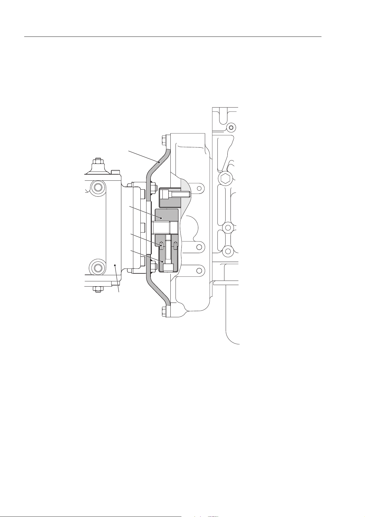
P.T.O.
P. T. O .
4
1
2
3
5
RKS01090
1. Joint
2. Spring pin
3. Dumper
4. Flywheel cover
5. Hydraulic pump
10-2
SK714-5 SK815-5 SK815-5 turbo

STRUCTURE AND FUNCTION
POWER TRAIN
POWER TRAIN
1. Engine
2. Hydraulic pump
3. Control valve
4. Solenoid valve
4a. Servocontrol
4b. Speed increment
4c. Parking brake
8
4
3
ABC
5
7
6
8
5. High-flow solenoid valve
6. L.H. final drive
7. R.H. final drive
8. Axle
8
1
2
8
RKS00990
SK714-5 SK815-5 SK815-5 turbo
10-3
STRUCTURE AND FUNCTION
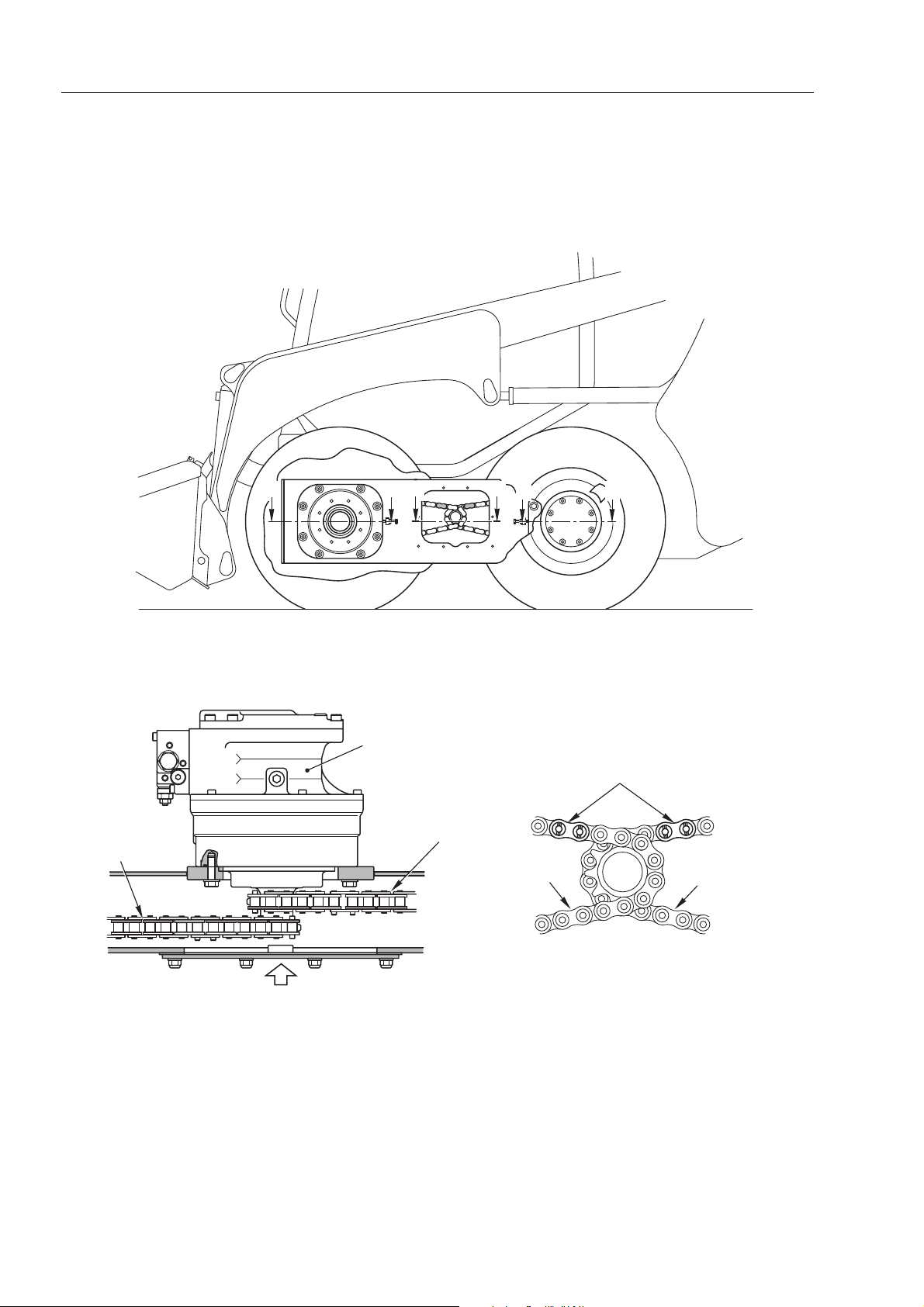
TRANSMISSION
B B
A
A
C C
TRANSMISSION
3
Section A - A
1. L.H. final drive
2. Front trasmission chain
3. Rear trasmission chain
4. Master link
X
1
4
2
2
View X
3
RKS01001
10-4
SK714-5 SK815-5 SK815-5 turbo
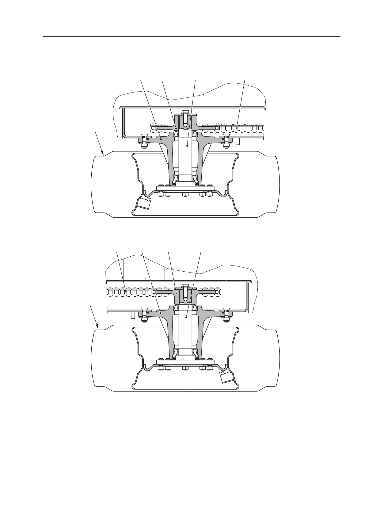
STRUCTURE AND FUNCTION
1
TRANSMISSION
4532
Section B - B
4372
6
Section C -C
RKS01010
1. Front wheel
2. Axle housing
3. Sprocket
4. Shaft
5. Front trasmission chain
6. Rear wheel
7. Rear trasmission chain
SK714-5 SK815-5 SK815-5 turbo
10-5

STRUCTURE AND FUNCTION
FINAL DRIVE
FINAL DRIVE
Z
A
View Z
L.H. FINAL DRIVE
a. A Port – To hydraulic pump (PA2 port)
b. B Port – To hydraulic pump (PB2 port)
c. PP1 Port – From solenoid valve group ST1(A Port)
(2nd speed)
d. PP2 Port – From solenoid valve group ST1 (C Port)
(parking brake)
e. DR Port – To hydraulic tank
d
ce
b
A
a
RKS01020
R.H. FINAL DRIVE
a. A Port – To hydraulic pump (PB1 port)
b. B Port – To hydraulic pump (PA1 port)
c. PP1 Port – From solenoid valve group ST1(A Port)
(2nd speed)
d. PP2 Port – From solenoid valve group ST1 (C Port)
(parking brake)
e. DR Port – To hydraulic tank
10-6
SK714-5 SK815-5 SK815-5 turbo

STRUCTURE AND FUNCTION
FINAL DRIVE
B
B
45 6
7
1
23
22
8
9
10
11
12
13
14
15
16
17
18192021
Section A - A
1. Shaft
2. Bearing
3. Bearing
4. Body
5. Pin
6. Gear
7. Shoe
8. Brake piston
9. Plate
10. Cylinder block
11. Bearing
12. Spring
13. Piston
14. Brake spring
15. Bushing
16. Retainer plate
26
27
25
24
26
23
17. Swash plate
18. Plate
19. Shaft
20. Flange
21. Collar
22. Gasket
23. Plug
24. Spring
Section B - B
2928
RKS01031
25. Spool
26. Plug
27. Spool
28. Plug
29. Spring
SK714-5 SK815-5 SK815-5 turbo
10-7

STRUCTURE AND FUNCTION
DESCRIPTION
The final drive motor consists of:
1. 2-speed hydraulic motor
2. Selector valve
3. Reduction gearing
1. HYDRAULIC MOTOR
Function
The hydraulic motor is of the axial piston type, and converts hydraulic energy supplied by the pump into rotary motion.
Operation
The hydraulic oil arriving from the selector valve is sent on to the valve plate (1). When the oil is sent to port “A” of the
valve, it flows into the corresponding port on the cylinder block (2) and presses against the pistons (3).
This pressure is converted into rotary motion by a swash plate (4) and hence transmitted to the shaft (5). The shaft and
the cylinder block have been integrated into one piece by means of splined toothing.
The return oil is sent to the pump through port “B”.
Rotation in the opposite direction is achieved by sending the oil to port “B” instead of to port “A”..
FINAL DRIVE
5
4
2
1
3
B
A
RKS01050
Varying the displacement
The swash plate (4), which has two surfaces “A” and “B” on the side opposite the sliding side for the shoes (6), is supported by two bearings (7) attached to the body of the motor (8).
The position of the bearings is eccentric with respect to the axis of the shaft and when running at low speed the surface
“A” remains in contact with the body of the motor through the pressure exerted by the pistons (3) and by the force of a
spring (9) mounted in the cylinder block (2).
The angle of the swash plate is
When an increase in speed is demanded, the oil is sent under pressure to the command piston (10). The command piston (10) moves to the left ( ) until the surface “B” makes contact with the housing and the angle of the swash plate
becomes
β (the displacement of the motor is reduced).
α.
10-8
SK714-5 SK815-5 SK815-5 turbo

STRUCTURE AND FUNCTION
.
FINAL DRIVE
8
10
B
8
10
B
6
4
7
A
␣
23
9
Brake
The hydraulic motor is equipped with a negative brake.
• When the motor is at a standstill, or when the operator applies the brake, the braking piston (1) is pushed to the left
( ) by the force of the springs (2).
The friction disk (3), which has b een integrated with the cylinder block by means of semicircular groo ves, is compressed between steel disks (4) and (5), which are integrated with the housing, and is thus blocked. The drive shaft
(6) can therefore no longer turn.
• When the motor is running and the operator disengages the brake, oil is sent under pressure to the chamber “A”.
The force exerted by the oil is greater than the force of the springs (2) and the piston (1) is therefore pushed to the
right ( ) thus releasing the friction disk (3) and permitting rotation of the cylinder block (7) (and also of the drive
shaft).
4
3
3
7
A

923
RKS01040
5
3
4
7
6
SK714-5 SK815-5 SK815-5 turbo
A
1
2
5
3
1
2
4
7
A
6
RKS01060
10-9

STRUCTURE AND FUNCTION
FLUSHING RELIEF VALVE
2.
When the oil is sent under pressure to the “A” port, the oil that activated the motor returns to the pump through the “B”
port.
The pressurised oil sent to the “A” port is also introduced into the chamber “C”. It now pushes the selector valve (1) to
the right ( ). This opens communication between the “B” port and the oil gallery “D”, which is connected to the overpressure limitation valve (2).
If the pressure present at port “B” exceeds the calibration value of the overpressure limitation valve (2), this valve will
open and discharge the excess oil into the reduction gears.
The valve also functions in the same way when the pressurised oil is sent to the “B” port. The only difference is that the
selector valve moves to the left ( ), and the oil gallery “D” communicates with the “A” port.
.
FINAL DRIVE
C
2
D
1
AB
C
2
D
1
AB
RKS01070
10-10
SK714-5 SK815-5 SK815-5 turbo

STRUCTURE AND FUNCTION
REDUCTION GEARING
3.
Function
This final drive motor is equipped with a one-stage epicycloidal reduction gear that converts the high rotation speed and
low torque of the hydraulic motor into low speed and high torque at the swing pinion.
Operating principle
The rotary movement of the output shaft of the motor is transmitted to the gear (s1) and hence to the bevel gears (b1) which are integrated with the planetary gear (1).
Since the gear (a1) is fixed with respect to the output shaft of the hydraulic motor, the planeta ry gear is obliged to turn, moving with it the output shaft (2) of the reduction gearing (connected to the planetary gear by means of grooved toothing).
The reduction ratio of the rotation speed is described by the formula:
R= Zs1/(Zs1+Za1)
Zs1= number of sun gear teeth
Za1= number of ring gear teeth
FINAL DRIVE
b1
1
2
a1
s1
RKS01080
SK714-5 SK815-5 SK815-5 turbo
10-11

PAGE INTENTIONALLY
LEFT BLANK

STRUCTURE AND FUNCTION
HYDRAULIC CIRCUIT SK714-5 (STANDARD)
13
ø
12.7L=3450
(
/
-16Orfs)
12.7L=3450
16
13
(
/
-16Orfs)
16
P
Lift arm
raise
Lift arm cylinder L.H.
Lift arm cylinder R.H.
Bucket cylinder L.H.
ø
9.5L=530
ø
9.5L=530
13
(
ø
9.5L=1100
ø
9.5L=1750
ø
9.5L=1100
ø
9.5L=1750
/
-16Orfs)
16
ø
16 t=2
ø
16 t=2
13
(
/
-16Orfs)
16
13
(
/
-16Orfs)
16
13
(
/
-16Orfs)
16
13
(
/
-16Orfs)
16
13
(
/
-16Orfs)
16
ø
P
Bucket dump
HYDRAULIC CIRCUIT SK714-5 (STANDARD)
P2 P4 P3
P1
T
P
6.5L=400(1/2-20 Jic)
ø
A3
B3
PA3
6.5L=400(1/2-20 Jic)
ø
-18 Jic)
16
/
9
6.5L=600(
ø
-18 Jic)
16
/
9
6.5L=680(
ø
Pout 1 Pout 3 Pout 2 Pout 4
-20 Jic)
-20 Jic)
2
/
1
6.4L=435(
ø
-20 Jic)
2
/
1
6.4L=435(
ø
2
/
1
6.4L=435(
ø
A2
P
B2
ø6.
4L=1500(1/2-20 Jic)
PA2
A1
Unload
valve
B1
PA1
Lift arm lower
Relief valve
19.1MPa
(195kg/cm
2
)
ø
6.4L=1500(1/2-20 Jic)
ø6.
4L=950(1/2-20 Jic)
ø6.
4L=950(1/2-20 Jic)
-20 Jic)
2
/
1
6.4L=435(
ø
100 Mesh
-18 Jic)
16
/
9
10L=520(
ø
-18 Jic)
16
/
9
10L=520(
ø
-18 Jic)
16
10L=1050
/
9
ø
(
P1
-20 Jic)
2
/
1
6.4L=435(
ø
P2P4P3
-20 Jic)
2
/
1
6.4L=435(
ø
-20 Jic)
2
/
1
6.4L=435(
ø
-18 Jic)
16
10L=1050
/
9
ø
(
-20 Jic)
2
/
1
6.4L=435(
ø
100 Mesh
-18 Jic)
16
/
9
10L=520(
ø
-18 Jic)
16
/
9
10L=520(
ø
Bucket cylinder R.H.
Travel motor L.H.
DR
PP2
PP1
A
6.5L=600
ø
(9/16-18 JIC)
6.5L=500
ø
9
/16-18 JIC)
(
BA
RED
ø
9.5L=530
13
(
/
-16Orfs)
16
ø
9.5L=530
13
(
/
-16Orfs)
16
13
ø
12.7L=1800(
/
-16Orfs)
16
13
ø
12.7L=1800(
/
-16Orfs)
16
13
ø
12.7L=3450(
/
-16Orfs)
ø
16 t=2
ø
16 t=2
PP1
B
ø
ø
ø
ø
16
13
ø
12.7L=3450(
/
-16Orfs)
16
15.9L=950(1”3/16-12 Orfs)
15.9L=950(1”3/16-12 Orfs)
15.9L=950(1”3/16-12 Orfs)
15.9L=950(1”3/16-12 Orfs)
PP2
P
ø
19.1L=1100(1”3/16-12 Orfs)
ø
20L=1000
ø
9.5L=1050(9/16-18 JIC)
T
T
-20 Jic)
-20 Jic)
-20 Jic)
-20 Jic)
2
2
2
2
/
/
/
/
1
1
1
1
6.4L=950(
6.4L=850(
6.4L=650(
6.4L=650(
ø
ø
ø
ø
P4
S3 S4
Engine
4D88E-E1FD
34.7km/2800rpm
PA1 DA1 DB1 DB2 DA2 PA2
E
±40cm3/rev
PB1
E2
±40cm3/rev
T5
PB2
ABC
SV3SV2SV1
P
T
RED
DR
Travel motor R.H.
SK714-5 SK815-5 SK815-5 turbo
ø
9.5L=1300(9/16-18 Jic)
ø
9.5L=1300(9/16-18 Jic)
-12 JIC)
16
/
19.1L=800
1
ø
(1”
-12 JIC)
16
/
19.1L=850
1
ø
(1”
ø
(1”
19L=1650
1
/16-12 JIC)
-12 JIC)
16
/
25.4L=620
5
ø
(1”
ø
ø
16
t.2
19L=1450(1”5/16-12 JIC)
ø
20
-12 JIC)
16
/
25.4L=500
5
ø
(1”
ø
9.5L=1000(9/16-18 Jic)
ø
6.5L=350(9/16-18 Jic)
ø
6.5L=680(9/16-18 Jic)
10-13

STRUCTURE AND FUNCTION
HYDRAULIC CIRCUIT SK714-5 (ROAD HOMOLOGATION)
13
ø
12.7L=3450
(
/
-16Orfs)
12.7L=3450
16
13
(
/
-16Orfs)
16
P
P
Bucket dump
P
Lift arm
raise
Unload
valve
Lift arm cylinder L.H.
Lift arm cylinder R.H.
Bucket cylinder L.H.
ø
9.5L=530
ø
9.5L=530
13
(
ø
9.5L=1100
ø
9.5L=1750
ø
9.5L=1100
ø
9.5L=1750
/
-16Orfs)
16
ø
16 t=2
ø
16 t=2
13
(
/
-16Orfs)
16
13
(
/
-16Orfs)
16
13
(
/
-16Orfs)
16
13
(
/
-16Orfs)
16
13
(
/
-16Orfs)
16
ø
6.5L=400(1/2-20 Jic)
ø
A3
B3
PA3
A2
B2
PA2
A1
B1
PA1
Lift arm lower
Relief valve
19.1MPa
(195kg/cm
6.5L=400(1/2-20 Jic)
ø
2
)
ø6.
4L=1500(1/2-20 Jic)
ø
6.4L=1500(1/2-20 Jic)
ø6.
4L=950(1/2-20 Jic)
ø6.
4L=950(1/2-20 Jic)
T
P
-18 Jic)
16
/
9
6.5L=600(
ø
-18 Jic)
16
/
9
6.5L=680(
ø
P2 P4 P3
P1
Pout 1 Pout 3 Pout 2 Pout 4
-20 Jic)
-20 Jic)
2
/
1
6.4L=435(
ø
-20 Jic)
2
/
1
6.4L=435(
ø
2
/
1
6.4L=435(
ø
-20 Jic)
2
/
1
6.4L=435(
ø
100 Mesh
-18 Jic)
16
/
9
10L=520(
ø
HYDRAULIC CIRCUIT SK714-5 (ROAD HOMOLOGATION)
100 Mesh
-18 Jic)
16
/
9
10L=520(
ø
-18 Jic)
16
10L=1050
/
9
ø
(
P1
-20 Jic)
2
/
1
6.4L=435(
ø
P2P4P3
-20 Jic)
2
/
1
6.4L=435(
ø
-20 Jic)
2
/
1
6.4L=435(
ø
-20 Jic)
2
/
1
6.4L=435(
ø
-18 Jic)
16
/
9
10L=520(
ø
-18 Jic)
16
/
9.5L=1050
9
(
ø
-18 Jic)
16
/
9
10L=520(
ø
Bucket cylinder R.H.
Travel motor L.H.
DR
A
PP2
6.5L=600
ø
(9/16-18 JIC)
ø
6.5L=500
9
/16-18 JIC)
(
BA
PP1
RED
ø
9.5L=530
13
(
/
-16Orfs)
16
ø
9.5L=530
13
(
/
-16Orfs)
16
13
ø
12.7L=1800(
/
-16Orfs)
16
13
ø
12.7L=1800(
/
-16Orfs)
16
13
ø
12.7L=3450(
/
-16Orfs)
ø
16 t=2
ø
16 t=2
PP1
B
ø
ø
ø
ø
16
13
ø
12.7L=3450(
/
-16Orfs)
16
15.9L=950(1”3/16-12 Orfs)
15.9L=950(1”3/16-12 Orfs)
15.9L=950(1”3/16-12 Orfs)
15.9L=950(1”3/16-12 Orfs)
PP2
P
ø
19.1L=1100(1”3/16-12 Orfs)
ø
20L=1000
ø
9.5L=1050(9/16-18 JIC)
T
T
-20 Jic)
-20 Jic)
-20 Jic)
-20 Jic)
2
2
2
2
/
/
/
/
1
1
1
1
6.4L=950(
6.4L=850(
6.4L=650(
6.4L=650(
ø
ø
ø
ø
P4
S3 S4
Engine
4D88E-E1FD
34.7km/2800rpm
PA1 DA1 DB1 DB2 DA2 PA2
E
±40cm3/rev
PB1
E2
±40cm3/rev
T5
PB2
P
T
-18 Jic)
16
10L=470
/
ø
9
(
ø
(9/16-18 Jic)
A
9.5L=1000
BC
SV3SV2SV1
S
RED
Travel motor R.H.
-12 JIC)
16
/
25.4L=620
5
-12 JIC)
16
/
5
(1”
ø
(1”
-12 JIC)
16
/
19.1L=800
1
ø
(1”
ø
19L=1650
1
/16-12 JIC)
(1”
-12 JIC)
16
/
19.1L=850
DR
ø
9.5L=1300(9/16-18 Jic)
ø
9.5L=1300(9/16-18 Jic)
1
ø
(1”
ø
16
t.2
ø
19L=1450(1”5/16-12 JIC)
ø
20
25.4L=500
ø
10-14
ø
10L=470(9/16-18 Jic)
ø
10L=350(9/16-18 Jic)
ø
10L=680(9/16-18 Jic)
SK714-5 SK815-5 SK815-5 turbo

STRUCTURE AND FUNCTION
HYDRAULIC CIRCUIT SK815-5 - SK815-5 turbo (STANDARD)
13
ø
12.7L=3700
(
/
-16Orfs)
12.7L=3700
16
13
(
/
-16Orfs)
16
6.5L=400(1/2-20 Jic)
ø
P
P
Bucket dump
P
Lift arm
raise
Unload
valve
Lift arm cylinder L.H.
Lift arm cylinder R.H.
Bucket cylinder L.H.
ø
9.5L=530
ø
9.5L=530
(
ø
ø
13
/
9.5L=1100
ø
9.5L=1750
9.5L=1100
ø
9.5L=1750
(
-16Orfs)
16
ø
16 t=2
ø
16 t=2
13
(
/
-16Orfs)
16
13
(
/
-16Orfs)
16
13
(
/
-16Orfs)
16
13
(
/
-16Orfs)
16
13
/
-16Orfs)
16
ø
A3
B3
PA3
A2
B2
PA2
A1
B1
PA1
Lift arm lower
Relief valve
19.1MPa
(195kg/cm
6.5L=400(1/2-20 Jic)
ø
2
)
ø6.
4L=1500(1/2-20 Jic)
ø
6.4L=1500(1/2-20 Jic)
ø6.
4L=950(1/2-20 Jic)
ø6.
4L=950(1/2-20 Jic)
T
P
-18 Jic)
16
/
9
6.5L=600(
ø
-18 Jic)
16
/
9
6.5L=680(
ø
P2 P4 P3
P1
Pout 1 Pout 3 Pout 2 Pout 4
-20 Jic)
-20 Jic)
2
/
1
6.4L=435(
ø
-20 Jic)
2
/
1
6.4L=435(
ø
2
/
1
6.4L=435(
ø
-20 Jic)
2
/
1
6.4L=435(
ø
100 Mesh
-18 Jic)
16
/
9
10L=520(
ø
-18 Jic)
16
/
9
10L=520(
ø
HYDRAULIC CIRCUIT SK815-5 - SK815-5 turbo (STANDARD)
100 Mesh
P1
-18 Jic)
16
10L=1050
/
9
ø
(
-20 Jic)
2
/
1
6.4L=435(
ø
P2P4P3
-20 Jic)
2
/
1
6.4L=435(
ø
-20 Jic)
2
/
1
6.4L=435(
ø
-18 Jic)
16
10L=1050
/
9
ø
(
-20 Jic)
2
/
1
6.4L=435(
ø
-18 Jic)
16
/
9
10L=520(
ø
-18 Jic)
16
/
9
10L=520(
ø
Bucket cylinder R.H.
Travel motor L.H.
DR
A
PP2
6.5L=600
ø
(9/16-18 JIC)
ø
6.5L=500
(9/16-18 JIC)
BA
PP1
RED
ø
9.5L=530
13
(
/
-16Orfs)
16
ø
9.5L=530
13
(
/
-16Orfs)
16
13
ø
12.7L=1950(
/
-16Orfs)
16
13
ø
12.7L=1950(
/
-16Orfs)
16
13
ø
12.7L=3700(
/
-16Orfs)
ø
16 t=2
ø
16 t=2
PP1
B
ø
ø
ø
ø
16
13
ø
12.7L=3700(
/
-16Orfs)
16
15.9L=1000(1”3/16-12 Orfs)
15.9L=1000(1”3/16-12 Orfs)
15.9L=1000(1”3/16-12 Orfs)
15.9L=1000(1”3/16-12 Orfs)
PP2
P
ø
19.1L=1100(1”3/16-12 Orfs)
ø
20L=1000
ø
9.5L=1050(9/16-18 JIC)
T
T
-20 Jic)
-20 Jic)
-20 Jic)
-20 Jic)
2
2
2
2
/
/
/
/
1
1
1
1
6.4L=950(
6.4L=850(
6.4L=650(
6.4L=650(
ø
ø
ø
ø
P4
7.3
S3 S4
Engine
4D88E-E1FD
34.7km/2800rpm
E
PA1 DA1 DB1 DB2 DA2 PA2
±40cm3/rev
PB1
±40cm3/rev
ø
T5
PB2
ABC
SV3SV2SV1
P
T
RED
DR
Travel motor R.H.
SK714-5 SK815-5 SK815-5 turbo
ø
9.5L=1300(9/16-18 Jic)
ø
9.5L=1300(9/16-18 Jic)
-12 JIC)
16
/
19.1L=800
1
ø
(1”
-12 JIC)
16
/
19.1L=850
1
ø
(1”
ø
(1”
19L=1650
1
/16-12 JIC)
-12 JIC)
16
/
25.4L=620
5
ø
(1”
ø
ø
16
t.2
19L=1450(1”5/16-12 JIC)
ø
20
-12 JIC)
16
/
25.4L=500
5
ø
(1”
ø
9.5L=1000(9/16-18 Jic)
ø
6.5L=350(9/16-18 Jic)
ø
6.5L=680(9/16-18 Jic)
10-15

STRUCTURE AND FUNCTION
HYDRAULIC CIRCUIT SK815-5 - SK815-5 turbo (ROAD HOMOLOGATION)
13
ø
12.7L=3700
(
/
-16Orfs)
12.7L=3700
16
13
(
/
-16Orfs)
16
6.5L=400(1/2-20 Jic)
ø
A3
P
B3
PA3
ø
A2
B2
PA2
A1
B1
PA1
Lift arm lower
Relief valve
19.1MPa
(195kg/cm
2
)
Lift arm
raise
P
Bucket dump
P
Unload
valve
Lift arm cylinder L.H.
Lift arm cylinder R.H.
Bucket cylinder L.H.
ø
9.5L=530
ø
9.5L=530
(
ø
ø
13
/
9.5L=1100
ø
9.5L=1750
9.5L=1100
ø
9.5L=1750
(
-16Orfs)
16
ø
16 t=2
ø
16 t=2
13
(
/
-16Orfs)
16
13
(
/
-16Orfs)
16
13
(
/
-16Orfs)
16
13
(
/
-16Orfs)
16
13
/
-16Orfs)
16
ø
6.5L=400(1/2-20 Jic)
ø6.
4L=1500(1/2-20 Jic)
ø
6.4L=1500(1/2-20 Jic)
ø6.
4L=950(1/2-20 Jic)
ø6.
4L=950(1/2-20 Jic)
T
P
-18 Jic)
16
/
9
6.5L=600(
ø
-18 Jic)
16
/
9
6.5L=680(
ø
P2 P4 P3
P1
Pout 1 Pout 3 Pout 2 Pout 4
-20 Jic)
-20 Jic)
2
/
1
6.4L=435(
ø
-20 Jic)
2
/
1
6.4L=435(
ø
2
/
1
6.4L=435(
ø
HYDRAULIC CIRCUIT SK815-5 - SK815-5 turbo (ROAD HOMOLOGATION)
100 Mesh
100 Mesh
-20 Jic)
2
/
1
6.4L=435(
ø
-18 Jic)
16
/
9
10L=520(
ø
-18 Jic)
16
/
9
10L=520(
ø
P1
-18 Jic)
16
10L=1050
/
9
ø
(
-20 Jic)
2
/
1
6.4L=435(
ø
P2P4P3
-20 Jic)
2
/
1
6.4L=435(
ø
-20 Jic)
2
/
1
6.4L=435(
ø
-20 Jic)
2
/
1
6.4L=435(
ø
-18 Jic)
16
/
9
10L=520(
ø
-18 Jic)
16
/
9.5L=1050
9
(
ø
-18 Jic)
16
/
9
10L=520(
ø
Bucket cylinder R.H.
Travel motor L.H.
DR
A
PP2
6.5L=600
ø
(9/16-18 JIC)
ø
6.5L=500
9
/16-18 JIC)
(
BA
PP1
RED
ø
9.5L=530
13
(
/
-16Orfs)
16
ø
9.5L=530
13
(
/
-16Orfs)
16
13
ø
12.7L=1950(
/
-16Orfs)
16
13
ø
12.7L=1950(
/
-16Orfs)
16
13
ø
12.7L=3700(
/
-16Orfs)
ø
16 t=2
ø
16 t=2
PP1
B
ø
ø
ø
ø
16
13
ø
12.7L=3700(
/
-16Orfs)
16
15.9L=1000(1”3/16-12 Orfs)
15.9L=1000(1”3/16-12 Orfs)
15.9L=1000(1”3/16-12 Orfs)
15.9L=1000(1”3/16-12 Orfs)
PP2
P
ø
19.1L=1100(1”3/16-12 Orfs)
ø
20L=1000
ø
9.5L=1050(9/16-18 JIC)
T
T
-20 Jic)
-20 Jic)
-20 Jic)
-20 Jic)
2
2
2
2
/
/
/
/
1
1
1
1
6.4L=950(
6.4L=850(
6.4L=650(
6.4L=650(
ø
ø
ø
ø
P4
7.3
S3 S4
Engine
4D88E-E1FD
34.7km/2800rpm
E
PA1 DA1 DB1 DB2 DA2 PA2
±40cm3/rev
PB1
±40cm3/rev
T5
ø
PB2
P
T
-18 Jic)
16
10L=470
/
ø
9
(
ø
(9/16-18 Jic)
A
9.5L=1000
BC
SV3SV2SV1
S
RED
Travel motor R.H.
-12 JIC)
16
/
25.4L=620
5
-12 JIC)
16
/
5
(1”
ø
(1”
-12 JIC)
16
/
19.1L=800
1
ø
(1”
ø
19L=1650
1
/16-12 JIC)
(1”
-12 JIC)
16
/
19.1L=850
DR
ø
9.5L=1300(9/16-18 Jic)
ø
9.5L=1300(9/16-18 Jic)
1
ø
(1”
ø
16
t.2
ø
19L=1450(1”5/16-12 JIC)
ø
20
25.4L=500
ø
10-16
ø
10L=470(9/16-18 Jic)
ø
10L=350(9/16-18 Jic)
ø
10L=680(9/16-18 Jic)
SK714-5 SK815-5 SK815-5 turbo

STRUCTURE AND FUNCTION
HYDRAULIC PUMP
HST PUMP LPV40 + 40 (SK714-5 STANDARD FLOW)
HYDRAULIC PUMP
1 87 2
8
75
6
4
1. Piston pump
2. Control piston
3. Suction safety valve
4. Charge safety valve
5. Charge pump
6. Work equipment pump
7. Adjustment screw (Neutral position)
8. Adjustment screw (Max. displacement
9. Adjustment screw (Pump power control)
3
8 9 9 8
STRUCTURE
This pump is composed of variable swash plate type tandem piston pumps (1), control pistons (2), suction safety
valves (3), charge safety valve (4), charge pump (5), work
equipment gear pump (6), and adjustment screws (7), (8),
(9).
RKS00290
SK714-5 SK815-5 SK815-5 turbo
10-17

STRUCTURE AND FUNCTION
HST PUMP LPV40 + 40 (SK714-5 HIGH FLOW)
HYDRAULIC PUMP
1 87 2
8
75
6
4
1. Piston pump
2. Control piston
3. Suction safety valve
4. Charge safety valve
5. Charge pump
6. Work equipment pump
7. Adjustment screw (Neutral position)
8. Adjustment screw (Max. displacement
9. Adjustment screw (Pump power control)
3
8 9 9 8
STRUCTURE
This pump is composed of variable swash plate type tandem piston pumps (1), control pistons (2), suction safety
valves (3), charge safety valve (4), charge pump (5), work
equipment gear pump (6), and adjustment screws (7), (8),
(9).
RKS00300
10-18
SK714-5 SK815-5 SK815-5 turbo

STRUCTURE AND FUNCTION
HST PUMP LPV40 + 40 (SK815-5 – SK815-5 turbo STANDARD FLOW)
HYDRAULIC PUMP
10
1 87 2
8
7
5
6
4
1. Piston pump
2. Control piston
3. Suction safety valve
4. Charge safety valve
5. Charge pump
6. Work equipment pump
7. Adjustment screw (Neutral position)
8. Adjustment screw (Max. displacement
11
3
11
8 9 9 8
9. Adjustment screw (Pump power control)
10. AS valve
11. Shuttle valve
STRUCTURE
This pump is composed of variable swash plate type tandem piston pumps (1), control pistons (2), suction safety
valves (3), charge safety valves (4), charge pump (5),
work equipment gear pump (6), and adjustment screws
(7), (8), (9), AS valve (10), and shuttle valves (11).
RKS00310
SK714-5 SK815-5 SK815-5 turbo
10-19

STRUCTURE AND FUNCTION
HST PUMP LPV40 + 40 (SK815-5 – SK815-5 turbo HIGH FLOW)
HYDRAULIC PUMP
10
1 87 2
8
7
5
6
4
1. Piston pump
2. Control piston
3. Suction safety valve
4. Charge safety valve
5. Charge pump
6. Work equipment pump
7. Adjustment screw (Neutral position)
8. Adjustment screw (Max. displacement)
9. Adjustment screw (Pump power control)
10. AS valve
11. Shuttle valve
11 11
3
8 9 9 8
STRUCTURE
This pump is composed of variable swash plate type tandem piston pumps (1), control pistons (2), suction safety
valves (3), charge safety valve (4), charge pump (5), work
equipment gear pumps (6), and adjustment screws (7),
(8), (9), AS valve (10), and shuttle valves (11).
RKS00320
10-20
SK714-5 SK815-5 SK815-5 turbo

STRUCTURE AND FUNCTION
HYDRAULIC PUMP
SK815-5 – SK815-5 turbo (STANDARD FLOW AND HIGH FLOW)
SK714-5
FUNCTION
• The rotation and torque transmitted to the pump shaft is converted into hydraulic energy, and pressurized oil is discharged according to the load.
• It is possible to change the discharge amount by changing the swash plate angle (plus, zero and minus)
42 56
14
3
(Standard version)
15
1
11
(High-flow version )
A
7
89
12 10 13
15
1. Shaft
2. Case
3. Cradle bearing
4. Rocker cam
5. Control piston
STRUCTURE
• Cylinder block (9) is supported to shaft (1) by a spline
(12), and shaft (1) is supported by the front and rear
bearings (11), (13). The tip of piston (8) is a concave
ball, and shoe (7) is caulked to it to form one unit.
Piston (8) and shoe (7) form a spherical bearing.
• Rocker cam (4) has flat surface A, and shoe (7) is
always pressed against this surface while sliding in a
circular movement.
There is a cradle bearing (3) between cradle and rocker cam (4) which is secured to the case.
Rocker cam (4) sways on cradle bearing.
6. Slider
7. Shoe
8. Piston
9. Cylinder block
10. Valve plate
RKS00351
11. Main bearing
12. Spline
13. Sub bearing
14. Charge pump
15. Work equipment pump
• Piston (8) carries out relative movement in the axial
direction inside each cylinder chamber of cylinder
block (9).
• The cylinder block seals the pressurized oil to valve
plate (10) and carries out relative rotation. This surface is designed so that the oil pressure balance is
maintained at a suitable level. The oil inside each
cylinder chamber of cylinder block (9) is sucked in and
discharged through valve palte (10).
SK714-5 SK815-5 SK815-5 turbo
10-21

STRUCTURE AND FUNCTION
OPERATION
1. Operation of pump
• Cylinder block (9) rotates together with shaft (1),
and shoe (7) slides on flat surface A.
When this happens, rocker cam (4) moves along
cylindrical surface B, so angle
X of rocker cam (4) and the axial direction of cylinder
block (9) changes. (Angle
te angle).
i) Center line X of rocker cam (4) maintains
swash plate angle
rection of cylinder block (9), and flat surface A
moves as a cam in relation to shoe (7).
In this way, piston (8) slides on t he inside of
cylinder block (9), so a differe nce between volumes E and F is created inside cylinder block
(9). The suction and discharge is carried out by
this difference F-E.
In other words, when cylinder block (9) rotates
and the volume of chamber F becomes smaller,
the oil is discharged during that stroke. On the
other hand, the volume of chamber E becomes
larger, and as the volume becomes bigger, the
oil is sucked in (Fig. 1).
ii) If center line X of rocker cam (4) is in line with
the axial direction of cylinder block (9) (swash
plate angle = 0), the difference between volumes E’ and F’ inside cylinder block (9) becomes 0, so the pump does not carry out any
suction or discharge of oil (Fig. 2).
iii) Center line X of rocker cam (4) maintains
swash plate angle
rection of cylinder block (9), and flat surface A
moves as a cam in relation to shoe (7).
In this way, piston (8) slides on t he inside of
cylinder block (9), so a differe nce between volumes E” and F” is created inside cylinder
block (9).
The suction and discharge is carried out by this
difference E”-F”. In other words, when cylinder
block (9) rotates and the volume of chamber E”
becomes smaller, the oil is discharged during
that stroke. On the other hand, the volume of
chamber F” becomes larger, and as th e volume becomes bigger, the oil is sucked in.
If the direction of swash plate angle is changed,
the relation between discharge and suction of
port PA, PB reverse (Fig. 3).
α between center line
α is called the swash pla-
α in relation to the axial di-
α in relation to the axial di-
α
Fig. 1
Fig. 2
α
HYDRAULIC PUMP
478
X
9
E
PA
PB
1
A
B
4
0
F
E'
9
PA PB
RKS00270
PA PB
RKS00220
F'
8
7
4
X
E"
9
PA
PB
PA PB
RKS00100
10-22
F"
Fig. 3
SK714-5 SK815-5 SK815-5 turbo

STRUCTURE AND FUNCTION
2. Control of discharge amount
• If swash plate angle α becomes larger, the difference between volumes E and F becomes larger and discharge
amount Q increases.
• Swash plate angle
• Control piston (5) moves in a reciprocal movement ( ) according to the signal pressure from pilot line (PPC and
AS valves). This straight line movement is transmitted through slider (6) to rocker cam (4), which is supported by the
cylindrical surface to cradle, slides in a rotating movement in direction ( ).
• On this pump, maximum swash plate angle is
α is changed by control piston (5).
±15.8°..
HYDRAULIC PUMP
5
6
4
3
3
4
RKS00280
RKS00360
• Screw A restricts to the maximum stroke of control piston (i.e. maximum displacement of each pump). When screw
A is tightened, maximum displacement decreases, and when screw A is loosened, maximum displacement increase. This screw should be adjusted when the machine doesn’t travel straight or machine maximum speed is little
bit wrong.
• Screw B is the fine adjuster of neutral position of control piston (5). That adjust prevent machine from creep.
B
SK714-5
B
SK815-5 - SK815-5 turbo
A
SK714-5 SK815-5 SK815-5 turbo
A
5
5
A
6
4
6
4
RKS00260
10-23

STRUCTURE AND FUNCTION
HYDRAULIC PUMP
Function of the control piston (on non-induction of pilot signal)
• There are no pressure, so control piston (5) doesn’t move and main pump is on neutral condition.
PPA=0 PPB=0 PPA=0 PPB=0
5 5
Function of the control piston (on induction of pilot signal)
SK714-5
5 5
SK815-5 - SK815-5 turbo
PPA PPBPPA PPB
>>
RKS00230
RKS00240
• When pressurized oil which has the pressure PPA, PPB (PPA>PPB) is led from pilot line (PPC or AS valve), control
piston (5) moves the ( ) direction. Control piston (5) moves the balanced position by spring force and pressure
PPA, PPB.
• If the relation of pressure dimension of PPA, PPB is reversed (i.e. PPA<PPB), control piston moves reversal direction.
• On SK714-5, AS valve is not installed, so pressurized oil from PPC valve is directly inducted to control piston.
• On SK815-5 and SK815-5 turbo, AS valve is installed and lower pressure between AS valve output pressure and
PPC pressure is selected by shuttle valve and inducted to control piston (see topic “shuttle valve”).
10-24
SK714-5 SK815-5 SK815-5 turbo

STRUCTURE AND FUNCTION
SUCTION SAFETY VALVE
HYDRAULIC PUMP
5
4
2
3
3
1
1. Charge pump
2. Charge safety valve
3. Suction safety valve
3A. Valve
3B. Rod
3C. Sleeve
3D. Spring
3E. Spring
3F. Plug
4. Piston pump
5. Travel motor
FUNCTION
There are two suction safety valves installed to each HST pump, and they have the following functions:
1) High pressure safety valve
The valve restricts the maximum pressure inside the HST circuit in order to protect the HST circuit.
3A 3B 3C 3D 3F3E
RKS00110
RKS00090
2) Suction safety valve
The valve ensures the flow of the charge oil to the closed HST circuit and prevents the charge oil from flowing into
the pump high pressure side (delivery side).
SK714-5 SK815-5 SK815-5 turbo
10-25

STRUCTURE AND FUNCTION
Actuation when acting as high pressure relief valve
(Valve at piston pump delivery side)
Port A is connected to the piston pump circuit and port B is connected to the charge circuit. The pressurized oil fills
port C through drill hole a of piston (3A). The pressurized oil at high pressure port A fills port D through groove b
between body and valve. Poppet (3A) is in tight contact with valve seat (3C).
HYDRAULIC PUMP
B
• If abnormal pressure is generated in the circuit and the oil pressure at ports A and D reaches to the pressure set by
spring (3D), poppet (3A) is pushed to direction, and oil at port A is relieved to port B to reduce the oil pressure
at port A.
B
3A 3B 3C 3D 3E
a AbC D
3A
RKS00050
10-26
a Ab D
3D
SK714-5 SK815-5 SK815-5 turbo
RKS00060

STRUCTURE AND FUNCTION
Operation when acting as suction safety valve
1) When HST pump delivery is 0.
The HST circuit is closed, and the charge oil does not flow into the HST circuit. Therefore the charge pressurized oil
from the charge pump (1) all passes the charge safety valve (2) and is drained to the pump case.
Travel motor
Travel pump
HYDRAULIC PUMP
2
3
PB PA
RKS00121
3
1
SK714-5 SK815-5 SK815-5 turbo
10-27

STRUCTURE AND FUNCTION
2. When HST pump discharges from port PA
1) Valve at the piston pump delivery side.
When the pressure oil is discharged from port PA of the HST pump (4), port PA becomes the high pressure side.
This pressure oil at port PA flow into port D through the groove b.
When this happen, sleeve (3C) is pushed to direction, because of the difference in area (A1>A2). Therefore the
pressure oil from charge pump is prevented from flowing into HST pump.
HYDRAULIC PUMP
3C b D
PA
PAPB
A2
A1
4
RKS00070
PAPB
1
2) Valve at piston pump suction side
Port PB is at low pressure because port PB is suction side.
And sleeve (3C) is pushed to direction to open body seat portion because of th e difference in area ( A1>A2).
In this way, the charge pressure oil at port B flows into port PB through this clearance to charge to the HST circuit..
3C
PB
RKS00130
10-28
A1
A2
B
RKS00080
SK714-5 SK815-5 SK815-5 turbo

STRUCTURE AND FUNCTION
CHARGE SAFETY VALVE
HYDRAULIC PUMP
2
3
RKS00140
3
1
1. Charge pump
2. Charge safety valve
2A. Valve
2B. Spring
2C. V alve seat
2D. Poppet
2E. Spring
2F. Adjustment screw
3. Suction safety valve
FUNCTION
There is the charge safety v alve installed to the HST pump.
The charge safety valve restricts the maximum pressure inside the charge circuit in order to protect the charge circuit.
2A 2B 2G 2C 2D 2E 2F
RKS00040
SK714-5 SK815-5 SK815-5 turbo
10-29

STRUCTURE AND FUNCTION
FUNCTION
•Port A is connected to the charge circuit.
Port B is connected to the tank drain circuit.
The pressurized oil fills port C through orifice a in valve (2A).
Poppet (2D) is in tight contact with valve seat (2C)
C
2A 2C 2D
1
A
HYDRAULIC PUMP
2E
a
• If abnormal pressure is generated in the circuit or the shuttle valve of HST motor is at neutral and the oil pressure at
ports A and C reaches the pressure set by spring (2E), poppet (2D) is pushed to direction, and oil at C is relieved
to port B and pressure of the oil at C reduce.
A
B
C
2D 2E2A
RKS00020
RKS00010
B
• When the pressure of the oil at port C goes down, a differential pressure is occured between ports A and C because
of orifice a in valve (2A).
Valve (2A) is pushed to direction by oil pressure at port A, and oil at port A is relieved to port B.
In this way, the pressure in the charge circuit is prevented from going any higher.
10-30
2A
A
a
B
C
RKS00030
SK714-5 SK815-5 SK815-5 turbo

STRUCTURE AND FUNCTION
CHARGE PUMP
HYDRAULIC PUMP
1
2
3
6
7
1. Slide plate
2. Coupling
3. Shaft
4. Outer ring
5. Case
6. Inner roter
7. Outer roter
4
5
RKS00150
FUNCTION
• HST charge pump is built-in the HST pump and driven
with HST pump at the same time.
• Discharged oil is delivered to AS valve and charge safety valve. (AS valve is only installed SK815-5 and
SK815-5 turbo).
• Charge pump sucks oil from hydraulic tank.
SPECIFICATIONS
• Type: trochoid pump
• Theoletical delivery: 25 cm³/rev
SK714-5 SK815-5 SK815-5 turbo
10-31

STRUCTURE AND FUNCTION
FUNCTION
Discharge port
A
HYDRAULIC PUMP
7 6
B
2
Discharge side
Suction side
A
Suction port
• Charge pump is connected to HST pump shaft by coupling (2), so inner roter (6) and outer roter (7) rotate.
• When inner roter (6) and outer roter (7) rotate, capacity of A increase and oil is sucked, and capacity of B decrease
and oil discharge.
A
RKS00161
10-32
SK714-5 SK815-5 SK815-5 turbo

STRUCTURE AND FUNCTION
ANTI ENGINE-STALL CONTROL VALVE (AS VALVE)
4
HYDRAULIC PUMP
3
1. AS valve
1A. Nut
1B. Screw
1C. Spring
1D. Spring
1E. Spring
1F. Valve
1G. Valve
1H. Nut
1L. Screw
2. Charge pump
3. Orifice
4. Charge safety valve
5. Engine
1A 1B 1C 1F 1D 1E
FUNCTION
• The AS valve is attached on the main piston pump. It
reduces pressure for pump swash plate control from
charge circuit.
• The AS valve outputs pressure correspond with engine revolution.
1G 1H1L
E
2
5
RKS00170
SK714-5 SK815-5 SK815-5 turbo
10-33

STRUCTURE AND FUNCTION
OPERATION
HYDRAULIC PUMP
3
2
B
A
5
E
1C 1D 1G
D
G
C
• The oil from the charge pump (2) that rotates with the engine flows through a orifice (3) that is installed in the main
piston pump. And the oil always flows to pump charge circuit.
• Charge pump (2) is fixed capacity pump, so that discharge flow is proportionate to engine rotation speed. With the
oil from the charge pump (2) passed through the orifice, differential pressure is generated at port A and port B. This
differential pressure actuates the differential pressure sensing valve (1G) and makes hydraulic force F.
• By the hydraulic force F, the differential pressure sensing valve (1G) is moved direction.
That makes a change of spring (1D) load.
In port C, the AS valve output pressure that is balanced with spring (1C) and (1D) load is generated by reducing from
charge pressure of port G.
So the AS valve outputs pressure correspond with charge flow that is changed by engine (5) revolution.
E
F
RKS00180
10-34
SK714-5 SK815-5 SK815-5 turbo

STRUCTURE AND FUNCTION
SHUTTLE VALVE
HYDRAULIC PUMP
1. Valve
2. Plug
3. Cover
123
RKS00200
FUNCTION
• The shuttle valves are installed in covers of pump
swash plate control pistons. They select lower pressure either travel PPC pressure or AS valve pressure,
and output to pump swash plate control pressure.
D
B
A
F2
F1
C
1
E
RKS00210
OPERATION
•Port C is connected to port A (Travel PPC pressure inlet port). And hydraulic force F1 by travel PPC pressure ac-
tuates the valve (1).
• And port D is connected to port B (AS pressure inlet port). Hydraulic force F2 by AS valve pressure actuates the valve (1).
• By the hydraulic force F1 and F2, the shuttle valve selects lower pressure either PPC pressure or AS valve pressure.
It outputs lower pressure of them from port E to control pump swash plate.
SK714-5 SK815-5 SK815-5 turbo
10-35

STRUCTURE AND FUNCTION
CONTROL VALVE (3-SPOOL)
SK714-5 – SK815-5 – SK815-5 turbo STANDARD
B
D
B3
B2
PA3
G
A3
A2
CONTROL VALVE
A
PB3
G
F
PA2
E
PA1
B1
C
TS
T
B
A1
P1
F
PB2
E
PB1
C
A
D
RKS00250
P1: from gear pump
T: to tank
Ts: to tank
A1: to lift arm cylinder (head side)
A2: to bucket cylinder (head side)
10-36
A3: to attachment port
B1: to lift arm cylinder (bottom side)
B2: to bucket cylinder (bottom side)
B3: to attachment port
SK714-5 SK815-5 SK815-5 turbo

STRUCTURE AND FUNCTION
CONTROL VALVE
4
4
9
5
8
3
2
7
6
1
Section A - A
AA
BB
10
Section B- B
12
AA
Section C - C
1. Main relief valve
2. Stop plug (lift arm bottom side)
3. Suction valve (bucket bottom side)
4. Stop plug for individual relief valve
5. Suction valve (lift arm head side)
6. Series - parallel circuit switching valve
7. Spool (lift arm)
SK714-5 SK815-5 SK815-5 turbo
BB
11
Section AA-AA
8. Spool (bucket)
9. Spool (attachment)
10. Flow divider
11. Check valve (circulating circuit)
12. Combination circulating valve
13. Leveling circulating valve
13
Section BB-BB
RKS00521
10-37

STRUCTURE AND FUNCTION
CONTROL VALVE
9
4
5
8
9
6
3
2
1
12
Section D - D
11
7
10
2
Section E - E
15 15
7
14
13
1. Unload valve
2. Pressure compensation valve F (lift arm)
3. Pressure compensation valve F (bucket)
4. Pressure compensation valve F (attachment)
5. Pressure compensation valve R (attachment)
6. Pressure compensation valve R (bucket)
7. Pressure compensation valve R (lift arm)
8. Spool (lift arm)
9. Suction valve
3
Section F - F
6
10-38
4
Section G - G
10. Shuttle valve
11. Spool (bucket)
12. Suction valve
13. Shuttle valve
14. Spool (attachment)
15. Stop plug for individual relief valve
★ F: Flow control valve
R: Pressure reducing valve
SK714-5 SK815-5 SK815-5 turbo
5
RKS00671

STRUCTURE AND FUNCTION
CONTROL VALVE (4-SPOOL)
SK815-5 – SK815-5 turbo SUPER HIGH-FLOW
CONTROL VALVE
C
B
PA3
B4
B3
A4
A3
Pi
A
JJ
A2
A1
H
PB3
G
F
PB2
E
PB1
D
A
H
G
F
PA2
E
B2
PA1
B1
D
TS
T
P1
B
C
P2
P1. from gear pump
P2: from gear pump
T: to tank
Ts: to tank
Pi2: From solenoid valve group ST2 (S port)
A1: to lift arm cylinder (head side)
A2: to bucket cylinder (head side)
SK714-5 SK815-5 SK815-5 turbo
RKS00370
A3: to attachment port
A4: to High - Flow port
B1: to lift arm cylinder (bottom side)
B2: to bucket cylinder (bottom side)
B3: to attachment port
B4: to High-Flow attachment port
10-39

STRUCTURE AND FUNCTION
CONTROL VALVE
4
4
4
4
3
2
5
10
1
9
Section A - A
8
1. Main relief valve
2. Stop plug (lift arm bottom side)
3. Suction valve (bucket bottom side)
4. Stop plug for individual relief valve
5. Float valve
10-40
7
6
Section B - B
6. Series - parallel circuit switching valve
7. Spool (lift arm)
8. Spool (bucket)
9. Spool (attachment)
10. Spool (High-Flow)
SK714-5 SK815-5 SK815-5 turbo
RKS00382

STRUCTURE AND FUNCTION
CONTROL VALVE
AA
BB
6
7
AA
8
Section D - D
BB
5
9
4
10
11
3
2
1
Section C - C
1. Unload valve
2. Pressure compensation valve F (lift arm)
3. Pressure compensation valve F (bucket)
4. Pressure compensation valve F (attachment)
5. Pressure compensation valve F (High Flow)
6. Check valve (for High - Flow joining circuit)
7. Pressure compensation valve R (High Flow)
8. Pressure compensation vavle R (attachment)
9. Pressure compensation valve R (bucket)
13
Section BB-BB
14
Section AA-AA
10. Pressure compensation valve R (lift arm)
11. Combination circulating valve
12. Leveling circulating valve
13. Flow-divider
14. Check valve (circulating circuit)
★ F: Flow control valve
R: Pressure reducing valve
12
RKS00701
SK714-5 SK815-5 SK815-5 turbo
10-41

STRUCTURE AND FUNCTION
2 4
CONTROL VALVE
3
8
1
Section E - E
7
5
5
11
10
6
19
16
16
12913
Section F - F
15
5
18
Section H - H
20
21
Section J - J
1. Pressure compensation valve F (lift arm)
2. Spool (lift arm)
3. Stop plug
4. Float valve
5. On - off solenoid
6. Spool (float)
7. Pressure compensation valve F (lift arm)
8. Shuttle valve
9. Pressure compensation valve R (bucket)
10. Spool (bucket)
11. Suction valve
12. Pressure compensation valve R (bucket)
22
16
5
14
Section G - G
13. Shuttle valve
14. Pressure compensation valve F (attachment)
15. Spool (attachment)
16. Stop plug for individual relief valve
17. Pressure compensation valve R (attachment)
18. Pressure compensation valve F (High Flow)
19. Spool (High - Flow)
20. Pressure compensation valve R (High Flow)
21. Check valve (High - Flow joining circuit)
22. Spool (High Flow joining)
★ F: Flow control valve
R: Pressure reducing valve
17
16
RKS00681
10-42
SK714-5 SK815-5 SK815-5 turbo

STRUCTURE AND FUNCTION
CLSS
1. OUTLINE
Features
• CLSS stands for Closed center Load Sensing System, and has the followings characteristics.
1 - Controlability, not influenced by load.
2 - Controllable digging force at fine control range.
3 - Easy simultaneous operation by spool opening proportional flow dividing function.
2. PRESSURE COMPENSATION CONTROL
A valve (pressure compensation valve) is installed to the inlet port side of the control valve to balance the load.
When there is compound operation of the actuators, this valve acts to make pressure difference
stream flow (inlet port) and downstream flow (outlet port) of the notch of each spool.
In this way, the flow of oil from the pump is divided in proportion to area of opening S1 and S2 of each valve.
∆P constant for the up-
CLSS
Load
W
Actuator
∆ P ∆ P
S1
Pressure
compensation
valve
Pressure
compensation
valve
Load
W
Actuator
S1
SK714-5 SK815-5 SK815-5 turbo
Pump
RKS00691
10-43

STRUCTURE AND FUNCTION
CLSS
3. OPERATION FOR EACH FUNCTION AND VALVE
Features
• The small capacity gear pump keeps high speed movement because lift arm and the bucket circuit are connected
in a series circuit.
• The control valve has built in self leveling function.
• If loading pressure of bucket becomes beyond a certain value, the lift arm and the bucket circuits automatically change to parallel circuit to keep strong digging force.
• The lift arm, attachment and High-flow section are connected in a parallel circuit and it has pressure compensationing function each section.
• During individual operations, attachment High-flow keep individual demand flow rate.
However during compound operations, they are divided in the proportion of 1 to 9 and keep High-flow section flow
rate. (SK815-5 and SK815-5 turbo has only Super-flow specification.)
Hydraulic circuit diagram and names of val ve s
P2
13
P1
Ls
A4
Optional equipment
High-flow
B4
Raise arm
Pa1
Dump bucket
11
9
6
A3
Optional equipment
B3
Pa3
Pa3
Port
5
A2
B2
Pa2
11
Pa2
Curl bucket
Bucket cylinder
4
A1
B1
Raise cylinder
7
8
3
12
10
1
2
Pa1
Lower arm
RKS00751
1. Unload valve
2. Main relief valve
3. Pressure compensation valve (lift arm)
4. Pressure compensation valve (bucket)
5. Pressure compensation valve (attachment)
6. Pressure compensation valve (High - Flow)
7. Float valve
10-44
8. Leveling circulating valve
9. Combination circulating valve
10. Flow divider
11. Shuttle valve
12. Check valve (circulating circuit)
13. High - Flow joining spool
SK714-5 SK815-5 SK815-5 turbo

STRUCTURE AND FUNCTION
3.1 SERIES CIRCUIT
Function
• Return flow rate from the lift arm is recirculated to the bucket.
CLSS
2
a
3
d
4
b
c
F
P1
Q1
P2
D
A
B
C
Q2
1
5
6
E
Operation
When the lift arm raise and the bucket dump are operated at the same time.
• The lift arm spool (1) strokes fully and the bucket spool (2) stokes by half.
• When this happens, notch (a ) doesn’t open, so all flow rate from pump supplies to the lift arm raise.
• The lift arm and the bucket PPC pressure are sent by passage E and F.
Then the leveling circulating valve (3) and the combination circulating valve (4) stroke fully.
• Return flow rate from the lift arm cylinder passes through passage A.
Then it is divided to passage B and C, by the leveling circulating valve (4) and the combination circulating valve (3).
• When this happens, the flow divider (5) is operated as P1=P2, so flow rate (Q1, Q2) is divided to passage B and C
in proportion to the area of opening of not ch (b) and (c) as below expression.
Q1:Q2= (notch (b) + notch (d) ): notch (C)
Q1= flow rate flows to B, Q2= flow rate flows to C
• Q1 passes through the check valve (6) and then supplies to the bucket cylinder.
SK714-5 SK815-5 SK815-5 turbo
RKS00720
10-45

STRUCTURE AND FUNCTION
3.2 SELF LEVELING FUNCTION
Function
• When the only lever of the lift arm raise is operated, the lift arm raise and the bucket dump are worked.
When this happens, the work equipment can raise with constant bucket bottom angle. (Only the lift arm raise)..
CLSS
2
a
3
d
4
b
c
F
P1
Q1
P2
D
A
B
C
Q2
1
5
6
E
Operation
When the lift arm raise is operated individually.
• The lift arm spool (1) strokes fully and the bucket spool strokes by half.
• When this happens, notch (a) doesn’t open, so all flow rate from pump supplies to the lift arm raise.
• The lift arm raise PPC pressure is sent by passage E.
Then the leveling circulating valve strokes fully.
• Return flow rate from the lift arm cylinder passes through passage A.
Then it is divided to passage B and C, by the leveling circulating valve (3).
• When this happens, the flow divider (5) is operated as P1=P2, so flow rate (Q1, Q2) is divided to B and C in prportion
to the area of opening of notch (b) and (c) as below expression.
Q1:Q2= notch (b):notch (C)
• Q1 passes through the check valve (6) and then supplies to the bucket cylinder.
10-46
SK714-5 SK815-5 SK815-5 turbo
RKS00720

STRUCTURE AND FUNCTION
3.3 THE FUNCTION TO SWITCH SERIES CIRCUIT TO PARALLEL CIRCUIT
Function
• (1) Low bucket load: Series circuit
• (2) High bucket load: Parallel circuit
• Depend on bucket load, a circuit can change automatically as above.
Then the machine gets high speed and strong digging power.
CLSS
2
a
3
d
F
H
4
b
A
P1
Q1
c
P2
D
BC
1
Q2
f
SK714-5 SK815-5 SK815-5 turbo
E
P3
5
6
e
G
7
RKS00730
10-47

STRUCTURE AND FUNCTION
CLSS
Operation
When the lift arm raise and the bucket digging are operated at the same time.
• The lift arm spool (1) and the bucket spool (2) stroke fully.
• When this happens, the bucket digging PPC pressure is sent by passage H.
Then the combination circulating valve (3) strokes fully to the right and also the lift arm raise PPC pressure is sent
by passage E.
Then the leveling circulating valve (4) strokes fully to the left.
• Return flow rate from the lift arm cylinder passes through passage A.
Then it is divided to passage B and C, by the leveling circulating valve (4) and the combination circulating valve (3).
• When this happens, the flow divider (5) is operated as P1=P2, so flow rate (Q1, Q2) is divided to passage B and C
in proportion to the area of opening as below expression.
Q1:Q2= (notch (b) + notch (d)): notch (C)
Q1= flow rate flows to B
Q2=flow rate flows to C
• If the bucket load becomes beyond a certain valve by influences of digging, the series-parallel switching valve (7)
strokes to the right.
Then it passes thorough passage G by opening notch (e).
And then the spring chamber of flow divider (5) is connected to tank.
• As a result, flow divider strokes fully to the right, and P2=T
Return flow rate from the lift arm is connected with tank totally, and Q1=0L/min.
• When this happens, notch (f) of the lift arm spool and notch (a) of the bucket spool open, so the lift arm and the bucket
become parallel circuit (CLSS).
And flow rate of the lift arm raise (Q3) and teh buck et digging flow rate are divided as below expression.
Q3:Q4= notch (f): notch (a)
10-48
SK714-5 SK815-5 SK815-5 turbo

STRUCTURE AND FUNCTION
CLSS
3.4 PRESSURE COMPENSATION VALVE
Function
• During compound operations, if the load pressure becomes lower than the other actuator and the oil flow tries to increase, compensation is received. (When this happens, the other actuator being used for compund operation (right
side) is at a higher load than the actuator on this side (left side))..
W
A
W
A
T
PPA
a
PLS1
PPA
a
PA
1
PA
2
PP
Operation
• If the load pressure of the other actuator (right side) becomes higher during compound operations, the oil flow in actuator circuit A on this side (left side) tries to increase.
• If this happens, the LS pressure PLS of the other actuator acts on spring chamber PLS1, and reducing valve (1) and
flow control valve (2) are pushed to the left in the direction of the arrow.
• Flow control valve (2) throttles the area of opening between pump circuit PP and spool upstream PPA, and pressure
loss is generated between PP and PPA.
• Flow control valve (2) and reducing valve (1) are balanced in position where the difference in pressure between PLS
and PA acting on both ends of reducing valve (2) and the pressure loss between PP and PPA on both sides of flow
control valve (2) are the same.
• In this way, the pressure difference between upstream pressure PPA and down stream pressure PA of both spools
used during compund operations is the same, so the pump flow is divided in prioportion to the area of opening of
notch a of each spool.
PLS
RKS00740
SK714-5 SK815-5 SK815-5 turbo
10-49

STRUCTURE AND FUNCTION
3.5 DIVIDING FUNCTION (1:9) (Only Super-Flow specification for SK815-5 and SK815-5 turbo)
Function
1 When each section is operated individually
Attachment: 60L/min
High-Flow attachment: 100L/min
2 When standard attachment and high flow attachment are operated at the same time
1:9=attachment: High-Flow
1
2
3
CLSS
A
Attachment section High-flow section
RKS00711
Operation
1 When each section is operated individually
• Attachment spool (1) and High-Flow spool (3) stroke fully and individually, therefore they keep demand flow rate individually.
Attachment: 60L/min
High-Flow: 100L/min
2 When attachment and High-Flow are operated at the same time.
• High-Flow attachment PPC pressure passes through passage A, is sent to retainer (2) and makes retainer (2) stroke
to the left.
• When this happens, attachment spool (1) can stroke by half.
• As a result, flow rate of attachment and High-Flow are divided as below expression.
Attachment: High-Flow= 1:9
• Therefore flow rate of high flow is kept.
10-50
SK714-5 SK815-5 SK815-5 turbo

STRUCTURE AND FUNCTION
SOLENOID VALVE
SOLENOID VALVE GROUP ST1
(SERVOCONTROL - PARKING BRAKE - 2nd SPEED)
SOLENOID VALVE
1
2
3
P
Z
T
A
B
C
FUNCTION
1. 2nd speed
2. Servocontrol
3. Parking brake
SK714-5 SK815-5 SK815-5 turbo
S
View Z
A Port – To travel motors (PP1 port)
B Port – To PPC valve
C Port – To travel motors (PP2 port)
P Port – From hydraulic pump (E1 port)
T Port – To hydraulic tank
S Port – To accumulator
RKS01151
10-51

STRUCTURE AND FUNCTION
SOLENOID VALVE ST2
HIGH-FLOW CONTROL
S
SOLENOID VALVE
T
P2
T Port – To hydraulic tank
P1 Port – From control valve (PA3 port)
P2 Port – From control valve (PB3 port)
S Port – To control valve (Pi2 port)
P2
RKS01140
10-52
SK714-5 SK815-5 SK815-5 turbo

STRUCTURE AND FUNCTION
ACCUMULATOR
ACCUMULATOR
TECHNICAL DATA
Servocontrol feed unit
• Nominal volume: 0.35
• Pre-loading: 8 bar
• Working pressure: 25 – 27 bar
ᐉ
A
1
B
RKS01650
FUNCTION
• An elastic rubber bag (1) containing nitrogen is fitted
inside the accumulator to maintain oil pressure in the
circuit to which the accumulator is connected.
OPERATION
• When the engine is running the chamber A of the rubber bag (1) (containing nitrogen) is compressed by oil
under pressure coming from line B.
• If the oil under in line B falls below the maximum calibration pressure (even after intensive use), the rubber bag (1) will expand due to pressure from the
nitrogen it.
SK714-5 SK815-5 SK815-5 turbo
10-53

STRUCTURE AND FUNCTION
PATTERN CHANGE VALVE (OPTIONAL)
PATTERN CHANGE VALVE (OPTIONAL)
P out 4
OPT ISO
View Z
P out 6
P out 1
6
1
2
3
5
4
P out 3
P out 5
P out 2
Z
P out 4
P out 3
P out 2
P out 1
P out 5
P out 6
Pout 4
Pout 3
Pout 2
Pout 1
Pout 5
Pout 6
P in 4
P in 3
P in 2
P in 1
P in 5
P in 6
P in 4
P in 3
P in 2
P in 1
P in 5
P in 6
Pin 1. From L.H. PPC valve (P4 port)
Pin 2. From L.H. PPC valve (P1 port)
Pin 3. From L.H. PPC valve (P3 port)
Pin 4. From L.H. PPC valve (P2 port)
Pin 5. From R.H. PPC valve (P1 port)
Pin 6. From R.H. PPC valve (P2 port)
ISO PATTERNOPTIONAL
PATTERN
OPTIONAL
ISO PATTERN
PATTERN
B
P in 4
4
P in 6
Pout 1. To hydraulic pump (DA1 port)
Pout 2. To hydraulic pump (DA2 port)
Pout 3. To hydraulic pump (DB1 port)
Pout 4. To hydraulic pump (DB2 port)
Pout 5. To control valve (PA1 port)
Pout 6. To control valve (PB1 port)
6
2
P in 2
P in 1
1
P in 5
5
3
AA
P in 3
B
RKS00661
10-54
SK714-5 SK815-5 SK815-5 turbo

STRUCTURE AND FUNCTION
PATTERN CHANGE VALVE (OPTIONAL)
C
E
F
G
D
C
F
D
E
3
G
7
Section A - A
7
5
Section H - H
4
3
1
H
2
6
H
Section B - B
Section E - E
Section E - E
Section C - C
Section D - D
1. Lever
2. Rotor
3. Valce seat
4. Ball
SK714-5 SK815-5 SK815-5 turbo
Section F - F
Section G - G
5. Upper cover
6. Lower cover
7. Pin lock
Section F - F
Section G - G
RKS00651
10-55

STRUCTURE AND FUNCTION
OPERATION
PATTERN ISO
P out 4
P out 3
P out 2
P out 1
P out 5
P out 6
PA1
PB1
A1
B1
B2
A2
P in 4
P in 3
P in 2
P in 1
P in 5
P in 6
PATTERN CHANGE VALVE (OPTIONAL)
P1
LEFT
STEERING
P2
P3
P4
P
T
P1
P2
P3
REVERSE
ARM
RAISE
RIGHT
STEERING
FRONT
BUCKET
DUMP
FORWARD
ARM
DOWN
PATTERN OPTIONAL
P out 4
P out 3
P out 2
P out 1
P out 5
P out 6
PA1
A1
B1
B2
A2
P in 4
P in 3
P in 2
P in 1
P in 5
P in 6
BUCHET
P4
P
T
P1
P2
P3
P4
P
T
L.H. REVERSE
CURL
ARM
RAISE
ARM
DOWN
RKS00921
L.H. FORWARD
FRONT
P1
BUCKET
CURL
P2
P3
R.H. REVERSE
R.H. FORWARD
PB1
10-56
BUCKET
P4
P
T
DUMP
RKS00931
SK714-5 SK815-5 SK815-5 turbo

PAGE INTENTIONALLY
LEFT BLANK

STRUCTURE AND FUNCTION
R.H. PPC VALVE (STANDARD)
EQUIPMENT CONTROL
P2 P4
B
R.H. PPC VALVE (STANDARD)
P1P3
B
A
C
P1 port - To control valve (PA1 port)
P2 port - To control valve (PB1 port)
P3 port - To control valve (PA2 port)
P4 port - To control valve (PB2 port)
P port - From solenoid valve group ST1 (B port)
T port - To hydraulic tank
EE
T
C
A
FUNCTION
P1 Lower arm
P2 Raise arm
P3 Curl bucket
P4 Dump bucket
DD
P
RKS00800
10-58
SK714-5 SK815-5 SK815-5 turbo

STRUCTURE AND FUNCTION
6
R.H. PPC VALVE (STANDARD)
5
7
4
8
3
9
2
10
1
Section A - A
Section B - B
1. Spool
2. Metering spring
3. Centering spring
4. Piston
5. Disc
Section D - D
Section C - C
Section E - E
RKS00811
6. Nut
7. Joint
8. Cover
9. Stopper
10. Body
SK714-5 SK815-5 SK815-5 turbo
10-59

STRUCTURE AND FUNCTION
FUNCTION
1. NEUTRAL
Ports P1 and P2 of the PPC valve are connected to
drain chamber D through fine control hole f in spool
(1). (Fig. 1)
R.H. PPC VALVE (STANDARD)
D
f
T
P
2. During fine control (NEUTRAL → fine control)
• When piston (4) starts to be pushed by disc (5), retainer (9) is pushed; spool (1) is also pushed by metering spring (2), and moves down.
When this happens, fine control hole f is shut off
from drain chamber D, and at almost the same time,
it is connected to pump pressure chamber PP, so pilot pressure oil from the control pump passes through fine control hole f and goes to port P1.
When the pressure at port P1 becomes higher, spool (1) is pushed back and fine control hole f is shut off
from pump pressure chamber PP.
At almost the same time, it is connected to drain
chamber D to releas e the pressure at port P1.
When this happens, spool (1) moves up or down so
that the force of metering spring (2) is balanced with
the pressure at port P1. The relationship in the position of spool (1) and body (10) (fine control hole f is
at a point midway between drain hole D and pump
pressure chamber PP) does not change even if the
pressure at port P1 becomes max.
Therefore, metering spring (2) is compressed proportionally to the amount of movement of the control
lever, so the pressure at port P1 also rises in proportion to the travel of the control lever. (Fig. 2)
Fig. 1
Fig. 2
1
P2P1
RKS00820
5
4
9
3
2
f
P
1
P
D
T
PP
10
2P1
RKS00830
10-60
SK714-5 SK815-5 SK815-5 turbo

STRUCTURE AND FUNCTION
3. During fine control (when the lever is returned)
(fine control → neutral)
When disc (5) starts to be returned, spool (1) is pushed up by the force of centering spring (3) and the
pressure at port P1.
When this happens, fine control hole f is connected
to drain chamber D and the pressure oil at port P1 is
released.
If the pressure at port P1 drops too far, spool (1) is
pushed down by metering spring (2), and fine control hole f is shut off from drain chamber D.
At almost the same time, it is connected to pump
pressure chamber PP, and the pump pressure is
supplied until the pressure at port P1 recovers to a
pressure that corresponds to the lever position.
(Fig. 3).
Fig. 3
R.H. PPC VALVE (STANDARD)
5
4
9
3
2
f
P
1
P
D
T
f
PP
2P1
RKS00840
SK714-5 SK815-5 SK815-5 turbo
10-61

STRUCTURE AND FUNCTION
R.H. PPC VALVE (PATTERN CHANGE) (OPTIONAL)
R.H. PPC VALVE (PATTERN CHANGE) (OPTIONAL)
EQUIPMENT AND TRAVEL CONTROL
P2 P4
P1P3
B
B
A
C
Attacco P1- To pattern change valve (Pin 5 port)
Attacco P2- To pattern change valve (Pin 6 port)
P3 port - To control valve (PA2 port)
P4 port - To control valve (PB2 port)
P port - From solenoid valve group ST1 (B port)
T port - To hydraulic tank
EE
T
C
A
FUNCTION
ISO PATTERN: P1 Lower arm
P2 Raise arm
P3 Curl bucket
P4 Dump bucket
OPTIONAL PATTERN:
P1 R.H. travel forward
P2
R.H. travel
P3 Curl bucket
P4 Dump bucket
DD
P
RKS00800
reverse
10-62
SK714-5 SK815-5 SK815-5 turbo

STRUCTURE AND FUNCTION
6
R.H. PPC VALVE (PATTERN CHANGE) (OPTIONAL)
5
7
4
8
3
9
2
10
1
Section A - A
Section B - B
1. Spool
2. Metering spring
3. Centering spring
4. Piston
5. Disc
Section D - D
Section C - C
Section E - E
RKS00811
6. Nut
7. Joint
8. Cover
9. Stopper
10. Body
SK714-5 SK815-5 SK815-5 turbo
10-63

STRUCTURE AND FUNCTION
FUNCTION
1. NEUTRAL
Ports P1 and P2 of the PPC valve are connected to
drain chamber D through fine control hole f in spool
(1). (Fig. 1)
R.H. PPC VALVE (PATTERN CHANGE) (OPTIONAL)
D
f
T
P
2. During fine control (NEUTRAL → fine control)
• When piston (4) starts to be pushed by disc (5), retainer (9) is pushed; spool (1) is also pushed by metering spring (2), and moves down.
When this happens, fine control hole f is shut off
from drain chamber D, and at almost the same time,
it is connected to pump pressure chamber PP, so pilot pressure oil from the control pump passes through fine control hole f and goes to port P1.
When the pressure at port P1 becomes higher, spool (1) is pushed back and fine control hole f is shut off
from pump pressure chamber PP.
At almost the same time, it is connected to drain
chamber D to releas e the pressure at port P1.
When this happens, spool (1) moves up or down so
that the force of metering spring (2) is balanced with
the pressure at port P1. The relationship in the position of spool (1) and body (10) (fine control hole f is
at a point midway between drain hole D and pump
pressure chamber PP) does not change even if the
pressure at port P1 becomes max.
Therefore, metering spring (2) is compressed proportionally to the amount of movement of the control
lever, so the pressure at port P1 also rises in proportion to the travel of the control lever. (Fig. 2)
Fig. 1
Fig. 2
1
P2P1
RKS00820
5
4
9
3
2
f
P
1
P
D
T
PP
10
2P1
RKS00830
10-64
SK714-5 SK815-5 SK815-5 turbo

STRUCTURE AND FUNCTION
3. During fine control (when the lever is returned)
(fine control → neutral)
When disc (5) starts to be returned, spool (1) is pushed up by the force of centering spring (3) and the
pressure at port P1.
When this happens, fine control hole f is connected
to drain chamber D and the pressure oil at port P1 is
released.
If the pressure at port P1 drops too far, spool (1) is
pushed down by metering spring (2), and fine control hole f is shut off from drain chamber D.
At almost the same time, it is connected to pump
pressure chamber PP, and the pump pressure is
supplied until the pressure at port P1 recovers to a
pressure that corresponds to the lever position.
(Fig. 3).
R.H. PPC VALVE (PATTERN CHANGE) (OPTIONAL)
5
4
9
3
2
f
P
1
P
Fig. 3
D
T
f
PP
2P1
RKS00840
SK714-5 SK815-5 SK815-5 turbo
10-65

STRUCTURE AND FUNCTION
L.H. PPC VALVE (STANDARD)
TRAVEL CONTROL
P2 P4
B
L.H. PPC VALVE (STANDARD)
P1P3
A
P1 port - To hydraulic pump (DA2 port)
P2 port - To hydraulic pump (DB2 port)
P3 port - To hydraulic pump (DA1 port)
P4 port - To hydraulic pump (DB1 port)
P port - From solenoid valve group ST1
T port - To hydraulic tank
E
C
B
T
P
E
FF
DD
C
RKS00860
A
FUNCTION
L.H. travel forward
P1
P2
L.H. travel reverse
P3
R.H. travel forward
P4
R.H. travel reverse
★ When acting control lever, two ports are pressurized
contemporarily (i.e.: travel forward pressurize P1 and
P3 ports).
10-66
SK714-5 SK815-5 SK815-5 turbo

STRUCTURE AND FUNCTION
6
L.H. PPC VALVE (STANDARD)
5
7
4
8
3
9
2
10
1
Section A - A
Section B - B
1. Spool
2. Metering spring
3. Centering spring
4. Piston
5. Disc
6. Nut
7. Joint
Section C - C
Section E - E
Section D - D
G
Section F - F
Section G - G
8. Cover
9. Stopper
10. Body
11. Plug
12. Ball
13. Seat
14. Body (for shuttle valve)
11
12
13
G
14
RKS00871
SK714-5 SK815-5 SK815-5 turbo
10-67

STRUCTURE AND FUNCTION
FUNCTION
1. NEUTRAL
Ports P1 and P2 of the PPC valve are connected to
drain chamber D through fine control hole f in spool
(1). (Fig. 1)
2. During fine control (NEUTRAL → fine control)
• When piston (4) starts to be pushed by disc (5), retainer (9) is pushed; spool (1) is also pushed by metering spring (2), and moves down.
When this happens, fine control hole f is shut off
from drain chamber D, and at almost the same time,
it is connected to pump pressure chamber PP, so pilot pressure oil from the control pump passes through fine control hole f and goes from port P1.
When the pressure at port P1 becomes higher, spool (1) is pushed back and fine control hole f is shut off
from pump pressure chamber PP.
At almost the same time, it is connected to drain
chamber D to releas e the pressure at port P1.
When this happens, spool (1) moves up or down so
that the force of metering spring (2) is balanced with
the pressure at port P1. The relationship in the position of spool (1) and body (10) (fine control hole f is
at a point midway between drain hole D and pump
pressure chamber PP) does not change even if the
pressure at port P1 becomaes max.
Therefore, metering spring (2) is compressed proportionally to the amount of movement of the control
lever, so the pressure at port P1 also rises in proportion to the travel of the control lever. (Fig. 2)
Fig. 1
Fig. 2
L.H. PPC VALVE (STANDARD)
D
f
T
P
1
(P3)
P2P1
(P4)
RKS00890
5
4
3
2
f
P
1
D
T
PP
10
P2P1
RKS00900
A
Distributore
B
10-68
SK714-5 SK815-5 SK815-5 turbo

STRUCTURE AND FUNCTION
3. During fine control (when the lever is returned)
(fine control → neutral)
When disc (5) starts to be returned, spool (1) is pushed up by the force of centering spring (3) and the
pressure at port P1.
When this happens, fine control hole f is connected
to drain chamber D and the pressure oil at port P1 is
released.
If the pressure at port P1 drops too far, spool (1) is
pushed down by metering spring (2), and fine control hole f is shut off from drain chamber D.
At almost the same time, it is connected to pump
pressure chamber PP, and the pump pressure is
supplied until the pressure at port P1 recovers to a
pressure that corresponds to the lever position.
(Fig. 3).
L.H. PPC VALVE (STANDARD)
5
4
3
2
f
P
1
D
T
f
PP
Fig. 3
P1
P2
RKS00880
SK714-5 SK815-5 SK815-5 turbo
10-69

STRUCTURE AND FUNCTION
L.H. PPC VALVE - PATTERN CHANGE (OPTIONAL)
L.H. PPC VALVE - PATTERN CHANGE (OPTIONAL)
WORK EQUIPMENT AND TRAVEL CONTROL
P2 P4
P1P3
B
A
P1 port - To pattern change valve (Pin 1 port)
P2 port - To pattern change valve (Pin 2 port)
P3 port - To pattern change valve (Pin 3 port)
P4 port - To pattern change valve (Pin 4 port)
P port - From solenoid valve group ST1
T port - To hydraulic tank
C
B
EE
T
C
A
FUNCTION
ISO PATTERN: P1
P2
P3 L.H.
P4 R.H.
OPTIONAL PATTERN:
P2
P3 Raise arm
P4 Lower arm
DD
P
RKS00800
Travel forward
Travel reverse
travel
travel
P1 L.H. travel forward
L.H. travel reverse
10-70
SK714-5 SK815-5 SK815-5 turbo

STRUCTURE AND FUNCTION
6
L.H. PPC VALVE - PATTERN CHANGE (OPTIONAL)
5
7
4
8
3
9
2
10
1
Section A - A
Section B - B
1. Spool
2. Metering spring
3. Centering spring
4. Piston
5. Disc
6. Nut
Section D - D
Section C - C
Section E - E
RKS00811
7. Joint
8. Cover
9. Stopper
10. Body
SK714-5 SK815-5 SK815-5 turbo
10-71

STRUCTURE AND FUNCTION
FUNCTION
1. NEUTRAL
Ports P1 and P2 of the PPC valve are connected to
drain chamber D through fine control hole f in spool
(1). (Fig. 1)
.
L.H. PPC VALVE - PATTERN CHANGE (OPTIONAL)
D
f
T
P
2. During fine control (NEUTRAL → fine control)
• When piston (4) starts to be pushed by disc (5), retainer (9) is pushed; spool (1) is also pushed by metering spring (2), and moves down.
When this happens, fine control hole f is shut off
from drain chamber D, and at almost the same time,
it is connected to pump pressure chamber PP, so pilot pressure oil from the control pump passes through fine control hole f and goes from port P1.
When the pressure at port P1 becomes higher, spool (1) is pushed back and fine control hole f is shut off
from pump pressure chamber PP.
At almost the same time, it is connected to drain
chamber D to releas e the pressure at port P1.
When this happens, spool (1) moves up or down so
that the force of metering spring (2) is balanced with
the pressure at port P1. The relationship in the position of spool (1) and body (10) (fine control hole f is
at a point midway between drain hole D and pump
pressure chamber PP) does not change even if the
pressure at port P1 becomaes max.
Therefore, metering spring (2) is compressed proportionally to the amount of movement of the control
lever, so the pressure at port P1 also rises in proportion to the travel of the control lever. (Fig. 2)
Fig. 1
Fig. 2
1
P2P1
RKS00820
5
4
9
3
2
f
P
1
P
D
T
PP
10
2P1
RKS00830
10-72
SK714-5 SK815-5 SK815-5 turbo

STRUCTURE AND FUNCTION
3. During fine control (when the lever is returned)
(fine control → neutral)
When disc (5) starts to be returned, spool (1) is pushed up by the force of centering spring (3) and the
pressure at port P1.
When this happens, fine control hole f is connected
to drain chamber D and the pressure oil at port P1 is
released.
If the pressure at port P1 drops too far, spool (1) is
pushed down by metering spring (2), and fine control hole f is shut off from drain chamber D.
At almost the same time, it is connected to pump
pressure chamber PP, and the pump pressure is
supplied until the pressure at port P1 recovers to a
pressure that corresponds to the lever position.
(Fig. 3).
L.H. PPC VALVE - PATTERN CHANGE (OPTIONAL)
5
4
9
3
2
f
P
1
P
Fig. 3
D
T
f
PP
2P1
RKS00840
SK714-5 SK815-5 SK815-5 turbo
10-73

STRUCTURE AND FUNCTION
CYLINDERS
BUCKET RAISE
1
CYLINDERS
23 4 5 6 7 9 8
BUCKET TILT
1. Bushing
2. Dust
3. Gasket
4. Gasket
5. Rod
6. Gasket
7. Ring
12
13
34
13
2
12
1
11 1 0
5
11 1 0
8. Bushing
9. Nut
10. Piston
11. Cilinder
12. Gasket
13. Head
6
7
9
7
RKS01100
8
RKS01110
Unit: mm
Cilinder Ø Rod Ø Piston Piston stroke
Bucket raise 35 55 678 1616 938 32
Bucket tilt 30 60 357 970 613 32
10-74
Max. cylinder
length
SK714-5 SK815-5 SK815-5 turbo
Min. cylinder
length
Key size
 Loading...