

Page 1

Operation &
Maintenance Manual
PW160-7H
VEAM390100
WHEELED EXCAVATOR
SERIAL NUMBER
PW160-7H - H50051
WARNING
and up
Unsafe use of this machine may cause serious injury or
death. Operators and maintenance personnel must read
this manual before operating or maintaining this
machine. This manual should be kept inside the cab for
reference and periodically reviewed by all personnel who
will come into contact with the machine.
Page 2

Page 3

FOREWORD
PW160-7H VEAM390100 3
Page 4

FOREWORD FOREWORD
FOREWORD
This manual provides rules and guidelines which will help you use this machine safely and effectively. Keep this
manual handy and have all personnel read it periodically. If this manual has been lost or has become dirty and can
not be read, request a replacement manual from Komatsu or your Komatsu distributor.
If you sell the machine, be sure to give this manual to the new owners.
Continuing improvements in the design of this machine can lead to changes in detail which may not be reflected in
this manual. Consult Komatsu or your Komatsu distributor for the latest available information for your machine or
for questions regarding information in this manual.
WARNING
● This operation & maintenance manual may contain
attachments and optional equipment that are not available in your area. Please consult your local Ko matsu distributor for those items you require.
● This machine complies with EC directive (89/392/EEC).
Machines complying with this directive display the CE
mark
● Improper operation and maintenance of this machine can
be hazardous and could result in serious injury or death.
● Operators and maintenance personnel should read this
manual thoroughly before beginning operation or maintenance.
● Some actions involved in operation and maintenance of
the machine can cause a seriou s ac ciden t, if they are not
done in a manner described in this manual.
● The procedures and precautions given in this manual
apply only to intended uses of the machine. If you use
your machine for any unintended uses that are not specifically prohibited, you must be sure that it is safe for
you and others. In no event should you or others engage
in prohibited uses or actions as described in this manual.
● Komatsu delivers machines that comply with al l applica-
ble regulations and standards of the country to which it
has been shipped. If this machine has been purchased in
another country or purchased from someone in another
country, it may lack certain safety devices and specifications that are necessary for use in your country. If there
is any question abou t whether your prod uct complies
with the applicable standards and regulations of your
country, consult Komatsu or your Komatsu distributor
before operating the machine.
● The description of safety is given, see "SAFETY INFOR-
MATION (5)" and in "SAFETY" from page 19.
4 PW160-7H VEAM390100
Page 5

FOREWORD SAFETY INFORMATION
SAFETY INFORMAT ION
SAFETY MESSAGES
Most accidents are caused by the failure to follow fundamental
safety rules for the operation and maintenance of machines.
To avoid accidents, read, un derstand and fo llow all pr ecautions
and warnings in this man ual a nd on the m achine be fore pe rforming operation and maintenance.
To identify hazards on the machine pi ctoria l decal s are use d (see
POSITION FOR ATTACHING SAFETY LABELS).
RED WARNING TRIANGLE - This is used on safety
labels where there is a high probability of serious injury or death if
the hazard is not av oided. The se safety message s or labe ls usually describe precautions that must be taken to avoid the hazard.
Failure to avoid this hazard may also result in serious dam age to
the machine.
ORANGE WARNING TRIANGLE - This is used on
safety labels where there is a potentially dangerous situation
which could result in serious injury or death if the hazard is not
avoided. These safety messages or labels usually des cribe precautions that must be taken to avoid the hazard. Failure to avoid
this hazard may also result in serious damage of the machine
YELLOW SAFETY TRIANGLE - This is used on
safety labels for hazards which could result in minor or moderate
injury if the hazard is not avoided. This word might also be used
for a hazard where the only result could be damage to the
machine.
NOTICE - This word is used for precautions that must be taken to
avoid actions which could shorten the life of the machine.
Safety precautions are described in SAFETY from page 19.
Komatsu cannot predict every circumstance that might involve a
potential hazard in operation and maintenance. Therefore the
safety message in this manual and on the machine may not
include all possible safety precautions. If any procedures or
actions not s pecifi cally re comm ended o r allow ed in this m anual
are used, you must be sur e that yo u and othe rs ca n do such pr ocedures and actions s afely and w ithout d amagin g the machine. If
you are unsure about the safety of some procedures, contact
Komatsu or your Komatsu distributor.
PW160-7H VEAM390100 5
Page 6
SAFETY INFORMATION FOREWORD
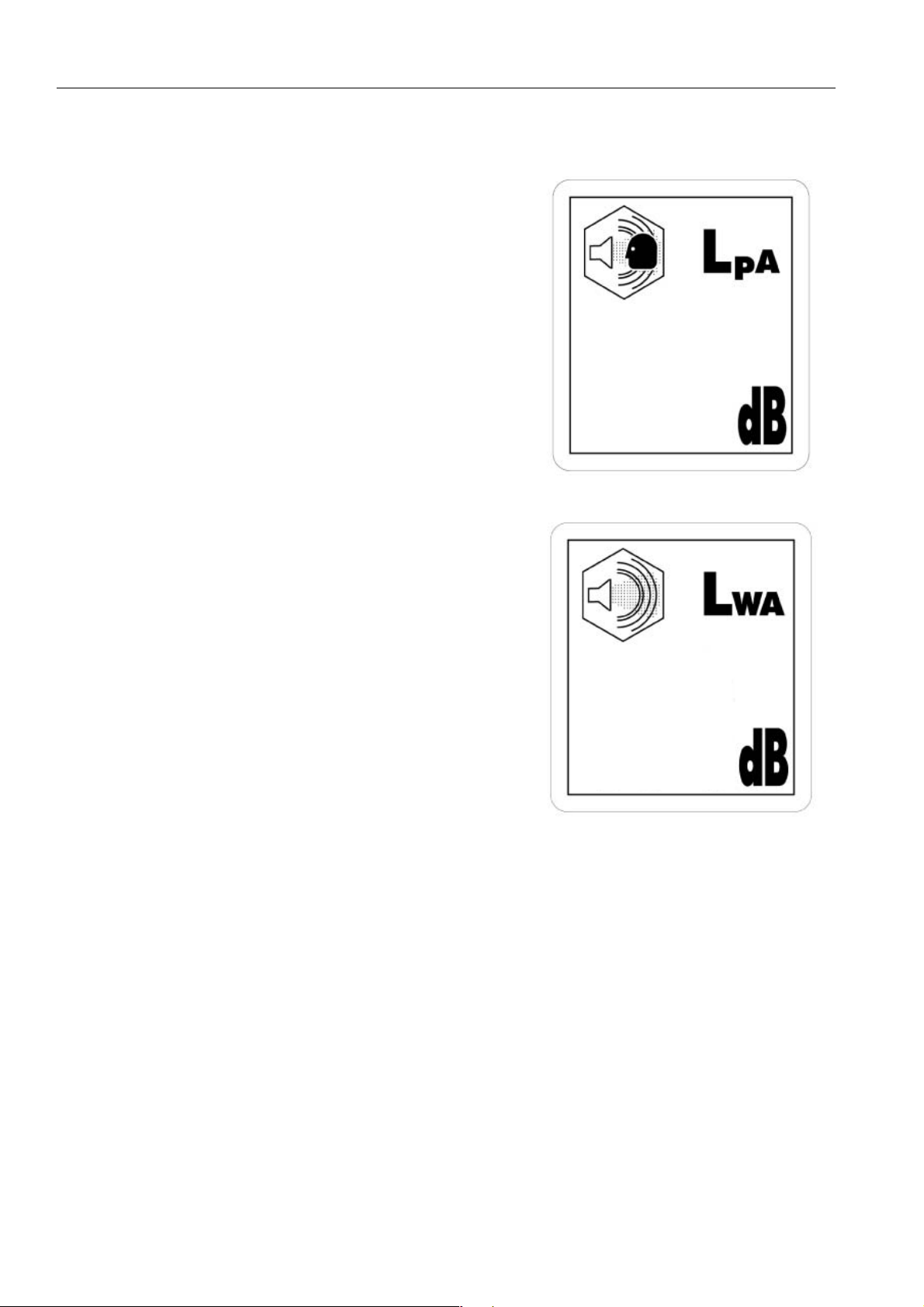
NOISE
● Sound pressure level at the operator’s station, measured
according to ISO6396 (Dynamic test method, simulated working cycle).
71
● Sound power level emitted. This is the gu aranteed value as
specified in the European directive 2000/14/EC
VIBRATION
● The weighted root mean square acceleration value to whic h
the operator’s arms are subjected does not exceed 2.5 m/s²
● The weighted root mean square acceleration value to whic h
the operator’s body is subjected was measured at 0.5m/s²
These results were obtained by accelerometers during trench digging.
● This machine is equipped with an operators seat which meets
the requirements of ENISO 7096.
101
6 PW160-7H VEAM390100
Page 7

FOREWORD SAFETY INFORMATION
EMERGENCY STEERING
This machine is equipp ed with an emergency steering system
and complies to ISO 501 0 (BSEN 12643) . In the a dvent o f failure
of the source of power for the steering system (eng ine failure)
whilst travelli ng, the machine can be steer ed allowing the
machine to be safely stopped.
In such a case, the effort required at the steering wheel and the
number of turns to steer the machine will increa se. To confirm
function of emergency steering system, raise the front wheels off
the ground (using the work equipment) and with the engine off,
turn the steering wheel and check movement of the wheels.
EMERGENCY BRAKING
This machine is equipped with an emergency braking system and
complies to ISO 3450. In t he advent of failure of the sou rce of
power for the b raki ng s ystem ( en gin e failure) whilst tr av el li ng, the
brakes can be actuated from stored energy in the accumulators to
bring the machine safely to a stop.
In such a case, seven brake applications can be made before
exhausting the energy in the accumulators. In the advent of service brake failure, the park brake can be used as an emergency
brake to bring the machine to a stop.
PW160-7H VEAM390100 7
Page 8

INTRODUCTION FOREWORD
INTRODUCTION
INTENDED USE
This Komatsu HYDRAULIC EXCAVATOR is designed to be used
mainly for the following work:
● Digging
● Smoothing work
● Ditching work
● Loading work
See the section see "WORK POSSIBLE USING HY DRAULIC EXCAVATOR (185)" for further details
FEATURES
● This Komatsu HYDRAULIC EXCAVATOR is equipped with
various controls based on an advanced electronics system.
● The monitor panel greatly facilitates daily maintenance and
self-diagnosis.
● Working mode & travel speed are selectable.
● Digging and lifting force can be incr eased by light -touch con-
trol. (For details, see operation section.)
● Adjustable wrist co ntrol levers make operation s smooth and
easy.
● Fresh filtered air conditioner assures comfortable operation.
● Low noise level and smart urban style design and colouring.
● Superb operation per formance provided by powerful engine
and high-performance hydraulic pump.
● Low fuel consumptio n contro lled by an ele ctronic contr ol sy s-
tem provides an environment-friendly machine.
● Sophisticated driv e train provides fast and smooth tr avelling
on the highway and off road.
8 PW160-7H VEAM390100
Page 9

FOREWORD INTRODUCTION
BREAKING IN YOUR NEW MACHINE
Your Komatsu machi ne h as been thorou ghly adj uste d and tes ted
before shipment.
However, operating the machine under severe cond itions at the
beginning can adversely affect the performance and shorten the
machine life.
Be sure to break in the machine for the initial 100 hours (as indicated by the hour meter.)
During breaking in:
● Idle the engine for 5 minutes after starting it up.
● Avoid operation with heavy loads or at high speeds.
● Sudden starting or acceleration, unnecessarily abrupt braking
and sharp turning should be avoided except in cases of emergency.
Additionally for the first 20 hours
● Avoid operating engine for prolonged periods at constant
speed (including idle.)
● Avoid high speed travelling for p eriods of more than 5 min-
utes.
Pay particular attention to oil pressure and temperature indicators
& check coolant and oil levels frequently during breaking in.
The precautions given in thi s manual for o perating, mainte nan ce,
and safety procedures are only those that apply when this product
is used for the specified purpose. If the machine is used for a purpose that is not listed in this manual, Komatsu cannot bear any
responsibility for safety. All consideration of safe ty i n such oper ations is the responsibility of the user.
Operations that are prohibited in this manual must never be carried out under any circumstances.
PW160-7H VEAM390100 9
Page 10
LOCATIONS OF PLATES, TABLE TO ENTER SERIAL NO. AND DISTRIBUTOR FOREWORD
LOCATIONS OF PLATES, TABLE TO ENTER SERIAL NO. AND DISTRIBUTOR
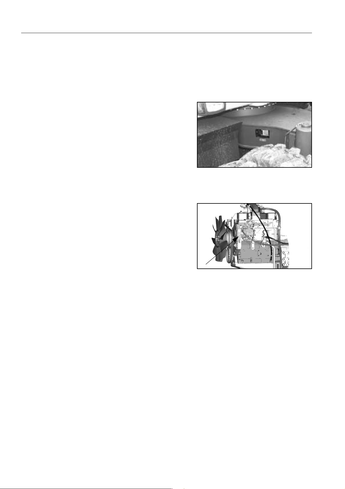
MACHINE SERIAL NO. PLATE POSITION
On the front right of the undercarriage
ENGINE SERIAL NO. PLATE POSITION
On the gear case front corner.
TABLE TO ENTER SERIAL NO. AND DISTRIBUTOR
Machine serial No.:
Engine Serial No.:
Product Identification Number.
Manufacturer’s name: Komatsu Hanomag GmbH.
Address
Hanomagstr. 9
30449 Hannover
Germany
Distributor
Address
Phone
10 PW160-7H VEAM390100
Page 11
FOREWORD LOCATIONS OF PLATES, TABLE TO ENTER SERIAL NO. AND DISTRIBUTOR
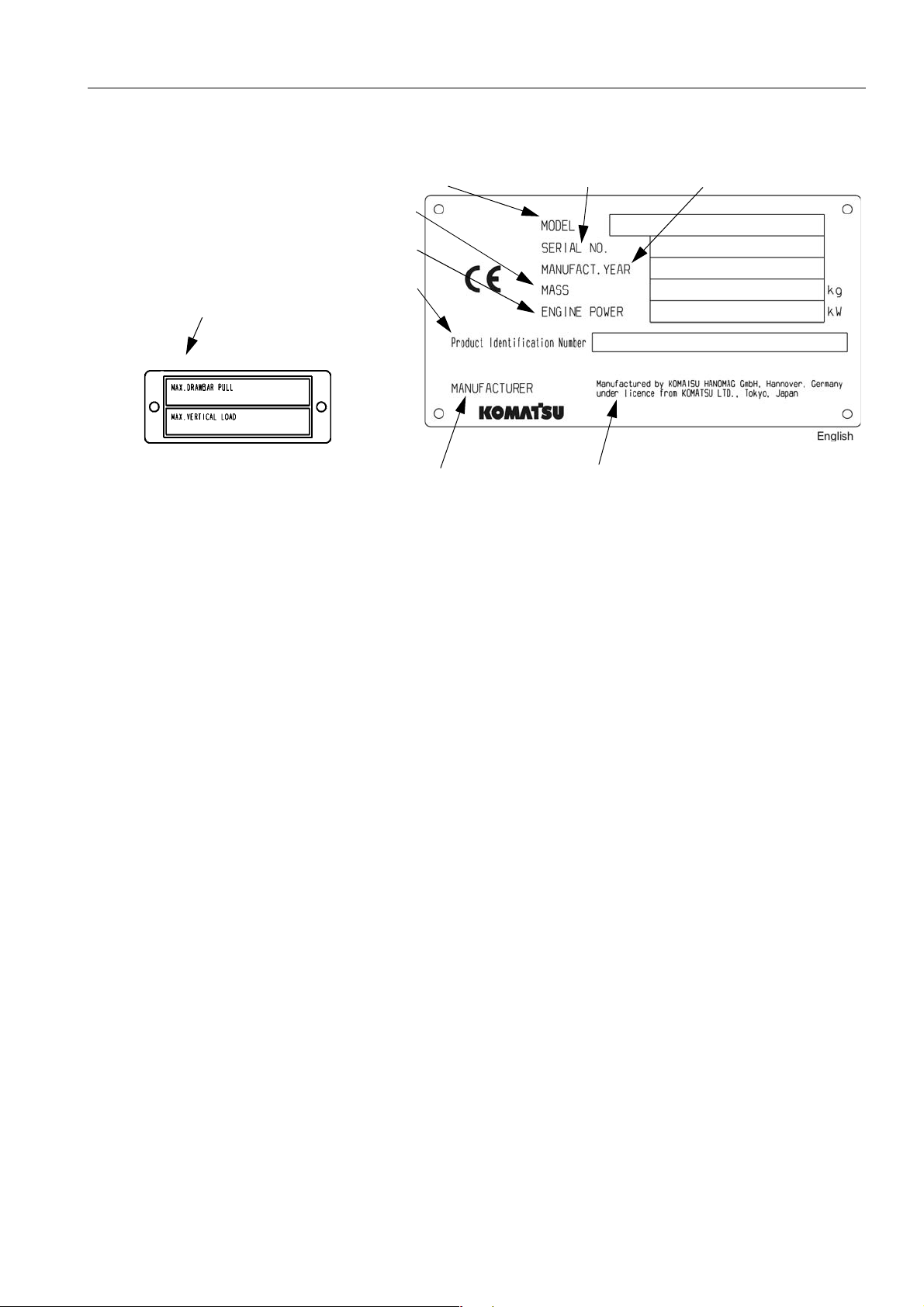
MACHINE SERIAL PLATES
STANDARD SERIAL PLA TE
Max. drawbar pull
Identification Number
Weight
Engine power
Product
Model
Manufactured by Komatsu Hanomag GmbH, Hannover, Germany
under License from Komatsu Ltd.
Serial num ber
Manufacturing year
PW160-7H VEAM390100 11
Page 12

LOCATIONS OF PLATES, TABLE TO ENTER SERIAL NO. AND DISTRIBUTOR FOREWORD
12 PW160-7H VEAM390100
Page 13

CONTENTS
FOREWORD.........................................................................................................3
FOREWORD .................... ................................. ................................ ................................ ...................................... 4
SAFETY INFORMATION ........................................................................................................................................ 5
SAFETY MESSAGES ...................... ....... ...... ................................................................................................ 5
NOISE .................... .......................... .......................... .......................... ......................................................... 6
VIBRATION ................................................................................................................................................... 6
EMERGENCY STEERING ........................................................................................................................... 7
INTRODUCTION ..................................................................................................................................................... 8
INTENDED USE ........................................................................................................................................... 8
FEATURES ................... .......................... .......................... ......................... ................................................... 8
BREAKING IN YOUR NEW MACHINE ........................................................................................................ 9
LOCATIONS OF PLATES, TABLE TO ENTER SERIAL NO. AND DISTRIBUTOR ........................................... 10
MACHINE SERIAL NO. PLATE POSITION ................................................................................................ 10
ENGINE SERIAL NO. PLATE POSITION .................................................................................................. 10
TABLE TO ENTER SERIAL NO. AND DISTRIBUTOR .............................................................................. 10
MACHINE SERIAL PLATES ......................... ....... ............................................. ...... .................................... 11
SAFETY.............................................................................................................19
GENERAL PRECAUTIONS .......................................... ...... ....... ...... ...... ....... ...... ....... ...... .................................... 20
PRECAUTION DURING OPERATION ................................................................................................................. 27
BEFORE STARTING ENGINE ................................................................................................................... 27
OPERATING MACHINE ............................................................................................................................. 28
TRANSPORTATION .................. ................................ ................................ ................................................. 35
BATTERY ................................................................................................................................................... 36
TOWING ..................................................................................................................................................... 37
BUCKET WITH HOOK OR BUCKET LINK WITH LIFTING EYE ............................................................... 38
HANDLING OF FLUIDS .............................................................................................................................. 40
PRECAUTIONS FOR MAINTENANCE ......................... ............................................. ...... ....... ...... ....... ................ 42
BEFORE CARRYING OUT MAINTENANCE ............................................................................................. 42
DURING MAINTENANCE ........................................................................................................................... 45
POSITION FOR ATTACHING SAFETY LABELS ................................................................................................ 48
POSITION FOR ATTACHING SAFETY LABELS ................................ ...... .............................................. ... 48
LIFTING CAPACITY CHART PW160-7H ............................................................................................................. 56
ONE PIECE BOOM Lift capacity tables ...................................................................................................... 56
TWO PIECE BOOM Lift capacity tables ..................................................................................................... 62
OVERLOAD CAUTION ............................................................................................................................... 68
PW160-7H VEAM390100 13
Page 14

OPERATION....................................................................................................... 69
GENERAL VIEW ........................................................................................... ...... ................................................. 70
GENERAL VIEW OF MACHINE ............................................. ...... ....... ...... ....... ...... .................................... 70
GENERAL VIEW OF CONTROLS AND GAUGES ..................................................................................... 71
EXPLANATION OF COMPONENTS .................................................................................................................... 72
MACHINE MONITOR ................................................ ....... ...... ...... .............................................................. 72
BASIC CHECK ITEMS ............................ ...... ....... ...... ............................................. ....... ...... ....................... 75
SWITCHES ......................................................................................................................................................... 103
CONTROL LEVERS, PEDALS .......................................................................................................................... 111
FRONT WINDOW ..................................................................................................................................... 117
EMERGENCY EXIT FROM OPERATOR'S CAB ..................................................................................... 121
DOOR LOCK ............................................................................................................................................ 122
CAP, COVER WITH LOCK ....................................................................................................................... 123
FUSE ........................................................................................................................................................ 124
LUGGAGE TRAY ................ ....... ...... ....... ...... ....... ...... ....... ...... ...... ....... ..................................................... 125
ASHTRAY ..................... .......................................................... .................................................................. 125
CUP HOLDER .......................................................................................................................................... 125
HOT AND COOL BOX .............................................................................................................................. 125
CAB RADIO .............................................................................................................................................. 126
POWER PICK-UP PORT .......................................................................................................................... 126
HANDLING AIR CONDITIONER .............................................................................................................. 127
FUSIBLE LINK .......................................................................................................................................... 140
CONTROLLER ......................................................................................................................................... 141
TOOL BOX (CHASSIS) ............................................................................................................................ 141
REFUELLING PUMP ................................................. ....... ............................................. ...... .... ................. 141
WARNING LAMPS ................................................................................................................................... 143
HANDLING ACCUMULATORS ................................................................................................................ 144
OPERATION .................... ................................. ................................ .................................................................. 145
CHECK BEFORE STARTING ENGINE .................................................................................................... 145
OPERATIONS AND CHECKS BEFORE STARTING ENGINE ......................................................................... 156
...................................... ................................................................ ............................................................ 157
STARTING ENGINE ................................................................................................................................. 158
MOVING MACHINE OFF .......................................................................................................................... 167
STEERING ................................................................................................................................................ 170
TRAVELLING ON PUBLIC HIGHWAY ..................................................................................................... 171
STOPPING & PARKING ........................................................................................................................... 172
SWINGING (Slewing the upper carriage) ................................................................................................. 174
OPERATION OF WORK EQUIPMENT .................................................................................................... 175
WORKING MODE SELECTION ............................................................................................................... 177
PROHIBITIONS FOR OPERATION ............................................. ....... ...... ....... ...... ....... ...... ....... ...... ........ 179
PRECAUTIONS FOR OPERATION ......................................................................................................... 180
RECOMMENDATIONS FOR TRAVELLING ............................................................................................. 182
PRECAUTIONS WHEN TRAVELLING UP OR DOWN HILLS ................................................................. 183
Page 15

HOW TO ESCAPE FROM MUD ............................................................................................................... 184
WORK POSSIBLE USING HYDRAULIC EXCAVATOR ........................................................................... 185
REPLACEMENT AND INVERSION OF BUCKET .................................................................................... 187
STOPPING ENGINE ................................................................................................................................. 189
CHECK AFTER FINISHING WORK ......................................................................................................... 189
CHECK AFTER STOPPING ENGINE ................................................................................................................ 190
LOCKING ...................... ................................ ................................ ................................. ........................... 190
OVERLOAD WARNING DEVICE ............................................................................................................. 190
HANDLING THE WHEELS ....................................................................................................................... 190
TRANSPORTATION ........................................................................................................................................... 195
LOADING, UNLOADING WORK ............ ...... ....... ...... ............................................. ....... ...... ..................... 195
PRECAUTIONS FOR LOADING .............................................................................................................. 197
PRECAUTIONS FOR TRANSPORTATION ............................................................................................. 200
TRAVELLING POSTURE ......................................................................................................................... 202
COLD WEATHER OPERATION ........................................................................................................................ 204
PRECAUTIONS FOR LOW TEMPERATURE .......................................................................................... 204
PRECAUTIONS AFTER COMPLETION OF WORK ................................................................................ 206
AFTER COLD WEATHER ...................... ...... ....... ...... ............................................. ....... ...... ..................... 206
LONG-TERM STORAGE .................................................................................................................................... 207
BEFORE STORAGE ................................................................................................................................. 207
DURING STORAGE ................................................................................................................................. 207
AFTER STORAGE ........................... ....... ...... ....... ............................................. ...... ....... ...... ..................... 208
STARTING MACHINE AFTER LONG-TERM STORAGE ........................................................................ 208
TROUBLESHOOTING .................. ....... ...... ....... ...... ....... ...... ....... ...... ...... ....... ...... ....... ...... .................................. 209
PHENOMENA THAT ARE NOT FAILURES ............................................................................................. 209
METHOD OF TOWING MACHINE ........................................................................................................... 210
PRECAUTIONS ON PARTICULAR JOBSITES ....................................................................................... 210
DISCHARGED BATTERY ........................................................................................................................ 211
OTHER TROUBLE ................................................................................................................................... 215
MAINTENANCE ............................................................................................... 221
GUIDES TO MAINTENANCE ............................................................................................................................. 222
OUTLINE OF SERVICE ...................................................................................................................................... 225
OUTLINE OF OIL, FUEL, COOLANT ....................................................................................................... 225
OUTLINE OF ELECTRIC SYSTEM .......................................................................................................... 228
OUTLINE OF HYDRAULIC SYSTEM ....................................................................................................... 229
WEAR PARTS LIST ........................................................................................................................................... 231
USE FUEL, COOLANT AND LUBRICANTS ACCORDING TO AMBIENT TEMPERATURE .......................... 232
PROPER SELECTION OF FUEL, COOLANT AND LUBRICANTS ......................................................... 232
PW160-7H VEAM390100 15
Page 16

USE FUEL, COOLANT AND LUBRICANTS ACCORDING TO AMBIENT TEMPERATURE CONT. .............. 234
STANDARD TIGHTENING TORQUES FOR BOLTS AND NUTS ..................................................................... 236
INTRODUCTION OF NECESSARY TOOLS ............................................................................................ 236
TIGHTENING TORQUE SPECIFICATIONS ...................................................................................................... 237
TIGHTENING TORQUE LIST ................................................................................................................... 237
PERIODIC REPLACEMENT OF SAFETY CRITICAL PARTS .......................................................................... 238
SAFETY CRITICAL PARTS .......................... ....... ...... ....... ...... ...... ....... ...... ....... ...... ....... ...... ....... . ............. 239
MAINTENANCE SCHEDULE CHART ............................................................................................................... 240
KEY TO LUBRICATION POINTS ............................................................................................................. 244
SERVICE PROCEDURE .................................................................................................................................... 246
INITIAL 50 HOURS SERVICE .................................................................................................................. 246
CHECK AND TIGHTEN WHEEL NUTS ................................................................................................... 246
INITIAL 250 HOURS SERVICE ................................................................................................................ 246
WHEN REQUIRED ................................................................................................................................... 247
CHECKING COOLANT LEVEL ................................................................................................................ 255
CHECK AND TIGHTEN WHEEL NUTS ................................................................................................... 258
CHECK ELECTRICAL INTAKE AIR HEATER .......................................................................................... 258
CHECK ALTERNATOR ............................................................................................................................ 258
REPLACE BUCKET SIDE CUTTERS ...................................................................................................... 259
REPLACE BUCKET TEETH ..................................................................................................................... 260
ADJUST BUCKET CLEARANCE ..................................... ...... ...... ....... ...... ....... ...... ....... ........................... 264
CHECK WINDOW WASHER FLUID LEVEL, ADD FLUID ....................................................................... 265
CHECK AND ADJUST AIR CONDITIONER ............................................................................................. 266
CHECK BEFORE STARTING .................................................................................................................. 267
CHECK COOLANT LEVEL, ADD WATER ............................................................................................... 267
EVERY 50 HOURS ................................................................................................................................... 272
EVERY 100 HOURS SERVICE ................................................................................................................ 273
EVERY 250 HOURS MAINTENANCE ...................................................................................................... 279
EVERY 500 HOURS SERVICE ................................................................................................................ 285
EVERY 1000 HOURS SERVICE .............................................................................................................. 292
EVERY 2000 HOURS SERVICE .............................................................................................................. 299
EVERY 4000 HOURS SERVICE .............................................................................................................. 301
EVERY 5000 HOURS SERVICE .............................................................................................................. 302
SPECIFICATIONS............................................................................................305
SPECIFICATIONS ........................ ................................................................. ..................................................... 306
1 - PIECE BOOM ...................................................................................................................................... 307
2 - PIECE BOOM ...................................................................................................................................... 308
WORKING RANGE: ONE PIECE BOOM ................................................................................................. 309
WORKING RANGE: TWO PIECE BOOM ................................................................................................ 310
Page 17

OPTIONS, ATTACHMENTS ............................................................................311
GENERAL PRECAUTIONS .......................................... ...... ....... ...... ...... ....... ...... ....... ...... .................................. 312
PRECAUTIONS RELATED TO SAFETY ................................................................................................. 312
PRECAUTIONS WHEN INSTALLING ATTACHMENTS .............................. ..................................................... 313
HANDLING BUCKET WITH HOOK ................................................................................................................... 315
CHECKING FOR DAMAGE TO BUCKET WITH HOOK .......................................................................... 315
PROHIBITED OPERATIONS ................................................................................................................... 315
PRECAUTIONS DURING OPERATIONS ................................................................................................ 315
MACHINES READY FOR ATTACHMENTS ...................................................................................................... 316
GENERAL LOCATIONS ............................................ ............................................. ....... ........................... 316
HANDLING THE CLAMSHELL BUCKET ................................................................................................. 318
OPERATION ................. ................................ ................................ ................................. ........................... 320
METHOD FOR RELEASING PRESSURE IN CONTROL CIRCUIT OF MACHINES EQUIPPED WITH
ACCUMULATOR ...................................................................................................................................... 323
LONG-TERM STORAGE .......................................................................................................................... 323
INTRODUCTION OF ATTACHMENTS AND EXTENDING MACHINE SERVICE LIFE .................................... 324
HYDRAULIC BREAKER ........................................................................................................................... 324
POWER RIPPER ...................................................................................................................................... 327
FORK GRAB ............................................................................................................................................. 328
GRAPPLE BUCKET ................................................................................................................................. 329
SCRAP GRAPPLE ..................... ...... ....... ...... ....... ...... ....... ...... ............................................. ..................... 330
CRUSHER & SMASHER .......................................................................................................................... 332
HYDRAULIC PILE DRIVER ...................................................................................................................... 333
HYDRAULIC EXCAVATOR WITH MULTIPURPOSE CRANE ................................................................. 334
INDEX ................................................................................................................................................................. 343
PW160-7H VEAM390100 17
Page 18

18 PW160-7H VEAM390100
Page 19

SAFETY
WARNING
Read and follow all safety precautions. Failure to do so may
result in serious injury or death.
This safety secti on also contains precautions fo r optional eq uipment and attachments.
PW160-7H VEAM390100 19
Page 20
GENERAL PRECAUTIONS SAFETY
WARNING: For reasons of safety, always follow these safety precautions.
GENERAL PRECAUTIONS
SAFETY RULES
● ONLY trained and authorised personnel can operate and
maintain the machine.
● Follow all safety rules, precautions and instructions when
operating or performing maintenance on the machine.
● When working with ano the r o perat or or a p er so n on work si te
traffic duty, be sure all personnel understand all han d signals
that are to be used.
SAFETY FEATURES
● Be sure all guards and covers are in their proper position.
Have guards and covers repaired if damaged.
● Use safety features such as safety lock lever at all times.
● NEVER remove any safety features . ALWAY S keep them in
good operating condition.
● Always wear safety belt when operating machine.
● Improper use of safety features could result in serious bodily
injury or death.
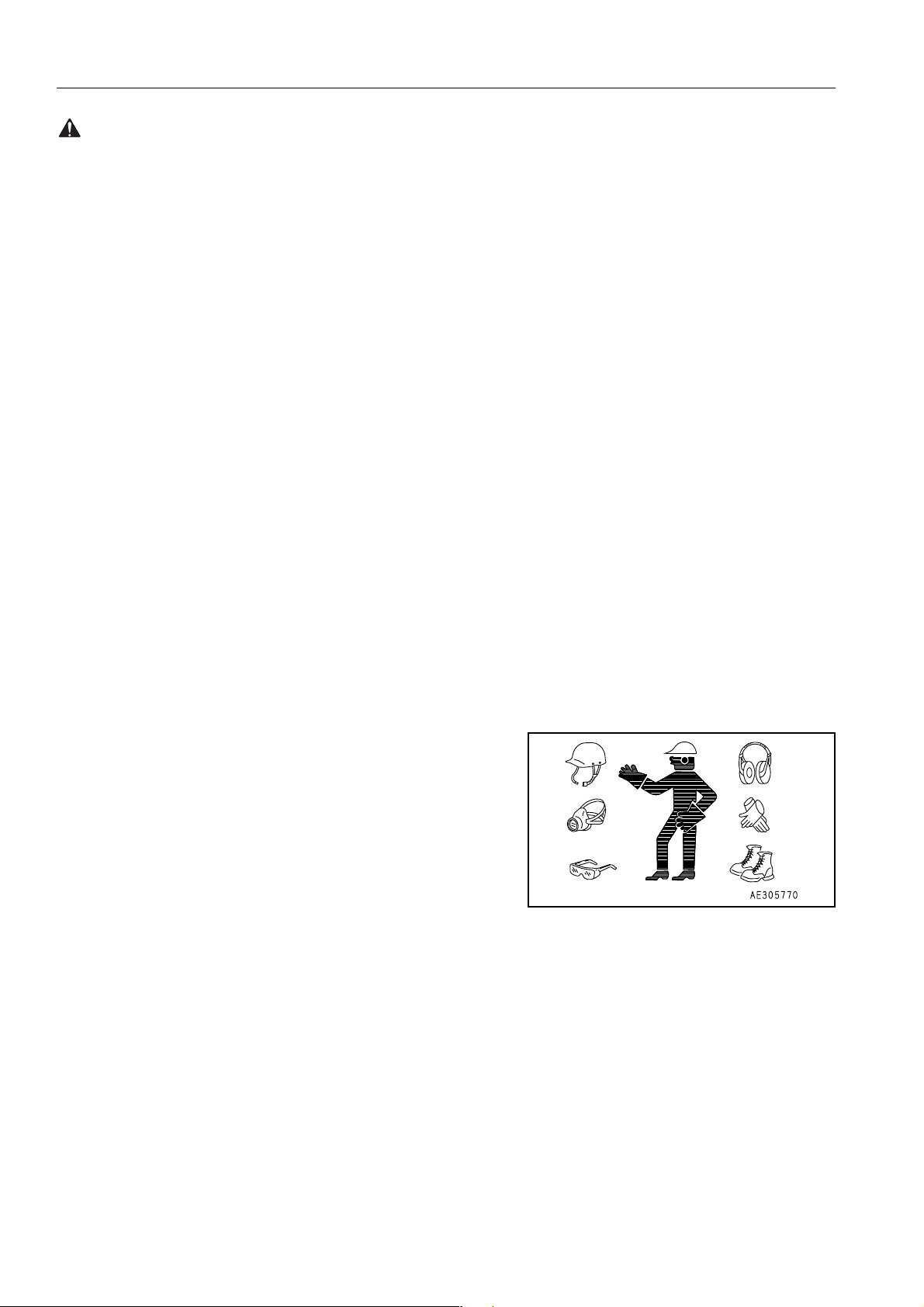
CLOTHING AND PERSONAL PROTECTIVE ITEMS
● Avoid loose clothin g, jew eller y, and loose long h air. They can
catch on controls or in movin g parts and cause serio us injury
or death. Also, do not wear oily clothes because they are
flammable.
● Wear a hard hat, safety glasses, safety shoes, mask or
gloves when operating or maintaining the machine. Always
wear safety goggles, hard hat and heavy gloves if your job
involves scattering metal chips or minute materials, this is so
particularly when driving pins with a hammer and when cleaning the air cleaner element with compressed air.
Check also that there is no one near the machine.
Driving in pins, see"REPLACEMENT AND INVERSION OF
BUCKET (187)"
Cleaning of air cleaner elemen t, see "WHE N REQUIRED
(247)" in service procedure.
UNAUTHORISED MODIFICATION
● Any modification made without authorisation from Komatsu
can create hazards.
● Before making a modi fication, consult your Ko matsu distribu -
tor. Komatsu will not be responsible for an y injury or damage
caused by any unauthorised modific atio n.
20 PW160-7H VEAM390100
Page 21
SAFETY GENERAL PRECAUTIONS
R
WARNING: Failure to follow these safety precautions may lead to a serious accident.
ALWAYS APPLY (RA ISE) SAFETY LOCK LEVER WHEN
LEAVING OPERATOR’S SEAT
● When standing up from the operator ’s seat, always raise the
safety lock lever to the LOCK position. If you accidentally
touch the travel or swing lever when they are not locked, the
machine may suddenly move and caus e serious injury or
damage.
EMARK
In certain conditions it may be possible for the safety lock
lever to contact the left hand arm rest on the operator seat.
to avoid this , alway s ensure that the left ha nd arm r est is st owed
LOCK
UNLOCK
in the fully up position before operating the safety lock lever.
● When leaving the machine, lower the work e quipment com-
pletely to the ground, set the safety lock lever to the LOCK
position, then stop the engine and use the key to lock the
machine. Always take the key with you.
WARNING
If the control lever is touche d by accident, the wo rk equipment or the machine may move suddenly, and this may lead
to a serious accident. Befo re le aving t he o perat or’s compartment, always raise the safety lock lever to lock the work
equipment controls.
ALWAYS CHOCK THE WHEELS BEFORE GOING UNDER
THE MACHINE
q The chocks are located in the left hand toolbox (A) on the
machine.
A
PW160-7H VEAM390100 21
Page 22
GENERAL PRECAUTIONS SAFETY
WARNING: For reasons of safety, always follow these safety precautions.
MOUNTING AND DISMOUNTING
● NEVER jump on or off the mac hine. NEVER get on or off a
moving machine.
● When mounting or dismounting, always face the machine and
A
use the handrails (A), machine or chassis steps (B).
● Do not hold any control levers when getting on or off the
machine.
● Ensure safety by al ways ma intaining at leas t thre e-point c on-
tact of hands and feet with the handrails, steps or wheels.
● Always remove an y oil or mu d from the han drails, steps and
track shoes. If they are damaged, repair them and tighten any
loose bolts.
● If grasping the door handrail when mounting or dismounting
or moving on the chassis steps, op en and lock the door
securely in the open posi tion. Othe rwise, the door may move
suddenly, causing you to lose balance and fall.
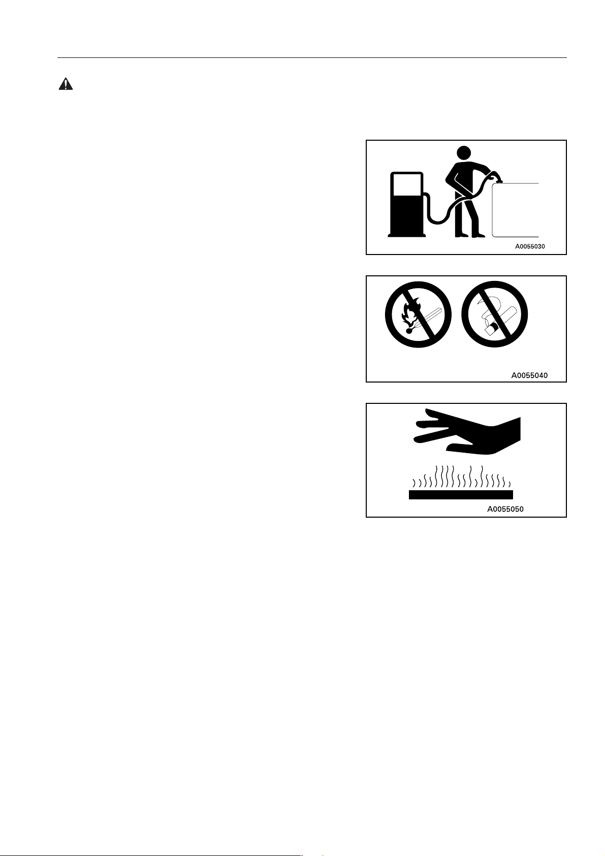
FIRE PREVENTION FOR FUEL AND OIL
Fuel, oil, and antifreeze can be ignite d by a fla me. Fuel is particularly FLAMMABLE and can be HAZARDOUS.
● Keep flames away from flammable fluids.
● Stop the engine and do not smoke when refuelling.
B
A
B
22 PW160-7H VEAM390100
Page 23
SAFETY GENERAL PRECAUTIONS
WARNING: Failure to follow these safety precautions may lead to a serious accident.
● Tighten all fuel and oil caps securely.
● Refuelling and o iling should be carried out in well ventilated
areas.
● Keep oil and fuel in a secure place and do not allow unautho-
rised persons to enter.
PRECAUTIONS WHEN HANDLING AT HIGH TEMPERATURES
● Immediately after operations are stopped, the engine coolant,
engine oil, and hydraulic oil are at high temperatures, and are
still under pressure. Attempting to remove the cap, drain the
oil or water, or replace the filters may lead to s erious burns.
Always wait for the temperature to go down, and follow the
specified procedures when carrying out these operations.
● To prevent hot water from spurting out:
1. Turn engine off.
2. Allow water to cool.
3. Slowly loosen cap to relieve pressure before removing.
● To prevent hot oil from spurting out:
1. Turn engine off.
2. Allow oil to cool.
3. Slowly loosen cap to relieve pressure before removing.
MACHINES FITTED WITH WHEELS
Never perform any repair work or modifications to wheel rims
while the tyres are fitted, and never apply heat in the vicinity of the
tyres.
PW160-7H VEAM390100 23
Page 24
GENERAL PRECAUTIONS SAFETY
WARNING: For reasons of safety, always follow these safety precautions.
ASBESTOS DUST HAZARD PREVENTION
Asbestos dust can be HAZARDOUS to your health if it is inhaled.
Your Komatsu machin e and genu ine Kom atsu spare parts do not
contain any asbestos. Use only genuine Komatsu spare parts. If
spare parts containing asbestos ar e used, th e followin g precautions must be observed:
● NEVER use compressed air for cleaning.
● Use water for cleaning to keep down the dust.
● Operate the machine with the wind to your back, wh enever
possible.
● Use an approved respirator if necessary.
CRUSHING OR CUTTING PREVENTION
Do not enter, or put your hand or arm or any other part of your
body between movable parts such as between the work equipment and cylinders, or between the machine and work equipment.
If the work equipment is operated, the clearance will change and
this may lead to serious damage or personal injury.
FIRE EXTINGUISHER AND FIRST AID KIT
● Know how to use fire extinguisher (if installed).
● Provide a first aid kit at the storage point.
● Know what to do in the event of a fire.
● Be sure you know the phon e numbe rs of pe rsons you s hould
contact in case of an emergency.
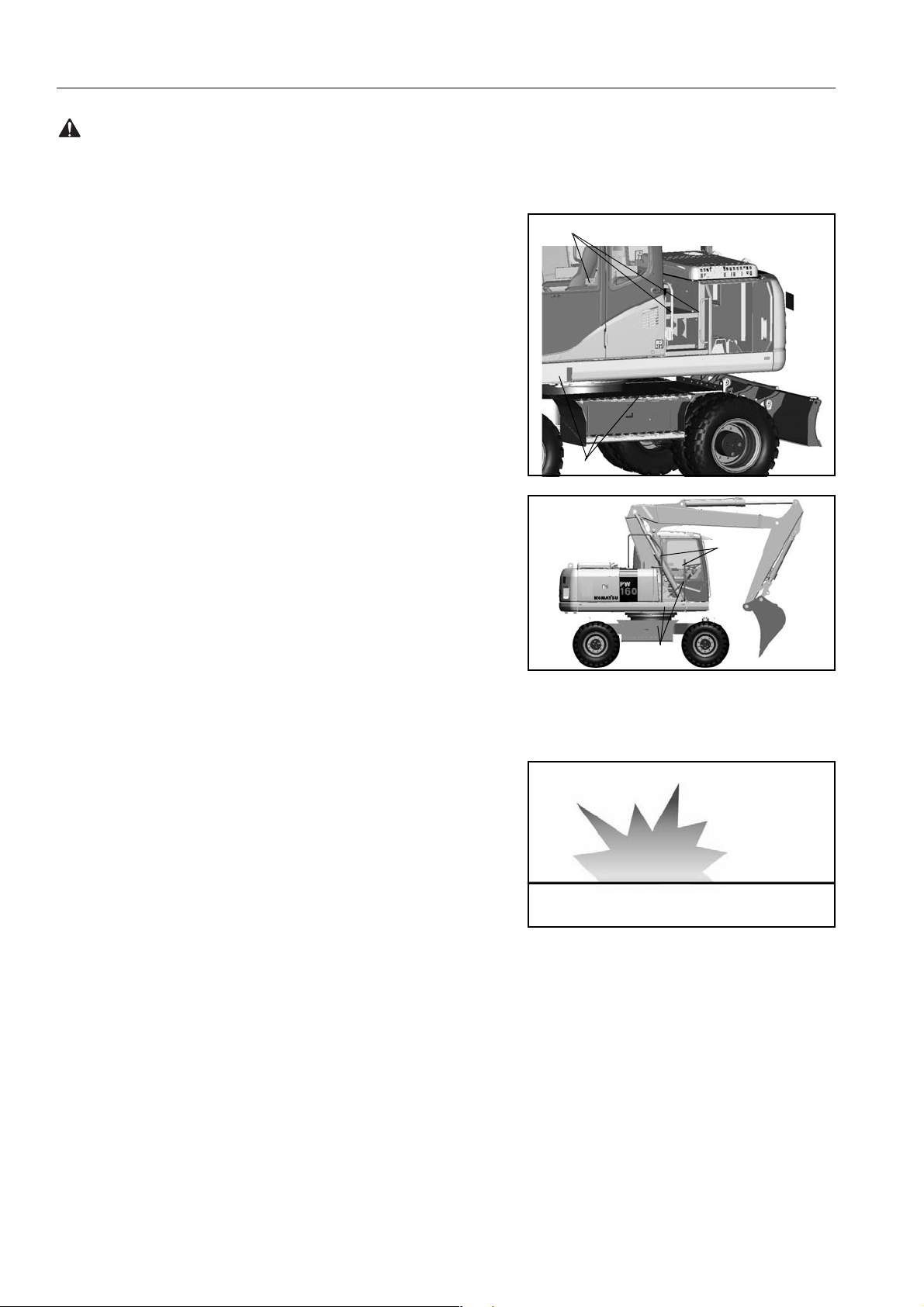
PROTECTION AGAINST FALLING OR FLYING OBJECTS
If there is any danger of falli ng or fly ing ob jects hitt ing the opera tor, install protective guards to protect the operator as required for
each particular situation.
● For work with breakers, install a front guard on the wind-
shield. Also, place a laminate coating sheet over the windshield.
● For demolition or shear work, install a front guard on the
windshield and a top guard on the cab. Also, place a laminate
coating sheet over the windshie ld.
24 PW160-7H VEAM390100
Page 25
SAFETY GENERAL PRECAUTIONS
WARNING: Failure to follow these safety precautions may lead to a serious accident.
● For work in mines, quarries, demolition, tunnels or other
places where there is danger of falling rocks, put FOPS (fall-
ing object protective structure) in place. Also, place a lami-
nate coating sheet over the windshield.
The above comments are made with regards to typical working
conditions. By all means you should put on other guards if
required by conditions at your particular site.
For details of safety gua rds, p lease contact yo ur Kom atsu distri butor.
Also, even for other types of work, if there is any danger of being
hit by falling or flying objects or of objects entering the operator’s
(B)
cab, select and install a guard that matches the working conditions.
(C)
(B): Top guard (C): Front guard
Be sure to close the front window before commencing work.
When carrying ou t the above operations , make sure to keep all
persons other tha n th e o per ato r outside t he ra nge of fall in g o r fly ing objects. Be particularly sure to maintain a proper distance
when carrying out shear operations.
PRECAUTIONS FOR ATTACHMENTS
● When installing and using an optional attachment, read the
instruction manual for the attachment and the information
related to attachments in this manual.
● Do not use attachments that a re not authorised by Koma tsu
or your Komatsu distributor. Use of unauthorised attachments
could create a safety problem and adversely affect the proper
operation and useful life of the machine.
● Any injuries, accidents, product failures resulting from the use
of unauthorised attachments wil l not be the re sponsibi lity of
Komatsu.
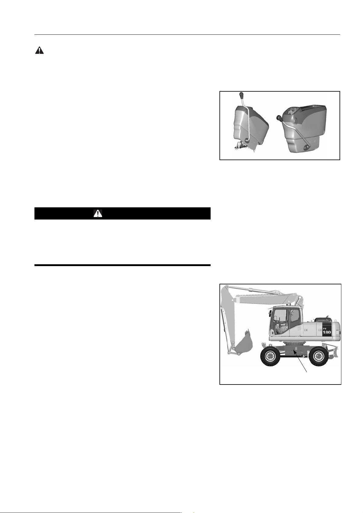
MACHINES WITH ACCUMULATOR
On machines equipped with an ac cumul ator, for a short time after
the engine is stoppe d, the work equi pment will lower under its
own weight when the work equipment control lever is shifted to
LOWER. After the engine is stopped, raise safety lock lever to the
LOCK position.
AB30052C
When releasing the pressure inside the work equipment circuit on
machines equipped with an ac cumulator, follow the procedure
given in the inspection and maintenance section.
Method of releasing pressure, see "HANDLING ACCUMU-
LATORS (144)"
The accumulator is filled with high-pressure nitrogen gas, and it is
extremely dangerou s if it is handled in the wron g way. Always
observe the following precaution s.
PW160-7H VEAM390100 25
Page 26
GENERAL PRECAUTIONS SAFETY
WARNING: For reasons of safety, always follow these safety precautions.
● Never make any hole in the accumulator or expose it to flame
or fire.
● Do not weld anything to the accumulator.
● When carrying out dis assembly or maintenan ce of the accu-
mulator, or when disposing of the accumulator, it is necessary
to release the gas from the accum ulator. A special bleed
valve is necessary for this operation, so please contact your
Komatsu distributor.
Gas in accumulator, see "HANDLING ACCUMULATORS
(144)"
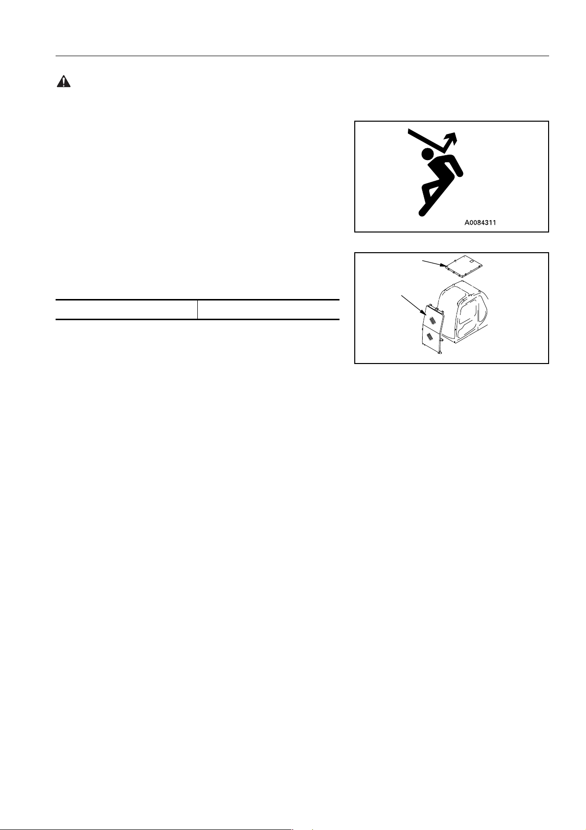
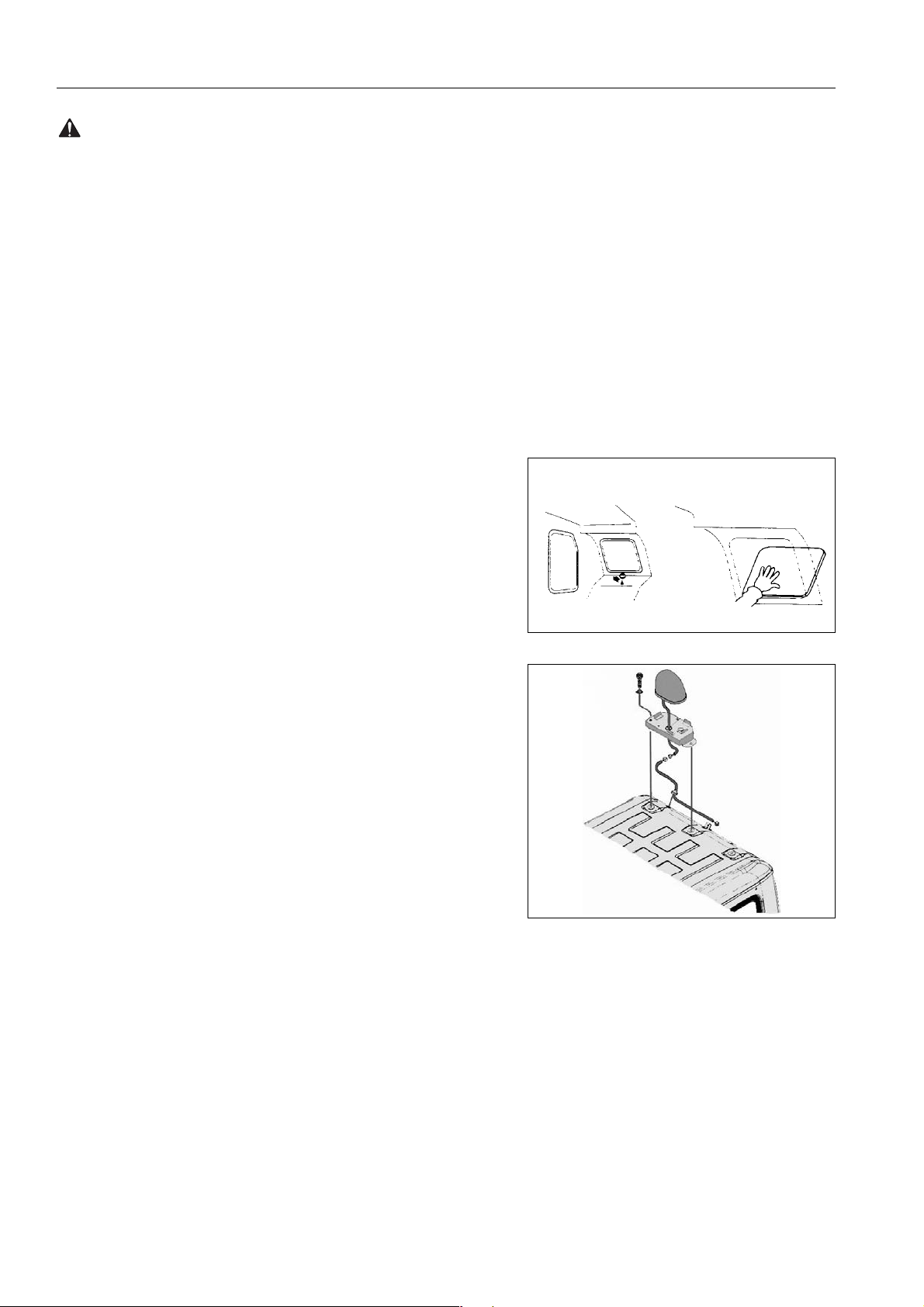
EMERGENCY EXIT
● When exit by normal means is prevented in an emergency
you can get out through the emergency exit (rear window).
● Pull the ring at the bottom of the window and remove strip.
This will allow you to push out glass.
ROTATING BEACON (Option)
● When the machine is operated on or beside a road, a rotating
beacon is required to avoid a traffic accident.
● Contact your Komatsu distributor to install beacon lamp.
ELECTROMAGNETIC INTERFERENCE
When this machin e is op erati ng cl ose to a sour ce of h igh el ectro magnetic interference, such as a radar station, some abnormal
phenomena may be observed.
● The display on the monitor panel may behave errati ca ll y.
● The warning buzzer may sound.
These effects do not s ignify a m alfuncti on and the machine wi ll
return to normal as soon as the source of interference is removed.
26 PW160-7H VEAM390100
Page 27
SAFETY PRECAUTION DURING OPERATION
WARNING: Failure to follow these safety precautions may lead to a serious accident.
PRECAUTION DURING OPERATION
BEFORE STARTING ENGINE
SAFETY AT WORKSITE
● Before starting the engin e, thoroughly check th e area for any
unusual conditions that could be dangerous.
● Before starting the engine, examine the terrain and soil condi-
tions of the work site. Determine the best and safest method
of operation.
● Make the slope as horizontal as possible before continuing
operations.
● If you need to operate on a street, p rotect pedestrians and
cars by designating a person for work site traffic duty or by
installing fences around the work site.
● If water lines, gas lines, and high- voltage electric al lines may
be buried under the work site, c ontact eac h uti lit y a nd id enti fy
their locations. Be careful not to sever or cut any of these
lines.
● Check the depth and flow of water before operating in water
or crossing a river. NEVER be in water which is in excess of
the permissible water depth.
Permissible water depth, see "PRECAUTIONS FOR
OPERATION (180)"
FIRE PREVENTION
● Thoroughly remove wood chips, leaves, paper and other
flammable things accumulated in the engine compartment.
They coul d cause a fir e.
● Check fuel, lubrication, and hydraulic systems for leaks. Have
any leaks repaired. Wipe up any excess oil, fuel or other flam-
mable fluids.
Check point, see "WALK-AROUND CHECK (145)"
● Be sure a fire extinguisher is present and working.
IN OPERATOR’S CAB
● Do not leave tools or spare parts lying around in the opera-
tor’s compartment. They may damage or break the control
levers or swit ches. Always put them in the t ool box on the
undercarriage.
● Keep the cab f loor, controls, st eps and handrails free of o il,
grease, snow, and excess dirt.
PW160-7H VEAM390100 27
Page 28
PRECAUTION DURING OPERATION SAFETY
WARNING: For reasons of safety, always follow these safety precautions.
VENTILATION FOR ENCLOSED AREAS
If it is nece ssary to s tart th e eng ine w ithin an enc losed area, pro vide adequate ventil ation. Exhaust fum es from the e ngine can
KILL.
PRECAUTIONS FOR MIRRORS, WINDOWS AND LIGHTS
● Remove all dirt from the surface of the windows and lights to
ensure that you can see well.
● Adjust the rear v iew mirror s so that yo u can see clearly fr om
the operator’s seat, and always keep the su rface of the mirrors clean. If any glass is broken, replace it with a new part.
● Check that the head lamps and working lamps are installed to
match the operating conditions. Check also that they light up
properly.
OPERATING MACHINE
WHEN STARTING THE ENGINE
● Walk around for machine again just before mounting it, to
check for people and objects that might be in the way.
● NEVER start the engine if a warning tag has been attached to
the wrist control.
● Before starting the engine, sound the horn as an alert.
● Start and operate the machine only while seated.
● Do not allow anyone other than the operator to ride in the cab
or on the machine body.
● For machines equipped wit h a reverse alarm buzz er, check
that the warning device operates correctly.
CHECK DIRECTION BEFORE STARTING MACHINE
Before operating the travel pedal, check the direction of the under
carriage.
If the fixed axle is at the front, the forward/neutral/reverse lever
and steering will function in the opposite direction.
A Fixed axle
B Oscillating axle
Travel operations, see "MOVING MACHINE OFF (167)"
B
A
28 PW160-7H VEAM390100
Page 29
SAFETY PRECAUTION DURING OPERATION
WARNING: Failure to follow these safety precautions may lead to a serious accident.
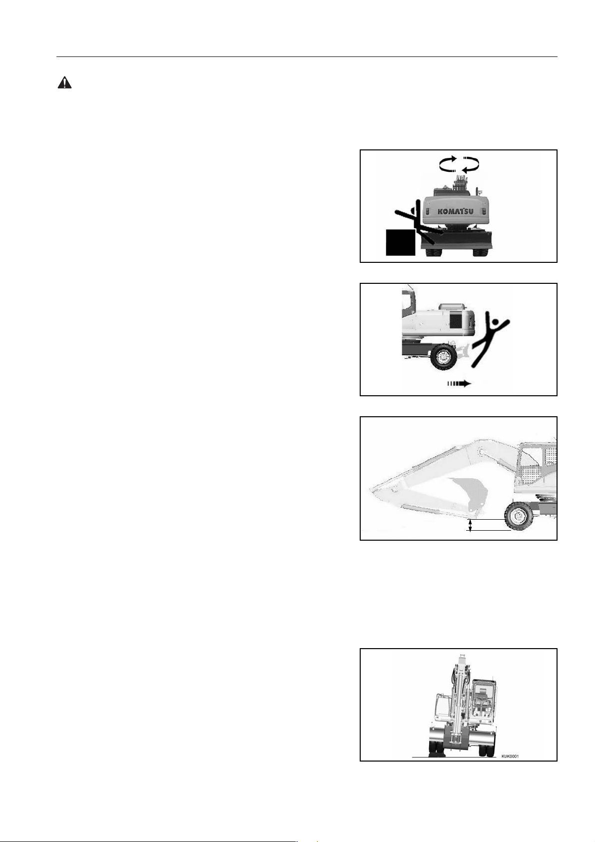
CHECK THAT NO ONE IS IN THE AREA BEFORE SWINGING
OR TRAVELLING IN REVERSE
● Always position a signalman when operating in dangerous
places or places where the view is not clear.
● Make sure that no one comes inside the swing radius or
direction of travel.
● Before starting to mov e, sound the horn or give a signa l to
warn people not to come close to the machine.
● Make use of all mirrors to ensure that the area around the
machine is clear.
● There are blind spots behind the machine, so if necessary,
swing the upper structure to check that there is no one behind
the machine before travelling in reverse.
PRECAUTIONS WHEN TRAVELLING
● Fold in the work equipment as shown in the diagram, and
keep it at a height of 40-50 cm from the ground level before
starting to travel.
● Before travelling on pu blic roads, fully rais e dozer blade and
outriggers, lock the outriggers in position with the safety pin,
lock the bucket and arm cylinder with isolation val ves, and
insert swing lock pin.
For details, see "TRAVELLING ON PUBLIC HIGHWAY
(171)"
● When travelling on p ublic roads the safety lo ck lever should
be down (UNLOCKED) and lock lever switc h engaged. This
prevents operation of the control lever s .
● When travelling on rough ground, travel at low speed, and
avoid sudden changes in direction.
● Avoid travelling over obstacles as far as possible. If the
machine has to travel over an obstacle, k eep the wor k equip-
ment as close to the ground as possible and travel at low
speed. Never travel over obstacles which make the machine
tilt strongly (10° or more).
40 - 50cm
INCORRECT
PW160-7H VEAM390100 29
Page 30
PRECAUTION DURING OPERATION SAFETY
WARNING: For reasons of safety, always follow these safety precautions.
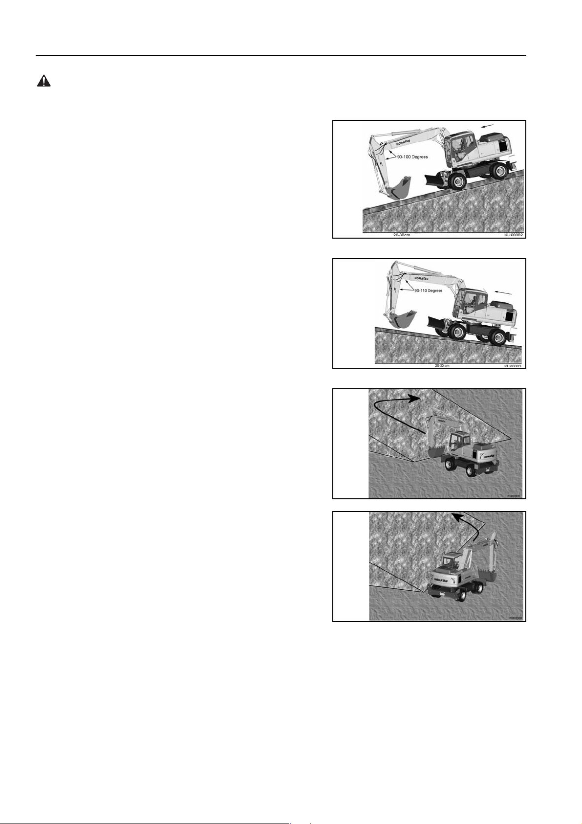
TRAVELLING ON SLOPES
● Travelling on hills, banks or s lo pes tha t ar e s teep co uld result
Downhill
in the machine tipping over or slipping.
● On hills, banks or slopes, carry the bucket closer to the
ground, approximately 20 to 30 cm above the ground. In case
of emergency, quickly lower the bucket to the ground to help
the machine stop and prevent it from tipping over.
● Do not turn on slopes or travel across slopes. Always go
down to a flat place to perform these operations.
Uphill
Method of travelling on slopes, see "RECOMMENDATIONS FOR TRAVELLING (182)"
Do not travel up and down on grass, fallen leaves, and wet steel
plates. These materia ls ma y a llo w th e m ac hin e to sl ip , if it is tr avelling sideways. Keep travel speed very low.
INCORRECT
CORRECT
30 PW160-7H VEAM390100
Page 31

SAFETY PRECAUTION DURING OPERATION
WARNING: Failure to follow these safety precautions may lead to a serious accident.
PROHIBITED OPERATIONS
● Do not dig the work face und er an o ve rh ang . This m ay cau se
INCORRECT
the overhang to collapse and fall on top of the machine.
● Do not carry out deep dig gin g un der th e fr ont of th e ma chi ne .
The ground under the machi ne may collapse and cause the
machine to fall.
DO NOT GO CLOSE TO HIGH-VOLTAGE CABLES
Going close to high-vo ltage cables can cause electric shock.
Always maintain the safe distance given below, between the
machine and the electric cable.
● The following actions are effective in preventing accidents.
1) Wear shoes with rubber or leather soles.
2) Use a signalman to give warning if the machine
approaches too close to the electric cable.
● If the work equipment should touch the electric cable, the
operator should not leave the operator’s compartment.
.
INCORRECT
● When carrying out operations near high voltage cables, do
not let anyone come close to the machine.
● Check with the elec tricity company about the voltage of the
cables before starting operations.
Voltage Min. safety distance
6.6 kV 3 m
33.0 kV 4 m
66.0 kV 5 m
154.0 kV 8 m
275.0 kV 10 m
PW160-7H VEAM390100 31
Page 32

PRECAUTION DURING OPERATION SAFETY
WARNING: For reasons of safety, always follow these safety precautions.
DO NOT HIT WORK EQUIPMENT
● When working in places where there are height limits, such as
in tunnels, under bridges, under electric cables, or in garages,
be extremely careful not to hit the boom or arm.
ENSURE GOOD VISIBILITY
● When working in dar k places, install working lamps, and set
up lighting in the work area if necessary.
● Stop operations if the visibility is po or, such as in mist, snow,
or rain, and wait for the weather to improve to a condition that
allows the operation to be carried out safely.
OPERATE CAREFULLY ON SNOW
● When working on snow or icy roads, even a sli ght slope may
cause the machine to sl ip to the side, so always trav el at low
speed and avoid sudden starting, stopping, or turning.
● When there has been heavy snow, the road shoulder and
objects placed beside the road are b uried in the snow and
cannot be seen, so always carry out snow-clearing operations
carefully.
WORKING ON LOOSE GROUND
● Avoid operating your ma chine too close to the e dge of cliffs,
overhangs, and deep ditches. If these areas collapse, your
machine could fall or tip over and result in serious injury or
death. Remember that the soil after heavy rain or blasting is
weakened in these areas.
● Earth laid on the ground and the soi l near ditches are loose.
They can collapse under the weight or vibration of your
machine.
● Install the HEAD GUARD (FOPS) if work ing in areas where
there is danger of falling rocks and dirt.
DO NOT HIT THE OPERATOR CAB (for two piece boom only)
● When the second boom cylinder is retracted, the bucket or
the attachment can hit the operator cab or chassis.
● Operate work equipment slowly and carefully to avoid any
injury and damage.
32 PW160-7H VEAM390100
Page 33

SAFETY PRECAUTION DURING OPERATION
WARNING: Failure to follow these safety precautions may lead to a serious accident.
OPERATIONS ON SLOPES
● When working on slopes, there is danger that the machine
may lose its b alance an d turn ove r when th e swing or work
equipment are oper ated. Alwa ys carry out th ese operatio ns
INCORRECT
carefully.
● Do not swing the work equipm ent from the uphill side to the
downhill side when the bucket is loade d. This operatio n is
dangerous.
(See the upper diagram on the right.)
● If the machine has to be used on a slope, pile the soil to make
a platform that will keep the machine as horizontal as possi-
CORRECT
ble.
(See the lower diagram on the right.)
Piled soil on slope, see "RECOMMENDATIONS FOR
TRAVELLING (182)"
Platform
PW160-7H VEAM390100 33
Page 34

PRECAUTION DURING OPERATION SAFETY
R
WARNING: For reasons of safety, always follow these safety precautions.
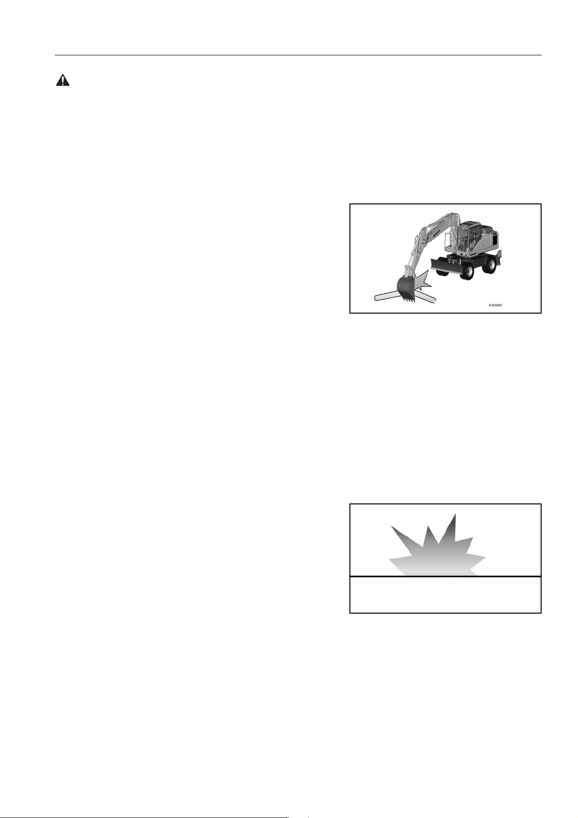
PARKING THE MACHINE
Park on level ground whenever possible. If not possible, chock
the wheels, lo wer the b ucket to the gr ound an d thrus t the bu cket
CORRECT
in the ground.
● When parking on public roads, provide fences and signs,
such as flags or lights, on the mac hine to warn passers by to
be careful. Be sure that the machine, flags o r lights do not
obstruct traffic.
EMARK
In certain conditions it may be possible for the safety lock
lever to contact the left hand arm rest on the operator seat.
To avoid this, always ensure that the left hand arm rest i s sto wed
in the fully up position before operating the safety lock lever.
● When leaving the machine, lo wer the work equipment com-
pletely to the gr ound, rai se the safe ty loc k lever t o the LOCK
position, then stop the engine and use the key to lock the
machine. Alwa ys take the key with you.
WARNING
if the control lever is touched by accident, the work equipment or the machine may move suddenly, and this may lead
to a serious accident. Before leaving the operator’s compartment, always raise the sa fety lock lever to lock t he work
equipment controls.
Places to lock, see "LOCKING (190)"
LOCK
UNLOCK
34 PW160-7H VEAM390100
Page 35

SAFETY PRECAUTION DURING OPERATION
WARNING: Failure to follow these safety precautions may lead to a serious accident.
TRANSPORTATION
LOADING AND UNLOADING
● Loading and unloading the machine always involves potential
hazards. EXTREME CAUTION SHOULD BE USED.
When loading or unloading the mac hine, run the engine a t
low idling and travel at low speed.
● Perform loading and unloading on firm, level ground only.
Maintain a safe distance from the edge of a road.
● ALWAYS block the wheels of the hauling vehicle and place
blocks under both ramps before loading and unloading.
● ALWAYS use ramps of adequate strength. Be sure the ramps
are wide and long enough to provide a safe loading slope.
● Be sure that the r am ps ar e sec ur el y pos i tio ned and fa ste ned,
and that the two sides are at the same level as one another.
Ramp
Block
Distance between ramps
Blocks
AD052900B
● Be sure the ramp surface i s clean and free of grease, oil , ice
and loose materials. Remove dirt from the machine wheels.
● NEVER correct your steering on the ramps. If necessary,
drive away from the ramps and climb again.
● Swing the upper structure with extr eme care on the trailer to
avoid a possible accident caused by body instability.
● After loading, block the machine wheels and secure the
machine with tie-downs.
● Do not slew the machine when the work equipme nt ha s been
removed or the machine has been supplied without work
equipment.
The machine may tip i f the machine slewed when no work
equipment is fitted.
Loading and unloading, see "TRANSPORTATION (195)"
SHIPPING
● When shipping the machine on a hauling vehicle, obey all
state and local laws governing the weight, width, and length
of a load. Also obey all applicable traffic regulations.
● Determine the shipping route while taking into account the
width, height and weight of the load.
PW160-7H VEAM390100 35
Page 36

PRECAUTION DURING OPERATION SAFETY
WARNING: For reasons of safety, always follow these safety precautions.
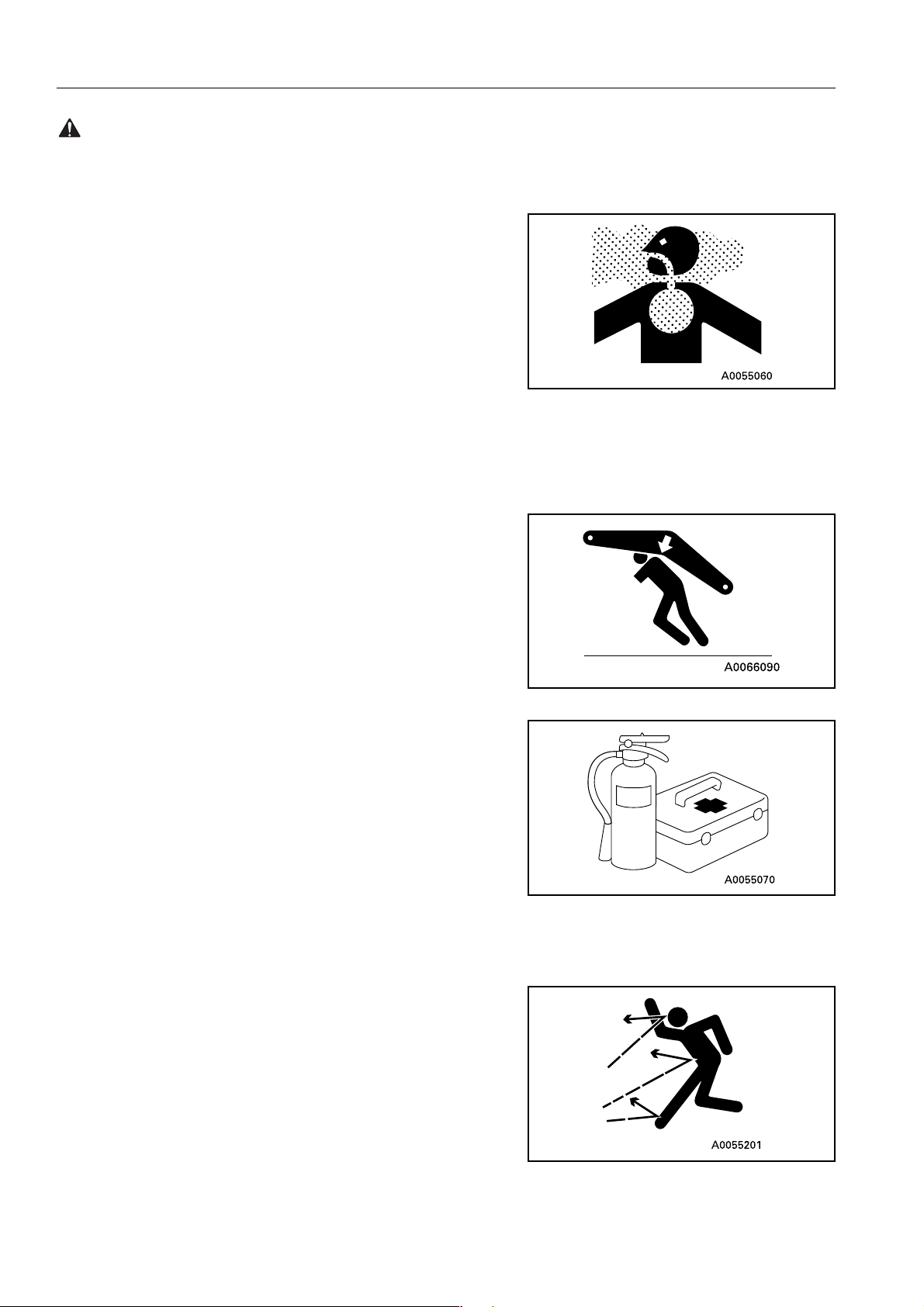
BATTERY
BATTERY HAZARD PREVENTION
● Battery electrolyte contains sulphuric acid and can quickly
burn the skin and eat hol es in clothing. I f you spill acid on
yourself, immediately flush the area with water.
● Battery acid coul d cause bl indness if splashed into the eye s.
If acid gets into the eyes, flush them immedi ately with large
quantities of water and see a doctor at once.
● If you accidentally drink acid, drink a large quantity of water or
milk, beaten egg or v eg etable o il. Cal l a do cto r or poi son pre-
vention centre immediately.
● When working with batteries. AL WAYS wear safety glasses or
goggles.
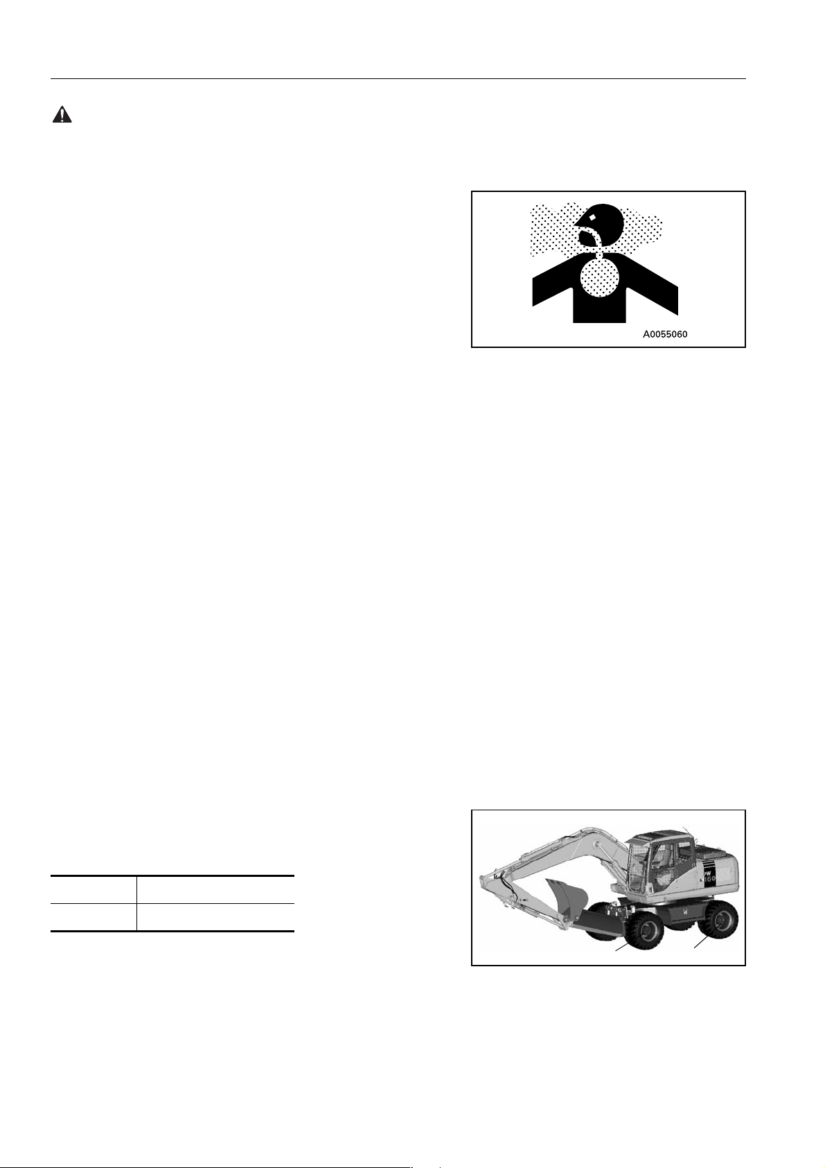
● Batteries generate hydrogen gas. Hydrogen gas is very
EXPLOSIVE, and is easily ignited with a small spark or flame.
● Before working with batteries, stop the engine and turn the
starting switch to the OFF position.
● Avoid short-circuiting th e b atte ry t er min al s throu gh ac ci den tal
contact with metallic objects, such as tools, across the termi-
nals.
● When removing or installi ng, check which is the positive (+ )
terminal and negative (-) terminal.
● Tighten the battery cap securely.
● Tighten the battery terminals securely. Loosened terminals
can generate sparks and lead to an explosion.
● When removing battery cap wear rubber groves to prevent
electrolyte contact with skin.
STARTING WITH BOOSTER CABLES
● ALWAYS wear safety glasses or goggles when starting the
machine with booster cables.
● When starting from another machine, do not allow the two
machines to touch.
● Be sure to connect the posi tive (+) cable first whe n installing
the booster cables. Disconnect the ground or negative (-)
cable first when removing them.
● If any tool touches between the po sitive (+) ter minal and the
chassis, it will c au se spar ks. T hi s is dangerous, so be su re to
work carefully.
INCORRECT
A0067320A
● Connect the batteries i n parall el : p osi ti ve to pos it iv e a nd neg -
ative to negative.
36 PW160-7H VEAM390100
Page 37

SAFETY PRECAUTION DURING OPERATION
WARNING: Failure to follow these safety precautions may lead to a serious accident.
● When connecting the ground cable to the frame of the
machine to be started, be sure to connect it as far away as
possible from the battery.
Starting with booster cables, see "DISCHARGED BATTERY (211)"
TOWING
WHEN TOWING, ATTACH WIRE TO FRAME
● Injury or death could result if a disabled machine is towed
incorrectly.
● If your machine is towed by another machine, ALWAYS use a
wire rope with a sufficient towing capacity.
● NEVER allow a disabled machine to be towed on a slope.
Towing holes
on front
● Do not use a kinked or frayed wire rope.
● If towing on the highway, a rigid tow bar should be used and
not a tow rope of any kind.
● Do not straddle the towing cable or wire rope.
● When connecting up a towing machine, do not let anyone
enter the area between the towing machine and the equipment being towed.
● Set the towing machine and the towing connection of the
equipment being towed in a straight line when connecting it.
● Place pieces of wood between the wire ropes and chassis
body to protect them from wear of damage.
When towing the machine without the engine running or in the
advent of loss of hydraulic pressure, its is necessary to manually
release the park brake, as follows.
View on transmission
Releasing the park brake before towing:
1. Unscrew bolt (A) 2-3 turns which will allow bolt (B) to rotate
(DO NOT REMOVE BOLT ’A’ ).
Undercarriage
Towing holes
on rear
Undercarriage
B
2. Turn park brake release bolt (B) 180 degrees, the indicator
mark located at the top, moves to the bottom, which will dis-
A
engage the park brake.
3. Re-tighten bolt (A) to lo ck the park brake in the disengaged
position for towing.
To reset the park brake:
A
1. Unscrew bolt (A) (Torque=20Nm)2~3 turns, this allows bolt
(B) to rotate. (DO NOT REMOVE BOLT ’A’)
2. Turn park brake release bolt (B) 180 degrees so that indicator
mark is located at the top position.
3. Re-tighten bolt (A) (Torque 20Nm)
PW160-7H VEAM390100 37
Page 38

PRECAUTION DURING OPERATION SAFETY
WARNING: For reasons of safety, always follow these safety precautions.
WARNING
Operator must not operate the travel system (i.e rotate the
travel motor) when the transmission disengagement pin is
rotated to towing position.
BUCKET WITH HOOK OR BUCKET LINK WITH LIFTING EYE
GENERAL PRECAUTIONS
LIFTING CAPACITY
● Never attempt to lift a load which would exce ed the li ft capac-
ity of the machin e sh own i n the app ro pr iat e li ft ca pacit y char t.
Exceeding the lift capacity of the machine could cause the
machine to ti p over or caus e the load to fa ll. Th e lift capac ity
charts are shown in pages 56 to 68, and are affixed inside the
operators cabin.
● Be careful to use the correct lift capacity chart for your
machine considering the boom type, the arm length, and the
undercarriage attachments installed.
● Lifting operations should always be conducted on firm flat
ground. Do not attemp t lifting operations on slopes or on
unstable ground.
● Always select L mode for lifting operations.
SPECIAL HOOK
● When carrying out lifting work, a spec ial lifting hook or lifting
eye is necessary.
● The lifting hook must be fitted with a s afety latch to prevent
accidental un-hooking of the load.
❍ Check safe working load of lifting equipment.
38 PW160-7H VEAM390100
Page 39

SAFETY PRECAUTION DURING OPERATION
WARNING: Failure to follow these safety precautions may lead to a serious accident.
● The following operations are prohibited.
❍ Lifting loads with a wire rope fitted around the bucket
teeth.
❍ Lifting loads with the wire rope wrapped directly around
the boom or arm.
CHECKING HOOK
● When lifting a load, ca rry out the followi ng checks to confi rm
that there is no abnormality before starting operations.
❍ Check that there are no cracks or deformation in the lift-
ing equipment.
❍ Check that there is no abnormality in the safety latch of
the hook.
HOOKING WIRE ROPE SECURELY TO HOOK
● When performing lifting operation, securely hook the wire
rope onto the special lifting hook or lifting eye.
PRECAUTIONS FOR MACHINE INSTALLATION
● After carrying out a preliminary inspection of ground condi-
tions, select a flat, solid location. Confirm that the machine
can be safely operated without toppling or rolling.
PROHIBITED OPERATIONS OTHER THAN MAIN APPLICATIONS
● When performing li fting opera tion, ne ve r raise or lower a per-
son.
NO PERSONS SHALL BE PERMITTED TO ENTER THE
WORKING AREA
● Due to the possi ble danger of the load fall ing or of collision
with the load, no persons shall be allowed in the working
area.
OPERATION SUPERVISOR
● Before performing lifting operation, designate an operation
supervisor.
Always execute operation according to his instructions.
❍ Execute operating methods and procedures under his
direction.
❍ Select a person responsible for signal ling. Operate only
on signals given by such person.
HANDLING OF WIRE ROPES ETC.
● Wear leather gloves when handling wire ropes.
PW160-7H VEAM390100 39
Page 40

PRECAUTION DURING OPERATION SAFETY
WARNING: For reasons of safety, always follow these safety precautions.
PROTECTING EYES
● Some oils and fluids can damage eyes. Refer to manufac-
tured data sheet for handling and storage instructions.
PRECAUTIONS FOR LIFTING OPERATION
GRADUAL LIFTING OPERATION
● When carrying out lifting operations, run the engine at low
idling and use the L (lifting operation mode).
● Avoid sudden lever shifting and acceleration.
● Swing speed is three to four times that of mobile cranes.
Therefore, be especially careful when performing swing operation.
NEVER LEAVE THE OPERATOR’S SEAT
● Never leave the operator’s seat while lifting a load.
NEVER CARRY OUT EXCESSIVE OPERATIONS
● Operation exceeding machine performance may result in
accident or failure.
● Carry out lifting operation within specified load limit of
machine and lifting equipment.
● Never carry out operations which may damage the machine
such as overload or over-impact-load.
● Never drag a load laterally or longitudinally, nor retract the
arm, otherwise, a dangerous situation may result.
NEVER TRA VEL WHILE LIFTING A LOAD
● Never travel while carrying a load.
OPERATING POSTURE
● If the machine posture is no t correct, the wire ropes or ring
may detach from the hook. Confirm that the hook angle is correct to avoid this.
HANDLING OF FLUIDS
INCORRECT
INCORRECT
● Some oils and other fluids, su ch as Antifree ze, can be harm-
ful to you and the environment, you should therefore always
follow the man ufact urers inst ruct ions reg arding sto rage , han dling and disposal.
HANDLING OF USED ENGINE OILS
● Avoid contact with used engine oils.
● Refer to engine oils da ta sheet for handli ng and sto rage pre-
cautions.
40 PW160-7H VEAM390100
Page 41

SAFETY PRECAUTION DURING OPERATION
WARNING: Failure to follow these safety precautions may lead to a serious accident.
HANDLING OF OILS
● For diesel oils, hydraulic oils and oils used in the swing
machinery, PTO, transmission axles and hubs avoid prolonged or frequent contact with skin.
● Refer to manufactur ers data sheet for handling a nd storage
precautions.
HANDLING OF FLUIDS
● For antifreeze a nd grease refer to manufacturers data sheet
for handling and storage precauti ons.
PW160-7H VEAM390100 41
Page 42

PRECAUTIONS FOR MAINTENANCE SAFETY
WARNING: For reasons of safety, always follow these safety precautions.
PRECAUTIONS FOR MAINTENANCE
BEFORE CARRYING OUT MAINTENANCE
WARNING TAG
● If others start the engine or operate the controls while you are
performing service or lubricati on, you coul d suffer ser ious
injury or death.
● ALWAYS attach the WARNING TAG to the control lever in the
operator’s cab to alert others that you are working on the
machine. Attach addi tion al warni ng tags arou nd the machine,
if necessary.
● These tags are available from your Komatsu distrib utor. (Part
no. 20E-00-K1340)
PROPER TOOLS
● Use only tools suited to the task. Using damaged, low quality,
faulty, or makeshift tools could cause personal injury.
Tools, see "INTRODUCTION OF NECESSARY TOOLS
(236)"
PERIODIC REPLACEMENT OF SAFETY CRITICAL PARTS
● Replace the following fire-related components periodically:
Fuel system: Fuel hose, spilling hose, and fuel tube cap.
Hydraulic system: Pump outlet hose.
● Replace these components periodically with new ones,
regardless of whether or not they appear to be defective.
These components deteriorate over time.
● Replace or repair any such components if any defect is found,
event though they have not reached the time specified.
Replacement of safety critical components, see "PERIODIC REPLACEMENT OF SAFETY CRITICAL PARTS
(238)"
STOP THE ENGINE BEFORE CARRYING OUT INSPECTION
AND MAINTENANCE
● Always stop the machine on firm flat ground and stop the
engine before carrying out inspection and maintenance.
● If it is necessary to run th e engin e when carry ing out mai nte-
nance, such as when cleaning the inside of the radiator,
Heat
Heat
Off
Off
On
On
Raise the safety lock lever to the LOCK position and carry out
the operation with two workers.
Start
Start
42 PW160-7H VEAM390100
Page 43

SAFETY PRECAUTIONS FOR MAINTENANCE
WARNING: Failure to follow these safety precautions may lead to a serious accident.
● One worker should sit in the op erator’s seat so that he can
stop the engine immediately if necessary. He should also be
extremely careful not to touch any lever by mistake. Touch the
levers only when they have to be operated.
● The worker carrying out the maintenance should be
extremely carefu l not to to uch or get caught in the moving
parts.
RULES TO FOLLOW WHEN ADDING FUEL OR OIL
● Spilt fuel and oil may cause you t o slip, so always wipe it up
immediately.
● Always tighten the cap of the fuel and oil fillers securely.
● Never use fu el for washing any parts.
LOCK
UNLOCK
● Always add fuel and oil in a well-ventilated place.
PW160-7H VEAM390100 43
Page 44

PRECAUTIONS FOR MAINTENANCE SAFETY
WARNING: For reasons of safety, always follow these safety precautions.
RADIATOR WATER LEVEL
● If it is necessary to add wa ter to the radia tor, stop the engine
and allow the engine and radiator to coo l do wn befo re addi ng
the water.
● Slowly loosen the c aps to relieve pressure before remo ving
the caps.
USE OF LIGHTING
● When checking fuel, oil, coolant, or battery electrolyte, always
use lighting with anti-explosion specifications.
If such lighting equipment is not used, there is danger of
explosion.
44 PW160-7H VEAM390100
Page 45

SAFETY PRECAUTIONS FOR MAINTENANCE
WARNING: Failure to follow these safety precautions may lead to a serious accident.
DURING MAINTENANCE
PERSONNEL
● Only authorised personnel can service and repair the
machine. Extra precaution should be used when grinding,
welding, and using a sledge-hammer.
ATTACHMENTS
● Place attachments that have been removed from the machine
in a safe place so that they do not fall. If they fall on you or
others, serious injury could result.
WORK UNDER THE MACHINE
● Always lower all mova ble wor k equip ment to the gr ound or to
their lowest position befo re performing service or repairs
under the machine.
● Always chock the wheels of the machine securely.
● Never work under the machi ne if the machine is poorly su p-
ported.
KEEP THE MACHINE CLEAN
● Spilt oil or grease, or scattered tools or broken pieces are
dangerous because they may cause you to slip or trip.
Always keep your machine clean and tidy.
● If water gets into the electric al system, there is danger that
the machine may not move or may move unexpectedly.
Do not use water or steam to clean the sensors, connectors,
or the inside of the operator’s compartment.
PRECAUTIONS WITH BATTERY
● When repairing the electrical system or when carrying out
electrical welding, remove the negative (-) terminal of the battery to stop the flow of current.
PW160-7H VEAM390100 45
Page 46

PRECAUTIONS FOR MAINTENANCE SAFETY
WARNING: For reasons of safety, always follow these safety precautions.
HANDLING HIGH-PRESSURE HOSES
● Do not bend high-pressure hoses or hit them with hard
objects. Do not use any bent or cracked piping, tubes or
hoses. They may burst during use.
● Always repair any loose or broken fuel hoses or oi l hoses. If
fuel or oil leaks, it may cause a fire.
PRECAUTIONS WITH HIGH PRESSURE OIL
● Do not forget that the work equipment circuits are always
under pressure.
● Do not add oil, drain oil, or c arry out maintenance or inspec-
tion before completely releasing the internal pressure.
● If oil is leaking under high pressure from small holes, it is dan-
gerous if the jet o f high-pre ssure oil hits your skin or en ters
your eyes. Always wear safety glasses and thick gloves, and
use a piece of cardboard or a sheet of wood to check for oil
leakage.
A0055180A
● If you are hit by a jet of high-pressure oil, consult a doctor
immediately for medical attention.
PRECAUTIONS WHEN CARRYING OUT MAINTENANCE AT
HIGH TEMPERATURE OR HIGH PRESSURE
● Immediately after stopping operations, the engine cooling
water and oil at all parts is at high temperature and under high
pressure.
In this condition, if the cap is removed, or the oi l or water are
drained, or the filte rs a re r ep laced , th is m ay r esul t i n burns o r
other injury. Wait for the temperature to go down, then carry
out the inspection and maintenance in accordance with the
procedures given in this manual.
Cleaning inside or cooling sys tem, see "WHEN
REQUIRED (247)"
A055190A
Checking cooling water level , hydraulic oil level, see
"CHECK COOLANT LEVEL, ADD WATER (267)"
Checking lubricating oil level, adding oil, see "MAINTENANCE SCHEDULE CHART (240)"
Changing oil, replacing filters, see "MAINTENANCE
SCHEDULE CHART (240)"
46 PW160-7H VEAM390100
Page 47

SAFETY PRECAUTIONS FOR MAINTENANCE
WARNING: Failure to follow these safety precautions may lead to a serious accident.
ROTATING FAN AND BELT
● Keep away from rotating parts and be car eful not to let any-
thing get caught in them.
● If your body or tools touch the fan blades or fan belt, they may
be cut off or sent flying, so never touch any rotating parts.
WASTE MATERIALS
● Never dump waste oil in a sewer system, rivers, etc.
● Always put oil drained from your machine in containers.
Never drain oil directly on the ground.
● Obey appropriate laws and regulations when disposing of
harmful materials such as oil, fuel, coo lant, solvent, filters,
batteries, and others.
A0055220A
PW160-7H VEAM390100 47
Page 48

POSITION FOR ATTACHING SAFETY LABELS SAFETY
WARNING: For reasons of safety, always follow these safety precautions.
POSITION FOR ATTACHING SAFETY LABELS
Always keep these labels clean. If they are los t or damaged,
attach them again or replace them with a new label
There are other labels i n addi ti on to th e sa fety labels listed as follows, so handle them in the same way.
Safety labels are available from your Komatsu distributor.
POSITION FOR ATTACHING SAFETY LABELS
13
10
17
8
2
18
11
1
19
9
2
8
15
15
2
7
2
3
14
4
5
6
2
12
15
15
2
5
48 PW160-7H VEAM390100
Page 49

SAFETY POSITION FOR ATTACHING SAFETY LABELS
WARNING: Failure to follow these safety precautions may lead to a serious accident.
1. Warnings for read the manuals, safety lock, emergency steering, power lines, do not r ide on machine , falling obj ects and
bucket hitting cab. This i s loca ted on th e right ha nd windo w
inside the cab (20E-00-K1890)
● Improper operation and maintenance can cause serious
injury or death.
● Read the manuals before operation.
● Follow instruct ions and warnings in the manuals and l abels
on the machine.
● Keep this manual in the machine cab, near operator.
● If this manual is lost, please c ontact Komatsu distributor for
replacement.
● Always raise safety lock lever when leaving operators seat.
● Normal steering can only be operated when the engine is run-
ning.
● Emergency steering is only to be used when stopping the
machine safely.
● Serious injury or death can occur if the machine or attach-
ments are not kept a safe distance away from electric lines.
● No passengers allowed to ride on machine while it is moving.
● Do not operate where a danger of fal ling obje cts exists. Con-
sult your dealer for fitting of FOPS protection.
● Bucket hits operator cab. Read manual before operation.
PW160-7H VEAM390100 49
Page 50

POSITION FOR ATTACHING SAFETY LABELS SAFETY
2. There are 6 amber reflectors loc ated on the revolving frame
and arm of the machine (20G-46-K1681)
3. Warning for unsafe machine. Located on the left or right hand
levers (20E-00-K1340)
● Do not start the engine.
4. Warning for accumulator is located below operator cab
(20E-00-K1210)
Warnings for handling accumulator.
Explosion hazard
● Keep away from flame.
● Do not weld or drill.
● Read operation manual before operation.
5. Warning for staying clear (20K-00-31280)
Keeping out of moving area.
To prevent SEVERE INJURY or DEATH.
Do the following before moving the machine or its attachments:
● Sound horn to alert people nearby.
● Be sure no one is on or near machine or in the swing area.
● Rotate cab for full view of travel path if it can be done safely.
● Use spotter if view is obstructed. Follow above even if
machine equipped with travel alarm and mirrors.
50
Page 51

SAFETY POSITION FOR ATTACHING SAFETY LABELS
R
6. Warning for hot objects (20E-00-K1190)
Warning for high temperature coolant and oil, hot water and oil
hazard.
To prevent hot water and oil from spurting out:
● Turn engine off.
● Allow water to cool.
● Slowly loosen cap to relieve pressure before removing.
● Read operation manual before operation.
7. Safety lock. This is located on the right hand window of the
machine (20K-00-31181)
● Read operation manual before operation.
● With safety lock lever raised the control levers and pedals are
disabled.
● With safety lock lever lowered and control lever lock switch on
the machine can travel.
● With safety lock le ver l owered and co ntrol lever lo ck swi tch of f
work equipment and travel can be operated.
EMARK
In certain conditions it may be possible for the safety lock
lever to contact the left hand arm rest on the operator seat.
to avoid this , alway s ensure that the left ha nd arm r est is st owed
in the fully up position before operating the safety lock lever.
51
Page 52

POSITION FOR ATTACHING SAFETY LABELS SAFETY
8. Warning for staying clear. This is fitted on both sides of arm
(20E-00-K1140)
Keeping out of moving area.
To prevent SEVERE INJURY or DEATH.
Do the following before moving the machine or its attachments:
● Sound horn to alert people nearby.
● Be sure no one is on or near machine or in the swing area.
● Rotate cab for full view of travel path if it can be done safely.
● Use spotter if view is obstructed. Follow above even if
machine equipped with travel alarm and mirrors.
9. Falling from upper structure warni ng. This is located on the
front of the fuel tank, on inside of walkway door, top of the
counterweight.(20E-00-K1110)
(
● WARNING
falling from upper structure.
● Keep away from sides of machine.
● Keep off counterweight.
● Do not ride on machine when it is moving.
52
Page 53

SAFETY POSITION FOR ATTACHING SAFETY LABELS
10. Stop engine warning (20E-00-K1310)
● Do not open cover while engine is running.
11. Front window lock warnin g. This is located on the rear window (09803-A0481)
● Always lock window in raised or lowered position.
12. High pressure oil warning (20E-00-K1270)
53
Page 54

POSITION FOR ATTACHING SAFETY LABELS SAFETY
13. (20G-00-31030)
Radiator fill volume warning. This is located on top of the radiator
unit.
14. (20K-00-31360)
Read operation manual before operation.This is located inside
the cab.
15. Red reflector (20G-47-K1690)
16. (20Y-00-K2220)
● Emergency exit
● Read operation manual before operation
17. Travel Height -UK spec only. This is fitted to the top right hand
corner of the front window (20E-00-K1720)
54
Page 55

SAFETY POSITION FOR ATTACHING SAFETY LABELS
18. Operation of attachments is located on the right hand window
(20K-00-31140)
19. Lift warning plate. This is located on the righ t hand window
(20E-00-K1450)
20. Do not lift more than the specified load of the machine.
21. Warning for machine tipping over. (20K-00-31770)
● Do not slew the machine when the work equipme nt ha s been
removed or the machine has been supplied without work
equipment.
● The machine may tip if the machine slewed when no work
equipment is fitted.
WARNING
Failure to follow thes e saf ety pre cautions may lead to a serious accident.
55
Page 56

LIFTING CAPACITY CHART PW160-7H SAFETY
LIFTING CAPACITY CHART PW1 60-7H
ONE PIECE BOOM Lift capacity tables
When removing bucket, linkage or cylinder, lifting capacities can
be increased by their respective weights.
A - Reach from swing center
B - Bucket hook height
C - Lifting capacities, including bucket (495 kg),
linkage (120 kg) and bucket cylinder (109 kg)
OF: Lifting capacity (Rating over front)
OS: Lifting capacity (Rating over side)
- MAX: Rating at maximum reach
56
Page 57

SAFETY LIFTING CAPACITY CHART PW160-7H
Reach (A)
MAX 7.5m 6.0m 4.5m 3.0m
Model
Arm length
Height (B)
7.5m *2450 *2450
6.0m *2100 *1800 3150 2200
4.5m *1950 1450 3100 2150 5050 3500
3.0m 1900 1250 2050 1350 2950 2050 4700 3200
2.1m
1.5m 1850 1200 2000 1300 2850 1900 4350 2900
0.0m 1900 1250 1950 1250 2750 1800 4200 2750
-1.5m 2100 1400 2700 1750 4150 2700 *6900 5000
-3.0m 2700 1800 2750 1850 4200 2750 *6550 5150
7.5m *1800 *1800
6.0m *1600 *1600 3150 2200
4.5m *1550 1350 *2000 1400 3100 2150
3.0m *1600 1150 2050 1350 3000 2050 4750 3250 9500 6050
2.5m
1.5m *1700 1100 1950 1300 2850 1900 4450 2950
OF OS OF OS OF OS OF OS OF OS
No Attachments
0.0m 1750 1150 1900 1250 2750 1800 4250 2750 *4400 *4400
-1.5m 1950 1250 2700 1750 4150 2700 *7100 5050
-3.0m 2400 1600 2700 1800 4200 2750 *7550 5150
7.5m *1450 *1450 *2350 2150
6.0m *1300 *1300 *1450 1350 *2900 2200
4.5m *1200 1100 2050 1350 3100 2150
3.0m *1200 950 2000 1300 2950 2000 4800 3300
3.0m
1.5m *1300 900 1900 1250 2800 1850 4400 2900
0.0m *1450 900 1850 1200 2650 1750 4150 2700 *4050 *4050
-1.5m 1650 1000 1800 1150 2600 1650 4050 2600 *5950 4800
-3.0m 1950 1250 2600 1650 4050 2600 8100 4900
57
Page 58

LIFTING CAPACITY CHART PW160-7H SAFETY
Reach (A)
MAX 7.5m 6.0m 4.5m 3.0m
Model
Arm length
Height (B)
7.5m *2450 *2450
6.0m *2100 *2100 *3750 2600
4.5m *1950 1750 *4700 2550 *5250 4150
3.0m *1950 1550 *3350 1650 *5100 2450 *6700 3800
2.1m
2.5m
1.5m *2050 1500 4000 1600 *5400 2300 *7500 3500
0.0m *2300 1500 *3450 1550 *5400 2200 *7450 3350
-1.5m *2750 1700 *4850 2200 *6650 3300 *6900 6250
-3.0m *2900 2200 *3200 2250 *5050 3350 *6550 6400
7.5m *1800 *1800
6.0m *1600 *1600 *3200 2600
4.5m *1550 *1550 *2000 1700 *4100 2550
3.0m *1600 1450 *3300 1650 *4900 2450 *6400 3900 *10050 7350
1.5m *1700 1400 4000 1600 *5300 2300 *7350 3600
OF OS OF OS OF OS OF OS OF OS
Front/Rear Dozer Blade Only
0.0m *1950 1400 3950 1550 *5400 2200 *7550 3400 *4400 *4400
-1.5m *2400 1600 *5050 2150 *6950 3300 *7100 6250
-3.0m *3150 1950 *3850 2200 *5550 3350 *7550 6400
7.5m *1450 *1450 *2350 *2350
6.0m *1300 *1300 *1450 *1450 *2900 2650
4.5m *1200 *1200 *2700 1650 *3250 2550
3.0m *1200 1200 *3350 1600 *4350 2450 *5450 3900
3.0m
1.5m *1300 1150 3950 1550 *5050 2250 *6900 3500
0.0m *1450 1200 3850 1500 *5300 2150 *7400 3300 *4050 *4050
-1.5m *1700 1300 *3700 1450 *5100 2050 *7100 3200 *5950 *5950
-3.0m *2200 1600 *4250 2050 *6000 3200 *8550 6150
58
Page 59

SAFETY LIFTING CAPACITY CHART PW160-7H
Reach (A)
MAX 7.5m 6.0m 4.5m 3.0m
Model
Arm length
Height (B)
7.5m *2450 *2450
6.0m *2100 *2100 *3750 2950
4.5m *1950 *1950 *4700 2900 *5250 4700
3.0m *1950 1800 *3350 1900 *5100 2800 *6700 4350
2.1m
1.5m *2050 1700 *4150 1850 *5400 2650 *7500 4050
0.0m *2300 1800 *3450 1850 *5400 2550 *7450 3900
-1.5m *2750 2000 *4850 2500 *6650 3850 *6900 *6900
-3.0m *2900 2500 *3200 2600 *5050 3900 *6550 *6550
7.5m *1800 *1800
6.0m *1600 *1600 *3200 2950
4.5m *1550 *1550 *2000 1950 *4100 2900
3.0m *1600 *1600 *3300 1900 *4900 2800 *6400 4450 *10050 *8550
2.5m
1.5m *1700 1600 *4150 1850 *5300 2650 *7350 4100
OF OS OF OS OF OS OF OS OF OS
0.0m *1950 1650 *4050 1800 *5400 2550 *7350 3900 *4400 *4400
Rear Outrigger Only
-1.5m *2400 1850 *5050 2500 *6950 3850 *7100 *7100
-3.0m *3150 2250 *3850 2550 *5550 3900 *7550 7500
7.5m *1450 *1450 *2350 *2350
6.0m *1300 *1300 *1450 *1450 *2900 2800
4.5m *1200 *1200 *2700 1800 *3250 2750
3.0m *1200 *1200 *3350 1750 *4350 2600 *5450 4200
3.0m
1.5m *1300 1250 4050 1650 *5050 2450 *6900 3800
0.0m *1450 1250 3950 1600 *5300 2300 *7400 3550 *4050 *4050
-1.5m *1700 1400 *3700 1550 *5100 2200 *7100 3450 *5950 *5950
-3.0m *2200 1700 *4250 2200 *6000 3450 *8550 6800
59
Page 60

LIFTING CAPACITY CHART PW160-7H SAFETY
Reach (A)
MAX 7.5m 6.0m 4.5m 3.0m
Model
Arm length
Height (B)
7.5m *2450 *2450
6.0m *2100 *2100 *3750 *3750
4.5m *1950 *1950 *4700 3800 *5250 *5250
3.0m *1950 *1950 *3350 2550 *5100 3700 *6700 5800
2.1m
1.5m *2050 *2050 *4150 2500 *5400 3550 *7500 5500
0.0m *2300 *2300 *3450 2450 *5400 3450 *7450 5300
-1.5m *2750 2700 *4850 3400 *6650 5250 *6900 *6900
-3.0m *2900 *2900 *3200 *3200 *5050 *5050 *6550 *6550
7.5m *1800 *1800
6.0m *1600 *1600 *3200 *3200
4.5m *1550 *1550 *2000 *2000 *4100 3850
3.0m *1600 *1600 *3300 2550 *4900 3700 *6400 5900 *10050 *10050
2.5m
1.5m *1700 *1700 *4150 2500 *5300 3550 *7350 5550
OF OS OF OS OF OS OF OS OF OS
Dozer & Outrigger
0.0m *1950 *1950 *4050 2450 *5400 3450 *7550 5350 *4400 *4400
-1.5m *2400 *2400 *5050 3400 *6950 5250 *7100 *7100
-3.0m *3150 3050 *3850 3400 *5550 5300 *7550 *7550
7.5m *1450 *1450 *2350 *2350
6.0m *1300 *1300 *1450 *1450 *2900 *2900
4.5m *1200 *1200 *2700 2600 *3250 *3250
3.0m *1200 *1200 *3350 2500 *4350 3700 *5450 *5450
3.0m
1.5m *1300 *1300 *4050 2450 *5050 3500 *6900 5500
0.0m *1450 *1450 *4050 2350 *5300 3350 *7400 5250 *4050 *4050
-1.5m *1700 *1700 *3700 2350 *5100 3300 *7100 5150 *5950 *5950
-3.0m *2200 *2200 *4250 3300 *6000 5150 *8550 *8550
60
Page 61

SAFETY LIFTING CAPACITY CHART PW160-7H
Reach (A)
MAX 7.5m 6.0m 4.5m 3.0m
Model
Arm length
Height (B)
7.5m *2450 *2450
6.0m *2100 *2100 *3750 *3750
4.5m *1950 *1950 *4700 4550 *5250 *5250
3.0m *1950 *1950 *3350 3050 *5100 4400 *6700 *6700
2.1m
1.5m *2050 *2050 *4150 3000 *5400 4250 *7500 6700
0.0m *2300 *2300 *3450 2950 *5400 4150 *7450 6500
-1.5m *2750 *2750 *4850 4100 *6650 6450 *6900 *6900
-3.0m *2900 *2900 *3200 *3200 *5050 *5050 *6550 *6550
7.5m *1800 *1800
6.0m *1600 *1600 *3200 *3200
4.5m *1550 *1550 *2000 *2000 *4100 *4100
3.0m *1600 *1600 *3300 3050 *4900 4400 *6400 *6400 *10050 *10050
2.5m
1.5m *1700 *1700 *4150 3000 *5300 4250 *7350 6750
4 X Outrigger
0.0m *1950 *1950 *4050 2950 *5400 4150 *7550 6550 *4400 *4400
OF OS OF OS OF OS OF OS OF OS
-1.5m *2400 *2400 *5050 4100 *6950 6450 *7100 *7100
-3.0m *3150 *3150 *3850 *3850 *5550 *5550 *7550 *7550
7.5m *1450 *1450 *2350 *2350
6.0m *1300 *1300 *1450 *1450 *2900 *2900
4.5m *1200 *1200 *2700 *2700 *3250 *3250
3.0m *1200 *1200 *3350 3050 *4350 *4350 *5450 *5450
3.0m
1.5m *1300 *1300 *4050 2950 *5050 4250 *6900 6700
0.0m *1450 *1450 *4050 2850 *5300 4100 *7400 6450 *4050 *4050
-1.5m *1700 *1700 *3700 2850 *5100 4000 *7100 6350 *5950 *5950
-3.0m *2200 *2200 *4250 4000 *6000 *6000 *8550 *8550
Note for lift capacity tables:
1. Ratings are based on ISO 10567
2. Lifting capaciti es are given f or:
a) 75% of tipping load
b) rated hydraulic lift capacity 87% of max.
3. Capacities mark ed with a n aste risk ( *) are li mited b y hyd raulic
capacities
61
Page 62

LIFTING CAPACITY CHART PW160-7H SAFETY
TWO PIECE BOOM Lift capacity tables
When removing bucket, linkage or cylinder, lifting capacities can
be increased by their respective weights.
A - Reach from swing center
B - Bucket hook height
C - Lifting capacities, including bucket (495 kg),
linkage (120 kg) and bucket cylinder (109 kg)
OF: Lifting capacity (rating over front)
OS: Lifting capacity (Rating over side)
-MAX: Rating at maximum reach
62
Page 63

SAFETY LIFTING CAPACITY CHART PW160-7H
Reach (A)
MAX 7.5m 6.0m 4.5m 3.0m
Model
Arm length
Height (B)
7.5m *2300 *2300 *3650 *3650
6.0m *1900 *1900 *3250 2200 *4200 3700
4.5m *1800 1500 *4550 2150 *5100 3600 *5000 *5000
3.0m *1800 1300 *2400 1350 *5300 2050 *6900 3300
2.1m
1.5m *1900 1250 *3250 1300 *5700 1950 *7900 3050
0.0m *2100 1300 *5800 1850 *8050 2900
-1.5m *2600 1450 *5300 1850 *7400 2850 *7400 5450
-3.0m *5700 2900
7.5m *1750 *1750 *3350 *3350
6.0m *1500 *1500 *3150 2200 *3450 *3450
4.5m *1400 1300 *1750 1350 *3850 2150 *4000 3600 *3500 *3500
3.0m *1400 1150 *3150 1300 *5000 2050 *6450 3350
2.5m
1.5m *1500 1100 *3900 1250 *5500 1900 *7550 3000
OF OS OF OS OF OS OF OS OF OS
No Attachments
0.0m *1650 1100 *3850 1200 *5700 1800 *8000 2850 *4050 *4050
-1.5m *2000 1250 *5400 1750 *7550 2750 *6900 5300
-3.0m *4150 1800 *6150 2800
7.5m *1400 *1400 *2050 *2050 *2850 *2850
6.0m *1200 *1200 *2800 2250 *2700 *2700
4.5m *1100 *1100 *2500 1400 *3150 2200 *2950 *2950
3.0m *1100 1000 *3150 1350 *4150 2100 *5050 3400
3.0m
1.5m *1150 950 *3900 1250 *5300 1950 *7200 3100
0.0m *1300 950 *4350 1200 *5650 1800 *7900 2850 *4250 *4250
-1.5m *1550 1100 *3700 1200 *5550 1750 *7750 2750 *6250 5250
-3.0m *2050 1350 *4700 1750 *6750 2750 *9800 5300
63
Page 64

LIFTING CAPACITY CHART PW160-7H SAFETY
Reach (A)
MAX 7.5m 6.0m 4.5m 3.0m
Model
Arm length
Height (B)
7.5m *2300 *2300 *3650 *3650
6.0m *1900 *1900 *3250 2300 *4200 3900
4.5m *1800 1600 *4550 2300 *5100 3750 *5000 *5000
3.0m *1800 1400 *2400 1450 *5300 2200 *6900 3500
2.1m
1.5m *1900 1350 *3250 1400 *5700 2050 *7900 3200
0.0m *2100 1400 *5800 2000 *8050 3050
-1.5m *2600 1550 *5300 1950 *7400 3050 *7400 5750
-3.0m *5700 3100
7.5m *1750 *1750 *3350 *3350
6.0m *1500 *1500 *3150 2300 *3450 *3450
4.5m *1400 1400 *1750 1450 *3850 2250 *4000 3750 *3500 *3500
3.0m *1400 1200 *3150 1400 *5000 2150 *6450 3500
2.5m
1.5m *1500 1150 *3900 1350 *5500 2000 *7550 3200
OF OS OF OS OF OS OF OS OF OS
Front/Rear Dozer Blade Only
0.0m *1650 1200 *3850 1300 *5700 1900 *8000 3000 *4050 *4050
-1.5m *2000 1350 *5400 1850 *7550 2900 *6900 5500
-3.0m *4150 1900 *6150 2950
7.5m *1400 *1400 *2050 *2050 *2850 *2850
6.0m *1200 *1200 *2800 2400 *2700 *2700
4.5m *1100 *1100 *2500 1450 *3150 2300 *2950 *2950
3.0m *1100 1050 *3150 1450 *4150 2200 *5050 3600
3.0m
1.5m *1150 1000 *3900 1350 *5300 2050 *7200 3250
0.0m *1300 1050 *4350 1300 *5650 1900 *7900 3000 *4250 *4250
-1.5m *1550 1150 *3700 1250 *5550 1850 *7750 2900 *6250 5500
-3.0m *2050 1450 *4700 1850 *6750 2900 *9800 5600
64
Page 65

SAFETY LIFTING CAPACITY CHART PW160-7H
Reach (A)
MAX 7.5m 6.0m 4.5m 3.0m
Model
Arm length
Height (B)
7.5m *2300 *2300 *3650 *3650
6.0m *1900 *1900 *3250 2350 *4200 3950
4.5m *1800 1600 *4550 2300 *5100 3800 *5000 *5000
3.0m *1800 1400 *2400 1450 *5300 2200 *6900 3550
2.1m
1.5m *1900 1350 *3250 1400 *5700 2100 *7900 3250
0.0m *2100 1400 *5800 2000 *8050 3100
-1.5m *2600 1600 *5300 2000 *7400 3100 *7400 5850
-3.0m *5700 3150
7.5m *1750 *1750 *3350 *3350
6.0m *1500 *1500 *3150 2350 *3450 *3450
4.5m *1400 *1400 *1750 1450 *3850 2300 *4000 3800 *3500 *3500
3.0m *1400 1250 *3150 1450 *5000 2200 *6450 3550
2.5m
1.5m *1500 1200 *3900 1400 *5500 2050 *7550 3250
OF OS OF OS OF OS OF OS OF OS
0.0m *1650 1200 *3850 1350 *5700 1950 *8000 3050 *4050 *4050
Rear Outrigger Only
-1.5m *2000 1400 *5400 1900 *7550 2950 *6900 5650
-3.0m *4150 1950 *6150 3000
7.5m *1400 *1400 *2050 *2050 *2850 *2850
6.0m *1200 *1200 *2800 2400 *2700 *2700
4.5m *1100 *1100 *2500 1500 *3150 2350 *2950 *2950
3.0m *1100 1100 *3150 1450 *4150 2250 *5050 3650
3.0m
1.5m *1150 1050 *3900 1400 *5300 2100 *7200 3300
0.0m *1300 1050 *4350 1350 *5650 1950 *7900 3050 *4250 *4250
-1.5m *1550 1200 *3700 1300 *5550 1900 *7750 2950 *6250 5600
-3.0m *2050 1500 *4700 1900 *6750 2950 *9800 5700
65
Page 66

LIFTING CAPACITY CHART PW160-7H SAFETY
Reach (A)
MAX 7.5m 6.0m 4.5m 3.0m
Model
Arm length
Height (B)
7.5m *2300 *2300 *3650 *3650
6.0m *1900 *1900 *3250 2450 *4200 4100
4.5m *1800 1700 *4550 2450 *5100 3950 *5000 *5000
3.0m *1800 1500 *2400 1550 *5300 2350 *6900 3700
2.1m
1.5m *1900 1450 3250 1500 *5700 2200 *7900 3450
0.0m *2100 1500 *5800 2150 *8050 3300
-1.5m *2600 1700 *5300 2100 *7400 3250 *7400 6100
-3.0m *5700 3300
7.5m *1750 *1750 *3350 *3350
6.0m *1500 *1500 *3150 2450 *3450 *3450
4.5m *1400 *1400 *1750 1550 *3850 2400 *4000 4000 *3500 *3500
3.0m *1400 1350 *3150 1500 *5000 2300 *6450 3700
2.5m
1.5m *1500 1250 *3900 1450 *5500 2150 *7550 3400
OF OS OF OS OF OS OF OS OF OS
Dozer & Outrigger
0.0m *1650 1300 *3850 1400 *5700 2050 *8000 3200 *4050 *4050
-1.5m *2000 1450 *5400 2000 *7550 3150 *6900 5950
-3.0m *4150 2050 *6150 3200
7.5m *1400 *1400 *2050 *2050 *2850 *2850
6.0m *1200 *1200 *2800 2550 *2700 *2700
4.5m *1100 *1100 *2500 1600 *3150 2450 *2950 *2950
3.0m *1100 *1100 *3150 1550 *4150 2350 *5050 3800
3.0m
1.5m *1150 1100 *3900 1450 *5300 2200 *7200 3450
0.0m *1300 1150 *4350 1400 *5650 2050 *7900 3250 *4250 *4250
-1.5m *1550 1300 *3700 1400 *5550 2000 *7750 3100 *6250 5900
-3.0m *2050 1550 *4700 2000 *6750 3100 *9800 6000
66
Page 67

SAFETY LIFTING CAPACITY CHART PW160-7H
Reach (A)
MAX 7.5m 6.0m 4.5m 3.0m
Model
4 X Outrigger
Arm length
Height (B)
7.5m *2300 *2300 *3650 *3650
6.0m *1900 *1900 *3250 2500 *4200 4150
4.5m *1800 1750 *4550 2450 *5100 4000 *5000 *5000
3.0m *1800 1550 *2400 1550 *5300 2350 *6900 3750
2.1m
1.5m *1900 1450 *3250 1550 *5700 2250 7900 3500
0.0m *2100 1500 *5800 2150 *8050 3350
-1.5m *2600 1700 *5300 2150 *7400 3300 *7400 6200
-3.0m *5700 3350
7.5m *1750 *1750 *3350 *3350
6.0m *1500 *1500 * 3150 2500 *3450 *3450
4.5m *1400 *1400 *1750 1550 *3850 2450 *4000 *4000 *3500 *3500
3.0m *1400 1350 *3150 1550 *5000 2350 *6450 3750
2.5m
1.5m *1500 1300 *3900 1500 *5500 2200 *7550 3450
0.0m *1650 1350 *3850 1450 *5700 2100 *8000 3250 *4050 4050
OF OS OF OS OF OS OF OS OF OS
-1.5m *2000 1500 *5400 2050 *7550 3200 *6900 6050
-3.0m *4150 2100 *6150 3250
7.5m *1400 *1400 * 2050 *2050 *2850 *2850
6.0m *1200 *1200 * 2800 2550 *2700 *2700
4.5m *1100 *1100 *2500 1600 *3150 2500 *2950 *2950
3.0m *1100 *1100 *3150 1550 *4150 2400 *5050 3850
3.0m
1.5m *1150 1150 *3900 1500 *5300 2250 *7200 3500
0.0m *1300 1150 *4350 1450 *5650 2100 *7900 3300 *4250 *4250
-1.5m *1550 1300 *3700 1400 *5550 2050 *7750 3150 *6250 6000
-3.0m *2050 1600 *4700 2050 *6750 3150 9800 6050
Note for lift capacity tables:
1. Ratings are based on ISO 10567
2. Lifting capaciti es are given f or:
a) 75% of tipping load
b) rated hydraulic lift capacity 87% of max.
3. Capacities mark ed with a n aste risk ( *) are li mited b y hyd raulic
capacities
67
Page 68

LIFTING CAPACITY CHART PW160-7H SAFETY
OVERLOAD CAUTION
This machine is equipp ed with an o verload caut ion s ystem w hich
gives a visual warning (on monitor ) and a n audible war ning when
lifting a load close to the lift capacity of the machine (active in L
mode only).
A decal inside the operators cab shows the loads at which the
caution warning is given for various work equipment positions.
Due to the simple nature of the system the overload warning is
given at a lower load than actually allowable (see full lift capacity
charts)
If lifting to the full capacity of the machine is required it is necessary to fit a full overload caution system (with work equip ment
position sensing to the machine.)
Decal showing lifting loads (in kg) at overload warning.
68
Page 69

OPERATION
WARNING
Please read and make sure that you understand the safety
volume before reading this section.
PW160-7H VEAM390100 69
Page 70

GENERAL VIEW OPERATION
GENERAL VIEW
GENERAL VIEW OF MACHINE
If directions are indica ted in this sect ion, they refer to the directions shown by in the arrows in the diagram below.
A: FRONT B: REAR C: RIGHT D: LEFT
4
3
5
6
B
2
C
7
1
D
A
1. Bucket 5. Boom
2. Bucket cylinder 6. Boom Cylinder
3. Arm 7. Undercarriage
4. Arm cylinder
70 PW160-7H VEAM390100
Page 71

OPERATION GENERAL VIEW
GENERAL VIEW OF CONTROLS AND GAUGES
29
27
28
26
25
24
23
22
20
19
18
21
37
38
39
10
11
12
13
31
A-A
1
2
3
4
5
8
9
B-B
30
32
14
34
35
36
33
6
7
15
C-C
16
17
1. Machine monitor 21. 12V power supply
2. Clamshell rotate left 22. Air conditioner controls
3. Clamshell rotate right 23. Safety lock lever
4. Boom and chassis attachm ent selec t 24. Left control lever
5. Cigarette lighter 25. Horn
6. F/N/R switch 26. Power max
7. Right control lever 27. Spare
8. Starter switch 28. Att. control pedal (option)
9. Fuel control dial 29. Hydraulic adjust boom or att control pedal (option)
10. Park brake 30. Indicator stalk, horn, windscreen wiper
11. Work light 31. Steering wheel
12. Swing lock 32. Turn indicator warning lights
13. Spare 33. Hazard warning switch
14. Pump override 34. Full beam indicator
15. Swing override 35. Work lights indicator
16. Travel override 36. Driving light switch
17. Override F/N/R 37. Brake pedal
18. Heated seat 38. Travel pedal
19. Beacon light 39. Undercarriage attachment select
20. Lower wiper
PW160-7H VEAM390100 71
Page 72

EXPLANATION OF COMPONENTS OPERATION
EXPLANATION OF COMPONENTS
The following is an explana tion of the de vices neede d for opera ting the machine.
To carry out suitable operations correctly and safely, it is important
to understand fully the methods of operating the equi pment and
the meanings of the displays.
MACHINE MONITOR
Maintenance interval warning screen
All lights up screen
D
B
B
D
B
B,C
D
A
D
D
B
B
D
B
B
D
D
D
E
D
D
Normal operation screen
B,C
D
A: Basic check Items D: Meter Display Portion, Pilot Display Portion
B: Caution Items E: Monitor Switches
C: Emergency Stop Items
72 PW160-7H VEAM390100
Page 73

OPERATION EXPLANATION OF COMPONENTS
BASIC OPERATION OF MACHINE MONITOR
If there is abnormality when starting engine
Check before starting screen
Maintenance interval
warning screen
Warning screen
Normal operation screen
Error screen
● If there is any abnormality when starting the engine, the
check before starting screen changes to the maintenance
interval warning screen, warning screen, or error screen.
● After displaying the check before starting screen for 2 sec-
onds, the screen changes to the maintenance interval warning screen.
● After displaying the maintena nce interval warning screen for
30 seconds, the screen returns to the normal screen.
● After displaying the check before starting screen for 2 sec-
onds, the sc reen changes to the war ning screen o r error
screen.
PW160-7H VEAM390100 73
Page 74

EXPLANATION OF COMPONENTS OPERATION
IIf any abnormality occurs during operation
Normal operation screen
Warning screen 1
Error screen
Warning screen 2
● If any abnormality occ urs dur ing ope ratio n , the normal ope ra -
tion screen changes to warning screen (1) or the error screen.
● After displaying warning scr een ( 1) for 2 sec onds , the s cree n
automatically changes to warning screen (2), with exception
of low brake pressure when warning screen (1) remains permanently active.
74 PW160-7H VEAM390100
Page 75

OPERATION EXPLANATION OF COMPONENTS
BASIC CHECK ITEMS
WARNING
These monitors are not a guarantee of the condition of the
machine. Do not simply rely on the monitors when carrying
out checks before starting (daily checks). Always get off the
machine and check each item directly.
This displays the basic items that must be checked before starting
the engine. If there is any abnormality, the monitor for the location
of the abnormality will light up.
1
1. RADIATOR WATER LEVEL MONITOR
(1) Radiator water level monitor (3) Maintenance monitor
(2) Engine oil level monitor
This monitor (1) warns the o perato r that th ere has be en a dro p in
the radiator water leve l. If the radiator w ater level is low, the lamp
lights up red, so check the water level in the radiator and the subtank, and add water.
2
3
PW160-7H VEAM390100 75
Page 76

EXPLANATION OF COMPONENTS OPERATION
2. ENGINE OIL LEVEL MONITOR
This monitor (2) warns th e operator that the re has bee n a drop in
the oil level in the engine oil pan. If the oil level in the engine oil
pan is low, the lamp lights up red, so check the oil level in the
engine oil pan, and add oil.
3. MAINTENANCE INTERVAL MONITOR
This monitor (3) lights up to warn the operator that the set time
has passed since the maintenance was last carried out.
This monitor screen g oes ou t after 30 secon ds and retur ns to the
normal operation screen .
For details of the method of checking the maintenance
interval, see "SERVICE MENU SWITCH (95)".
If it is desired to change the setting of the maintenance interval,
please consult your Komatsu distributor.
76 PW160-7H VEAM390100
Page 77

OPERATION EXPLANATION OF COMPONENTS
CAUTION ITEMS
CAUTION
If the warning monitor lights up red, stop operations as soon
as possible and carry out inspection and maintenance at the
applicable location. If the warning is ignored, it may lead to
failure.
These are items that s hould be obse rved whi le the e ngine is running. If any abnormality occurs, the screen displays the item that
needs immediate action.
If there is an abnormality, the monitor for the abnormal location
lights up red.
7
3
8
4
1110
1
6
2
9
5
(1) Charge level monitor (7) Engine oil level low
(2) Fuel level monitor (8) Service machine-over due
(3) Air cleaner clogging monitor (9) Park brake
(4) Engine water temperature monitor (10) Swing lock
(5) Hydraulic oil temperature monitor (11) PPC lock
(6) Overload Caution Monitor
PW160-7H VEAM390100 77
Page 78

EXPLANATION OF COMPONENTS OPERATION
R
R
1. CHARGE MONITOR
This monitor (1) warns the operator that there is an abnormality in
the charging system when the engine is running. If the battery is
not being charged properly while the engine is running, it lights up
red.
If it lights up red, check for looseness of the V-belt. If any abnormality is found, take the necessary action. For details, see
"OTHER TROUBLE (215)".
EMARK
While the starting switch is ON, the lamp will remain lit and
will go off once the engine is started.
EMARK
When the engine is started or stopped with the starting switch
at the ON position, the lam p may light up and the bu zzer may
sound momentarily, but this does not indicate any abnormality.
2. FUEL LEVEL MONITOR
This monitor (2) lights up to warn the operator that the le vel in the
fuel tank is low.
If the remaining amount of fuel goes down to 41 litres, the light
changes from green to red, so add fuel as soon as possible.
3. AIR CLEANER CLOGGING MONITOR
This monitor (3) warns the operator that the air cleaner is clogged.
If it lights up red, stop the engine and inspect and clean the air
cleaner.
78 PW160-7H VEAM390100
Page 79

OPERATION EXPLANATION OF COMPONENTS
4. ENGINE WATER TEMPERATURE MONITOR
If this monitor (4) lights up white in low temperatures, carry out the
warming-up operation.
For details, see "WARMING UP OPERATION (161)".
Continue the warming-up operation unti l monitor (4) changes to
green.
5. HYDRAULIC OIL TEMPERATURE MONITOR
If this monitor (5) lights up white in low temperatures, carry out the
warming-up operation.
For details, see "WARMING UP OPERATION (161)".
6. OVERLOAD CAUTION (When lifting)
This monitor warns that the mac hine is cl os e to ti pping d ue to the
load (an audible warn ing is also gi ven), if the warning is given
lower the load.Refer the lifting capacity chart for safe load.
7. ENGINE OIL LEVEL LOW
When monitor (7) lights up, the engine oil level is insufficient. Stop
machine immediatel y and refil l to rec omm end ed lev el s
PW160-7H VEAM390100 79
Page 80

EXPLANATION OF COMPONENTS OPERATION
8. SERVICE MACHINE - OVERDUE
This monitor (8) lights red when the machine service is overdue.
The machine should be serviced immediately or damage may
occur.
9. PARK BRAKE
When park brake is applied, this lamp will illuminate.
10. SWING LOCK
This monitor warns that the machine is travelling at high speed
without applying the swing loc k switch. Turn on the swing lock
switch immediately when the machine is travelling at high speed.
11. PPC LOCK
This monitor warns that the machine is travelling at high speed
without applying the PPC lock switch. Push the PPC lock switch
immediately when the machine is travelling at high speed.
80 PW160-7H VEAM390100
Page 81

OPERATION EXPLANATION OF COMPONENTS
EMERGENCY STOP ITEMS
CAUTION
If the monitor lights up red, stop the engine immediately or
run it at low idle, then check the applicable location and carry
out the necessary action.
These are items that s hould be obse rved whi le the e ngine is running. If there is an abnormality, the monitor for the abnormal location lights up red and the buzz er sounds, s o carry out a ction
immediately.
1
3
4
(1) Engine water temperature monitor (3) Engine oil pressure monitor
(2) Hydraulic oil temperature monitor (4) Low brake pressure
2
PW160-7H VEAM390100 81
Page 82

EXPLANATION OF COMPONENTS OPERATION
R
1. ENGINE WATER TEMPERATURE MONITOR
This monitor (1) warns the operator that the engine water temperature has risen.
If the engine water temperature becomes abnormally high, the
monitor lights up red, the overheat prevention system is automatically actuated, and the engine speed goes down.
Stop operations and run the engine at low idle until monitor (1)
changes to green.
2. HYDRAULIC OIL TEMPERATURE MONITOR
This monitor (2) warns the operator that the hydraulic oil temperature has risen. If it li ghts up re d dur ing oper ations , run th e engi ne
at low idle or stop the engine and wait until the oil temperature
goes down and the monitor changes to green.
3. ENGINE OIL PRESSURE MONITOR
This monitor (3) li gh ts up re d i f the e ngi ne l ubric ati on o il p re ssur e
goes below the nor mal level . If it lights up red, stop the e ngine,
and check the lubrication system and the level of oil in the oil pan.
EMARK
When the starting switch is ON, this l amp remains ill uminated, and after the engine s tarts, it goes out. When the engine
starts, the buzzer soun ds momentaril y, but this is not an abnormality.
82 PW160-7H VEAM390100
Page 83

OPERATION EXPLANATION OF COMPONENTS
R
4. LOW BRAKE PRESSURE
When brake system hydraulic pressure is abnormal, this lamp will
illuminate.
CAUTION
Do not drive machine with low brake pressure warning lamp
illuminated.
EMARK
The color when the monitor lights up for the basic check
items, caution items, and emergency stop items is as follows.
Type of monitor
When normal When abnormal At low temperature
Radiator water level monitor OFF Red –
Engine oil level monitor OFF Red –
Maintenance interval monitor OFF Red –
Charge monitor OFF Red –
Fuel level monitor Green Red –
Air cleaner clogging monitor OFF Red –
Engine water temperature monitor Green Red White
Hydraulic oil temperature monitor Green Red White
Engine oil pressure monitor OFF Red –
Overload caution monitor OFF Red –
Low brake pressure OFF Red Swing lock OFF Red Control lever lock OFF Red -
Color when monitor lights up
PW160-7H VEAM390100 83
Page 84

EXPLANATION OF COMPONENTS OPERATION
METER DISPLAY PORTION
11
4
7
1
9
14
32
10
1317
15
5
8
16
12
(1) Engine Pre-heating Monitor (10) Service Meter and clock
(2) Swing Lock Monitor (11) Travel direction monitor
(3) Auto-deceleration monitor (12) Undercarriage attachment monitor
(4) Working mode monitor (13) Park brake
(5) Travel mode monitor (14) Suspension lock
(6) One touch power up monitor (15) Control lever lock
(7) Engine water temperature gauge (16) Swing position
(8) Fuel Gauge (17) Power max. monitor
(9) Hydraulic oil temperature gauge
PILOT DISPLAY
When the starting switc h is ON, the pilot di splay lights up wh en
the display items are functioning.
84 PW160-7H VEAM390100
Page 85

OPERATION EXPLANATION OF COMPONENTS
R
1. ENGINE PRE- HEATING MONITOR
This monitor lamp (1) indicates the pre-heating time required
when starting the engine at an ambient temperature below 0°C.
The monitor lamp lights when the starting switch is turned to the
HEAT position and flas hes after abou t 30 se cond s to show t hat
the pre-heating is completed . (The monitor lamp will go off after
about 10 seconds.)
2. SWING LOCK MONITOR
This monitor (2) informs the operator that the swing lock is being
actuated.
Actuated: Lights up
When the swing lock switch is tur ned ON (ACTUATED), the mon-
itor lamp lights up.
This monitor flashe s wh en th e sw ing hol ding brake can cel swit ch
is turned on.
EMARK
The swing motor is equipped wi th a disc brake that mec hanically stops the rotation. When the swing lock monitor lamp is lit
up, the brake remains applied.
3. AUTO-DECELERATION MONITOR
This monitor (3) shows if the a uto-dece leration functi on has been
actuated.
The monitor display when the auto-deceleration switch is operated is as follows.
Auto-deceleration monitor ON: Auto-deceleration actuated.
Auto-deceleration monitor OFF: Auto-deceleration canceled.
4. WORKING MODE MONITOR
This monitor (4) displays the set working mode.
The monitor displa y wh en th e wor king mode switch is operated is
as follows.
A A mode (for heavy-load operations)
E
E mode (for operations with emphasis on fuel
economy)
L L mode (for fine-control operations and lifting)
B B mode (for breaker operations)
PW160-7H VEAM390100 85
Page 86

EXPLANATION OF COMPONENTS OPERATION
R
5. TRAVEL MODE MONITOR
This monitor (5) displays the set mode for the travel speed.
When one of the travel mode selector switches is operated the
monitor displays one of the following selections.
CR Creep mode
Lo Low mode
HI High mode
AT Automatic mode
6. POWER MAX MONITOR
This monitor (6) shows if the power max function has been actuated.
The monitor display (when the knob switch on the left control
lever is operated) is as follows.
Monitor lights up: Digging power is increased for 8.5 seconds.
EMARK
The digging power is increased while the knob switch is being
pressed only for worki ng m odes A an d E. Note th at thi s op erati on
should be used to overcome heavy operating conditions and not
for continuous use.
Monitor goes out: Power max function stopped
METERS
7. ENGINE WATER TEMPERATURE GAUGE
This meter (7) indicates the engine cooling water temperature.
During normal operat ions, the indicator should be in the black
range. If the indicator ente rs the red range dur ing operati ons, the
overheat prevention system is actuated.
The overheat prevention system acts as follows.
Red range positio n (A): Engine wate r temperature mo nitor (1)
turns red.
Red range position (B): Engine speed is reduced to low idle,
engine water temperatur e monitor lamp (C) turns r ed, and the
alarm buzzer sounds at the same time.
B
A
C
1
A-C:
A-B:
Red range
Black range
The overheat prevention system remains actuated until the indicator returns to the black range.
When the engine is s tarted, if the indicator is at position (C),
engine water temperature monitor (1) lights up white.
In this case, carry ou t the war ming-up operati on. For de tails, see
"WARMING UP OPERATION (161)".
86 PW160-7H VEAM390100
Page 87

OPERATION EXPLANATION OF COMPONENTS
R
R
R
8. FUEL GAUGE
This meter (8) displays the level of fuel in the fuel tank.
During operations, the indicator should be in the black range.
If the indicator enters red range (A) during operations, there are
less than 100 litres of fuel remaining in the tank, so check and add
fuel.
EMARK
If the indicator enters red range (B), there are less than 41
litres of fuel remaining.
When the indicator is in the red range (A) to (B), fuel level monitor
(1) lights up red. When indicator is between A and C the fuel level
monitor (1) remains green.
The correct fuel lev el ma y not be dis played for a short ti me when
the starting switch is turned ON, but this is not an abnormality.
9. HYDRAULIC OIL TEMPERATURE GAUGE
This meter (9) displays the hydraulic oil temperature.
During operations, the indicator should be in the black range.
If the indicator enters red range (A) during operations, the hydrau-
lic oil temperature has g one ab ov e 1 02° C. Stop the engi ne or r un
it at low idle and wait for the hydraulic oil temperature to go down.
A-B:
Red range
A-C:
BA
C
A
1
B
Black range
EMARK
When the indicator is in the red range (A) to (B), the hydraulic
oil temperature is as follows.
Red range position (A): More than 102°C.
Red range position (B): More than 105°C.
When the indicator is in the red range (A) to (B), hydraulic oil tem-
perature monitor (1) lights up red. When indicator is between A
and C the hydraulic oil temperature monitor (1) remains green.
If the indicator is at position (C) when the engine is started, the
hydraulic oil temperature is more than 25°C, and hydraulic oil
temperature monitor (1) lights up wh ite. In thi s cas e, car ry o ut the
warming-up operation.
For details, see "WARMING UP OPERATION (161)".
EMARK
If other warnings are displayed, only monitor (1) is displayed
and not the range indicator.
Red range: A-B
C
Black range: A-C
1
PW160-7H VEAM390100 87
Page 88

EXPLANATION OF COMPONENTS OPERATION
10. SERVICE METER AND CLOCK
This monitor (10) displays the total time that the machine has
been operated. When the engine is running this display changes
to a clock.
Use the time disp lay to se t the mainte nance inte rval. Wh en the
starting switch is ON, the service meter advances even if the
machine is not moving.
The service meter advances by 1 for every hour of operation,
regardless of the engine speed.
11. TRAVEL DIRECTION SELECTION
This monitor (11) displays the set travel direction.
When one of the travel direction switches is selected the monitor
displays one of the following selections.
F Forward mode
N Neutral mode
R Reverse mode
12. UNDERCARRIAGE ATTACHMENT MONITOR
When undercarriage attachment is selected from right control
lever switch (3) monitor (12) will be displayed. This symbol will
remain until undercarriage attachment has been deselected.
13. PARK BRAKE
This lamp (13) will illuminate when the park brake is switched on
and when the cautions, indicators or error codes are displayed
this lamp (13) minimises to the bottom of the screen.
14. SUSPENSION LOCK
This monitor (14) displa ys the set suspension loc k mode. When
one of the suspension lock switches is selected the monitor displays one of the following selections.
- Auto suspension lock mode
3
12
13
- Permanent suspension lock
MONITOR SWITCHES
88 PW160-7H VEAM390100
Page 89

OPERATION EXPLANATION OF COMPONENTS
15. CONTROL LEVER LOCK
This lamp will illuminate when the PPC lock is switched on.
15
16. SWING POSITION
This lamp (16) will illuminate when the upper structure is orientated to straight ahead.
16
PW160-7H VEAM390100 89
Page 90

EXPLANATION OF COMPONENTS OPERATION
MONITOR SWITCHES
17
16
15
14
13
1110
18
19
(1) Working mode select (11) Suspension lock
(2) Creep speed (12) Accept key
(3) High/low speed select (13) Scroll down
(4) Control lever lock (14) Scroll up
(5) Menu select key (15) Undo key
(6) Service menu (16) Rear left outrigger/blade
(7) Engine auto deceleration (17) Front left outrigger/blade
(8) Buzzer cancel (18) Front right outrigger
(9) Brightness adjust (19) Rear right outrigger
(10) Suspension auto lock
90 PW160-7H VEAM390100
Page 91

OPERATION EXPLANATION OF COMPONENTS
R
M
p
1. WORKING MODE SELECTOR SWITCH (BASIC SWITCH)
This switch (1) is used to set the power and movement of the
work equipment.
Operations can be carried out more easily by selecting the mode
to match the type of operation.
A mode: For heavy-load operations
onitor display
ortion
E mode: For operations with emphasis on fuel economy
L mode: For fine-control operations and lifting
B mode: For breaker operations
● When the engine is started, the working mode is set automat-
ically to A mode. W hen the switc h is press ed, the system will
Monitor display portion
scroll through each mode in turn. The display on the monitor
display portion changes for each mode.
● If you require a default setting other than ’A mode’ please
consult your Komatsu distributor o r dealership to have the
setting amended.
EMARK
When the mode selector switch is pressed, the mode is displayed in the centre of the monitor display, and the screen returns
to the normal screen after 2 seconds. (The diagram on the right is
an example of the display for the A mode.)
WARNING
When using the breaker, do not use A mode. There is danger
that the breaker may be damaged.
2 seconds
PW160-7H VEAM390100 91
Page 92

EXPLANATION OF COMPONENTS OPERATION
R
Display portion
2. CREEP SPEED SELECTOR SWITCH
This switch (2) is used to set the travel mode to creep.
CR lights up: Creep mode travel (0-1.5kph).
To cancel creep speed, press Hi/Lo switch.
EMARK
When creep speed is selected the mode is displayed in the
centre of the screen for 2 se conds be fore retur ning to the norm al
screen display.
● When loading or unloadin g from a trail er, always travel at low
speed. Never oper ate th e travel spe ed sele ctor switc h du ring
the loading or unloading operation.
92 PW160-7H VEAM390100
Page 93

OPERATION EXPLANATION OF COMPONENTS
R
Monitor display portion
3. HIGH/LOW SPEED SELECTOR SWITCH
This switch (3) is used to set the travel speed to 3 stages.
Lo lights up: Low-mode travel
Hi lights up: Hi-mode travel
At lights up: Auto mode travel
When the engine is started, the speed is automatically set to the
last value before engine was stopped.
Each time that the s witch is pressed, the display changes
Lo→Hi→At→Lo in turn.
When travelling in auto mode (At), if more travel torque is needed,
such as when traveling on soft ground or on slopes, the speed
automatically switches to low speed (Lo), so there is no need to
operate the switch.
● When loading or unloadi ng from a trai ler, always travel at low
speed. Never oper ate t he tr avel sp eed s elec tor swi tch d uring
the loading or unloading operation.
EMARK
Each time that the trave l speed selecto r switch is oper ated,
the mode is displayed in the centre of the monitor display, and the
screen returns to the normal screen after 2 seconds.
4. CONTROL LEVER LOCK SWITCH
Depressing control le ver lock switch wil l stop lever functio nality.
Lever lock switch must be engaged when machine travels on
highway to prevent acc idental use of work equipment.Ligh t on
switch will illuminate when active.
2 seconds
PW160-7H VEAM390100 93
Page 94

EXPLANATION OF COMPONENTS OPERATION
R
4
3
2
5. MENU SELECT SWITCH
This switch (5) i s used t o sel ect th e hydrau lic flow s etting in eac h
of the working modes A, E, and B.
1
1
1
● When the working mode is A or E
1. Press select swi tch (5) and the nor mal s creen on the monito r
display changes to the flow setting screen shown in the diagram on the right.
Press up switch (14) or down switch (13) to adjust to the desired
flow. Each segments value is shown below.
2. After completing the flow setting, press input confirmation
switch (12).
The monitor display will return to the normal screen.
EMARK
The flow can be adjusted for the attachment installed.
● When the working mode is B mode
1. Press select swi tch (5) and the nor mal s creen on the monito r
display changes to the flow setting screen shown in the diagram on the right.
2. Press up switch (14) or down switch (13) to adjust to the
desired flow.
3. After completing the flow setting, press input confirmation
switch (12).
4. With the operation in Step (3), the flow setting screen
changes to the fine flow adjustment screen shown in the diagram on the right.
5. Press up switch (14) or down switch (13) to adjust to the
desired flow.
6. After completing the flow setting, press input confirmation
switch (12).
The monitor display will return to the normal screen.
94 PW160-7H VEAM390100
Page 95

OPERATION EXPLANATION OF COMPONENTS
N
Monitor display portion
6. SERVICE MENU SWITCH
● This switch (6) is used to check the time remaining to mainte-
nance.
● When this switch (6) is pressed, the screen on the monitor
display changes to the ma in ten anc e scr een sho w n in the di agram on the right.
The time remaining to maintenance is indicated by the color
of each monitor display. After confirming the maintenance
time, carry out the maintenance.
White display:More than 30 hours remaining to maintenance
Yellow display:Less than 30 hours remaining to maintenance
Red display:Maintenance time has already passed
OTICE
● If the monitor display changes to the maintenance warn-
ing screen when the engine is started or when the
machine is being operated, stop operations immediately.
When this happens, the monitor corresponding to the
maintenance warning screen will light up red.
● Press switch (6) to display the maintenance scree n and
check that there is no abnormality in any other monitor.
● If another monitor is lit up red on the maintenance
screen, carry out maintenance for that item also.
● The maintenance display items are as follows.
Monitor No. Maintenance item
Default set
screen (H)
01 Change engine oil 500
02 Replace engine oil filter 500
03 Replace fuel filter 500
04 Replace hydraulic oil filter 1000
05 Replace hydraulic tank breather 500
07 Check damper case oil level, add oil 1000
09 Change swing machinery case oil 1000
10 Change hydraulic oil 5000
12 Transmission 1000
15 Axles 1000
PW160-7H VEAM390100 95
Page 96

EXPLANATION OF COMPONENTS OPERATION
R
If it is desired to change the setting for the maintenance interval,
please contact your Komatsu distributor.
q The method of checking the time remaining to maintenance is
as follows.
1. Look at the maintenance screen, press up switch (14) or
down switch (13) on th e moni tor sw itch portion, unt il requ ired
15
item is highlighted.
(The colour of th e monito r for the s elected item is inverte d to
black.)
14
EMARK
It is possible to enter th e number of the it em from the keypad
(i.e. Enter 12 for transmission oil)
2. After highlighting the monitor item, press input confirmation
switch (12). The display screen will switch to the time remaining to maintenance.
(Press back switch (15) to return to the previous screen.)
3. Check the time remaining to maintenance.
(a): Time remaining to maintenance
(b): Default setting for maintenance interval
When only checking the time remaining to maintenance,
press back switch (15) twice.
13
12
A
The screen will return to the normal operation monitor screen.
B
When cancelling the time remaining to maintenance and
returning to the default time setting, press input confirmation
switch (12). The screen will switch to the default setting
screen.
4. After checking the time on the default setti ng screen, press
input confirmation switch (12).
The screen will return to the maintenance sc r een .
(Press back switch (15) to return to the previous screen.)
96 PW160-7H VEAM390100
Page 97

OPERATION EXPLANATION OF COMPONENTS
R
R
R
7. AUTO-DECELERA TION SWITCH
When this auto-deceleration switch (7) is depressed, the auto-
Monitor disp lay portion
deceleration is actuated. If the control levers and foot pedals are
in the neutral posi tion, the eng ine spee d is automat ically lo wered
to reduce fuel consumption.
Monitor display ON: Auto-deceleration actuated.
Monitor display OFF: Auto-deceleration cancelled.
Monitor indicator
EMARK
When the auto-deceleration switch is pressed and the auto-
deceleration is actuated, the mode is displayed in the centre of
Monitor display portion
the monitor display, and the screen returns to the normal screen
after 2 seconds.
8. BUZZER CANCEL SWITCH
EMARK
This is used to stop the alarm buzz er whe n it has soun ded to
warn of some abnormality that has occurred whilst the machine is
operating.
EMARK
The lamp on the switch will illuminate when the warning
buzzer is sounding.
9. CONTRAST ADJUSTMENT SWITCH
2 seconds
When the contrast adj ustment switch (9) is de pressed this brings
up the adjustment menu. For more informati on see “Adjus tment
screens” on page 100.
PW160-7H VEAM390100 97
Page 98

EXPLANATION OF COMPONENTS OPERATION
R
10. AUTOMATIC SUSPENSION LOCK SWITCH
Release the front axle suspension lock, using switch.
Press switch (10) for Front axle suspension ‘auto’ mode i.e. when
travel pedal is depressed, front axle suspension travels freely and
when travel pedal is not de pressed, front axl e suspension is
locked, as long as machi ne i s statio nary. To disengage press (10)
again.
10
The auto suspensio n lo ck in di ca tor wil l ill um ina te wh en a utom ati c
suspension lock is selected.
WARNING
Take care when using undercarriage attachments to stabilize
the machine, and suspensio n lock simu ltaneously, as locked
front axle may suddenly become free.
EMARK
Permanent and automatic suspension lock cannot be active
at the same time. Each mode can be turned on and off by their
individual switches.
11. PERMANENT SUSPENSION LOCK SWITCH
Press switch (11) in order to enga ge perma nent front axle lock.
Front axle will be fixed in place when engaged, the permanent
suspension lock indicator will illuminate. To disengage lock, press
switch (11) again. Permanent suspension lock should only be
used when travelling slowly. Do not use in high speed travel.
12. INPUT CONFIRMATION SWITCH
Press this switch (12) to co nfirm the selected mode when in the
maintenance mode, brightness/contrast adjustment mode, or
select mode.
11
12
98 PW160-7H VEAM390100
Page 99

OPERATION EXPLANATION OF COMPONENTS
13. SCROLL DOWN
14. SCROLL UP
Pressing up switch (14) or down switch (13) when in the menu
screens will allow you to move up and down the menu options.
In certain menus they can also be us ed to incr eas e and decrease
displayed values. (e.g. Flow in the attachment circuit)
15. UNDO SWITCH
Pressing switch (15) whi lst in the monitor menu screens, will
return you back to the previous screen displayed.
16. REAR LEFT OUTRIGGER/BLADE SWITCH
14
13
15
This switch enables se lection of rear left outrigg er or rear blade
Light illuminates when selected.
17. FRONT LEFT OUTRIGGER/BLADE SWITCH
This switch enables selection o f front left outrigger / fron t blade.
Light illuminates when active.
18. FRONT RIGHT OUTRIGGER SWITCH
Allows operation of front right outrigger only.
Light on switch illuminates when activated.
19. REAR RIGHT OUTRIGGER SWITCH
Allows operation of rear right outrigger.
Light on switch illuminates when activated.
17
16
18
19
PW160-7H VEAM390100 99
Page 100

EXPLANATION OF COMPONENTS OPERATION
R
LIQUID CRYSTAL MONITOR ADJUSTMENT SWITCH
Press this switch (9) to adjust the brightness and contrast of the
monitor display screen.
Adjustment screens
1. When contrast adjus tment switch (9) is p ressed, the monitor
display screen change s to the sc reen shown in the diagram
on the right.
(A) Contrast adjust
(B) Brightness adjust
(C) Clock adjust
(D) Backg ro und adj us t
● (A).Adjusting contrast
2. Use the brightne ss/contrast scr een and press u p switch (14)
or down switch (13) to select the contrast monitor.
(The selected monitor is inverted to black.)
B
A
C
D
15
14
13
12
3. When the screen chang es to the co ntras t adjus tment s creen,
press up switch (14) or down switch (13) to adjust the con-
trast.
4. After completing adju stment of the contr ast, press input c on-
firmation switch (12). This will store the new setting and return
you to the adjustment menu.
EMARK
As normal, within any menu, press switch (15) to return to the
previous screen at any time.
100 PW160-7H VEAM390100
 Loading...