

Page 1
UEBM001201
PW130ES-6K
MACHINE MODEL
PW130ES-6K PW130ES-6K
• This shop manual may contain attachments and optional equipment that are not available in your area.
Please consult your local Komatsu distributor for those items you may require. Materials and specifications
are subject to change without notice.
SERIAL NUMBER
K32001 and up
K34001 and up
© 2001
All Rights Reserved
Printed in Belgium 09-01
00-1
햲
Page 2

CONTENTS
No. of page
10 STRUCTURE AND FUNCTION......................................................... 10-1
20 TESTING AND ADJUSTING ............................................................. 20-1
30 DISASSEMBLY AND ASSEMBLY .................................................... 30-1
40 MAINTENANCE STANDARD............................................................ 40-1
00-2
햲
Page 3

CONTENTS
No. of page
01 GENERAL.......................................................................................... 01-1
10 STRUCTURE AND FUNCTION.............................................. 10-1
20 TESTING AND ADJUSTING .................................................... 20-1
30 DISASSEMBL Y AND ASSEMBLY........................................ 30-1
40 MAINTENANCE STANDARD.................................................. 40-1
00-2
햲
Page 4
The affected pages are indicated by the use of the
following marks. It is requested that necessary actions be taken to these pages according to the table
below.
kraMnoitacidnIderiuqernoitcA
왌
dedda
ylwenebotegaP
ddA
Mark
Page
• 00-1 햲
• 00-2 햲
• 00-2-1 햲
• 00-2-2 햲
• 00-2-3 햲
• 00-2-4 햲
• 00-3 햲
• 00-4 햲
• 00-5 햲
• 00-6 햲
• 00-7 햲
• 00-8 햲
• 00-9 햲
• 00-10 햲
• 00-11 햲
• 00-12 햲
• 00-13 햲
• 00-14 햲
• 00-15 햲
• 00-16 햲
• 00-17 햲
• 00-18 햲
10-1
10-2
10-3
10-4
10-5
10-6
10-7
10-8
10-9
10-10
10-11
10-12
10-13
10-14
10-15
10-16
Time of
revision
Mark
Page
10-17
10-18
10-19
10-20
10-21
10-22
10-23
10-24
10-25
10-26
10-27
10-28
10-29
10-30
10-31
10-32
10-33
10-34
10-35
10-36
10-37
10-38
• 10-39 햲
• 10-39-1 햲
• 10-39-2 햲
10-40
10-41
10-42
10-43
10-44
10-45
10-46
10-47
10-47A
10-47B
10-47C
10-47D
10-47E
10-47F
쐌
)(deteledebotegaPdracsiD
Pages having no marks are those previously revised
or made additions.
LIST OF REVISED PAGES
Time of
revision
Mark
Page
10-47G
10-47H
10-47I
10-47J
10-48
10-49
10-50
10-51
10-52
10-53
10-54
10-55
10-56
10-57
10-58
10-59
10-60
10-61
10-62
10-63
10-64
10-65
10-66
10-67
10-68
10-69
10-70
10-71
10-72
10-73
10-74
10-76
10-77
10-78
10-79
10-80
10-81
10-82
10-83
Time of
revision
Mark
Page
10-84
10-85
10-86
10-87
10-88
10-89
10-90
10-91
10-92
10-93
10-94
10-95
10-96
10-97
10-98
10-99
10-100
10-101
10-102
10-103
10-104
10-105
10-106
10-107
10-108
10-109
10-110
10-111
10-112
10-113
10-114
10-115
10-116
10-117
10-118
10-119
10-120
10-121
10-122
Time of
revision
decalperebotegaPecalpeR
Mark
Page
10-123
10-124
10-125
10-126
10-127
10-128
10-129
10-130
10-130-1
10-130-2
10-130-3
10-131
10-132
10-133
10-134
10-135
10-136
10-137
10-138
10-139
10-140
10-141
10-142
10-143
10-144
10-145
10-146
10-147
10-148
10-149
10-150
10-151
10-152
10-153
10-154
10-155
10-156
10-157
10-158
Time of
revision
00-2-1
00-3
햲
햲
Page 5
Mark
Page
Time of
revision
Mark Page
Time of
revision
Mark Page
Time of
revision
Mark Page
Time of
revision
Mark Page
Time of
revision
10-159
10-160
10-161
10-162
10-163
10-164
10-165
10-166
10-167
10-168
10-169
10-170
10-171
10-172
10-173
10-174
10-175
20-1
20-2
• 20-3 햲
20-4
20-5
20-6
20-7
20-8
20-9
20-10
20-11
20-12
20-13
20-14
20-15
20-16
20-17
20-18
20-19
20-20
20-21
20-22
20-23
20-24
20-25
20-26
20-27
20-28
20-29
20-30
20-31
20-32
20-33
20-34
20-35
20-36
20-37
20-38
20-39
20-40
20-41
20-42
20-43
20-44
20-45
20-46
20-47
20-48
20-49
20-50
20-51
20-52
20-53
20-54
20-55
20-56
20-57
20-58
20-59
20-60
20-61
20-62
20-63
20-64
20-65
20-66
20-67
20-68
• 20-69 햲
• 20-69-1 햲
• 20-69-2 햲
• 20-70 햲
• 20-71 햲
20-72
20-73
20-74
20-75
20-76
20-77
20-78
20-79
20-80
20-81
20-82
20-83
20-84
20-85
20-86
20-87
20-88
20-89
20-90
20-91
20-92
20-93
20-94
20-95
20-96
20-97
20-98
20-99
20-100
20-101
20-102
20-103
20-104
20-105
20-106
20-107
20-108
20-109
20-110
20-111
20-112
20-113
20-114
20-115
20-116
20-117
20-118
20-119
20-120
20-121
20-122
20-123
20-124
20-125
20-126
20-127
20-128
20-129
20-130
20-131
20-132
20-133
20-134
20-135
20-136
20-137
20-138
20-139
20-140
20-141
20-142
20-143
20-144
20-145
20-146
20-147
20-148
20-149
20-150
20-151
20-152
20-153
20-154
20-155
20-156
20-157
20-158
20-159
20-160
20-161
20-162
20-163
20-164
20-165
20-166
20-167
20-168
20-169
20-170
20-171
20-172
20-173
20-174
20-175
20-176
20-177
20-178
20-179
20-180
20-181
20-182
20-183
20-184
20-185
20-186
20-187
20-188
20-189
20-190
20-191
20-192
20-193
20-194
20-195
20-196
20-197
20-198
20-199
20-200
20-201
20-202
20-203
20-204
20-205
20-206
20-207
20-208
20-209
20-210
20-211
20-212
20-213
20-214
20-215
20-216
20-217
20-218
20-219
20-220
20-221
20-222
20-223
20-224
20-225
20-226
20-227
20-228
20-229
20-230
20-231
20-232
20-233
20-234
20-235
20-236
20-237
20-238
20-239
20-240
20-241
20-242
20-243
20-244
20-245
20-246
20-247
20-248
20-249
20-250
20-251
20-252
20-253
20-254
20-255
20-256
20-257
20-258
20-259
20-260
20-261
20-262
20-263
20-264
00-2-2
00-4
햲
햲
Page 6
Mark
Page
Time of
revision
Mark
Page
Time of
revision
Mark
Page
Time of
revision
Mark
Page
Time of
revision
Mark
Page
Time of
revision
20-265
20-266
20-267
20-268
20-269
20-270
20-271
20-272
20-273
20-274
20-275
20-276
20-277
20-278
20-279
20-280
20-281
20-282
20-283
20-284
20-285
20-286
30-1
30-2
30-3
30-4
30-5
30-6
30-7
30-8
30-9
30-10
30-11
30-12
30-13
30-14
30-15
30-16
30-17
30-18
30-19
30-20
30-21
30-22
30-23
30-24
30-25
30-26
30-27
30-28
30-29
30-30
30-31
30-32
30-33
30-34
30-35
30-36
30-37
30-38
30-39
30-40
30-41
30-42
30-43
30-44
30-45
30-46
30-47
30-48
30-49
30-50
30-51
30-52
30-53
30-54
30-55
30-56
30-57
30-58
30-59
30-60
30-61
30-62
30-63
30-64
30-65
30-66
30-67
30-68
30-69
30-70
30-71
30-72
30-73
30-74
30-75
30-76
30-77
30-78
30-79
30-80
30-81
30-82
30-83
30-84
30-85
30-86
30-87
30-88
30-89
30-90
30-91
30-92
30-93
30-94
30-95
30-96
30-97
30-98
30-99
30-100
30-101
30-102
30-103
30-104
30-105
30-106
30-107
30-108
30-109
30-110
30-111
30-112
30-113
30-114
30-115
30-116
30-117
30-118
30-119
30-120
30-121
30-122
30-123
30-124
30-125
30-126
30-127
30-128
30-129
30-130
30-131
30-132
30-133
30-134
30-135
30-136
30-137
30-138
30-139
30-140
30-141
30-142
30-143
30-144
30-145
30-146
30-147
30-148
30-149
30-150
30-151
30-152
30-153
30-154
30-155
30-156
30-157
30-158
30-159
30-160
30-161
30-162
30-163
30-164
40-1
40-2
40-3
40-4
40-5
40-6
40-7
40-8
40-9
40-10
40-11
40-12
40-13
40-14
40-15
40-16
40-17
40-18
40-19
40-20
40-21
40-22
40-23
40-24
40-25
40-26
40-27
40-28
40-29
40-30
40-31
40-32
40-33
40-34
00-2-3
00-5
햲
햲
Page 7
SAFETY SAFETY NOTICE
SAFETY
SAFETY NOTICE
IMPORT ANT SAFETY NOTICE
Proper service and repairs extremely important for safe machine operation. The service and
repair techniques recommended by Komatsu and described in this manual are both sepcially
designed by Komatsu for the specific purpose.
To prevent injury to workers, the symbol is used to mark safety precautions in this
manual. The cautions accompaning these symbols should always be followed carefully . If any
dangerous situation arises or may possibly arise, first consider safety , and take the necessary
actions to deal with the situation.
GENERAL PRECAUTIONS
Mistakes in operation are extremely dangerous.
Read the Operation and Maintenance carefully BEFORE operating the machine.
1. Before carrying out any greasing or re-
pairs, read all the precautions given on the
decals which are fixed to the machine.
2. When carrying out any operation, always
wear safety shoes and helmet. Do not wear
loose work clothes, or clothes with buttons
missing.
• Always wear safety glasses when hitting parts with a hammer.
• Always wear safety glasses when
grinding parts with a grinder, etc.
3. If welding repairs are needed, always have
a trained, experienced welder carry out the
work. When carrying out welding work, always wear welding gloves, apron, glasses,
cap and other clothes suited for welding
work.
6. Decide a place in the repair workshop to keep
tools and removed parts. Always keep the tools
and parts in their correct places. Always keep
the work area clean and make sure that there is
no dirt or oil on the floor. Smoke only in the areas provided for smoking. Never smoke while
working.
PREP ARA TIONS FOR WORK.
7. Before adding the oil or making any repairs
park the machine on hard, level ground, and
block the wheels or tracks to prevent the machine from moving.
8. Before starting work, lower blade, ripper, bucket
or any other work equipment to the ground. If
this is not possible, insert the safety pin or use
blocks to prevent the wrok equipment from falling. In addition, be sure to lock all the control
levers and hang warning signs on them.
9. When disassembling or assembling, support
the machine with blocks, jacks or stands before
starting work.
4. When carrying out any operation with two
or more workers, always agree on the operating procedure before starting. Always
inform your fellow workers before starting
any step of the operation. Before starting
work, hang UNDER REPAIR signs on the
controls in the operator's compartment.
5. Keep all tools in good condition and learn
the correct way to use them.
10. Remove all mud and oil from the steps or other
paces used to get on and off the machine. Always use the handrails, ladders or steps when
getting on or off the machine. Never jump on or
off the machine. If it is impossible to use the
handrails, ladders or steps, use a stand to provide safe footing.
00-3
햲
Page 8

SAFETY SAFETY NOTICE
PRECAUTIONS DURING WORK
11. When removing the oil filter cap, drain plug or
hydraulic pressure measuring plugs, loosen
them slowly to prevent the oil from spurting out.
Before disconnecting or removing components
of the oil, water or air circuits, first remove the
pressure completely from the circuit.
12. The water and oil in the circuits are hot when
the engine is stopped, so be careful not to get
burned.
Wait for the oil and water to cool before carrying
out any work on the oil or water circuits.
13. Before starting work, remove the leads from the
battery . Always remove the lead from the negative (-) terminal first.
14. When raising heavy components, use a hoist or
crane.
Check that the wire rope, chains and hooks are
free from damage.
Always use lifting equipment which has ample
capacity .
Install the lifting equipment at he correct places.
Use a hoist of crane and operate slowly to prevent the component from hitting any other part.
Do not work with any part still raised by the
hoist or crane.
20. When installing high pressure hoses, make
sure that they are not twisted. Damaged tubes
are dangerous, so be extremely careful when
installing tubes for high pressure circuits. Also,
check that connecting parts are correctly installed.
21. When assembling or installing parts, always
use the specified tightening torques. When installing protective parts such as guards. or
parts which vibrate violently or rotate at high
speed, be particulary careful to check that they
are installed correctly .
22. When aligning two holes, never insert your fingers or hand. Be careful not to get your fingers
caught in a hole.
23. When messuring hydraulic pressure, check that
the messuring tool is correctly assembled for
taking any measurements.
24. Take care when removing or installing the
tracks of track-type machines. When removing
the track, the track separates suddenly, so
never let anyone stand at either end of the
track.
15. When removing covers which are under internal pressure or under pressure from a spring,
always leave two bolts in position on opposite
sides. Slowly release the pressure, then slowly
loosen the bolts to remove.
16. When removing components, be careful not to
break or damage the wiring. Damaged wiring
may cause electrical fires.
17. When removing piping, stop the fuel or oil from
spilling out. If any oil or fuel drops onto the floor,
wipe it up immediately. Fuel or oil on the floor
can cause you to slip, or can even start fires.
18. As a general rule, do not use gasoline to wash
parts. In particular, only use the minimum of
gasoline when washing electrical parts.
19. Be sure to assemble all parts again in their
original places.
Replace any damaged parts with new parts.
• When installing hoses and wires, be sure
that the will not be damaged by contact
with oter parts when the machine is being
operated.
00-4
햲
Page 9

FOREWORD FOREWORD GENERAL
FOREWORD
GENERAL
This shop manual has been prepared as an aid to improve the quality of repairs by giving the serviceman an
accurate understanding of the product and by showing him the correct way to perform repairs and make judgements. Make sure you understand the contents of this manual and use it to full effect at every opportunity.
This shop manual mainly contains the necessary technical information for operations performed in a service
workshop. For ease of understanding, the manual is divided into the following chapters: these chapters are
further divided into the each main group of components.
STRUCTURE AND FUNCTION
This section explains the structure and function of each component. It serves not only to give an understanding of the structure, but also serves as reference material for troubleshooting.
TESTING AND ADJUSTING
This section explains checks to be made before and after performing repairs , as well as adjustments to be
made at completion of the checks and repairs. Troubleshooting charts correlating "problems" to "Causes"
are also included in this section.
DISASSEMBL Y AND ASSEMBLY
This section explains the order to be followed when removing, installing, disassembling or assembling
eachr component, as well as precautions to be taken for these operations.
MAINTENANCE ST ANDARD
This section gives the judgement standards when inspecting disassembled parts.
NOTICE
The specifiactions contained in this shop manual are subject to change at any time and without any
advance notice. Use the specifications given in the book with the latest date.
00-5
햲
Page 10
FOREWORD HOW TO READ THE SHOP MANUAL
HOW TO READ THE SHOP MANUAL
VOLUMES
Shop manuals are issued as a guide to carrying out
repairs. They are devided as follows:
Chassis volume: Issued for every machine model
Engine model: Issued for each engine series
Electrical volume:
Attachments volume:
These various volumes are designed to avoid duplicating the same information. Therefore, to deal with
all repairs for any model, it is necessary that chassis, engine , electrical and attachement volumes be
available.
DISTRIBUTION AND UPDATING
Any additions, amendments or other changes will be
sent to KOMATSU distributors. Get the most up-todate information before you start any work.
FILING METHOD
1. See the page number on the bottom of the
page. File the pages in correct order.
2. Following examples show how to read the page
number
Example 1 (Chassis volume:)
10 - 3
Example 2 (Engine Volume:)
1 2 - 5
3. Additional pages: Additional pages are indicated by a hyphen (-) and number after the
page number. File as in the example.
Example:
10-4 12-203
10-4-1 12-203-1
10-4-2 12-203-2
10-5 12-204
Added pages
Each issued as one
volume to cover all
}
models
Item number (10. Structure
and Function)
Consecutive page number
for each item
Unit number (1. Engine)
Item number (2. Testing and
Adjusting)
Consecutive page number
for each item
REVISED EDITION MARK
When a manual is revised, an edition mark (1,2,3,...)
is recorded on the bottom of the pages.
REVISIONS
Revised pages are shown in the LIST OF REVISED
P AGES next to the CONTENTS page.
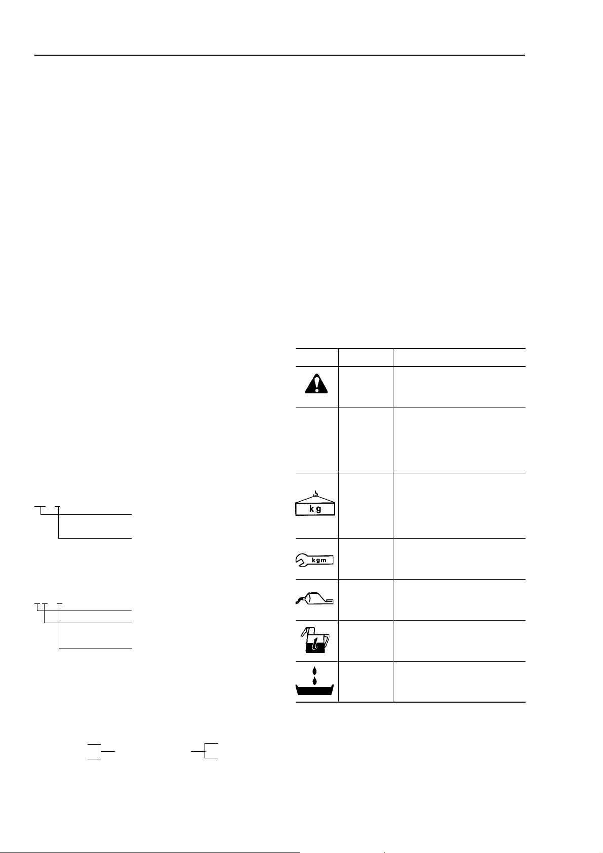
SYMBOLS
So that the shop manual can be of ample practical
use, important safety and quality portions are
marked with the following symbols.
lobmySmetIskrameR
snoituacerpytefaslaicepS
★
ytefaS
noituaC
thgieW
gninethgiT
euqrot
taoC
.cte
retaw,liO
.yticapac
niarD
nehwyrassecenera
.krowehtgnimrofrep
lacinhcetlaicepS
rehtorosnoituacerp
gnivreserprofsnoituacerp
yrassecenerasdradnats
.krowehtgnimrofrepnehw
.smetsysfostrapfothgieW
nehwyrassecennoituaC
ro,eriwgnitsiohgnitceles
sierutsopgnikrownehw
.tce,tnatropmi
laicepseriuqertahtsecalP
gninethgitehtrofnoitnetta
.ylbmessagnirudeuqrot
htiwdetaocebotsecalP
,stnacirbuldnasevisehda
roretaw,lioerehwsecalP
ehtdna,deddaebtsumleuf
retawrolioerehwsecalP
dna,deniardebtsum
.deniardebotytitnauq
00-6
햲
Page 11
FOREWORD HOISTING INSTRUCTIONS
HOISTING INSTRUCTIONS
HOISTING
Heavy parts (25 kg or more) must be
lifted with a hoist, etc. In the DISASSEM-
BLY AND ASSEMBLY section, every
part weighing 25 kg op mroe is indicated
with the symbol
• If a part cannot be smootlhy removed from the
machine by hoisting, the following checks
should be made:
1) Check for removal of all bolts fastening the
part to the relative parts.
2) Check for existence of another part caus-
ing interference with the part to be removed.
WIRE ROPES
1) Use adequate ropes depending on the
weight of parts to be hoisted, referring to
the table below:
seporeriW
seportsiwt"S"ro"Z"dradnatS(
gnizinavlagtuohtiw
)mm(retemaidepoR)snot(daolelbawollA
010.1
2.114.1
5.216.1
412.2
618..2
816.3
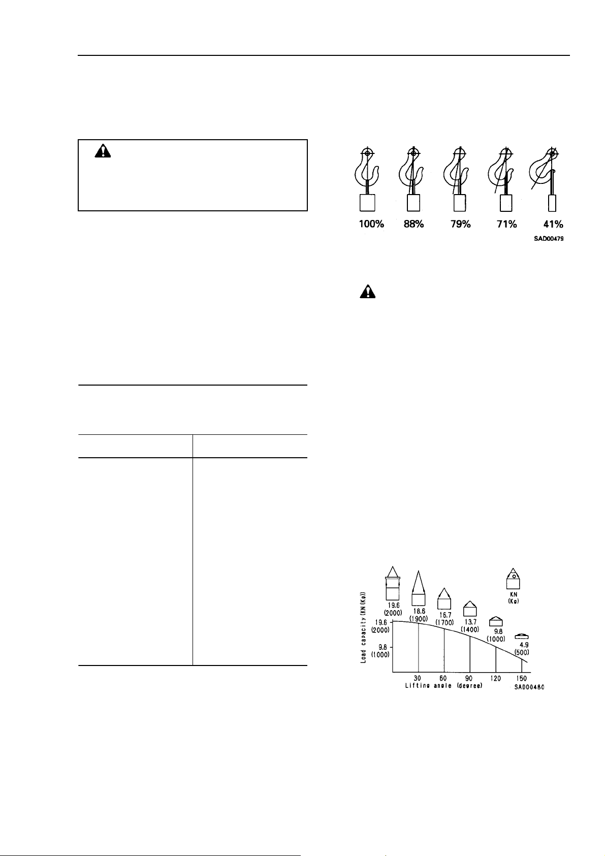
Slinging near the edge of the hook may cause the
rope to slip off the hook during hoisting, and a serious accident can result. Hooks have a maximum
strength at the middle portion.
3) Do not sling a heavy load with one rope alone,
but sling with two or more ropes symmetrically
wound onto the load.
Slinging with one rope may cause turning
of the load during hoisting, untwisting of
the rope, or slipping of the rope from its
original winding position on the load, which
can result in a dangerous accident.
4) Do not sling a heavy load with ropes forming a
wide hanging angle from the hook. When hoisting a load with two or more ropes, the force subjected to each rope will increase with the
nahging angles. The table below shows the
variation of allowable load (kg) when hoisting is
made with two ropes, each of which is allowed
to sling up to 1000 kg vertically , at various hanging angles.
When two ropes sling a load vertically, up to
2000 kg of total weight can be suspended. This
weight becomes 1000 kg when two ropes make
a 120° hanging angle. On the other hand, two
ropes are subjected to an excessive force as
large as 4000 kg if they sling a 2000 kg load at a
lifting angle of 150°.
024.4
4.226.5
030.01
040.81
050.82
060.04
★ The allowable load value is estimated to be
one-sixth or one-seventh of the breaking
strength of the rope used.
2) Sling wire ropes from the middle portion of the
hook.
00-7
햲
Page 12

FOREWROD COA TING MA TERIALS
COA TING MA TERIALS
The recommended coating materials prescribed in Komatsu Shop Manuals are listed below.
Category
Adhesive
Gasket sealant
Rust prevention
lubricant
Molybdenum
disulphide
lubricant
Lithium grease
Calcium grease
Molybdenum
disulphide
grease
Komatsu code
LT-1A
LT-1B
LT-2
LT-3
LT-4
(Loctite 648-50)
LG-1
LG-3
LG-4
LG-5
LG-6
LG-7
-
-
G2-LI
G2-CA
-
Part No.
790-129-9030
790-129-9050
09940-00030
790-129-9060
(Set of adhesive
and hardening
agent)
790-129-9040
79A-129-9110
790-129-9070
790-120-9020
790-129-9080
09940-00011
09920-00150
09940-00051
09940-00040
SYG350LI
SYG-400LI
SYG-400LI-A
SYG-160LI
SYGA-160CNLI
SSG2-400CA
SYG2-350CA
SYG2-400CA-A
SYG2-160CA
SYGA-16NCA
SYG2-400M
Q'ty
150 g
20 g
(x2)
50 g
Adhesive
: 1 kg
Hardening
agent
: 500 g
250 g
50 cc
200 g
1kg
200 g
1 kg
250 g
150 g
60 g
200 g
Various
Various
400 g (10
per case)
Container
Tube
Plastic
container
Plastic
container
Can
Plastic
container
-
Tube
Can
Tube
Plastic
container
Tube
Tube
Can
Tube
Various
Various
Bellows type
Main applications, features
• Used to prevent rubber gaskets, rubber cushions, and
cork plugs from coming out
• Used in places requiring an immediately effective, strong
adhesive. Used for plastics (except polyethylene,
polyprpylene, tetrafluoroethylene and vinyl chloride),
rubber, metal, and non-metal.
• Features: resistance to heat, chemicals
• Used for anti-lossening and sealant purposes for bolts
and plugs
• Used as adhesive or sealant for metal, glass, plastic
• Used as sealant for machined holes
• Features: Resistance to heat, chemicals
• Used at joint portions subject to high temperature
• Used as adhesive or sealant for gaskets and packings of
power train case, etc.
• Features: Resistance to heat
• Used as sealant for flange surfaces and bolts at high
temperature locations, used te prevent seizure
• Used as sealant for heat resistant gasket for high
temperature locations such as engine precombustion
chamber, exhaust pipe
• Features: Resistance to water, oil
• Used as sealant for flange surface, thread
• Aiso possible to use as sealant for flanges with large
clearance
• Used as sealant for mating surfaces of final drive case,
transmission case.
• Used as sealant for various threads, pipe joints, flanges
• Used as sealant for tapered plugs, elbows, nipples of
hydraulic piping
• Features: Silicon based, resistance to heat, cold
• Used as sealant for flange surface, thread
• Used as sealant for oil pan, final drive case, etc.
• Features: Silicon based, quick hardening type
• Used as sealant fo rflywheel housing, intake manifold, oil
pan, thermostat housing, etc.
• Used as lubricant for sliding parts (to prevent squeaking)
• Used to prevent seizure or scuffing of the thread when
presss fitting or shrink fitting
• Used as lubricant for linkage, bearings, etc.
• General purpose type
• Used for normal temperature, light load bearing at places
in contact with water or steam
• Used for places with heavy load
00-8
햲
Page 13
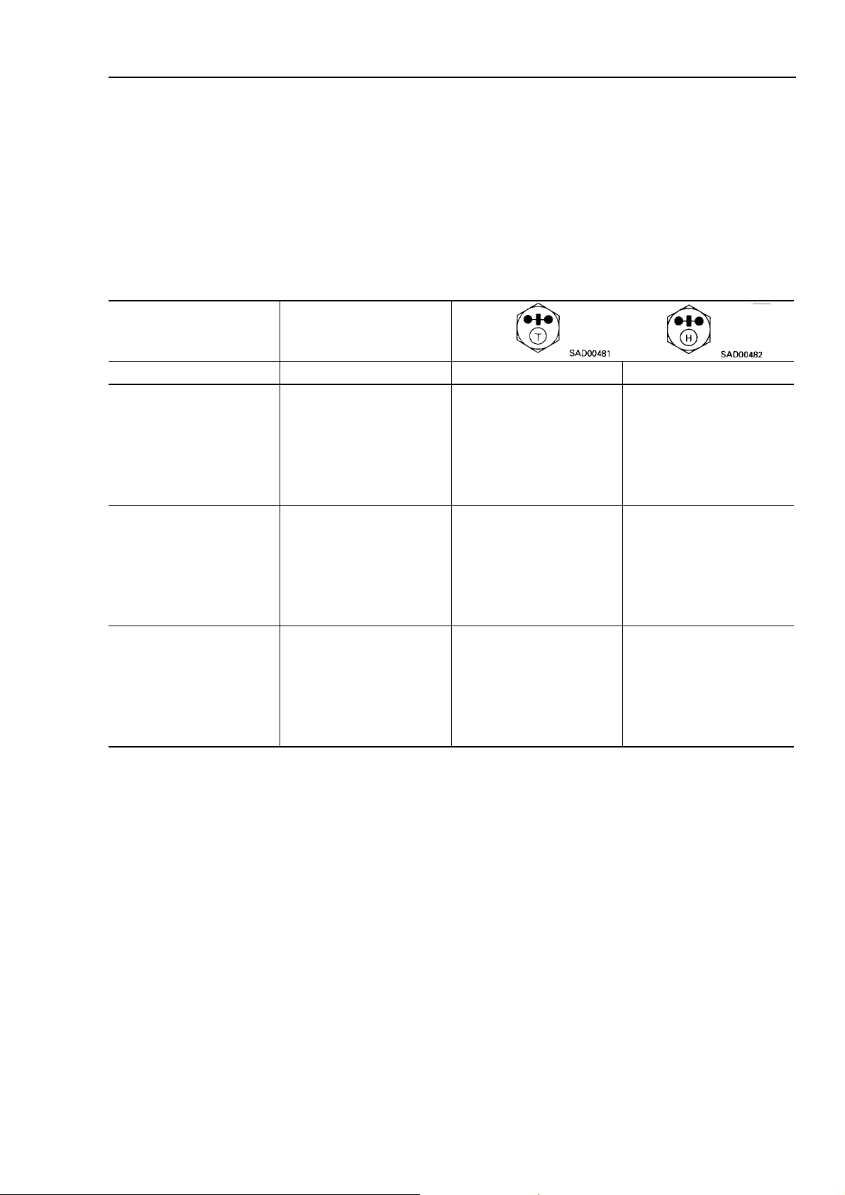
FOREWORD ST ANDARD TIGHTENING TORQUE
ST ANDARD TIGHTENING TORQUE
ST ANDARD TIGHTENING TORQUES OF BOLTS AND NUTS
The following charts give the standard tightening torques of bolts and nuts. Exceptions are given in section of
DISASSEMBL Y AND ASSEMBLY.
1 Kgm = 9.806 Nm
retemaiddaerhT
tlobfo
mmmmmgkmN
60153.1 ± 51.02.31 ± 4.1
8312.3 ± 3.04.13 ± 9.2
01717.6 ± 7.07.56 ± 8.6
21915.11 ± 0.1211 ± 8.9
41220.81 ± 0.2771 ± 91
61425.82 ± 3972 ± 92
817293 ± 4383 ± 93
020365 ± 6945 ± 85
222367 ± 8547 ± 87
42635.49 ± 01729 ± 89
7214531 ± 510231 ± 041
0364571 ± 020271 ± 091
3305522 ± 520122 ± 042
6355082 ± 030572 ± 092
htdiW
stalfssorca
9306533 ± 520823 ± 043
★ This torque table does not apply to the bolts with nylon packaging or other nonferrous metal wash-
ers are to be used, or which require tightening to otherwise specified torque.
00-9
햲
Page 14
FOREWORD ST ANDARD TIGHTENING TORQUE
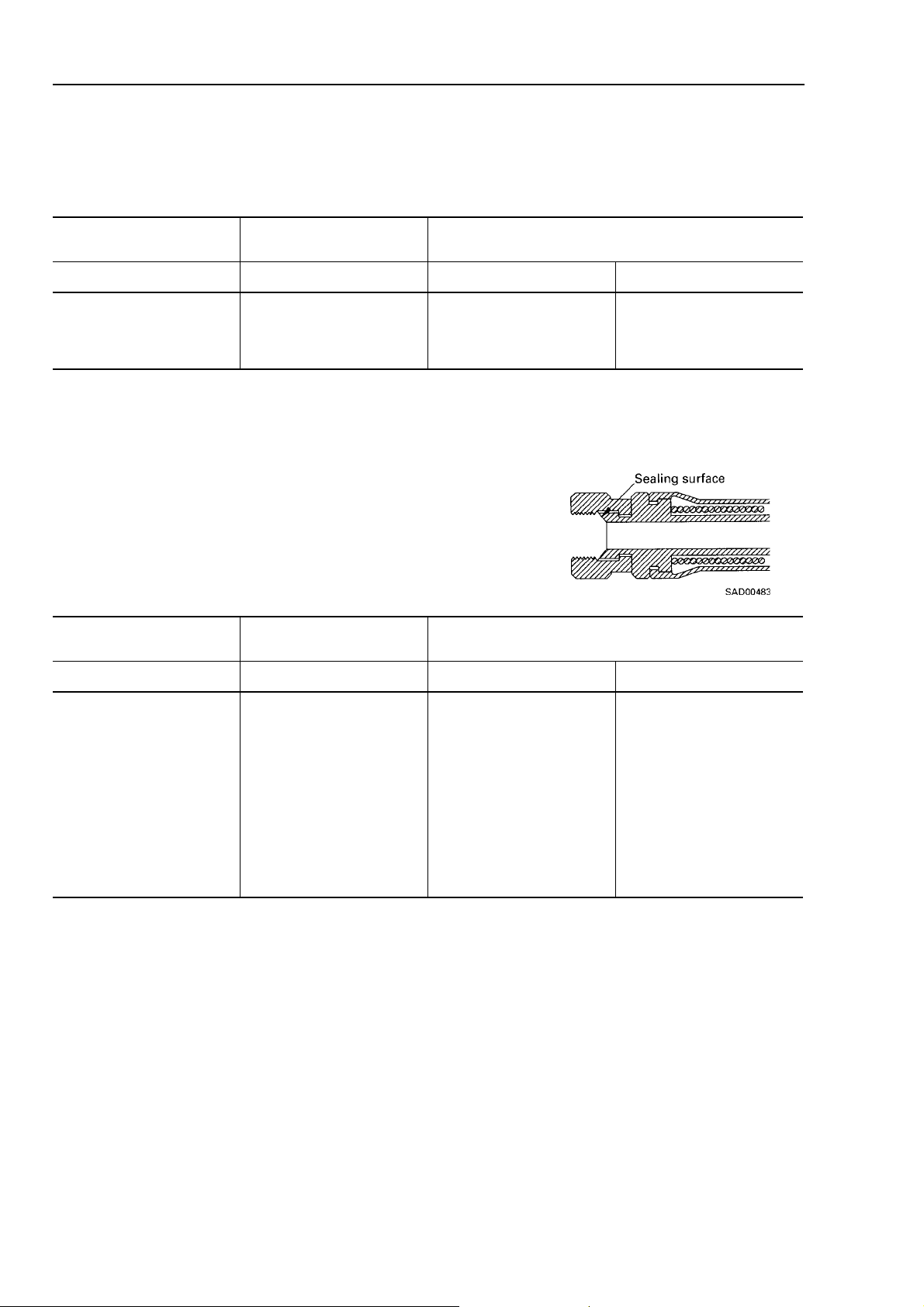
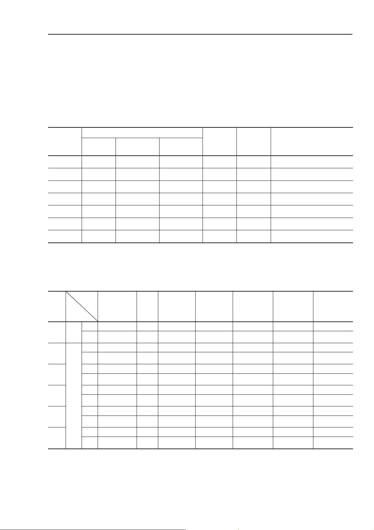
TIGHTENING TORQUE OF SPLIT FLANGE BOLTS
Use these torques for split flange bolts.
retemiaddaerhT
tlobfo
mmmmmgkmN
01417.6 ± 7.07.56 ± 8.6
21715.11 ± 1211 ± 8.9
61225.82 ± 3972 ± 92
TIGHTENING TORQUE FOR FLRED NUTS
Use these torques for flared part of nut.
retemiaddaerhT
tlobfo
mmmmmgkmN
htdiW
stalfssorca
htdiW
stalfssorca
euqrotgninethgiT
euqrotgninethgiT
41915.2 ± 5.05.42 ± 9.4
81425± 294 ± 6.91
22728± 25.87 ± 6.91
422341 ± 33.731 ± 4.92
036381 ± 35.671 ± 4.92
331402 ± 51.691 ± 94
636452 ± 52.542 ± 94
245503 ± 52.492 ± 94
00-10
햲
Page 15
FOREWORD ELECTRIC WIRE CODE
ELECTRIC WIRE CODE
In the wiring diagrams, various colors and symbols are employed to indicate the thickness of wires. This
wire code table will help you understand WIRING DIAGRAMS.
Example: 5WB indicates a cable having a nominale number 5 and white coating with black stripe.
CLASSIFICA TION BY THICKNESS
lanimoN
rebmun
forebmuN
sdnarts
fo.aiD
)mm(sdnarts
noitcesssorC
)2mm(
elbaC
)mm(.D.O
58.01123.088.04.221.ctelangis,gnithgil,gnitratS
26223.090.21.302.ctelangis,gnithgiL
55623.032.56.473langisdnagnigrah
514854.063.310.795)gulpwolG(gnitratS
045808.037.244.11531gnitratS
0672108.048.366.31871gnitratS
00171208.01.9016.71032gnitratS
CLASSIFICATION BY COLOR AND CODE
stiucriC
eriwreppoC
-roirP
yti
1
2
3
4
5
6
-salC
noitacifis
-irP
yrail
edoCWBB R Y G L
yram
roloCetihWkcalBkcalBdeRwolleYneerGeulB
edoCRW-WBWRRYWGWL
roloCdeR&etihW- etihW&kcalBetihW&deRdeR&wolleYetihW&neerGetihW&eulB
edoCBW-YBBRBYRGRL
roloCkcalB&etihW- wolleY&kcalBkcalB&deRkcalB&wolleYdeR&neerGdeR&eulB
edoCLW-RBYRGYYGYL
-ixuA
roloCeulB&etihW-deR&kcalBwolleY&deRneerG&wolleYwolleY&neerGwolleY&eulB
edoCGW-- GRLYBGBBL
roloCneerG&etihW-- neerG&deReulB&wolleYkcalB&neerGkcalB&eulB
edoC--- LRWYLG-
roloC--- eulB&deRetihW&wolleYeulB&neerG-
gnigrahCdnuorGgnitratSgnithgiLtnemurtsnIlangiSrehtO
tnerruC
)A(gnitar
tiucricelbacilppA
00-11
햲
Page 16
FOREWORD CONVERSION T ABLE
CONVERSION T ABLE
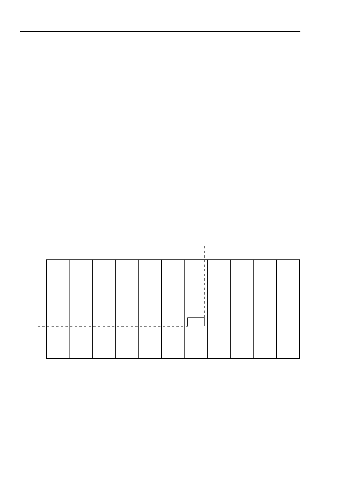
METHOD OF USING THE CONVERSION T ABLE
The Conversion T able in this section is provided to enable simple conversion of figures. For details of the method
of using the Conversion Table, see the example given below.
EXAMPLE
• Method of using the Conversion Table to convert from millimeters to inches
1. Convert 55 mm to inches
(1) Locate the number 50 in the vertical column at the left side, take this as 훽, then draw a horizontal line
from 훽.
(2) Locate the number 5 in the row across the top, take this as 훾, then draw a perpendicular line down
from 훾.
(3) Take the point where the two lines cross as 훿. This pint 훿 gives the value when converting from
millimeters to inches. Therefore, 55mm = 2.165 inches.
2. Convert 550 mm into inches.
(1) The nuber 550 does not appear in the table, so divide by 10 (move the decimal point one place to the
left) to convert it to 55 mm.
(2) Carry out the same procedure as above to convert 55 mm to 2.165 inches.
(3) The original value (550 mm) was divided by 10, so multiply 2.165 inches by 10 (move the decimal point
one place to the right) to return to the orginal value. This gives 550 mm = 21.65 inches.
훾
Millimeters to inches 1 mm = 0.03937 in
0123456789
00 930.0970.0811.0751.0791.0632.0672.0513.0453.0
01493.0334.0274.0215.0155.0195.0036.0966.0907.0847.0
02787.0728.0668.0609.0549.0489.0420.1360.1201.1241.1
03181.1022.1062.1992.1933.1873.1714.1754.1694.1635.1
04575.1416.1456.1396.1237.1277.1118.1058.1098.1929.1
훿
훽
05969.1800.2740.2780.2621.2561.2502.2442.2382.2323.2
06263.2204.2144.2084.2025.2955.2895.2836.2776.2717.2
07657.2597.2583.2478.2319.2359.2299.2230.3170.3011.3
08051.3981.3822.3862.3703.3643.3683.3524.3564.3405.3
09345.3385.3226.3166.3107.3047.3087.3918.3858.3898.3
00-12
햲
Page 17
FORWORD CONVERSION T ABLE
Millimeters to Inches
1 mm = 0.03937 in
0123456789
00930.0970.0811.0751.0791.0632.0672.0513.0453.0
01493.0334.0274.0215.0155.0195.0036.0966.0907.0847.0
02787.0728.0668.0609.0549.0489.0420.1360.1201.1241.1
03181.1022.1062.1992.1933.1873.1714.1754.1694.1635.1
04575.1416.1456.1396.1237.1277.1118.1058.1098.1929.1
05969.1800.2740.2780.2621.2561.2502.2442.2382.2323.2
06263.2204.2144.2084.2025.2955.2895.2836.2776.2217.2
07657.2597.2538.2478.2319.2359.2299.2230.3170.3011.3
08051.3981.3822.3862.370.33643.3683.3524.3564.3405.3
09345.3385.3226.3166.3107.3047.3087.3918.3858.3898.3
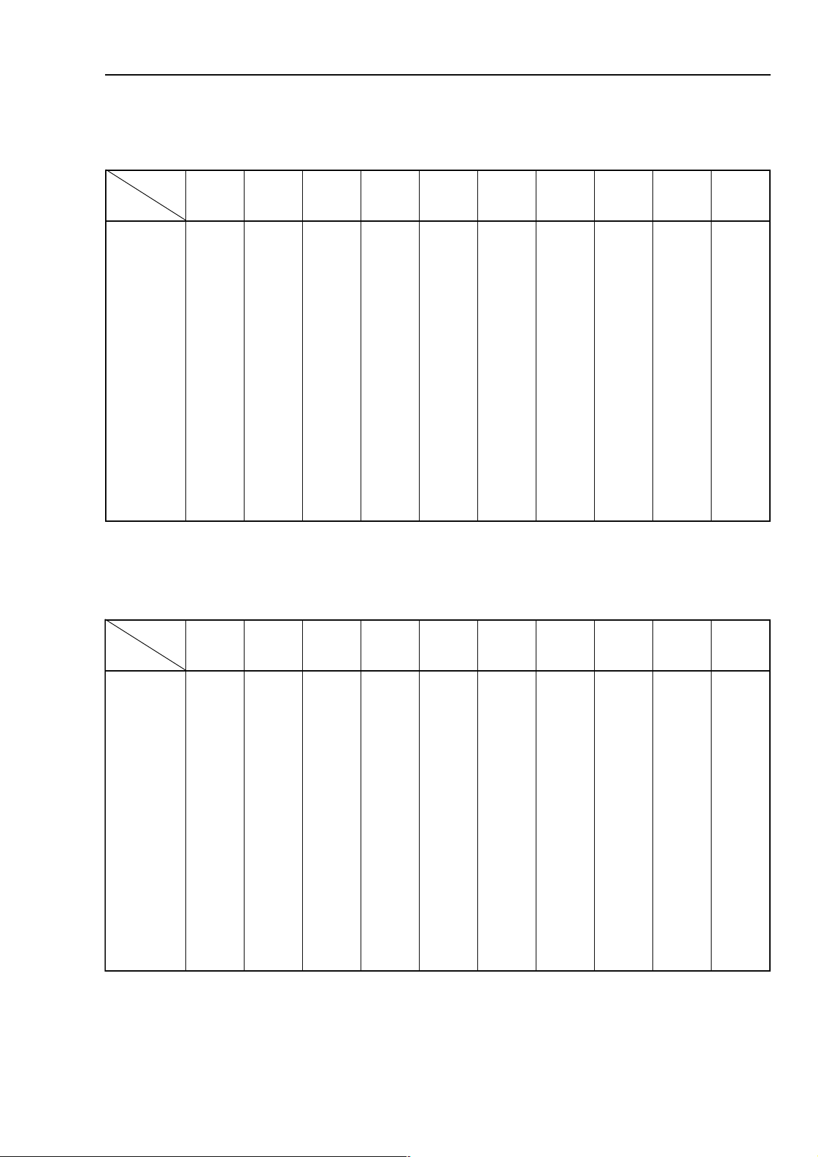
Kilogram to Pound
0123456789
0002.214.416.628.820.1132.3134.5146.7148.91
0150.2252.4264.6266.8268.0370.3372.5384.7386.9398.14
0290.4403.6405.8417.0519.1521.5523.7535.9537.1639.36
0341.6643.8655.0757.2769.4761.7773.9775.1887.3889.58
0481.8893.0995.2908.4900.7912.9914.10126.30128.50130.801
0532.01144.21146.41158.61150.91152.12164.32166.53178.72170.031
0682.23184.43196.63198.83101.14103.34115.54117.74119.94121.251
1kg = 2.2046 lb
0723.45135.65137.85149.06141.36153.56155.76167.96169.17171.471
0873.67175.87187.08189.28191.58193.78106.98108.19110.49112.691
0924.89126.00230.20230.50242.70244.90246.11258.31250.61262.812
00-13
햲
Page 18
FORWORD CONVERSION T ABLE
Litre to U.S. Gallon
1l = 0.2642 U.S. Gal
0123456789
00462.0825.0397.0750.1123.1585.1948.1311.2873.2
01246.2609.2071.3434.3896.3369.3722.4194.4557.4910.5
02382.5845.5218.5670.60433.6406.6968.6331.7793.7166.7
03529.7981.8454.8817.8289.8642.9015.9477.9930.01303.01
04765.01138.01590.11953.11426.11888.11251.21614.21086.21449.21
05902.31374.31737.31100.41562.41925.41597.41850.51223.51685.51
06058.51511.61973.61346.61709.61171.71534.71007.71469.71822.81
07294.81657.81020.91582.91945.91318.91770.02143.02506.02078.02
08431.12893.12266.12629.12091.22554.22917.22389.22742.32115.32
09577.32040.42403.42865.42238.42690.52163.52526.52988.52351.62
Litre to U.K. Gallon
1l = 0.21997 U.K. Gal
0123456789
00022.0044.0066.0088.0001.1023.1045.1067.1089.1
01002.2024.2046.2068.2080.3003.302.53047.3059.3971.4
02993.4916.4938.4950.5972.5994.5917.5939.5951.69736
03995.6918.6930.7952.7974.7969.7919.7931.8953.8975.8
04997.8910.9932.9954.9976.9998.9911.01933.01955.01877.01
05899.01182.11834.11856.11878.11890.21813.21825.21857.21879.21
06891.31814.31836.31858.31870.41892.41815.41837.41859.41871.51
07893.51816.51838.51850.61872.61894.61817.61839.61851.71873.71
08895.71818.71730.81752.81774.81796.81719.81731.91753.91775.91
09797.91710.02732.02754.02776.02798.02711.12733.12755.12777.12
00-14
햲
Page 19
FORWORD CONVERSION T ABLE
kgm to ft. lb
1 kgm = 7.233 ft. lb
0123456789
002.75.417.129.822.634.346.059.751.56
013.276.978.680.493.1015.8017.5110.3212.0314.731
027.4419.1511.9514.6616.3718.0811.8813.5915.2028.902
030.7122.4225.1327.8329.5422.3524.0626.7629.4721.282
043.9826.6928.3030.1133.8135.5237.2330.0432.7434.453
057.1639.8631.6734.3836.0938.7931.5043.2145.9148.624
060.4342.1445.8447.5549.2642.0744.7746.4848.1941.994
073.6055.3158.0250.8252.5355.2457.9459.6552.4654.175
086.8759.5851.3953.0066.7068.4160.2263.9265.6367.346
090.1562.8564.5667.2769.9761.7864.4966.1078.8071.617
0013.3275.0378.7370.5472.2575.9577.6679.3772.1874.887
0116.5979.2081.0183.7186.4288.1380.9383.6485.3587.068
0210.8682.5784.2887.9889.6981.4094.1196.8198.5291.339
0313.0495.7498.4590.2692.9695.6797.3899.0992.8994.5001
0416.21019.91011.72013.43015.14018.84010.65012.36015.07017.7701
0519.48012.29014.99016.60119.31111.12113.82116.53118.24110.0511
0613.75115.46117.17110.97112.68114.39117.00219.70211.51214.2221
0716.92118.63211.44213.15215.85218.56210.37211.08215.78217.4921
0819.10312.90314.61316.32319.03311.83313.54216.25318.95310.7631
0913.47315.18317.88310.69312.30414.01417.71419.42411.23414.9341
00-15
햲
Page 20
FORWORD CONVERSION T ABLE
kg/cm
2
to lb/in
2
1 kg/cm2 = 14.2233 lb/in
0123456789
002.414.827.249.651.173.586.998.3110.821
012.2415.6517.0719.4811.9914.3126.7228.1420.6522.072
025.4827.8929.2131.7234.1436.5538.9630.4833.8935.214
037.6249.0441.5544.9646.3848.7940.2153.6255.0457.455
049.8652.3854.7956.1168.5261.0463.4565.8667.2869.696
052.1174.5276.9378.3571.8673.2875.6977.0180.5282.938
064.3586.7688.1881.6983.0195.4297.8390.3592.7694.189
076.599010142018301350176011801590190114211
088311251166111811591190213221732125216621
090821492190313231733115315631083149318041
2
0012241734115415641974139418051225163510551
0115651975139517061126163610561466187613961
0217071127153719471467187712971608112815381
0319481368177812981609102914391949136917791
0411991500202024302840226027702190250129112
0514312841226126712091250229122332274222622
0616722092240328132333274321632573298324042
0718142234264420642574298423052815223526452
0810652475298523062716113626462066247628862
0912072717213725472957237728872208261820382
0025482958237827882109261920392449285923792
0127892100351030303440385032703680310135113
0229213341385132713681300234123922334237523
00-16
햲
0321723682300334133823334337533174458339933
0424143824324436543074358439943315372532453
Page 21

FORWORD CONVERSION T ABLE
Temperature
Fahrenheit-Centigrade Conversion; a simple way to convert a Fahrenheit temperature reading into a Centigrade
temperature reading or vice is to enter the accompanying table in the center or boldface column of figures.
These figures refer to the temperature in either Fahrenheit or Centigrade degrees.
If it desired to convert from Fahrenheit to Centigrade degrees, consider the center column as a table of Fahrenheit temperatures and read the corresponding Centigrade temperature in the column at the left.
If it is desired to convert from Centigrade to Fahrenheit degrees, consider the center column as a table of
Centigrade values, and read the corresponding Fahrenheit temperature on the right.
1°C = 33.8°F
°C °F °C °F °C °F °C °F
4.04-04-0.04-7.11-118.158.7648.4112.72188.711
2.73-53-0.13-1.11-216.353.8746.6118.72286.971
4.43-03-0.22-6.01-314.559.8844.8113.82384.181
7.13-52-0.31-0.01-412.754.9942.0219.82482.381
9.82-02-0.4-4.9-510.950.01050.2214.92580.581
3.82-91-2.2-9.8-618.066.01158.3210.03688.681
8.72-81-4.0-3.8-716.261.11256.5216.03786.881
2.72-71-4.18.7-814.467.11354.7211.13884.091
7.62-61-2.32.7-912.662.21452.9217.13982.291
1.62-51-0.57.6-020.868.21550.1312.23090.491
6.52-41-8.61.6-128.963.31658.2318.23198.591
0.52-31-6.86.5-226.179.31756.4313.33296.791
4.42-21-4.010.5-324.374.41854.6319.33304.991
9.32-11-2.214.4-424.370.51952.8314.43492.102
3.32-01-0.419.3-522.576.51060.0410.53590.302
8.22-9-8.513.3-620.771.61168.1416.53698.402
2.22-8-6.718.2-728.877.61266.3411.63796.602
7.12-7-4.912.2-826.082.71364.5417.63894.802
1.12-6-2.127.1-924.288.71462.7412.73992.012
6.02-5-0.321.1-030.683.81560.9418.730010.212
0.02-4-8.426.0-138.789.81668.0516.045010.122
4.91-3-6.620236.984.91766.2513.340110.032
9.81-2-4.826.0334.190.02864.4511.645110.932
3.81-1-2.031.1432.396.02962.6519.840210.842
8.71-00.237.1530.591.12070.8517.155210.752
2.71-18.332.2638.697.12178.9514.450310.662
7.61-26.538.2736.892.22276.1612.755310.572
1.61-34.733.3834.0018.22374.3610.060410.482
6.51-42.939.3932.2013.32472.5617.265410.392
0.51-50.144.4040.4019.32570.7616.560510.203
4.41-68.240.5148.5014.42678.8613.865510.113
9.31-76.446.5246.7010.52776.0711.170610.023
3.31-84.641.6344.9016.52874.2719.375610.923
8.21-92.847.6442.1111.62972.4717.670710.833
2.21-010.052.7540.3117.62080.6714.975710.743
00-17
햲
Page 22

00-18
햲
Page 23

STRUCTURE AND FUNCTION
10 STRUCTURE AND FUNCTION
ENGINE RELATED PARTS ...................... 10-2
RADIATOR & OIL COOLER...................... 10-3
PTO........................................................... 10-4
POWER TRAIN......................................... 10-5
SWING CIRCLE........................................ 10-7
SWING MACHINERY ............................... 10-8
UNDERCARRIAGE................................... 10-9
TRANSMISSION....................................... 10-11
CLUTCH CONTROL ................................. 10-13
AXLE ......................................................... 10-15
SUSPENSION LOCK CYLINDER............. 10-19
BRAKING TRAIN ...................................... 10-21
BRAKE & STEERING CIRCUIT................ 10-22
BRAKE/STEERING PUMP ....................... 10-25
BRAKE PEDAL/BRAKE VALVE................ 10-26
PRIORITY VALVE ..................................... 10-27
ACCUMULATOR FOR BRAKE SYSTEM . 10-28
STEERING TRAIN .................................... 10-29
STEERING COLUMN ............................... 10-31
ORBITROL VALVE.................................... 10-32
HYDRAULIC CIRCUIT DIAGRAM ............ 10-33
FUEL/HYDRAULIC T ANK......................... 10-35
HYDRAULIC PUMP .................................. 10-36
LS VALVE/PC VALVE................................ 10-42
PPC PUMPLESS SYSTEM ...................... 10-56
CONTROL VALVE..................................... 10-58
CLSS......................................................... 10-68
SWING MOTOR........................................ 10-98
CENTER SWIVEL JOINT ......................... 10-103
TRAVEL MOTORS.................................... 10-104
WORK EQUIPMENT -
SWING PPC VALVE ................................. 10-110
TRAVEL PPC PEDAL ............................... 10-114
SERVICE PPC PEDAL ............................. 10-113
SAFETY LOCK SWITCH .......................... 10-117
PPC MANIFOLD BLOCK .......................... 10-118
PPC MANIFOLD BLOCK
PRESSURE SWITCHES .......................... 10-119
SOLENOID VALVE ................................... 10-120
TRAVEL SPEED - SWING BRAKE 2-STAGE RELIEF SUSPENSION
SOLENOID VALVE ................................... 10-121
BOOM SAFETY VALVE ............................ 10-122
HYDRAULIC CYLINDERS
(BOOM, ARM & BUCKET)........................ 10-125
OUTRIGGER CYLINDER ......................... 10-127
DOZER BLADE CYLINDER...................... 10-128
WORK EQUIPMENT................................. 10-129
ELECTRICAL WIRING DIAGRAM............ 10-130-1
ENGINE CONTROL SYSTEM .................. 10-131
MACHINE MONITOR SYSTEM................ 10-160
OVERLOAD WARNING DEVICE ............. 10-167
BREAKER MODE HYDRAULIC
PERFORMANCE ...................................... 10-168
10-1
Page 24
STRUCTURE AND FUNCTION
ENIGNE RELATED PARTS
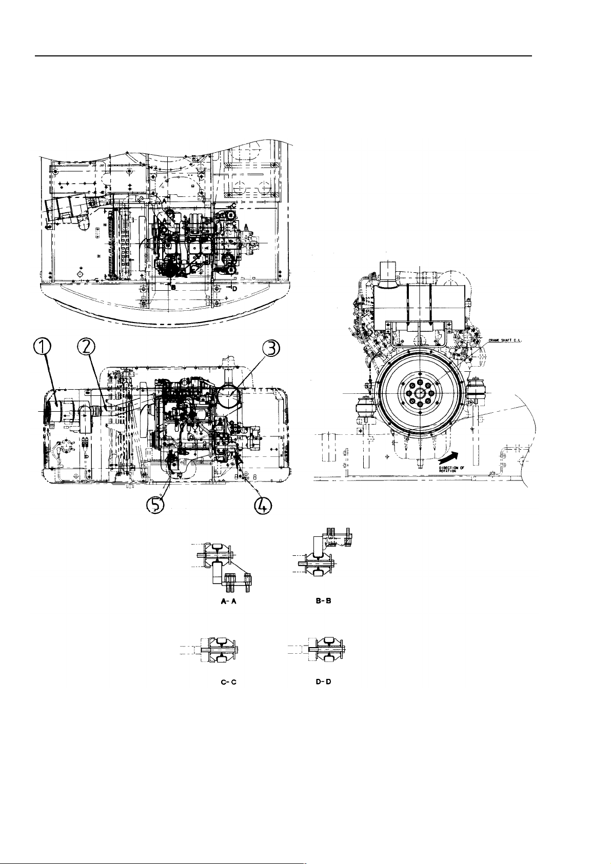
ENGINE RELATED PARTS
1. Air cleaner
2. Intake hose
3. Muffler
4. Rear engine mount
5. Front engine mount
10-2
Page 25
STRUCTURE AND FUNCTION
RADIATOR AND OIL COOLER
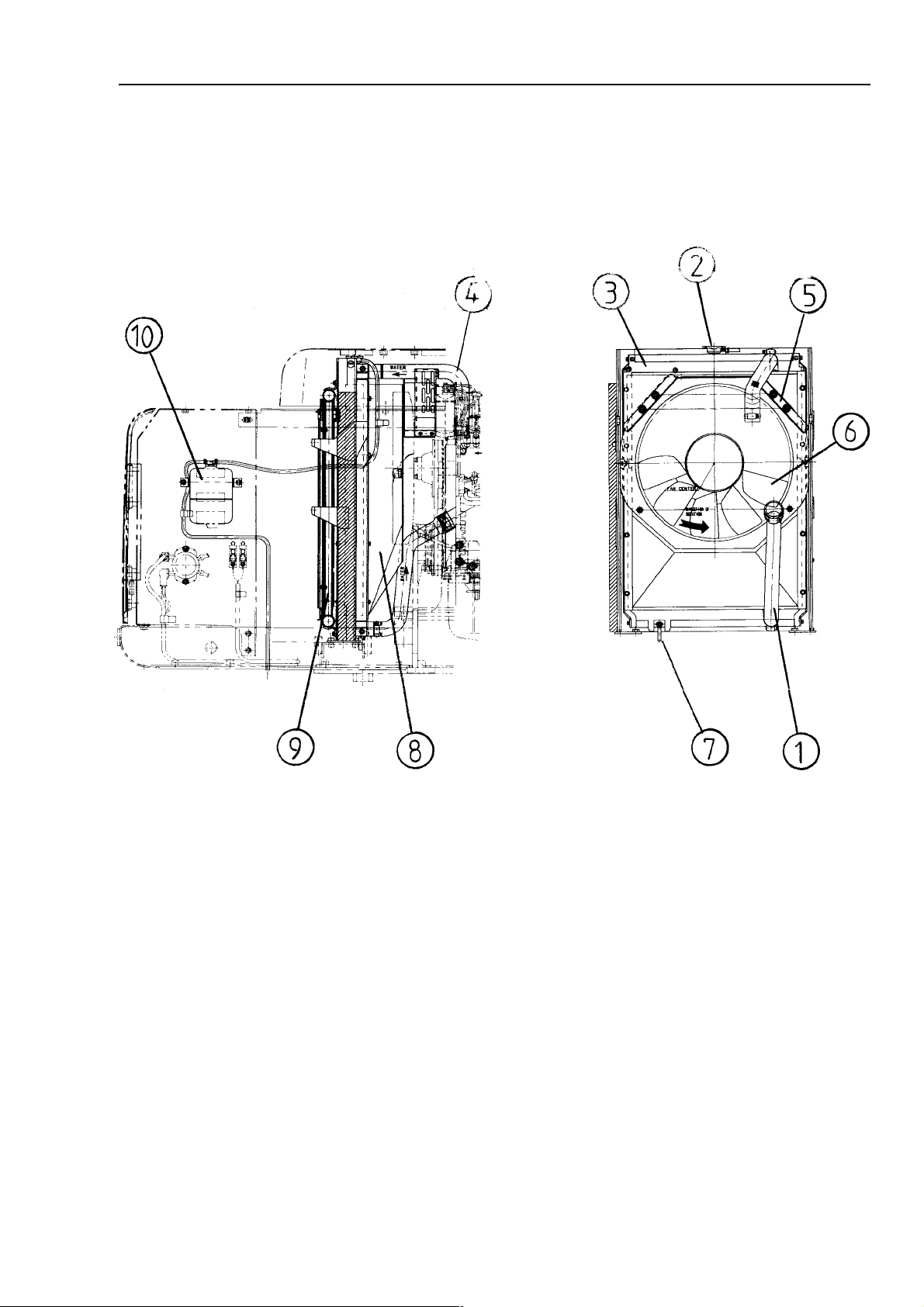
RADIATOR AND OIL COOLER
SPECIFICATIONS
RADIATOR
- Core type: CWX-4
- Fin pitch: 3.5/2 mm
- Total radiation area: 40.37 m
- Pressure valve cracking pressure:
0.05 MPa (0.5 kg/cm2)
- Vacuum valve cracking pressure:
-0.005 MPa (-0.05 kg/cm2)
OIL COOLER
- Core Type: CF40-1
- Fin pitch: 4.5/2 mm
- Total radiation area 10.41 m
2
2
1. Radiator outlet hose
2. Radiator cap
3. Radiator
4. Radiator inlet hose
5. Fan guard
6. Fan
7. Drain valve
8. Shroud
9. Oil cooler
10. Reservoirtank
10-3
Page 26
STRUCTURE AND FUNCTION
PTO (COUPLING)
PTO (COUPLING)
1. Shaft
2. Coupling
3. Breather
4. Cage
5. Hydraulic pump
6. Oil filler plug
7. Level plug
10-4
Page 27
STRUCTURE AND FUNCTION
POWER TRAIN - 20 Km/h TRAVEL SPEED SPEC.
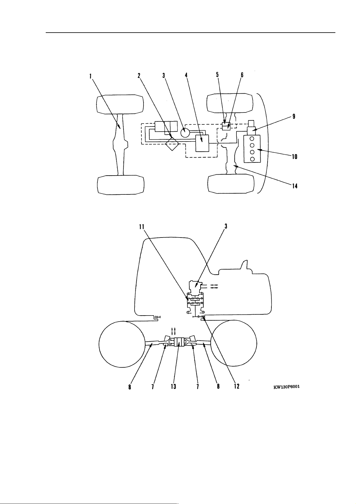
POWER TRAIN
1. Front axle
2. Center swivel joint
3. Swing motor
4. Control valve
5. Swing brake solenoid valve
6. Travel speed solenoid valve
7. Travel motor
8. Propshaft
9. Hydraulic pump
10. Engine
11. Swing machinery
12. Swing circle
13. Transmission
14. Rear axle
10-5
Page 28
STRUCTURE AND FUNCTION
POWER TRAIN - 30 Km/h TRAVEL SPEED SPEC.
18
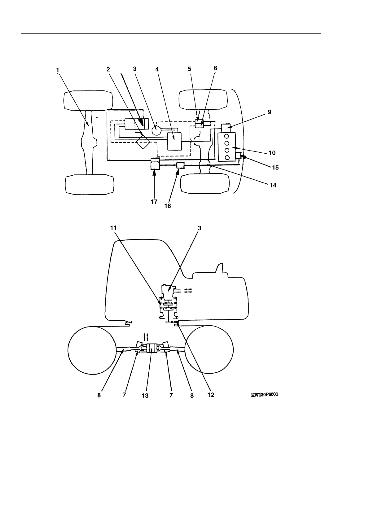
POWER TRAIN
1. Front axle
2. Center swivel joint
3. Swing motor
4. Control valve
5. Swing brake solenoid valve
6. Travel speed solenoid valve
7. Travel motor
8. Propshaft
9. Hydraulic pump
10-6
10. Engine
11. Swing machinery
12. Swing circle
13. Transmission
14. Rear axle
15. Gear pump
16. Priority valve
17. Power brake valve
18. Clutch
Page 29
STRUCTURE AND FUNCTION
SWING CIRCLE
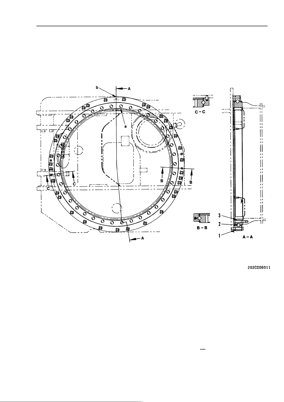
SWING CIRCLE
1. Outer race
2. Ball
3. Inner race
a. Inner race soft zone "S" position
b. Outer race soft zone "S" position
Specifications
Reduction ratio:
Amount of grease: 10 l (Grease: (G2-LI)
90
= 8.182
11
10-7
Page 30
STRUCTURE AND FUNCTION
SWING MACHINERY
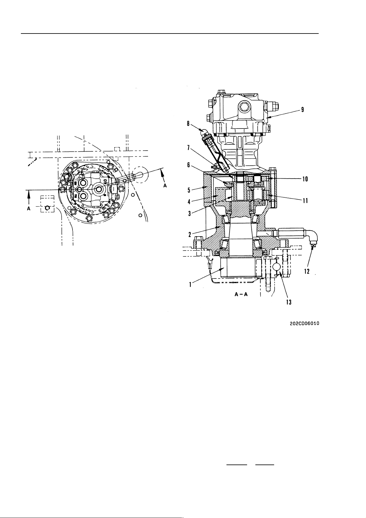
SWING MACHINERY
1. Swing pinion (No. of teeth:11)
2. Case
3. No. 2 sun gear (No. of teeth: 17)
4. No. 2 planetary carrier (No. of teeth: 17)
5. Ring gear (No. of teeth:61)
6. No. 1 planetary carrier (No. of teeth: 17)
7. No. 1 sun gear (No. of teeth: 14)
8. Oil level gauge/oil filler port
9. Swing motor
10-8
10. No. 1 planetary gear (No. of teeth: 24)
11. No. 2 planetary gear (No. of teeth: 22)
12. Drain plug
13. Swing circle
Specification
Reduction ratio
14 + 61 x 17 +61
14 17
= 24.586
Page 31

UNDERCARRIAGE
UNDERCARRIAGESTRUCTURE AND FUNCTION
1. Undercarriage
2. Step
3. Wheel chock
4. Front oscillating steering axle
5. Rear axle
6. Propshaft
7. Travel motor
8. Transmission
9. Double wheel ass'y
10. Single wheel ass'y
10-9
Page 32

STRUCTURE AND FUNCTION
10-10
Page 33

STRUCTURE AND FUNCTION
TRANSMISSION - 20 Km/h TRAVEL SPEED SPEC.
TRANSMISSION
1. Screw-fork to shaft
2. Flange
3. Brake cylinder
4. Brake drum
5. Friction disk
6. Flange
7. Gear
8. Cover
9. Output shaft
10. Bearing
11. Gear
Specification
Reduction ratio: 2.265 : 1
10-11
Page 34

TRANSMISSIONSTRUCTURE AND FUNCTION
TRANSMISSION - 30 Km/h TRAVEL SPEED SPEC.
CLUTCH ASS'Y - 30 Km/h TRAVEL SPEED SPEC.
1. Screw-fork to shaft
2. Flange
3. Brake cylinder
4. Brake drum
5. Friction disk
6. Flange
7. Gear
8. Cover
9. Output shaft
10. Bearing
11. Gear
12. Clutch ass'y
Specification
Reduction ratio: 1.846 : 1
1. Casing
2. Drive shaft
3. Friction plates
4. Spring discs
5. Gear
6. Clutch control gear pump
7. Plug
8. Plug
10-12
Page 35

STRUCTURE AND FUNCTION
CLUTCH CONTROL CIRCUIT (30 Km/h SPEC. ONLY)
CLUTCH
STRUCTURE
1. Clutch control pump
2. Clutch control valve
10-13
Page 36

STRUCTURE AND FUNCTION
FUNCTION
The clutch is a device which automatically disengages the drive between the large diplacement
(Rear) travel motor and the transmission. This occurs when the machine is accelerating and the disengagement occurs at 11 Kph. The transmission
system becomes more efficient (by reducing losses
caused by the unnecessary rotation of the rear
travel motor) providing better acceleration and enabling a maximum speed of 30 Kph.
When the machine decelerates from a high speed
the clutch will re-engage automatically at 9 Kph and
will remain engaged until the speed is increased
above 11 Kpm again.
CLUTCH
10-14
Page 37

STRUCTURE AND FUNCTION
AXLE
OUTLINE
• Each axle consists of an axle housing supporting the chassis weight, a differential set in the
axle housing, a final drive, and a brake provided
at each end.
• A trunnion-type axle shaft with a king pin at the
final drive end is used to enable the direction of
travel of the machine to be changed.
FRONT AXLE
AXLE
10-15
Page 38

STRUCTURE AND FUNCTION
REAR AXLE
AXLE
10-16
Page 39

STRUCTURE AND FUNCTION
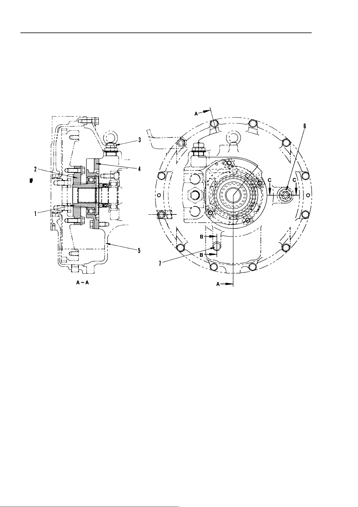
FRONT AXLE
AXLE
Axle reduction ratio = 17,73 : 1
1. Planetary carrier
2. Washer
3. Brake drum
4. Pin
5. Seal ring
6. Grease nipple
7. Seal ring
8. Seal ring
9. Bushing
10. Axle tube
11. Ring nut
12. Ball bearing
13. Ring nut
14. Ball bearing
15. Seal ring
16. Roller bearing
17. Roller bearing
18. Hexagon head screw
19. Shaft
20. Joint
21. Bushing
22. Grease nipple
23. Seal ring
24. Cylinder head screw
25. Roller bearing
26. Washer
27. Ring
28. Hexagon head screw
29. Sun gear
10-17
Page 40

STRUCTURE AND FUNCTION
REAR AXLE
AXLE
1. Planetary gear
2. Bolt
3. Planetary carrier
4. Stud
5. Wheel Hub
6. Bushing
7. Socket
8. Shaft
9. Axle tube
10. Ring nut
11. Roller bearing
12. Roller bearing
10-18
13. Shim
14. Bolt
15. Cover
16. Seal ring
17. Roller bearing
18. Roller bearing
19. Bevel gear
20. Cylinder head screw
21. Bearing
22. Ring gear plate
23. Sun gear
Page 41

STRUCTURE AND FUNCTION
SUSPENSION LOCK CYLINDER
SUSPENSION LOCK CYLINDER
1. Barrel
2. Plunger
Specifications
Piston: ø 85 mm
Stoke: 160 mm
Operating pressure: 40.0 MPa (408 kg/cm
Pilot pressure: 3.0 MPa (30.6 kg/cm2)
Max 5.0 MPa (51.0 kg/cm2)
2
)
10-19
Page 42

STRUCTURE AND FUNCTION
CIRCUIT
SUSPENSION LOCK CYLINDER
Purpose
The undercarriages of wheeled hydraulic excavators have one of the two driven axles oscillating
mounted. This makes it possible to fully utilize the
excavator's rimpull in rough terrain - all of the
wheels being constantly in contact with the ground.
An oscillation blocking ram is fitted on each side of
the undercarriage to block the axle during digging or
lifting work.
Blocking the axle increases the excavator's stability .
1. Ram
2. Axle oscillation point
3. Oscillating axle
4. Oscillation lock solenoid valve
5. Pilot pressure reducing valve
6. Hydraulic tank
7. Swivel joint
8. Check valve
Function
The oscillating axle (3) is mounted in bearing (2) in
the middle of the excavator. The two rams (1) which
are full of hydraulic oil are connected through pipelines to the oscillation lock solenoid valve (4).
When the excavator is being moved, the oscillation
lock solenoid valve should be de-energized so that
the hydraulic oil in the ram can be returned to tank
as the axle is oscillating up and down. Before commencing excavating operations, the oscillation lock
solenoid valve should be energized to pressurize
the oil in the rams. This will lock the axle in the position it is in.
10-20
Page 43

STRUCTURE AND FUNCTION BRAKING TRAIN
1. Hydraulic oil filter
2. Hydraulic oil pump (shared with steering system)
3. Priority valve
4. Brake control valve
5. Accumulator - service brake
6. Accumulator - service brake
7. Accumulator - parking brake
8. Pressure switch - stop light
9. Pressure switch - accumulator
10. Pressure switch - parking brake
11. Pressure switch - service brake
12. Brake pedal
13. Swivel joint
14. Service brake cylinder
15. Service brake cylinder
16. Parking brake cylinder
Structure and function
The brake system is fully hydraulic. Oil is supplied at high pressure by a pump to a priority valve. The priority valve gives
priority to the steering circuit. When braking, oil is sent to the brake valve which provides braking pressure to two separate
braking circuits (service brakes). In the event of a failure of the power supply, the accumulators provide brake pressure to
allow the machine to be safety stopped.
A parking brake is provided which is operated by energizing a solenoid valve in the brake valve which sends pressure to the
park brake in the transmission. Park brake on solenoid off.
10-21
Page 44

STRUCTURE AND FUNCTION BRAKE & STEERING CIRCUIT
BRAKE & STEERING CIRCUIT (ITALIAN SPECIFICATION)
10-22
Page 45

STRUCTURE AND FUNCTION
Function
The function of the steer/brake circuit (Italian specification) is identical to the standard circuit except for the
tandem gear pump.
The tandem pump consists of two gear pumps, one for each circuit. The priority value is maintened in the
steering circuit to provide a load sensing output for emergency steering when required.
BRAKE AND STEERING CIRCUIT
10-23
Page 46

STRUCTURE AND FUNCTION BRAKE AND STEERING CIRCUIT
GEAR PUMP (ITALIAN SPECIFICATION)
10-24-1
Page 47

STRUCTURE AND FUNCTION BRAKING TRAIN
BRAKING TRAIN
10-24-2
Page 48

STRUCTURE AND FUNCTION
BRAKE/STEER PUMP
BRAKE/STEER PUMP
1. Delivery port
2. Suction port
Specifications
Rated peed: 2,400 RPM
Displacement: 19 cc/REV
Rated pressure: 250 bar
Type: gear pump
10-25
Page 49

STRUCTURE AND FUNCTION
BRAKE PEDAL INCORPORATING BRAKE VALVE
BRAKE PEDAL
F = Accumulator pressure switch
R = Accumulator (parking brake)
R
= Accumulator (service brake)
1
r
= Accumulator (service brake)
2
T
= Service brake
1
1
T
= Service brake pressure switch
1
T
= Service brake
2
1
T
= Stop light pressure switch
2
X = Parking brake
X
= Parking brake pressure switch
1
P = Delivery
B = Return
N = Tank
10-26
Specifications
Accumulator charge pressure (cut in) = 122 bar
(cut out) = 150 bar
+6
-2
+8
-4
Page 50

STRUCTURE AND FUNCTION
PRIORITY V AL VE
PRIORITY V AL VE
P = Pressure port (from pump)
EF = Output port to brake system
CF = Output port to steering system
LS = Load sensing port from steering valve
Specification
Control spring pressure: 7 bar
10-27
Page 51

STRUCTURE AND FUNCTION
ACCUMULATOR FOR BRAKE SYSTEM
ACCUMULATOR FOR BRAKE SYSTEM
Specifications
Volume: 0.75 l
Max working pressure: 210 bar
10-28
Page 52

STRUCTURE AND FUNCTION
STEERING TRAIN
STEERING TRAIN
Structure and function
• The steering is fully hydraulic. The oil sent by
the brake/steer pump (2) mounted on the PTO
at the front of the engine (1) flows via the priority valve (3) to the steering valve (4). From here
it is passed through swivel joint (7) to steering
cylinder (5). The steering cylinder then extends
or retracts to move the tie-rod and steer the machine.
• In the event of failure of the power supply the
machine can be steered by emergency steering. The steering valve acts as a pump to send
oil to the steering cylinder.
10-29
Page 53

STRUCTURE AND FUNCTION
STEERING TRAIN
ITEM
POSITIONS
1. ENGINE
2. HYDRAULIC OIL PUMP (SHARED WITH BRAKING CIRCUIT) .................................................... 19cc/rev
3. PRIORITY VALVE
CONTROL SPRING PRESSURE ........................................................................................................ 7 bar
4. STEERING VALVE.................................................................................................. OSPD 70/195 LS DYN.
5. STEERING CYLINDER ............................................................................... D=ø90, d=ø50, STROKE=170
STEERING CYLINDER VOLUME = (9 -5) x π x17 = 748 cmm
2
4
6. STEERING WHEEL .............................................................................................................................Ø352
7. SWIVEL JOINT
QUANTITIY OF STEERING TURNS
NORMAL
1 = CYL. VOL = 748 cm3= 3.8 TURNS
PUMP.VOL 195 cm
EMERGENCY
1 = CYL. VOL = 748 cm3= 10.7 TURNS
PUMP.VOL 70 cm
3
3
0
-1
10-30
Page 54

STRUCTURE AND FUNCTION BRAKING TRAIN
10-30-2
햲
Page 55

STRUCTURE AND FUNCTION
STEERING COLUMN
STEERING COLUMN
1. Steering wheel
2. Steering column
3. Gaiter
4. Pedal
5. Hose
6. Orbitroll valve
7. Mounting bracket
10-31
Page 56

STRUCTURE AND FUNCTION
ORBITROL V ALVE
ORBITROL V AL VE
P = Pressure port (from priority valve)
T = Tank port
L = Left turn port
R = Right turn port
LS = Load sensing port (to priority valve)
Specifications
Nominal displacement (normal operation):
195 cc/REV
Nominal displacement (emergency operation):
70cc/REV
Relief valve setting:
150 +5 bar
10-32
Page 57

STRUCTURE AND FUNCTION
(
)
(
)
8
B
02
02
02
02
02
02
02
02
02
02
#02
02
05#05
05
05
05
05
05
05
05
05
05
05
05
02
SOR
04
04
ÿ
05X
ÿ
990
ÿ
05X
ÿ
0
02
02
02
02
S
OR
0.2
/
ЗнЗЦЗс
.1
S
05
05
R
(
ÿ
0X
ÿ
)
R
(
95X
ÿ
)
S.
R
(
ÿ
05X
ÿ
)
05
1
08021
(2)
05
05
05
0
05
8
8
0
05
0
05
05
05
Y
05
.
300
Çç
G
G
B
E
8
/
ÇÉÇç
CF
S
O
L
O
D
C
ON
02
ÿ
t3
ÿ
t3
ÿ
t3
9
S
Y
Ç
.1
05
ÿ
t3
ÿ
t3
05
t3
t3
05
05
ÿ
t3
C
L
O
ON
ï™ó£ïŸ
S
S1
5
6
8
0
6
S
ÇÉ
3
3
9
5
5
5
8
8
S
CK
COO
SS
S
ON
OOM
SAFETY SET
S
T
p
S
CE
E
T
E
CHEC
T
p
ÇÉÇç
6
SAFETY SET
S
T
p
ÇÉÇç
T
6
3
p
ÇÉÇç
SECO
OOM
S
R
CRAC
E
2
M
M
ÿ
t3
ÿ
t3
ÿ
t3
ÿ
t3
ÿ
t3
ÿ
t3
ÿ
t3
ÿ
t3
ÿ
t3
m
B
E
92
35.8
p
05
05
ÿ
t3
ÿ
t3
0.75l
04
04
ÿ
.0
S
T
C
CY
Y
C
CY
0.75l
0.75l
T
OOM
P
G
P
N
S
G
B
E
P
OOM
S
G
DIGGING
P
T
D
CT
SO
Y
E
3
SUS
OCK
E
02
02
02
02
02
02
02
02
02
02
02
02
02
02
02
02
02
3
02
02
02
04
03
5
3
91
06
0
0
0
R
5
µ
)
O
COOLER
µ
)
CAP
A
P
v
(
G
)
E
K
C
l
8
(
)
S
Y
OCK
SE
D
02
02
02
R
0
3
35
E
03
03
03
03
02
E
0
0
S
O
ON
3
3
B
S
SW
S
SW
S
SW
E
S
SW
E
16
32
62
52
82
O
O
B
S
3
B
3
3
02
04
0#04
O
03
OCK
0
3
0
3
(
)
D
pc
s
C
C
E
E
g
b
d2ad3
d1
s
T
S
T
CLOC
SE
ON
P
v
S
T
04
04
06
06
v
/M
S
E
(
)
E
S
E
(
)
SUS LOCK C
R
(
ÿ
)
(
90X
ÿ
)
04
02
04
02
04
0
02
03
03
03
03
03
03
03
03
03
B
04
C
D
ÿ
.5
ph
(
)
2
03
03
ÿ
0.80
.8
0
3
50
n
BAR
0
0
8
R
ÿ
0.7
ÿ
.1
C
OL
04
ph
ÿ
.0
0
0
W
B
B
S
G
B
G
C
CH
2
0.45
0.2
0.2
2
v
v
v
ph
ph
v
(
)
(
)
OR
)(
)
(
B
#
#1
#1
#1
LENOID
ASSEMBL
#
PPC VALV
PPC VALV
FROM BRAKE VALVE
PPC VALV
#
#
ENGINE 4BT
GEAR PUM
19.0cc/re
FOR STEERIN
AND BRAKE
m
HYDRAULIC TAN
APACITY 145
#
#
22X
22X
BREAKER / CLAMSHELL
#
#
#
#
#
VER LOA
7861-
AUTI
#
#
RBITROL
RAK
1
#
#
ADJUST CYLINDE
14
70-507.5
#
#
2X
LEFT
22X
2X
LAMSHEL
PTI
BUCKET CYLINDE
65-885
1
1PB BOOM CYLINDER
1
70-95
70-
ARM CYLINDE
1
75-1175
22X
RIGHT
22X
WING MOT
4
=201
WING MACHINER
â=201
10-33
#
PUMP PRESSUR
PRESSURE SEN
ï™ó£ïŸ
1
#
1
#
KING POR
LS1 + 25kg/c
#
#
#
#
#
#
#
#
#
#
#
#
#
#
#
L
4
2
#
#
LS PRESSURE CHECKING POR
-
1l/mi
2
LUTCH CONTR
#1
#
2
285Kg/cm
PARKING BRAK
T
YLINDE
85-160 STROKE
BA
2
-
TRAVEL MOT
20 k
107cc/re
7
U
M
#
ERVICE BRAK
REAR
M1
U
1
315-325Kg/cm
LUT
#0
TRAVEL MOTOR 80cc/re
20/30k
20 k
30 k
MIN 39cc/re
MIN 32cc/re
50-170
MIN 26cc/re
#
#
FORWARD
REVERSE
WIVEL JOIN
#
#
#
#
#
#
#
#
#
#
#
#
#
#
#
#
#
#
2
1
#
1
1
2
2
ERVICE BRAK
FRONT
#
TO 'T' BLOCK
#
#
PPC MANIFOL
BYPASS STRAINE
150 MESH (10
#
#
1
#
#
#
#
#
WING RH
WING LH
#
#
#
#
P
T
#
#
#1
PC VALV
LS VALV
l
si
T
m
IL
1
T
TAB UP
P
ERVICE
ROTAT
ROTAT
LS-EP
e
PC-EP
MAIN PUM
MAX = 105cc/re
MIN = 13cc/rev
#1
BREAKER
#
#
L
BA
-
T
P
T
L
A
A
WIN
RAK
2 STE
AFET
L
P
P
PTI
T-BL
RIGHT PPC VALV
BUCKE
DIGGIN
LEFT PPC VALV
RETRA
2ND B
EXTEN
REVER
FORWAR
#
#
#
DUM
#
#
U
B
DOW
#
#
#
#
#
DUM
#
RIGH
WIN
#
#
#
#
#
#
#
#
#
#
2
KWI
INPU
ROTATI
HAF
#1
Ë
AFETY SE
BUCKE
AFETY SE
TABILIZE
WING MOTI
CA1
UNLOADING VALV
ERVI
ND B
ÇÉÇç
ÇÉÇç
B
KING PRESSUR
7Kg/cm
LER BYPA
LIFT CHE
CRACK 2.5KG/C
RELIEF 12KG/C
W
L
22X
22X
BOOM SAFET
#
22X
22X
A
B
#
#
22X
22X
#
22X
22X
#
#
22X
#
22X
22X
22X
702-2
#
#
RAK
RIGHT SWIN
1
ËÇÉ
LEFT SWIN
Page 58

STRUCTURE AND FUNCTION
10-34
Page 59

STRUCTURE AND FUNCTION
FUEL / HYDRAULIC TANK
K32001 and up
FUEL / HYDRAULIC TANK
1. Suction strainer
2. Drain plug
3. Filter element
4. Bypass valve
5. Bypass strainer
6. Sight gauge
7. Vacuum valve
8. Pressure valve
Specifications
Fuel capacity: 246 l
Oil capacity: 145 l
Pressure valve cracking pressure:
38 ± 3.14.7 kPa (0.39 ± 0.15 kg/cm
Vacuum valve cracking pressure:
-4.5 - 0 Pa (-0.046 -0 kg/cm2)
Bypass valve cracking pressure
1.05 ± 0.2 kg/cm
10-35
햲
2
)
2
Page 60

STRUCTURE AND FUNCTION
FUEL / HYDRAULIC TANK
K34001 and up
HYDRAULIC T ANK
1. Suction strainer
2. Drain plug
3. Filter element
4. Bypass valve
5. Bypass strainer
6. Sight gauge
7. Vacuum valve
8. Pressure valve
10-35-1
10-36
햲
Specifications
Fuel capacity: 246 l
Oil capacity: 145 l
Pressure valve cracking pressure:
38 ± 3.14.7 kPa (0.39 ± 0.15 kg/cm2)
V acuum valve cracking pressure:
-4.5 - 0 Pa (-0.046 -0 kg/cm2)
Bypass valve cracking pressure
1.05 ± 0.2 kg/cm
2
Page 61

STRUCTURE AND FUNCTION
10-35-2
10-37
햲
Page 62

STRUCTURE AND FUNCTION
HYDRAULIC PUMP
HYDRAULIC PUMP
a. Port PS (suction)
b. Port PA (delivery)
c. Port PLS (load pressure input port)
d. Port PEPC (EPC basis pressure port)
e. Breather mounting port
f. Port Pd3 (Air bleeder plug)
g. Port Pd1 (case drain)
h. Port im (PC mode selector current)
j. Port isig (LS set selector current)
10-36
1. Main pump
2. LS valve
3. PC valve
4. Fixed throttle valve
5. PC-EPC valve (for PC mode selector)
6. LS-EPC valve (for LS set selector)
Page 63

STRUCTURE AND FUNCTION
MAIN PUMP
HPV 105
HYDRAULIC PUMP
a. Port Pd (drain)
b. Port PA (discharge)
c. Port PS (suction)
10-37
Page 64

STRUCTURE AND FUNCTION
HYDRAULIC PUMP
1. Shaft
2. Cradle
3. Case
4. Rocker cam
5. Shoe
6. Piston
10-38
7. Cylinder block
8. Valve plate
9. End cap
10. Spring
11. Servo piston
12. Slider
Page 65

STRUCTURE AND FUNCTION
Function
• The engine rotation and torque transmitted to
the pump shaft is converted into hydraulic energy, and pressurized oil is discharged according to the load.
• It is possible to change the delivery amount by
changing the swash plate angle.
HYDRAULIC PUMP
Structure
• Cylinder block (7) is supported to shaft (1) by
spline a, and shaft (1) is supported by the front
and rear bearings.
• The tip of piston (6) is a concave ball, and shoe
(5) is caulked to it to from one unit. Piston (6)
and shoe (5) form a spherical bearing.
• Locker cam (4) has flat surface A, and shoe (5)
is always pressed against this surface while
sliding in a circular movement. Rocker cam (4)
brings high pressure oil at cylindrical surface B
with cradle (2), which is secured to the case,
and forms a static pressure bearing when it
slides.
• Piston (6) carries out relative movement in the
axial direction inside each cylinder chamber of
cylinder block (7).
• Cylinder block (7) seals the pressure oil to valve
plate (8) and carries out relative rotation. This
surface is designed so that the oil pressure balance is maintained at a suitable level. The oil
inside each cylinder chamber of cylinder block
(7) is sucked in and discharged through valve
plate (8).
10-39
Page 66

STRUCTURE AND FUNCTION
OPERATION
1. Operation of pump
1) Cylinder block (7) rotates together with shaft
(1), and shoe (5) slides on flat surface A. When
this happens, rocker cam (4) moves along cylindrical surface B, so angle ( between center
liner X of rocker cam (4) and the axial direction
of cylinder block (7) changes. (Angle ( is called
the swash plate angle.)
2) Center line X of rocker cam (4) maintains
swash plate angle α in relation to the axial direction of cylinder block (7), and flat surface A
moves as a cam in relation to shoe (5). In this
way, piston (6) slides on the inside of cylinder
block (7), so a difference between volume E
and F is created inside cylinder block (7). The
suction and discharge is carried out by this difference F - E.
In other words, when cylinder block (7) rotates
and the volume of chamber E becomes smaller ,
the oil is discharged during that stroke. On the
other hand, the volume of chamber F becomes
larger, so in that stroke, the oil is sucked in.
HYDRAULIC PUMP
3) If center line X of rocker cam (4) is in line with
the axial direction of cylinder block (7) (swash
plate angle = 0), the difference between volumes E and F inside cylinder block (7) becomes 0, so the pump does not carry out any
suction or discharge of oil. (In actual fact, the
swash plate angle never becomes 0.)
10-40
Page 67

STRUCTURE AND FUNCTION
2) Control of discharge amount
• If swash plate angle α becomes larger, the difference in volumes E and F becomes larger
and discharge volume Q increases. Swash
plate angle α is changed by servo piston (11).
• Servo piston (11) moves in a reciprocal movement () under the signal pressure of the PC
and LS valves. This straight line movement is
transmitted through rod (12) to rocker cam (4),
and rocker cam (4), which is supported by the
cylindrical surface to cradle (2), slides in a rotating movement in direction ().
• With servo piston (11), the area receiving the
pressure is different on the left and right, so
main pump discharge pressure (self pressure)
PP is always brought to the pressure chamber
on the small diameter piston side (front).
Output pressure Pen of the LS valve is brought
to the pressure chamber at the large diameter
piston end (rear). The relationship in the size of
pressure PP at the small diameter piston end
and pressure Pen at the large diameter piston
end, and the ratio between the area receiving
the pressure of the small diameter piston and
the large diameter piston controls the movement of servo piston (11).
HYDRAULIC PUMP
10-41
Page 68

STRUCTURE AND FUNCTION
LS V AL VE
HYDRAULIC PUMP
a. Port PLS (Control valve LS pressure inlet port)
b. Port PA (Pump delivery pressure inlet port)
c. Port PLP (LS valve signal pressure outlet port)
d. Port PPL (PC valve signal pressure inlet port)
e. Port Pa (Drain pressure outlet port)
f. Port PSIG (LS control EPC valve pressure inlet port)
g. Port PA (Pump delivery pressure inlet port)
PC V AL VE
1. Plug
2. Locknut
3. Sleeve
4. Spring
5. Seat
6. Spool
7. Piston
8. Sleeve
a. Port Pa (Drain pressure outlet port)
b. Port PPL (PC valve signal pressure outlet port)
c. Port PA (Pump delivery pressure inlet port)
d. Port PA2 (Pump delivery pressure inlet port)
e. Port PM (PC mode select pressure inlet port)
10-42
1. Piston
2. Spring
3. Seat
4. Spring
5. Seat
6. Spool
7. Piston
8. Sleeve
9. Locknut
10. Plug
11. Locknut
Page 69

STRUCTURE AND FUNCTION
FIXED THRO TTLE V AL VE
HYDRAULIC PUMP
a. Port Pa (drain pressure outlet port)
b. Port Pout (control pressure outlet port)
c. Port Pin (LS valve signal pressure inlet port)
1. Plug
2. Plug
10-43
Page 70

STRUCTURE AND FUNCTION
FUNCTION
1. LS VAL VE
The LS valve detects the load and controls the
discharge amount.
This valve controls main pump discharge
amount Q according to differential pressure
왕PLS (=PP-PLS) (the difference between
main pump pressure PP and control valve outlet port pressure PLS) [called the LS differential
pressure].
Main pump pressure PP, pressure PLS [called
the LS pressure] coming from the control valve
output, and pressure PSIG [called the LS selec-
tor pressure] from the LS-EPC valve enter this
valve. The relationship between discharge
amount Q and differential pressure 왕PLS, (the
difference between main pump pressure PP
and LS pressure PLS) (= PP-PLS) changes as
shown in the diagram on the right according to
LS selector current isig of the LS-EPC valve.
When isig changes between 0 and 1A, the set
pressure of the spring changes according to
this, and the switching point for the pump discharge amount changes at the rated central
value between 0.64 2.1 MPa
{6.5 21.5 kg/cm2).
2. PC VAL VE
When the pump discharge pressure PP is high,
the PC valve controls the pump so that no more
oil than the constant flow (in accordance with
the discharge pressure) flows even if the stroke
of the control valve becomes larger. In this way,
it carries out equal horsepower control so that
the horsepower absorbed by the pump does
not exceed the engine horsepower. In other
words, if the load during the operation becomes
larger and the pump discharge pressure rises, it
reduces the discharge amount from the pump;
and if the pump discharge pressure drops, it increases the discharge amount from the pump.
The relationship between the pump discharge
pressure PP and pump discharge amount Q is
shown in the diagram on the right, with the current given to the PC-EPC valve solenoid shown
as a parameter. However , in the heavy-duty operation mode, there are cases where it is given
the function of sensing the actual speed of the
engine, and if the speed drops because of an
increase in the load, it reduces the pump discharge amount to allow the speed to recover. In
other words, when the load increases and the
engine speed drops below the set value, the
command current to the PC-EPC valve solenoid from the controller increases according to
the drop in the engine speed to reduce the
pump swash plate angle.
HYDRAULIC PUMP
10-44
Page 71

STRUCTURE AND FUNCTION
OPERATION
HYDRAULIC PUMP
1. LS VAL VE
1) When control valve is at neutral
position
• The LS valve is a three-way selector valve.
with pressure PLS (LS pressure) from the
inlet port of the control valve brought to
spring chamber B, and main pump discharge pressure PP brought to port H of
sleeve (8).
The size of the force produced by this LS
pressure PLS + force Z of spring (4) and
the main pump pressure (self-pressure)
PP determines the position of spool (6).
However, the size of the output pressure
PSIG (the LS selection pressure) of the
EPC valve for the LS valve entering port G
also changes the position of spool (6). (The
set pressure of the spring changes.)
• Before the engine is started, servo piston
(11) is pushed to the right (large diameter
end). (See the diagram on the right.)
• When the engine is started and the control
lever is at the neutral position, LS pressure
PLS is 0 MPa {0 kg/cm
nected with the drain circuit through the
control valve spool.)
2
}. (It is intercon-
At this point, spool (6) is pushed to the left,
and port C and port D are connected.
Pump pressure PP enters the large diameter end of the piston from port K, and the
same pump pressure PP also enters port J
at the small diameter end of the piston, so
the swash plate is moved to the minimum
angle by the difference in area of piston
(11).
10-45
Page 72

STRUCTURE AND FUNCTION
HYDRAULIC PUMP
2) Operation in maximum direction for pump
discharge amount
• When the difference between main pump pressure PP and LS pressure PLS, in other words,
LS differential pressure 왕PLS becomes smaller (for example, when the area of opening of
the control valve becomes larger and pump
pressure PP drops), spool (6) is pushed to the
right by the combined force of LS pressure PLS
and the force of spring (4).
• When spool (6) moves, port D and port E are
joined and connected to the PC valve. When
this happens, the PC valve is connected to the
drain port, so circuit D - K becomes drain pressure PT. (The operation of the PC valve is explained later.)
10-46
• For this reason, the pressure at the large diameter end of servo piston (11) becomes drain
pressure PT, and pump pressure PP enters
port J at the small diameter end, so servo piston (11) is pushed to the right. Therefore, the
swash plate moves in the direction to make the
discharge amount larger.
• If the output pressure of the EPC valve for the
LS valve enters port G, this pressure creates a
force to move piston (7) to the left. If piston (7) is
pushed to the left, its acts to make the set pressure of spring (4) weaker, and the difference
between hydraulic pressure PLS and PP
changes when ports D and E of spool (6) are
connected.
Page 73

STRUCTURE AND FUNCTION
HYDRAULIC PUMP
3) Operation in minimum direction for pump
discharge amount
• The following explains the situation if servo piston (1 1) moves to the left (the discharge amount
becomes smaller). When LS differential pressure 왕PLS becomes larger (for example, when
the area of opening of the control valve becomes smaller and pump pressure PP rises),
the force produced by pump pressure PP
pushes spool (6) to the left.
• When spool (6) moves, main pump pressure
PP flows from port C to port D, and it enters the
large diameter end of the piston from port K.
• Main pump pressure PP also enters port J at
the small diameter end of the piston, but because of the difference in area between the
large diameter end and the small diameter end
of servo piston (1 1), servo piston (11) is pushed
to the left.
As a result, the swash plate moves in the direction to make angle smaller.
• If LS selection pressure PSIG enters port G, it
acts to make the set pressure of spring (4)
weaker.
10-47
Page 74

STRUCTURE AND FUNCTION
HYDRAULIC PUMP
4) When servo piston is balanced
• Let us take the area receiving the pressure at
the large diameter end of the piston as A1, the
area receiving the pressure at the small diameter end as A0, and the pressure flowing into
the large diameter end of the piston as Pen. If
main pump pressure PP of the LS valve and the
combined force of force Z of spring (4) and LS
pressure PLS are balanced, and the relationship is A0 x PP = A1 x Pen, servo piston (11)
will stop in that position, and the swash plate
will be kept at an intermediate position. (It will
stop at a position where the openings of the
throttle from port D to port E and from port C to
port D of spool (6) are approximately the same.)
10-48
• At this point, the relationship between the area
receiving the pressure at both ends of piston
(11) is A0 : A1 = 1 : 2, so the pressure applied to
both ends of the piston when it is balanced becomes PP : Pen = 1.75 : 1.
• The position where spool (6) is balanced and
stopped is the standard center, and the force of
spring (4) is adjusted so that it is determined
when PP-PLS = 2.1 MPa {21.5 kg/cm
ever, if PSIG (the output pressure of 0 2.9
MPa {0 30 kg/cm2} of the EPC valve of the
LS valve) is applied to port G, the balance stop
position will change in proportion to pressure
PSIG between PP-PLS = 2.1 0.64 MPa
{21.5 6.5 kg/cm2}.
2
}. How-
Page 75

STRUCTURE AND FUNCTION
HYDRAULIC PUMP
2. PC VAL VE
1) When pump controller is normal
a. When the load on the actuator is small
and pump pressure PP is low
(1) Action of PC-EPC solenoid (1)
• The command current from the pump
controller flows to PC-EPC solenoid
(1).
This command current acts on the PCEPC valve and outputs the signal
pressure. When this signal pressure is
received. the force pushing piston (2)
is changed.
• On the opposite side to this force
pushing piston (2) is the spring set
pressures of springs (4) and (6) and
pump pressure PP pushing spool (3).
Spool (3) stops at a position where the
combined force pushing spool (3) is
balanced, and the pressure (pressure
of port C) output from the PC valve
changes according to this position.
• The size of command current X is determined by the nature of the operation (lever operation), the selection of
the working mode, and the set value
and actual value for the engine speed.
10-49
Page 76

STRUCTURE AND FUNCTION
HYDRAULIC PUMP
(2) Action of spring
• The spring load of springs (4) and (6) in the PC
valve is determined by the swash plate position.
• When servo piston (9) moves, piston (7), which
is connected to slider (8), also moves to the
right or left.
• If piston (7) moves to the left, spring (6) is compressed, and if it moves further to the left,
spring (6) contacts seat (5) and is fixed in position. From this point, only spring (4) is actuated.
In other words, the spring load is changed by
piston (7) extending or compressing springs (4)
and (6).
10-50
• If the command current input to PC-EPC valve
solenoid (1) changes further, the force pushing
piston (2) changes. The spring load of springs
(4) and (6) also changes according to the value
of the PC-EPC valve solenoid command current.
• Port C of the PC valve is connected to port E of
the LS valve (see (1) LS valve).
Self-pressure PP enters port B, the small diameter end of servo piston (9) and port A.
Page 77

STRUCTURE AND FUNCTION
• When pump pressure PP is small, spool (3) is
on the left. At this point, port C and port D are
connected, and the pressure entering the LS
valve becomes drain pressure PT. If port E and
port G of the LS valve are connected (see (1)
LS valve), the pressure entering the large diameter end of the piston from port J becomes
drain pressure PT, and servo piston (9) moves
to the right. In this way, the pump discharge
amount moves in the direction of increase.
• As servo piston (9) moves further, piston (7) is
moved to the right by slider (8). Springs (4) and
(6) expand and the spring force becomes
weaker. When spring force becomes weaker,
spool (3) moves to the right, so the connection
between port C and port D is cut, and the pump
discharge pressure ports B and C are connected. As a result, the pressure at port C rises,
and the pressure at the large diameter end of
the piston also rises, so the movement of piston
(9) to the right is stopped.
In other words, the stop position for piston (9) (=
pump discharge amount) is decided at the point
where the force of springs (4) and (6) and the pushing force from the PC-EPC valve solenoid and the
pushing force created by pressure PP acting on
spool (3) are in balance.
HYDRAULIC PUMP
10-51
Page 78

STRUCTURE AND FUNCTION
HYDRAULIC PUMP
b. When load on actuator is large and pump
discharge pressure is high
• When the load is large and pump discharge
pressure PP is high, the force pushing spool (3)
to the left becomes larger and spool (3) moves
to the position shown in the diagram above.
When this happens, as shown in the diagram
above, part of the pressurized oil from port A
passes through the LS valve, flows out from
port C to port D, and the pressurized oil flowing
from port C to the LS valve becomes approximately 3/5 of main pump pressure PP.
• When port E and port G of the LS valve are
connected (see (1) LS valve), the pressure
from port J enters the large diameter end of
servo piston (9), and servo piston (9) stops.
10-52
• If main pump pressure PP increases further
and spool (3) moves further to the left, main
pump pressure PP flows to port C and acts to
make the discharge amount the minimum.
When piston (9) moves to the left, piston (7) is
moved to the left. For this reason, springs (4)
and (6) are compressed and push back spool
(3).
When spool (3) moves to the left, the opening of
port C and port D becomes larger. As a result,
the pressure at port C (= J) drops, and piston
(9) stops moving to the left. The position in
which piston (9) stops when this happens is further to the left than the position when pump
pressure PP is low.
Page 79

STRUCTURE AND FUNCTION HYDRAULIC PUMP
• The relation of pump pressure PP and the position of servo piston (9) forms a bent line because of the double-spring effect of springs (6)
and (4). The relationship between pump pressure PP and pump discharge amount Q is
shown in the figure on the right.
• If command current X sent to solenoid (1) increases further, the relationship between pump
pressure PP and pump discharge amount Q is
proportional to the pushing force of the PCEPC valve of output pressure. In other words, if
the pushing force of output pressure is added to
the force pushing to the left because of the
pump pressure applied to the piston (2), the relationship between PP and Q moves from to
in accordance with the increase.
10-53
Page 80

STRUCTURE AND FUNCTION
HYDRAULIC PUMP
2) When pump controller is abnormal and PC
prolix switch in ON
a. When load on main pump is light
• If there is a failure in the pump controller, turn
PC prolix switch ON to switch to the resistor
side. In this case, the power source is taken directly from the battery . But if the current is used
as it is, it is too large, so the resistor is used to
control the current flowing to PC-EPC valve solenoid (1).
• When this is done, the current becomes constant, so the force pushing piston (2) is also
constant.
10-54
• If main pump pressure PP is low , the combined
force of the pump pressure and the force of PCEPC valve solenoid (1) is weaker than the
spring set force, so spool (3) is balanced at a
position to the left.
• At this point, port C is connected to the drain
pressure of port D, and the large diameter end
of the piston of servo piston (9) also becomes
the drain pressure PT through the LS valve.
When this happens, the pressure at the small
diameter end of the piston is large, so servo piston (9) moves in the direction to make the discharge amount larger.
Page 81

STRUCTURE AND FUNCTION HYDRAULIC PUMP
b. When main pump load is heavy
• In the same way as in the previous item, when
the PC prolix switch is ON, the command current sent to PC-EPC valve solenoid (1) becomes constant. For this reason, the force of
piston (2) pushing spool (3) is constant.
• If main pump pressure PP increases, spool (3)
moves further to the left than when the main
pump load is light, and is balanced at the position in the diagram above.
• In this case, the pressure from port A flows to
port C, so servo piston (9) moves to the left (to
make the discharge amount smaller), by the
same mechanism as explained in Item , and
stops at a position to the left of the position
when the load on the pump is light. In other
words, even when the PC prolix switch is ON,
the curve for the pump pressure PP and discharge amount Q is determined as shown in the
diagram for the value of the current sent to the
PC-EPC valve solenoid through the resistor.
The curve when the PC prolix switch is ON is
curve , which is to the left of curve for when
the pump controller is normal.
10-55
Page 82

STRUCTURE AND FUNCTION
PPC PUMPLESS SYSTEM
PPC PUMPLESS SYSTEM
1. Gear pump
2. Steering/braking priority valve
3. Power brake valve
4. Pressure reducing valve
FUNCTION
The PPC pumpless system discharged pressurized
oil to operate the PPC circuit and solenoid valve assemblies.
10-56
Page 83

STRUCTURE AND FUNCTION
OPERATION
The PPC pumpless system utilizes the return line oil
from the power brake valve. Oil is supplied to the
steering/braking circuits from a gear pump driven by
the engine. Oil flow is prioritized to the steering circuit via the priority valve with the remaining oil flow
feeding the power brake valve.
The return line from the brake valve passes through
a pressure reducing valve where the oil pressure is
maintained at 35 bar. This pressure is utilized to
charge the PPC circuit.
0
-3
PPC PUMPLESS SYSTEM
10-57
Page 84

STRUCTURE AND FUNCTION
CONTROL V ALVE
OUTLINE
CONTROL V AL VE
The following control valve is standard:
• 8-spool valve (includes 2 service valves)
The cross sections shown are for the 6-spool valve
(sub assembly)
★ The cross-sectional structure of the service
valve is the same as the structure for the bucket
valve, so refer to the bucket valve for details.
General locations and names of ports (common
for each external view diagram)
1. 6- spool valve sub assembly
2. Cover A (main relief valve)
3. Cover B (unload valve)
4. No. 1 service valve
5. No. 2 service valve
a. Port PP (from main pump)
b. Port A1 (to swing motor MB)
c. Port B1 (to swing motor MA)
d. Port A2 (to stabilizer cylinder head)
e. Port B2 (to stabilizer cylinder bottom)
f. Port A3 (to travel motor A)
g. Port B3 (to travel motor B)
h. Port A4 (to boom lift cylinder bottom)
i. Port B4 (to boom adjust cylinder head)
j. Port A5 (to arm cylinder head)
k. Port B5 (to arm cylinder bottom)
l. Port A6 (to bucket cylinder head)
m. Port B6 (to bucket cylinder bottom)
n. Port A7 (to boom adjust cylinder bottom)
o. Port B7 (to boom adjust cylinder head)
p. Port A8 (to attachment)
q. Port B8 (to attachment)
t. Port Tsw (to swing motor)
u. Port Tc (to oil cooler)
v. Port Tb (to tank)
Pg. Port P7
(from boom lift cylinder RAISE PPC valve)
Ph. Port P8
(from boom lift cylinder LOWER PPC valve)
Pi. Port P9 (from arm OUT PPC valve)
Pj. Port P10 (from arm IN PPC valve)
Pk. Port P11 (from bucket DUMP PPC valve)
Pl. Port P12 (from bucket CURL PPC valve)
Pm.Port P13
(from boom adjust EXTEND PPC valve)
Pn. Port P14
(from boom adjust RETRACT PPC valve)
Po. Port P15 (from service PPC valve)
Pp. Port P16 (from service PPC valve)
aa. Port PLS1 (to pump LS valve)
bb. Port PX1 (from 2-stage relief solenoid valve)
dd. Port Bp (from PPC shuttle valve)
ee. Pressure sensor port
(pressure sensor installed)
vv. Port Ts (from sus lock solenoid valve)
Pa. Port P1 (from swing LEFT PPC valve)
Pb. Port P2 (from swing RIGHT PPC valve)
Pc. Port P3 (from stabilizer EXTEND PPC valve)
Pd. Port P4 (from stabilizer RETRACT PPC valve)
Pe. Port P5 (from travel FORWARD PPC valve)
Pf. Port P6 (from travel REVERSE PPC valve)
10-58
Page 85

STRUCTURE AND FUNCTION CONTROL VALVE
EXTERNAL VIEW
8-Spool valve (includes 2 service valves)
10-59
Page 86

STRUCTURE AND FUNCTION
Cross-sectional drawing
★ The cross section is given only for the 6-spool valve (STANDARD). The cross-sectional structure of the
service valves in an 8-spool valve are the same as the structure for the bucket valve, so refer to the bucket
valve for details.
CONTROL V AL VE
1. Pressure compensation valve (swing LEFT)
2. Pressure compensation valve
(stabilizer EXTEND)
3. Pressure compensation valve
(travel FORWARD)
4. Pressure compensation valve (boom RAISE)
5. Pressure compensation valve (arm OUT)
6. Pressure compensation valve (bucket DUMP)
Note: Pressure compensation valves are identi-
fied by marking on the valve assembly.
(See disassembly and assembly section
for details.)
10-60
7. Pressure compensation valve (bucket CURL)
8. Pressure compensation valve (arm IN)
9. Pressure compensation valve (boom LOWER)
10. Pressure compensation valve
(travel REVERSE)
11. Pressure compensation valve
(stabilizer RETRACT)
12. Pressure compensation valve (swing RIGHT)
Page 87

STRUCTURE AND FUNCTION
CONTROL V AL VE
1. Spool (swing)
2. Spool (stabilizer)
3. Spool (travel)
4. Spool (boom)
5. Spool (arm)
6. Spool (bucket)
7. LS bypass plug
8. Unload valve
9. Spool return spring
10. Main relief valve
10-61
Page 88

STRUCTURE AND FUNCTION
CONTROL V AL VE
1. Suction valve (stabilizer head)
2. Suction valve (travel motor A)
3. Suction valve (boom lift cylinder bottom)
4. Safety-suction valve (arm head)
5. Safety-suction valve (bucket head)
10-62
6. Safety-suction valve (bucket bottom)
7. Safety-suction valve (arm bottom)
8. Safety-suction valve (boom lift cylinder head)
9. Suction valve (travel motor B)
10. Suction valve (stabilizer bottom)
Page 89

STRUCTURE AND FUNCTION
CONTROL V AL VE
1. LS shuttle valve (bucket)
2. LS shuttle valve (arm)
3. LS shuttle valve (boom)
4. LS shuttle valve (travel)
5. LS shuttle valve (stabilizer)
6. LS select valve
Note: LS shuttle valves are identified by mark-
ings on the valve assembly. (See disassembly and assembly section for details.)
10-63
Page 90

STRUCTURE AND FUNCTION
CONTROL V AL VE
1. Cooler bypass valve
3. Main relief valve
4. Lift check valve
10-64
Swing valve
5. Pressure compensation valve
(LEFT)
6. LS select valve
7. Pressure compensation valve
(RIGHT)
8. Spool
Stabilizer valve
9. Pressure compensation valve
(EXTEND)
10. LS shuttle valve
11. Pressure compensation valve
(RETRACT)
12. Suction valve
13. Spool
14. Suction valve
Page 91

STRUCTURE AND FUNCTION
CONTROL V AL VE
13
18
Boom valve
1. Pressure compensation valve
(RAISE)
2. LS shuttle valve
3. Pressure compensation valve
(LOWER)
4. Safety-suction valve
5. Spool
6. Suction valve
14
17
15
18
Arm valve
7. Pressure compensation valve
(OUT)
8. LS shuttle valve
9. Pressure compensation valve
(IN)
10. Safety-suction valve
11. Spool
12. Safety-suction valve
Bucket valve (service valve)
13. Pressure compensation valve
(DUMP)
14. LS shuttle valve
15. Pressure compensation valve
(CURL)
16. Safety-suction valve
17. Spool
18. Safety-suction valve
10-65
Page 92

STRUCTURE AND FUNCTION
CONTROL V AL VE
1
1. LS bypass plug
2. Unload valve
2
10-66
Page 93

STRUCTURE AND FUNCTION
SAFETY-SUCTION VALVE FOR SERVICE VALVE
CONTROL V AL VE
1. Suction valve
2. Main valve
3. Piston
4. Piston spring
5. Poppet
6. Poppet spring
7. Suction valve
8. Sleeve
9. Adjustment screw
10. Locknut
Specifications
edocledoM
00842W00747-07-907mc/gk571(aPM51.71
.oN.traP
)ecnerefer(
20347-07-907mc/gk563(aPM97.53
00647-07-907
erusserpteSesU
2
2
2
)
mc/gk052(aPM5.42
)nim/l5ta()rekaerB/llehsmalC
)nim/l5ta()
)nim/l5ta(
rekaerB/eceip2
)rednilyctsujdamooB(
)adakO(rehsurcroF
10-67
Page 94

STRUCTURE AND FUNCTION
CLSS
CLSS
OUTLINE
Features
CLSS stands for Closed center Loads Sensing System, and has the following features.
1) Fine control not influenced by load
2) Control enabling digging even with fine control
3) Ease of compound operation ensured by flow divider function using area of opening of spool during compound operations
4) Energy saving using variable pump control
Structure
• The CLSS consists of a variable displacement single piston pump, control valve, and actuators.
• The pump body consists of the main pump, PC valve and LS valve.
10-68
Page 95

STRUCTURE AND FUNCTION
BASIC PRINCIPLE
1. Control of pump swash plate angle
• The pump swash plate angle (pump discharge
amount) is controlled so that LS differential
pressure 왕PLS (the difference between pump
pressure PP and control valve outlet port LS
pressure PLS) (load pressure of actuator) is
constant.
(LS pressure 왕PLS = Pump discharge pressure PP - LS pressure PLS)
CLLS
• If LS differential pressure 왕PLS becomes
lower than the set pressure of the LS valve
(when the actuator load pressure is high), the
pump swash plate moves towards the maximum position; if it becomes higher than the set
pressure of the LS valve (when the actuator
load pressure is low), the pump swash plate
moves towards the minimum position.
10-69
Page 96

STRUCTURE AND FUNCTION
2) Pressure compensation control
• A valve (pressure compensation valve) is installed to the outlet port side of the control valve to balance the
load.
When there is compound operation of the actuators, this valve acts to make pressure difference 왕P constant for the upstream flow (inlet port) and downstream (outlet port) of the spool of each valve. In this way,
the flow of oil from the pump is divided in proportion to area of opening S1 and S2 of each valve.
CLSS
10-70
Page 97

STRUCTURE AND FUNCTION
3. Operation for each function and valve
Hydraulic circuit diagram and name of valves
CLSS
1. Unload valve
(LS pressure + 2.45 MPa (25 kg/cm
2. Safety-suction valve
(35.8 MPa (365 kg/cm2)
Arm, Bucket & 2nd Boom
(33.3 MPa (340 kg/cm2)
3. Pressure compensation valve
4. LS shuttle valve
5. Suction valve
6. Main relief valve
(normal: 31.85 MPa (325 kg/cm2)),
when pressure rises: 34.79 Map (355 kg/cm2))
7. Lift check valve:
(cracking pressure: 0.2 MPa (2.0 kg/cm2))
8. Bypass check valve
9. LS select valve
2
)
10-71
Page 98

STRUCTURE AND FUNCTION
1) Unload valve
Function
1. When the control valve is at neutral, pump discharge amount Q discharged by the minimum swash plate
angle is released to the tank circuit.
When this happens, pump discharge pressure PP is set at 2.45 MPa (25 kg/cm
valve. (LS pressure PLS: 0 MPa (0 kg/cm2))
2
) by spring (3) inside the
CLSS
Operation
When control valve is at neutral
• Pump discharge pressure Pp is acting on the
left end of spool (4), and LS pressure PLS is acting on the right end.
• When the control valve is at neutral, LS pressure PLS is 0, so only pump discharge pressure
PP has any effect, and Pp is set only by the load
of spring (3).
• As pump discharge pressure Pp rises and
reaches the load of spring (3) (2.45 MPa 25 kg/
cm2)), spool (4) is moved to the right in the direction of the arrow. Pump discharge pressure
Pp then passes through the drill hole in sleeve
(2) and is connected to tank circuit T.
• In this way, pump discharge pressure Pp is set
to 2.45 MPa (25 kg/cm2)
10-72
1. Unload valve
2. Sleeve
3. Spring
4. Spool
Pp: Pump circuit (pressure)
PLS:LS circuit (pressure)
T: Tank circuit (pressure)
Page 99

STRUCTURE AND FUNCTION
CLSS
2. During fine control of the control valve, when the demand flow for the actuator is within the amount discharged by the minimum swash plate angle of the pump, pump discharge pressure Pp is set to LS pressure
P
LS + 2.45 MPa (25 kg/cm
2
).
When the differential pressure between pump discharge pressure Pp and LS pressure PLS reaches the
load of spring (3) (2.45 MPa (25 kg/cm2)), the unload valve opens, so LS differential pressure 왕PLS becomes 2.45 MPa (25 kg/cm2).
Operation
Fine control of control valve
• When fine control is carried out on the control
valve, LS pressure PLS is generated and acts
on the right end of spool (4).
When this happens, the area of the opening of
the control valve spool is small, so there is a big
difference between LS pressure PLS and pump
discharge pressure Pp.
• When the differential pressure between pump
discharge pressure Pp and LS pressure PLS
reaches the load of spring (3) (2.45 MPa (25 kg/
cm2)), spool (4) moves to the right in the direction of the arrow, and pump circuit Pp and tank
circuit T are connected.
• In other words, pump discharge pressure Pp is
set to a pressure equal to the spring force (2.45
MPa (25 kg/cm2)) + LS pressure PLS, and LS
differential pressure 왕PLS becomes 2.45 MPa
(25 kg/cm2).
1. Unload valve
2. Sleeve
3. Spring
4. Spool
Pp: Pump circuit (pressure)
PLS:LS circuit (pressure)
T: Tank circuit (pressure)
10-73
Page 100

STRUCTURE AND FUNCTION
3. When the control valve is being operated and the demand flow for the actuator becomes greater than the
pump discharge from the minimum swash plate angle, the flow of the oil out to tank circuit T is cut off, and all
of pump discharge amount Q flows to the actuator circuit.
CLSS
Operation
Control valve operated
• When the control valve is operated to a bigger
stroke, LS pressure P
on the right end of spool (4). When this happens, the area of the opening of the control
valve spool is large, so the difference between
LS pressure PLS and pump discharge pressure
Pp is small.
• For this reason, the differential pressure between pump discharge pressure Pp and LS
pressure PLS does not reach the load of spring
(3) (2.45 MPa (25 kg/cm2)), so spool (4) is
pushed to the left by spring (3).
• As a result, pump circuit Pp and tank circuit T
are shut off, and all the pump discharge amount
Q flows to the actuator circuit.
LS is generated and acts
10-74
1. Unload valve
2. Sleeve
3. Spring
4. Spool
Pp: Pump circuit (pressure)
PLS:LS circuit (pressure)
T: Tank circuit (pressure)
 Loading...