


UEAM007200
Operation &
Maintenance Manual
PC450
PC450LC
HYDRAULIC EXCAVATOR
SERIAL NUMBER
PC450-8 - K50001
PC450LC-8 - K50001
PC450LCD-8 - K50001
PC450LCHD-8 - K50001
-8
-8
and up
and up
and up
and up
WARNING
Unsafe use of this machine may cause serious injury or
death. Operators and maintenance personnel must read
this manual before operating or maintaining this
machine. This manual should be kept inside the cab for
reference and periodically reviewed by all personel who
will come into contact with the machine.


FOREWORD
11
FOREWORD FOREWORD
FOREWORD 1
This manual provides rules and guidelines which will help you use this machine safely and effectively. The precautions in this manual must be followed at all times when performing operation and maintenance. Most acciden ts
are caused by the failure to follow fundamental safety rules for the operation and maintenance of machi nes. Accidents can be prevented by knowing beforehand conditio ns that may cause a haz ard when performing op eration
and maintenance.
WARNING
Before beginning operation or maintenance, operators and maintenance personnel must always observe
the following points.
Read this manual thoroughly and understand its contents fully.
Read the safety messages and safety labels given in this manu al carefully so that they shou ld be understood fully.
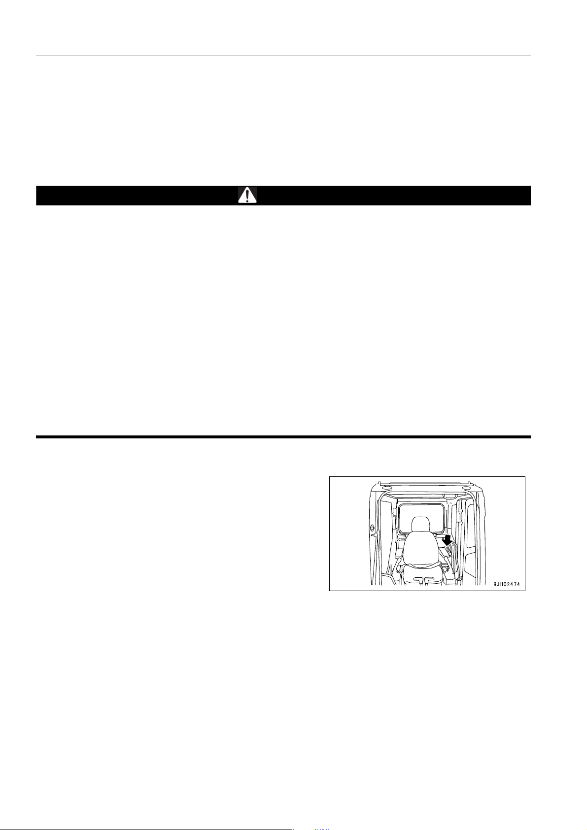
Keep this manual at the storage location for the Operation and Maintenance Manual given below so that
all personnel involved in working on the machine can consult it periodically.
In case this manual should be lost or damaged, immediat ely contact Komatsu or your Komatsu distributor
to obtain a new copy.
When you sell the machine, make sure that this manual should be provided to the new owner together
with the machine.
In this manual, measurements are expressed in internationa l standard units (SI). For the reference purpose, weight units used in the p ast are also displayed in ( ).
Storage loca tion for the Operation and Maintenance Manual:
magazine box on the left side of the operator's seat.
1-2

FOREWORD SAFETY INFORMATION
SAFETY INFORMATION 1
To enable you to use this machine safely, safety precautions and labels are given in this manual and affixed to the
machine to give explanations of situations involving potential hazards and of the methods of avoiding such situations.
Signal words
The following signal words are used to inform you that there is a potential hazardous situation that may lead to personal injury or damage.
In this manual and on machine labels, the following signal words are used to express the potential level of hazard.
DANGER
WARNING
CAUTION
Example of safety message using signal word
Indicates an imminently hazardous situation which, if not avoided, will result in death or
serious injury.
Indicates a potentially hazardous situation which, if not avoided, could result in death or
serious injury.
Indicates a potentially hazardous situation which, if not avoided, may result in minor or
moderate injury . This word is used also to alert against unsafe practices that may cause
property damage.
WARNING
When standing up from the operator's seat, always place the lock lever in the LOCK position.
If you accidentally touch the control levers when they are n ot locked, this may ca use a serious inju ry or
death.
Other signal words
In addition to the above, the following signal words are used to indicate precaution s that shou ld be followed to protect the machine or to give information that is useful to know.
NOTICE
REMARKS
This word is used for precautions that must be taken to avoid actions which could shorten
the life of the machine.
This word is used for information that is useful to know.
1-3
SAFETY INFORMATION FOREWORD
q Safety labels
Safety labels are affixed to the machine to inform the operator or maintenance worker on the spot when carrying
out operation or maintenance of the machine that may involve hazard.
This machine uses “Safety labels using words“ and “Safety labels using pictograms“ to indicate safety pr ocedur es.
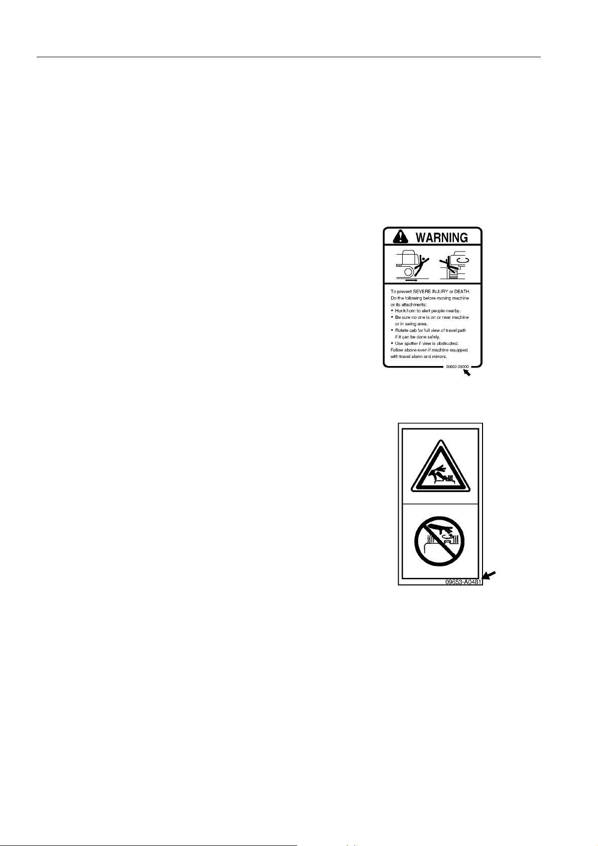
Example of safety label using words
Part No
Safety labels using pictogram
Safety pictograms use a picture to expre ss a level of hazardous condition equivalent to the signal word. These safety pictograms use pictures in order to let the operator or
maintenance worker understand the level and type of hazardous condition at all times.
Safety pictograms show the type of hazardous condition at the
top or left side, and the method of avoiding the hazardous condition at the bottom or right side. In addition, the type of hazardous condition is displayed inside a triangle and the method
of avoiding the hazardous condition is shown inside a circle.
Part No
Komatsu cannot predict every circumstance that might involve a potential hazard in operation and maintena nce.
Therefore, the safety messages in this manual and on the machine may not include all po ssible safety precautions.
If any procedures or actions not specifically recommended or allowed in this manual are used, it is your responsibility to take the necessary steps to ensure safety.
In no event should you engage in prohibited uses or actions described in this manual.
The explanations, values, and illustrations in this manual were prepared based on the latest information available
at that time. Continuing improvements in the design of this machine can lead to changes in detail which may not
be reflected in this manual. Consult Komatsu or your Komatsu distributor for the latest available information of
your machine or for questions regarding information in this manual.
The numbers in circles in the illustrations correspond to the numbers in ( ) in the text. (For example: 1 J (1))
1-4
FOREWORD SAFETY INFORMATION
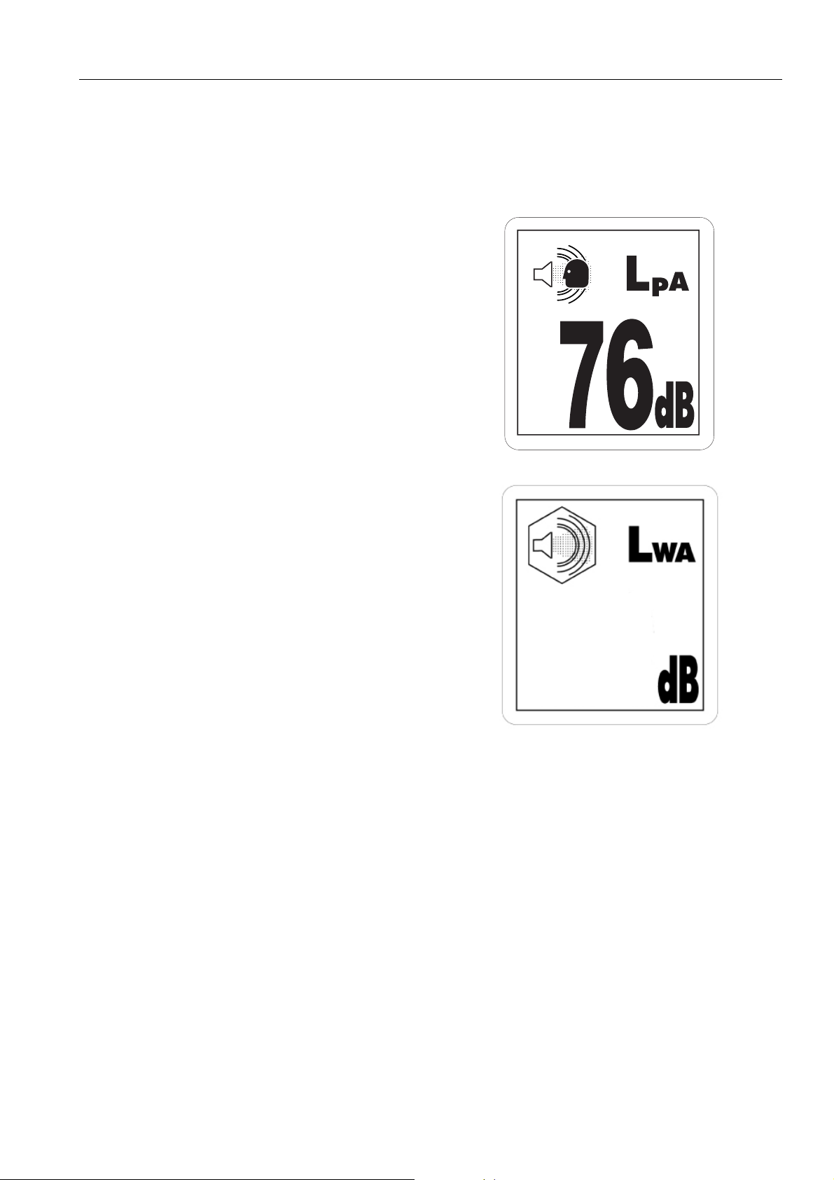
Noise emission levels 1
Two labels ind icating the machine noise level a re affixed on the
machine.
q Sound pressure level at the operator’s station, measured
according to ISO6396 (Dynamic test method, simulated
working cycle).
q Sound power level emitted by the machine, measured
according to ISO 6395 (Dynamic test method, simulated
working cycle). This is the guaranteed value as specified
in European directive 2000/14/EC.
107
1-5

SAFETY INFORMATION FOREWORD
Vibration levels 1
When used for its intended purpose, levels of vibration for the earth-moving machine transmitted from the operator’s seat are lower than or equal to the tested vibrations for the relative machinery class in compliance with ISO
7096.
The actual acceleration value for the hands and arms is less than or equal to 2.5 m/s². The actual acceleration
value for the body is less than or equal to 0.5 m/s².
These values were determined using a representative machine and measured during the typical operating condi-
tion indicated below according to the measurement procedures that are defined in the standards ISO 2631/1 and
ISO 5349.
Operating condition:
Excavating (Digging-loading-rotating-unloading-rotating)
Guide to Reduce Vibration Levels on Machine 1
The following guides can help an operator of this machine to reduce the whole body vibration levels:
1. Use the correct equipment and attachments.
2. Maintain the machine according to this manual
q Tension of crawler (for crawler machines)
q Brake and steering systems
q Controls, hydraulic system and linkages
3. Keep the terrain where the machine is working and traveling in good condition
q Remove any large rocks or obstacles
q Fill any ditches and holes
q Site manager should provide machine operators with machine and schedule time to maintain terrain con-
ditions
4. Use a seat that meets ISO 7096 and keep the seat maintained and adjusted
q Adjust the seat and suspension for the weight and size of the operator
q Wear seat belt
q Inspect and maintain the seat suspension and adjustment mechanisms
5. Steer, brake, accelerate, and move the attachment levers and pedals slowly so that the machine moves
smoothly
6. Adjust the machine speed and travel path to minimize the vibration level
q When pushing with bucket or blade, avoid sudden loading; load gradually
q Drive around obstacles and rough terrain conditions
q Slow down when it is necessary to go over rough terrain
q Make the curve radius of traveling path as large as possible
q Travel at low speed when traveling around sharp curves
1-6

FOREWORD SAFETY INFORMATION
7. Minimize vibrations for long work cycle or long distance traveling
q Reduce speed to prevent bounce
q Transport machines long distances between work sites
8. The following guidelines can be effective to minimize risks of low back pain
q Operate the machine only when you are in good he alt h.
q Provide breaks to reduce long periods of sitting in the same posture
q Do not jump down from the cab or machine
q Do not repeatedly handle and lift loads
1-7
INTRODUCTION FOREWORD
INTRODUCTION 1
This Komatsu machine is designed to be used mainly for the following work:
q Digging work
q Leveling work
q Ditching work
q Loading work
q Demolition work
See the section “RECOMMENDED APPLICATIONS (3-162)“ for further details.
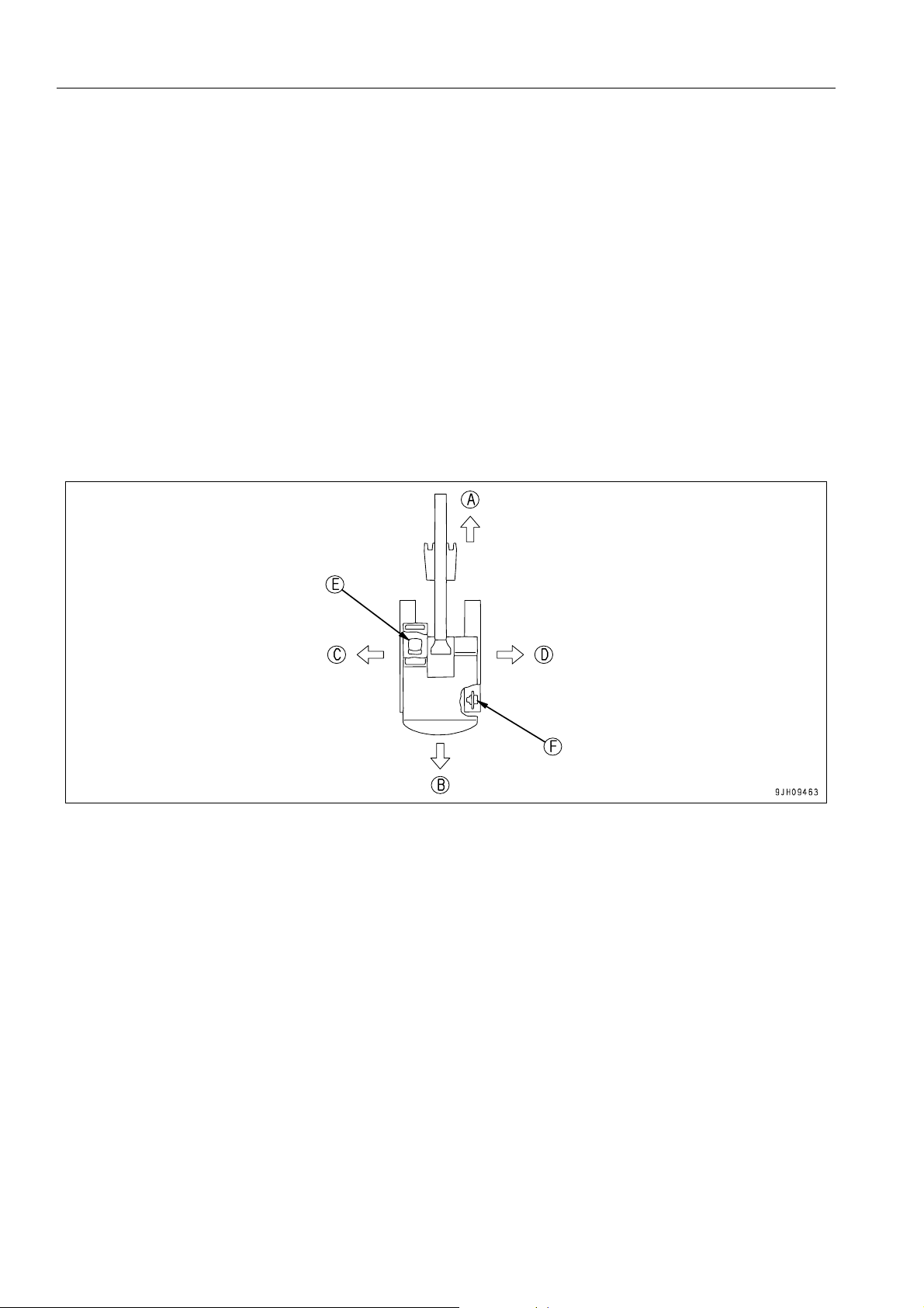
DIRECTIONS OF MACHINE 1
(A) Front (E) Operator's seat
(B) Rear (F) Sprocket
(C) Left
(D) Right
In this manual, the terms front, rear, left, and right refer to the travel direction as seen from the operator's seat
when the operator's seat is facing the front and the sprocket is at the rear of the machine.
1-8
FOREWORD INTRODUCTION
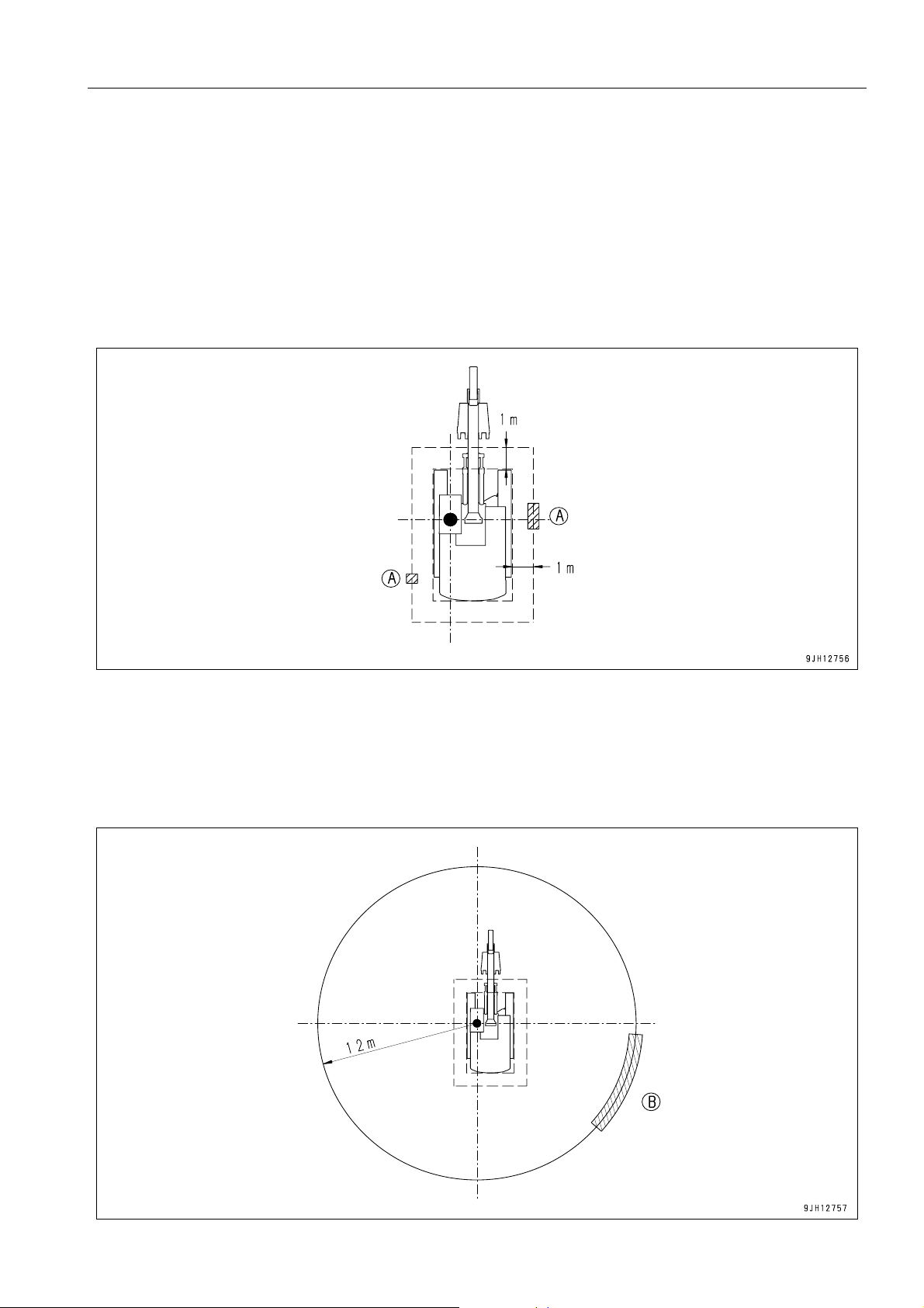
VISIBILITY FROM OPERATOR'S SEAT 1
The visibility standards (ISO 5006) for this machine require a view shown in the diagram below.
PROXIMITY VISIBILITY 1
The visibility of this machine in the area 1 m from the outside surface of the machine at a height of 1.5 m is shown
in the diagram below. The hatched area (A) shows the area where the view is blocked by part of the machine when
mirrors or other aids to visibility are installed as standard. Please be fully aware that there are places that cannot
be seen when operating the machine.
12M CIRCUMFERENCE VISIBILITY 1
The visibility at a radius of 12 m from the machine is as shown in the diagram below. The hatched areas (B) show
the areas where the view is blocked when mirrors or other aids to visibility are installed as standard. Please be
fully aware that there are places that cannot be seen when operating the machine.
1-9

INTRODUCTION FOREWORD
BREAKING-IN THE NEW MACHINE 1
NOTICE
Your Komatsu machine has been thoroughly adjusted and tested before shipment from the factory. However, ope rating the machine under full load before bre aking the machine in can adverse ly affect the perf ormance and shorten the machine life.
Be sure to break in the machine for the initial 100 hours (as indicated on the service meter).
Make sure that you fully understand the content of this manual, and pay careful attention to the following points
when breaking in the machine.
q Run the engine at idle for 15 seconds after starting it. During this time, do not operate the control levers or fuel
control dial.
q Idle the engine for 5 minutes after starting it up.
q Avoid operation with heavy loads or at high speeds.
q Immediately after starting the engine, avoid sudden starts, sudden acceleration, unnecessary sudden stops,
and sudden changes in direction.
1-10

FOREWORD PRODUCT INFORMATION
PRODUCT INFORMATION 1
When requesting service or ordering replacement parts, please inform your Komatsu distributor of the following
items.
PRODUCT IDENTIFICATION NUMBER (PIN)/MACHINE SERIAL NO. PLATE 1
On the bottom right of the operator's cab
The design of the nameplate differs according to the territory.
EPA REGULATIONS, ENGINE NUMBER PLATE 1
On the upper side of the engine cylinder head cover.
EPA: Environmental Protection Agency, U.S.A.
1-11
PRODUCT INFORMATION FOREWORD
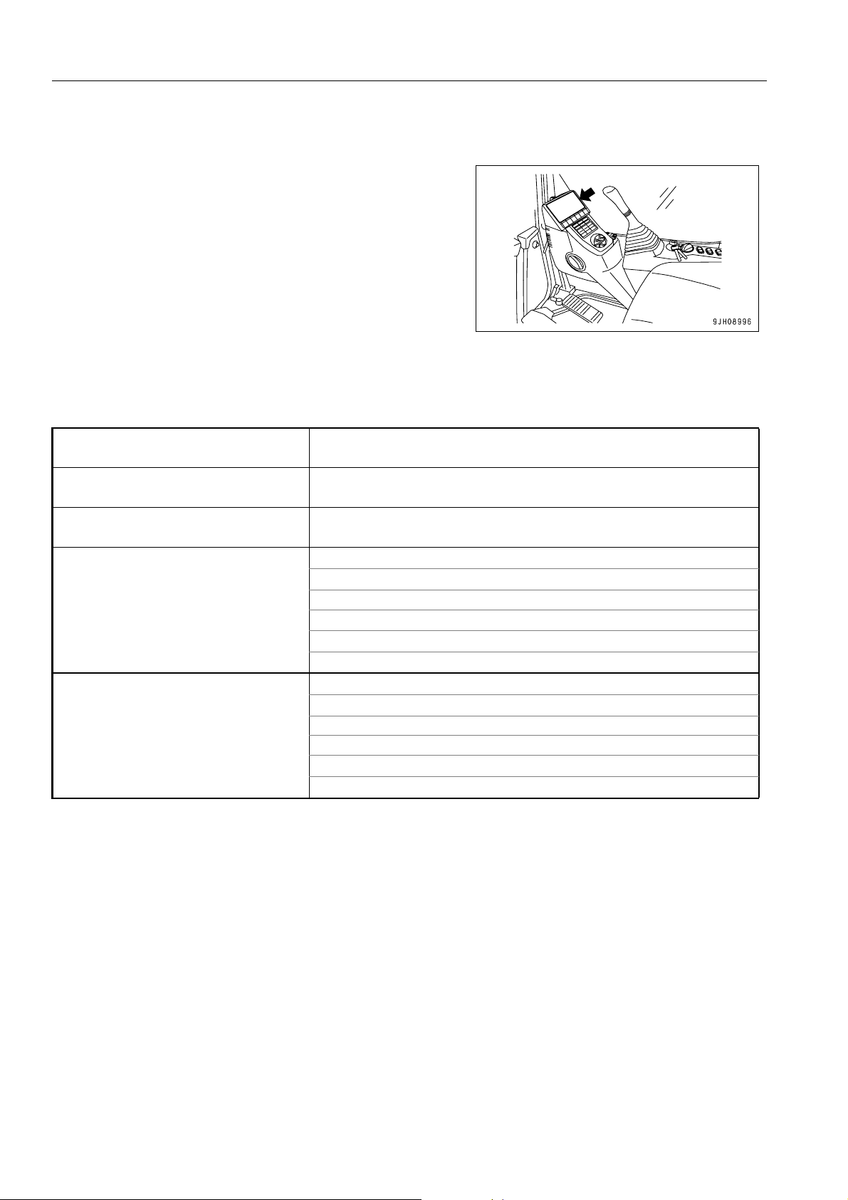
SERVICE METER LOCATION 1
On top of the machine monitor
YOUR MACHINE SERIAL NUMBERS AND DISTRIBUTOR 1
Machine serial No.
Engine serial No.
Product identification number (PIN)
Manufacturers name
Address
Distributor name
Address
Service Personnel
Phone/Fax
KOMATSU UK LTD.
Durham Road
Birtley
Chester-Le Street
County Durham DH32QX
United Kingdom
1-12
FOREWORD PRODUCT INFORMATION
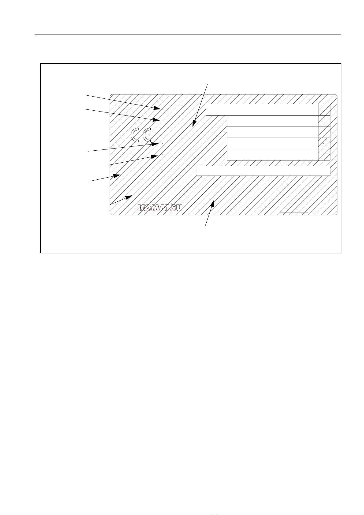
MACHINE SERIAL PLATE 1
MANUFACTURING YEAR
MODEL
SERIAL
WEIGHT
ENGINE POWER
PRODUCT
IDENTIFICATION
NUMBER
MANUFACTURER
MODEL
SERIAL No.
MANUFACT. YEAR
MASS
ENGINE POWER
Product Identification Number
MANUFACTURER
Manufactured by Komatsu UK Ltd.
for Komatsu Ltd.,Tokyo,Japan
Komatsu UK Ltd, Birtley, Co Durham, United Kingdom
kg
kW
205-00-K1291
1-13

CONTENTS
CONTENTS
FOREWORD
FOREWORD.........................................................................................................................................................1-2
SAFETY INFORMATION...................................................................................................................................... 1-3
Noise emission levels ...................................... ... ... ... ... .... ... ... ... .... ..............................................................1-5
Vibration levels............................................................................................................................................1-6
Guide to Reduce Vibration Levels on Machine..................................................................................1-6
INTRODUCTION................................................................................................................................................... 1-8
DIRECTIONS OF MACHINE ...................................................................................................................... 1-8
VISIBILITY FROM OPERATOR'S SEAT............................... .....................................................................1-9
PROXIMITY VISIBILITY ....................................................................................................................1-9
12M CIRCUMFERENCE VISIBILITY ................................................................................................ 1-9
BREAKING-IN THE NEW MACHINE ....................................................................................................... 1-10
PRODUCT INFORMATION................................................................................................................................1-11
PRODUCT IDENTIFICATION NUMBER (PIN)/MACHINE SERIAL NO. PLATE...................................... 1-11
EPA REGULATIONS, ENGINE NUMBER PLATE .......... ... ... ... .... ... ... ... .... ... ... ... ... .... ... ... ... .... ... ... ... ... .... .. 1-11
SERVICE METER LOCATION .................................................................................................................1-12
YOUR MACHINE SERIAL NUMBERS AND DISTRIBUTOR ................................................................... 1-12
MACHINE SERIAL PLATE ....................................................................................................................... 1-13
SAFETY
SAFETY INFORMATION...................................................................................................................................... 2-2
SAFETY LABELS.................................................................................................................................................2-4
LOCATION OF SAFETY LABELS..............................................................................................................2-4
SAFETY LABELS ........................ ... .... ... ... ... .... ...................................... .... ... ... ........................................... 2-5
SAFETY INFORMATION.................................................................................................................................... 2-13
SAFETY MACHINE OPERATION...................................................................................................................... 2-22
STARTING ENGINE.................................................................................................................................2-22
OPERATION.............................................................................................................................................2-24
TRANSPORTATION................................................................................................................................. 2-30
BATTERY ................................................................................................................................................. 2-31
TOWING ................................................................................................................................................... 2-33
LIFTING OBJECTS WITH BUCKET......................................................................................................... 2-34
SAFETY MAINTENANCE INFORMATION........................................................................................................2-35
1-14

CONTENTS
OPERATION
MACHINE VIEW ILLUSTRATIONS ..................................................................................................................... 3-2
OVERALL MACHINE VIEW........................................................................................................................ 3-2
CONTROLS AND GAUGES....................................................................................................................... 3-3
Machine Monitor ......................................................................................................................................... 3-4
DETAILED CONTROLS AND GAUGES.............................................................................................................. 3-5
MONITORING SYSTEM............................................................................................................................. 3-5
Basic Operation of Machine Monitor.................................................................................................. 3-6
Emergency Monitors........................................................................................................................ 3-11
Caution Monitors................................. ... ... ... ....................................... ... .... ... ... ... .... ... ... ... ................ 3-13
Basic Check Monitors...................................................................................................................... 3-16
Meter Display Portion ...................................................................................................................... 3-18
Monitor Switches Portion................................................................................................................. 3-25
Handling Function Switches ............................................................................................................ 3-33
Attachment 2 Setting ....................................................................................................................... 3-54
SWITCHES............................................................................................................................................... 3-69
CONTROL LEVERS AND PEDALS ......................................................................................................... 3-75
SUN ROOF............................................................................................................................................... 3-78
WINDSHIELD ........................................................................................................................................... 3-79
EMERGENCY ESCAPE HAMMER.......................................................................................................... 3-84
DOOR LOCK ............................................................................................................................................ 3-85
CAP WITH LOCK...................................................................................................................................... 3-85
DRINK BOX.............................................. ... ... ... ... .... ... ... ... ....................................... ... .... ......................... 3-87
MAGAZINE BOX....................................................................................................................................... 3-87
ASHTRAY................................................................................................................................................. 3-87
AIR CONDITIONER CONTROLS............................................................................................................. 3-88
Air Conditioner Control Panel.......................................................................................................... 3-88
Method of Operation........................................................................................................................ 3-92
Use Air Conditioner with Care ............... ... ... .... ... ... ... .... ... ... ... .... ... .......................................... ......... 3-98
Inspection and maintenance of Air Conditioner Equipped Machine................................................ 3-99
RADIO..................................................................................................................................................... 3-100
Control Panel......... ... ... ... .... ...................................... .... ... ... ... .... ... ... ... ... ........................................ 3-100
Controls of Radio........................................................................................................................... 3-102
Use Radio with Care...................................................................................................................... 3-104
Space for radio cassette................................................................................................................ 3-104
AUXILIARY ELECTRIC POWER.......................... .... ... ... ... .......................................... ........................... 3-105
24V Power Source......................................................................................................................... 3-105
12V Power Source......................................................................................................................... 3-105
FUSE ...................................................................................................................................................... 3-106
FUSIBLE LINK...... ... ....................................... ... ... .... ... ... ... ....................................... ... .... ....................... 3-107
CONTROLLER ....................................................................................................................................... 3-107
TOOL BOX.............................................................................................................................................. 3-108
GREASE PUMP HOLDER.............................................................................................................
FIRE EXTINGUISHER............................................................................................................................ 3-108
REFUELLING PUMP.............................................................................................................................. 3-109
ACCUMULATOR.................................................................................................................................... 3-110
......... 3-108
1-15

CONTENTS
Releasing Hydraulic Pressure With Accumulator .......................................................................... 3-110
MACHINE OPERATIONS AND CONTROLS................................................................................................... 3-111
BEFORE STARTING ENGINE ........... ... ....................................... ... ... ... .... ... ... ... ... .... .............................3-111
Walk-around Checks ..................................................................................................................... 3-111
Checks Before Starting..................................................................................................................3-112
Adjustment..................................................................................................................................... 3-119
Seat Belt .......................... ... ... .... ...................................... .... ... ... ... .... ............................................. 3-125
Operations Before Starting Engine...................................................... ... ... ... .... ... ... ... .... ... ... ... ... ....3-126
STARTING ENGINE............................................................................................................................... 3-128
AFTER STARTING ENGINE ................. .......................................... ... .......................................... .......... 3-131
Engine Warm Up .......................................... ... ... .... ... ... ... .... ... ... ....................................... ............. 3-131
Hydraulic Equipment Warm Up .....................................................................................................3-133
Operation After Completion Of Warm-Up Operation ..................................................................... 3-139
STOPPING THE ENGINE ........................ ... .... ...................................... .... ... ... ... ... .................................3-141
MACHINE OPERATION ......................................................................................................................... 3-142
Preparations for Moving the Machine............................................................................................3-142
Moving Machine Forward .............................................................................................................. 3-143
Moving Machine Backward............................................................................................................3-144
Stopping Machine..........................................................................................................................3-145
STEERING THE MACHINE....................................................................................................................3-146
Steering .........................................................................................................................................3-146
SWINGING ............................................................................................................................................. 3-148
WORK EQUIPMENT CONTROLS AND OPERATIONS ........................................................................3-149
WORKING MODE...................................................................................................................................3-151
PROHIBITED OPERATIONS .................................................................................................................3-153
GENERAL OPERATION INFORMATION ..............................................................................................3-157
TRAVELING ON SLOPES...................................................................................................................... 3-159
ESCAPE FROM MUD............................................................................................................................. 3-161
Track on One Side Stuck...............................................................................................................3-161
Tracks on Both Sides Stuck........................................................................................................... 3-161
RECOMMENDED APPLICATIONS........................................................................................................3-162
Backhoe Work ...............................................................................................................................3-162
Shovel Work ..................................................................................................................................3-162
Ditching Work ......................................... ... ... ... ... .... ...................................... .... ... ... ... .... ................3-162
Loading Work................................................ ... ... .... ... ... ... ....................................... ... .... ................3-163
BUCKET REPLACEMENT AND INVERSION........................................................................................3-164
Replacement.................................................................................................................................. 3-164
Inversion ........................................................................................................................................ 3-165
PARKING MACHINE ......... ....................................... ... .... ... ....................................... ... ... ... ....................3-166
MACHINE INSPECTION AFTER DAILY WORK....................................................................................3-168
LOCKING................................................................................................................................................3-168
TRANSPORTATION...............................................................................................................................
TRANSPORTATION PROCEDURE....................................................................................................... 3-169
LOADING AND UNLOADING WITH TRAILER ...................................................................................... 3-170
Loading.......................................................................................................................................... 3-171
Securing Machine.......................................................................................................................... 3-173
1-16
..........3-169

CONTENTS
Unloading....................................................................................................................................... 3-176
LIFTING MACHINE................................................................................................................................. 3-178
TRANSPORTATION POSTURE ............................................................................................................ 3-180
PROCEDURE FOR INCREASING OR REDUCING TRACK FRAME GAUGE...................................... 3-182
COLD WEATHER OPERATION...................................................................................................................... 3-184
COLD WEATHER OPERATION INFORMATION................................................................................... 3-184
Fuel and Lubricants...................................................... .......................................... ....................... 3-184
Cooling System Coolant................................................................................................................ 3-184
Battery ........................................................................................................................................... 3-185
AFTER DAILY WORK COMPLETION.................................................................................................... 3-186
AFTER COLD WEATHER SEASON......................................................................................................3-186
LONG TERM STORAGE.................................................................................................................................. 3-187
BEFORE STORAGE............................................................................................................................... 3-187
DURING STORAGE............................................................................................................................... 3-187
AFTER STORAGE.................................................................................................................................. 3-188
STARTING MACHINE AFTER LONG-TERM STORAGE ...................................................................... 3-188
TROUBLES AND ACTIONS ............................................................................................................................ 3-189
RUNNING OUT OF FUEL .... ... .... ... ... ... ....................................... ... .... ... ... ... ... ........................................ 3-189
PHENOMENA THAT ARE NOT FAILURES........................................................................................... 3-190
TOWING THE MACHINE ....................................................................................................................... 3-190
LIGHTWEIGHT TOWING HOLE ............................................................................................................ 3-191
SEVERE JOB CONDITION.................................................................................................................... 3-191
DISCHARGED BATTERY ...................................................................................................................... 3-192
Battery Removal and Installation................................................................................................... 3-192
Battery Charges............................................................................................................................. 3-193
Starting Engine with Booster Cables............................................... ... ... .... ... ... ... .... ... ... ... ... .... ... .... 3-194
OTHER TROUBLE ................................................................................................................................. 3-196
Electrical System........................................................................................................................... 3-196
Chassis.......................................................................................................................................... 3-197
Engine............................................................................................................................................ 3-198
Electronic Control System ............................................................................................................. 3-199
Point of Contact to Telephone when Error Occurs........................................................................ 3-200
MAINTENANCE
MAINTENANCE INFORMATION......................................................................................................................... 4-2
OUTLINE OF SERVICE........................................................................................................................................ 4-4
HANDLING OIL, FUEL, COOLANT, AND PERFORMING OIL CLINIC ............................................. ... ... .. 4-4
OIL..................................................................................................................................................... 4-4
FUEL.................................................................................................................................................. 4-5
COOLANT AND WATER FOR DILUTION ........................................................................................ 4-5
GREASE............................................................................................................................................ 4-6
CARRYING OUT KOWA (Komatsu Oil Wear Analysis) .................................................................... 4-6
STORING OIL AND FUEL................................................................................................................. 4-7
1-17

CONTENTS
FILTERS............................................................................................................................................4-7
EXPLANATION OF LUBRICATION CHART DECAL
....................................................................................................................................................................4-8
ELECTRIC SYSTEM MAINTENANCE .....................................................................................................4-10
WEAR PARTS....................................................................................................................................................4-11
WEAR PARTS LIST..................................................................................................................................4-11
RECOMMENDED FUEL, COOLANT, AND LUBRICANT .................................................................................4-12
RECOMMENDED BRANDS, RECOMMENDED QUALITY FOR PRODUCTS OTHER THAN KOMATSU
GENUINE OIL........... ... ....................................... ... ... ... .... ... ... ....................................... ... .........................4-14
TIGHTENING TORQUE SPECIFICATIONS ...................................................................................................... 4-15
TIGHTENING TORQUE LIST...................................................................................................................4-15
SAFETY CRITICAL PARTS...............................................................................................................................4-16
SAFETY CRITICAL PARTS LIST.............................................................................. ... ... ... .... ... ... ... ......... 4-16
MAINTENANCE SCHEDULE.............................................................................................................................4-17
MAINTENANCE SCHEDULE CHART......................................................................................................4-17
MAINTENANCE INTERVAL FOR HYDRAULIC BREAKER..................................................................... 4-19
MAINTENANCE PROCEDURE.......................................................................................................................... 4-20
INITIAL 1000 HOURS MAINTENANCE (ONLY AFTER THE FIRST 1000 HOURS)...............................4-20
WHEN REQUIRED................................................................................ .... ... ... ... ... .... ...............................4-21
CHECK, CLEAN AND REPLACE AIR CLEANER ELEMENT......................................................... 4-21
CLEAN INSIDE OF COOLING SYSTEM ........................................................................................ 4-27
CHECK AND TIGHTEN TRACK SHOE BOLTS..............................................................................4-30
CHECK AND ADJUST TRACK TENSION....................................................................................... 4-31
REPLACE BUCKET TEETH (VERTICAL PIN TYPE) ..................................................................... 4-33
REPLACE BUCKET TEETH (HORIZONTAL PIN TYPE)................................................................4-36
REPLACE BUCKET SIDE CUTTER, SHROUD........ ... ... .... ... ... ... .... ... ... ... ... .... ... ... ... .... ... ... ... ... .... .. 4-38
ADJUST BUCKET CLEARANCE ........... ... ... ... ... .... ... ... ... .......................................... .... ... ... ... ... ......4-39
CHECK WINDOW WASHER FLUID LEVEL, ADD FLUID..............................................................4-40
CHECK AND MAINTENANCE AIR CONDITIONER ....................................................................... 4-41
WASH WASHABLE FLOOR .. .... ...................................... .... ... ... ... .... ... ... ... ... ................................... 4-42
BLEEDING AIR FROM HYDRAULIC SYSTEM...............................................................................4-45
CHECK BEFORE STARTING ......................................................................... ......................................... 4-47
EVERY 50 HOURS MAINTENANCE........................................................................................................4-48
LUBRICATING.................................................................................................................................4-48
EVERY 250 HOURS MAINTENANCE...................................................................................................... 4-49
LUBRICATE SWING CIRCLE ...... ....................................... ... ... ... .... ... ... ....................................... .. 4-49
CHECK LEVEL OF BATTERY ELECTROLYTE ............................................................................. 4-50
CHECK FAN BELT, ALTERNATOR BELT TENSION, ADJUST..................................................... 4-52
CHECK AIR CONDITIONER COMPRESSOR BELT TENSION, ADJUST..................................... 4-53
EVERY 500 HOURS MAINTENANCE...................................................................................................... 4-54
LUBRICATING.................................................................................................................................4-54
REPLACE FUEL PRE-FILTER CARTRIDGE..................................................................................4-55
CHECK SWING PINION GREASE LEVEL, ADD GREASE............................................................4-58
CHANGE OIL IN ENGINE OIL PAN, REPLACE ENGINE OIL FILTER CARTRIDGE....................4-59
1-18

CONTENTS
CLEAN AND INSPECT RADIATOR FINS, OIL COOLER FINS, AFTERCOOLER FINS AND
CONDENSER FINS......................................................................................................................... 4-61
CLEAN AIR CONDITIONER FRESH/RECIRC FILTERS................................................................ 4-62
REPLACE BREATHER ELEMENT IN HYDRAULIC TANK ............................................ ....... ... ... ... 4-64
CHECK OIL LEVEL IN SWING MACHINERY CASE, ADD OIL...................................................... 4-65
CHECK OIL LEVEL IN FINAL DRIVE CASE, ADD OIL .................................................................. 4-66
EVERY 1000 HOURS MAINTENANCE....................................................................................................4-67
REPLACE FUEL MAIN FILTER CARTRIDGE ................................................................................ 4-67
REPLACE HYDRAULIC OIL FILTER ELEMENT............................................................................ 4-70
CHANGE OIL IN SWING MACHINERY CASE ............................................................................... 4-71
CHECK OIL LEVEL IN DAMPER CASE, ADD OIL......................................................................... 4-72
CHECK ALL TIGHTENING POINTS OF ENGINE EXHAUST PIPE CLAMPS ............................... 4-72
REPLACE HYDRAULIC TANK ADDITIONAL BREATHER ELEMENT .......................................... 4-73
CHECK NITROGEN GAS CHARGE PRESSURE IN ACCUMULATOR (for breaker) .................... 4-73
REPLACE CORROSION RESISTOR CARTRIDGE ....................................................................... 4-74
EVERY 2000 HOURS MAINTENANCE....................................................................................................4-75
CHANGE OIL IN FINAL DRIVE CASE............................................................................................ 4-75
CLEAN HYDRAULIC TANK STRAINER ......................................................................................... 4-76
CHECKING CHARGE PRESSURE OF NITROGEN GAS IN ACCUMULATOR (FOR CONTROL
CIRCUIT)......................................................................................................................................... 4-76
CHECK ALTERNATOR................................................................ ... ... ... .... ... ... ... .... ... ... ................... 4-79
CHECK ENGINE VALVE CLEARANCE, ADJUST.......................... ... ... .... ... ... ... .... ... ... ... ... .... ... ... ... 4-79
CHECK VIBRATION DAMPER ................................................. ... ... ... .......................................... ... 4-79
EVERY 4000 HOURS MAINTENANCE....................................................................................................4-80
CHECK WATER PUMP................................... ... ... ... .... .......................................... ... ...................... 4-80
CHECK STARTING MOTOR........................................................... .......................................... ... ... 4-80
REPLACE ACCUMULATOR (FOR CONTROL CIRCUIT).............................................................. 4-80
CHECK FOR LOOSENESS OF HIGH-PRESSURE PIPING CLAMP, HARDENING OF RUBBER4-81
CHECK FOR MISSING FUEL SPRAY PREVENTION CAP, HARDENING OF RUBBER.............. 4-81
EVERY 5000 HOURS MAINTENANCE....................................................................................................4-82
CHANGE OIL IN HYDRAULIC TANK.............................................................................................. 4-82
EVERY 8000 HOURS MAINTENANCE....................................................................................................4-84
REPLACE HIGH-PRESSURE PIPING CLAMP .............................................................................. 4-84
REPLACE FUEL SPRAY PREVENTION CAP................................................................................ 4-84
SPECIFICATIONS
SPECIFICATIONS................................................................................................................................................ 5-2
ATTACHMENTS ANDD OPTIONS
GENERAL PRECAUTIONS FOR SAFETY.......................................................................................................... 6-2
PRECAUTIONS WHEN SELECTING....................... ... ... .......................................... ... .... ... ... ... .................. 6-2
READ THE INSTRUCTION MANUAL THOROUGHLY.............................................................................. 6-2
PRECAUTIONS WHEN REMOVING OR INSTALLING............................................................................. 6-2
PRECAUTIONS WHEN USING................... ... ... ... .... ... ... ... .... ... ... ... .......................................... .................. 6-3
1-19

CONTENTS
HYDRAULIC QUICK COUPLER PIPING.............................................................................................................6-4
LOCATIONS...................................................................................................................................... 6-4
OPERATION......................................................................................................................................6-5
BUCKET WITH HOOK ......................................................................................................................................... 6-7
HOOK CONDITION .................................................................................................................................... 6-7
PROHIBITED OPERATIONS .....................................................................................................................6-7
MACHINE READY FOR ATTACHMENT ............................................................................................................. 6-8
LOCATIONS ............................................................................................................................................... 6-8
HYDRAULIC CIRCUIT..............................................................................................................................6-12
Switching Hydraulic Circuit ........................... ................................................................................... 6-12
Adjusting Oil Flow............................................................................................................................ 6-12
Switching Between Breaker and General Attachment...................... ... ... ... ... .... ... ... ... .... ... ...............6-12
Hydraulic Circuit Connection ........................................................................................................... 6-13
Oil Flow Path ...................................................................................................................................6-14
Replace Additional Breaker Filter Element......................................................................................6-15
ATTACHMENT REMOVAL AND INSTALLATION.................................................................................... 6-17
Attachment Removal ....................................................................................................................... 6-17
Attachment Installation ................................. ... ... .... ... ... ... ....................................... ... .... ... ...............6-19
ATTACHMENT OPERATIONS................................................................................................................. 6-21
Operation When Using Breaker.......................................................................................................6-21
Operation When Using General Attachment 1 (e.g. Crusher). ........................................................6-23
Working Mode Selection.................................................. .... ... ... ... .... ... ... ... ... ................................... 6-24
Operation When Using Attachment 2 (e.g clamshell rotation, crusher rotation)..............................6-25
LONG TERM STORAGE.......................................................................................................................... 6-25
SPECIFICATIONS....................................................................................................................................6-25
ATTACHMENT GUIDE.......................................................................................................................................6-26
ATTACHMENT COMBINATIONS............................................................................................................. 6-26
SELECTION OF TRACK SHOES.............................................................................................................6-28
METHOD OF SELECTING SHOES ................................................................................................6-28
RECOMMENDED ATTACHMENT OPERATIONS............................................................................................. 6-29
HYDRAULIC BREAKER...........................................................................................................................6-29
HANDLING MACHINES EQUIPPED WITH KOMTRAX....................................................................................6-33
BASIC PRECAUTIONS ............ ... ... .... ... ... ... .... ... ... ....................................... ... ... ... .... ... ... ... .... ... ...............6-33
SUPER LONG FRONT BOOM AND ARM.........................................................................................................6-34
OPERATION INSTRUCTION ................................................................................................................... 6-34
WORKING MODES .................................................................................................................................. 6-35
CHECKS BEFORE STARTING....................................................................................................... 6-36
USING SUPER LONG FRONT .......................................................................................................6-36
METHOD OF WORK................................................. ... ... ....................................... ... .... ... ... ... ......... 6-38
WHEN TRAVELLING ...................................................................................................................... 6-38
CONTROL LEVERS, PEDALS........................................................................................................6
-39
TRANSPORT & STORAGE OF SUPER LONG FRONT MACHINE ........................................................6-42
INSTALLATION OF SUPPORTING LINK ....................................................................................... 6-42
1-20

CONTENTS
TRANSPORTATION OF SUPER LONG FRONT MACHINE.......................................................... 6-43
WORKING RANGE OF SUPER LONG FRONT....................................................................................... 6-44
LIFTING CAPACITY PC450 LC 20m SUPER LONG FRONT ........................................................ 6-45
MAINTENANCE........................................................................................................................................ 6-46
SPECIAL SERVICE REQUIREMENTS FOR SUPER LONG FRONT WORK EQUIPMENT.......... 6-46
EVERY 50 HOURS SERVICE......................................................................................................... 6-47
EVERY 100 HOURS SERVICE...................................................................................................... 6-48
HIGH REACH DEMOLITION EQUIPMENT 27M
GENERAL VIEW OF MACHINE........................................................................................................................... 7-2
CAUTION ITEMS............................................................................................................................... 7-3
POSITION FOR ATTACHING SAFETY LABELS................................................................................................ 7-4
POSITION FOR ATTACHING SAFETY LABELS....................................................................................... 7-4
SAFETY LABELS ....................................................................................................................................... 7-5
CONTROL LEVERS AND SWITCHES ................................................................................................................ 7-6
SAFETY LOCK LEVER .............................................................................................................................. 7-6
TRAVEL LEVERS....................................................................................................................................... 7-7
WORK EQUIPMENT CONTROL LEVERS................................................................................................. 7-8
ATTACHMENT ROTATION (with auto-deceleration)................................................................................. 7-9
INTERMEDIATE LINK CONTROL PEDAL (with auto-deceleration) ........................................................ 7-10
CRUSHER CONTROL FOR OPENING AND CLOSING.......................................................................... 7-11
TILTING CAB MECHANISM OPERATION............................................................................................... 7-12
BOOM ANGLE ALARM BUZZER CANCEL SWITCH.................................... .... ... ... ... .... ... ... ... ... .... ... ... ... 7-13
CEILING WINDOW WIPER SWITCH....................................................................................................... 7-14
MACHINE OPERATIONS AND CONTROLS..................................................................................................... 7-15
BEFORE STARTING ENGINE ................................................................................................................. 7-15
FUNCTION CHECK.................................................................................................................................. 7-16
PRECAUTIONS WHEN OPERATING......................... ... .......................................... ... .............................7-16
PROHIBITON OF WORK OUTSIDE SPECIFIED WORKING RANGE.................................................... 7-17
PROHIBITION OF WORK AT THE STROKE END OF A CYLINDER...................................................... 7-20
PROHIBITION OF WORK WITH HYDRAULIC BREAKER ...................................................................... 7-21
WHEN WORKING IN MEDIUM REACH CONFIGURATION ................................................................... 7-21
OPERATION....................................................................................................................................................... 7-22
ADJUSTMENT OF HYDRAULIC VARIABLE GAUGE UNDERCARRIAGE, (Where Fitted).................... 7-22
OPERATING WORK EQUIPMENT .......................... ... ... ... .... ... ... ... .... ...................................... ... .... ... ...... 7-23
ATTACHMENT CONTROL................................ ... .......................................... .......................................... 7-24
RAISING WORK EQUIPMENT................................................................................................................. 7-25
WORKING RANGE AND USING RANGE OF BOOM.............................................................................. 7-27
POSTURE WHEN LEAVING MACHINE .................................................................................................. 7-30
DEMOLITION DIGGING BOOM INSTALLATION AND REMOVAL.................................................................. 7-31
PROCEDURE FOR INSTALLATION AND REMOVAL OF DEMOLITION DIGGING EQUIPMENT........ 7-31
REMOVAL OF HIGH REACH WORK EQUIPMENT....................................................................... 7-31
1-21

CONTENTS
FITTING DEMOLITION DIGGING EQUIPMENT.......... ... .... ... ... ... .... ... ... ... ... .... ... ... ... .... ... ... ... ... .... .. 7-35
REMOVAL OF DEMOLITION DIGGING EQUIPMENT...................................................................7-39
CONNECTING DIGGING ARM TO DEMOLITION DIGGING BOOM............................................. 7-39
MEDIUM REACH.............................................................................................................................7-40
PURGING AIR PROCEDURES.......................................................................................................................... 7-41
PURGING PROCEDURE TO REMOVE AIR FROM HYDRAULIC CYLINDER LINES............................ 7-41
PROCEDURE FOR PURGING AIR FROM BOOM LOCK VALVE PPC CIRCUIT................................... 7-41
PURGING AIR FROM HYDRAULIC DRIFT PREVENTATIVE VALVE PPC CIRCUITS OF MID LINK AND
ARM CYLINDER....................................................................................................................................... 7-43
TRANSPORTATION
(high reach demolition equipment fitted) .......................................................................................................7-45
PROCEDURE FOR LOADING ON TO TRAILER..................................................................................... 7-45
TRANSPORTATION (demolition digging equipment fitted)......................................................................7-46
PROCEDURE FOR LOADING ON TO TRAILER............................................................................ 7-46
TRANSPORTATION (high reach demolition equipment alone)................................................................ 7-46
PROCEDURE FOR LOADING ON TO TRAILER............................................................................ 7-46
SPECIFICATIONS.............................................................................................................................................. 7-51
WORKING RANGE (PC450LCD HIGH REACH) .....................................................................................7-51
WORKING RANGE (PC450LCD MEDIUM REACH)................................................................................ 7-52
WORKING RANGE (PC450LCD LOW REACH) ......................................................................................7-53
WORKING RANGE (PC450LCD DIGGING) ............................................................................................7-54
WEIGHTS AND DIMENSIONS.................................................................................................................7-55
TRANSPORTATION (High and Medium Reach work equipment) - PC450LCD ......................................7-56
TRANSPORTATION (Digging equipment) - PC450LCD.......................................................................... 7-57
EXPLANATION OF LIFTING CAPACITY CHART....................................................................................7-58
INDEX
COLOPHON
1-22

SAFETY
12
WARNING
Please read and make sure that you fully understand the
precautions described in this manual and the safety labels
on the machine. When operating or servicing the machine,
always follow these precautions strictly.

SAFETY INFORMATION SAFETY
SAFETY INFORMATION 2
SAFETY LABELS................................................................................................................................................ 2-42
LOCATION OF SAFETY LABELS............................ ... ... .... ... ... ... .... ... ... ... ....................................... ............ 2-42
SAFETY LABELS.........................................................................................................................................2-52
SAFETY INFORMATION
Safety rules................................................................................................................................................ 2-132
If problems are found.................................................................................................................................2-132
Working wear and personal protective items.............................................................................................2-132
Fire extinguisher and first aid kit ................................................................................................................ 2-132
Safety equipment.......................................................................................................................................2-142
Keep machine clean...................................................................................................................................2-142
Keep operator's compartment clean ..........................................................................................................2-142
Leaving operator's seat with lock............................................................................................................... 2-142
Handrails and steps .................. ... ... ... .... ... .......................................... .......................................................2-152
Precautions when working in high place.................................................................................................... 2-152
Mounting and dismounting.........................................................................................................................2-152
No persons on attachments.......................................................................................................................2-152
Do not get caught in articulated portion ........................................................................ ... ... ... ....................2-152
Burn prevention..........................................................................................................................................2-162
Fire prevention and explosion prevention..................................................................................................2-162
Action if fire occurs.....................................................................................................................................2-172
Windshield washer fluid ............... ... ... .... ... ... ... .... ... ... ... ... .... ... .......................................... ..........................2-172
Falling objects, flying objects and intruding objects prevention ................................................................. 2-182
Attachment installation.... ... .......................................... .......................................... .................................... 2-182
Attachment combinations.................................... ... ... ... ... .......................................... ................................. 2-182
Cab window glasses .................... ... ... .... ... ... ... .......................................... .................................................2-182
Unauthorized modifications ........................................................................................................................ 2-192
Safety at jobsite.......................................................................................................................................... 2-192
Working on loose ground........................................................................................................................... 2-19
Distance to high voltage cables .................................................................................................................2-202
Ensure good visibility .................................................................................................................................2-202
Ventilation for enclosed area......................................................................................................................2-212
Signalman's signal and signs.............................. .......................................... ... ... ... ... ................................. 2-212
Emergency exit from operator's cab .......................................................................................................... 2-212
Asbestos dust hazard prevention............................................................................................................... 2-212
2
SAFETY MACHINE OPERATION .................................................................................................................... 2-222
STARTING ENGINE..................................................................................................................................2-222
Checks before starting engine ............................................................................................................2-222
Safety rules for starting engine ...........................................................................................................2-232
Starting engine in cold weather...........................................................................................................2-232
OPERATION.............................................................................................................................................. 2-242
Checks before operation.....................................................................................................................2-242
Safety rules for changing machine directions ..................................................................................... 2-242
Safety rules for traveling .....................................................................................................................2-252
Traveling on slopes............................................................................................................................. 2-252
Operations on slopes................................................................ ... ... ... .... ... .......................................... 2-262
Prohibited operations.......................................................................................................................... 2-272
Operations on snow..................................................................... ... ... .... ... .......................................... 2-282
Parking machine................................... ... .... ... ... ... ... .... ... ... ....................................... ... .......................2-292
TRANSPORTATION..................................................................................................................................2-302
Loading and unloading........................................................................................................................2-302
Shipping the machine .........................................................................................................................2-302
BATTERY................................................................................................................................................... 2-312
2-2

SAFETY SAFETY INFORMATION
Battery hazard prevention................................................................................................................... 2-312
Starting engine with booster cables.................................................................................................... 2-322
TOWING ....................................................................................................................................................2-332
Safety rules for towing ........................................................................................................................ 2-332
LIFTING OBJECTS WITH BUCKET.......................................................................................................... 2-342
Safety rules for lifting objects..............................................................................................................2-342
SAFETY MAINTENANCE INFORMATION....................................................................................................... 2-352
Warning Tag .............................................................................................................................................. 2-352
Keep Work Place Clean and Tidy... ... ... ... .... ... ... ... .......................................... ... .... ... ... ... ........................... 2-352
Appoint Leader when Working with Others.................. ... ... ... .... ... ... ... .... ... ................................................. 2-352
Stop Engine Before Carrying Out Maintenance.........................................................................................2-362
Two Workers for Maintenance when Engine is Running ........................................................................... 2-36 2
Proper Tools ......... ....................................... ... ... ... ... .... ... ....................................... ... ... .............................. 2-372
Accumulator, Gas spring............................................................................................................................ 2-372
Personnel...................................................................................................................................................2-372
Attachments............................................................................................................................................... 2-382
Work Under the Machine ........................................................................................................................... 2-382
Noise.......................................................................................................................................................... 2-382
When Using Hammer................................................................................................................................. 2-382
Welding Works............................ .... ... ... ... .... ...................................... .... ... ... ... ... ........................................ 2-382
Removing Battery Terminals................. ... .... ... ... ... .......................................... ........................................... 2-392
Safety First when Using High-pressure Grease to Adjust Track Tension.................................................. 2-392
Do Not Disassemble Recoil Springs.......................................................................................................... 2-392
Safety Rules for High-pressure Oil ............................................................................................................ 2-392
Precaution for High Fuel Pressure............................... ... ... ... .... ... ... ... .... ... ... ..............................................2-402
Safety Handling High-pressure Hoses....................................................................................................... 2-402
Precaution for High Voltage................................................................... .................................................... 2-402
Waste Materials ......................................................................................................................................... 2-412
Air Conditioner Maintenance...................................................................................................................... 2-412
Compressed Air......................................................................................................................................... 2-412
Periodic Replacement of Safety Critical Parts ................................................................................
........... 2-412
2-3
SAFETY LABELS SAFETY
SAFETY LABELS 2
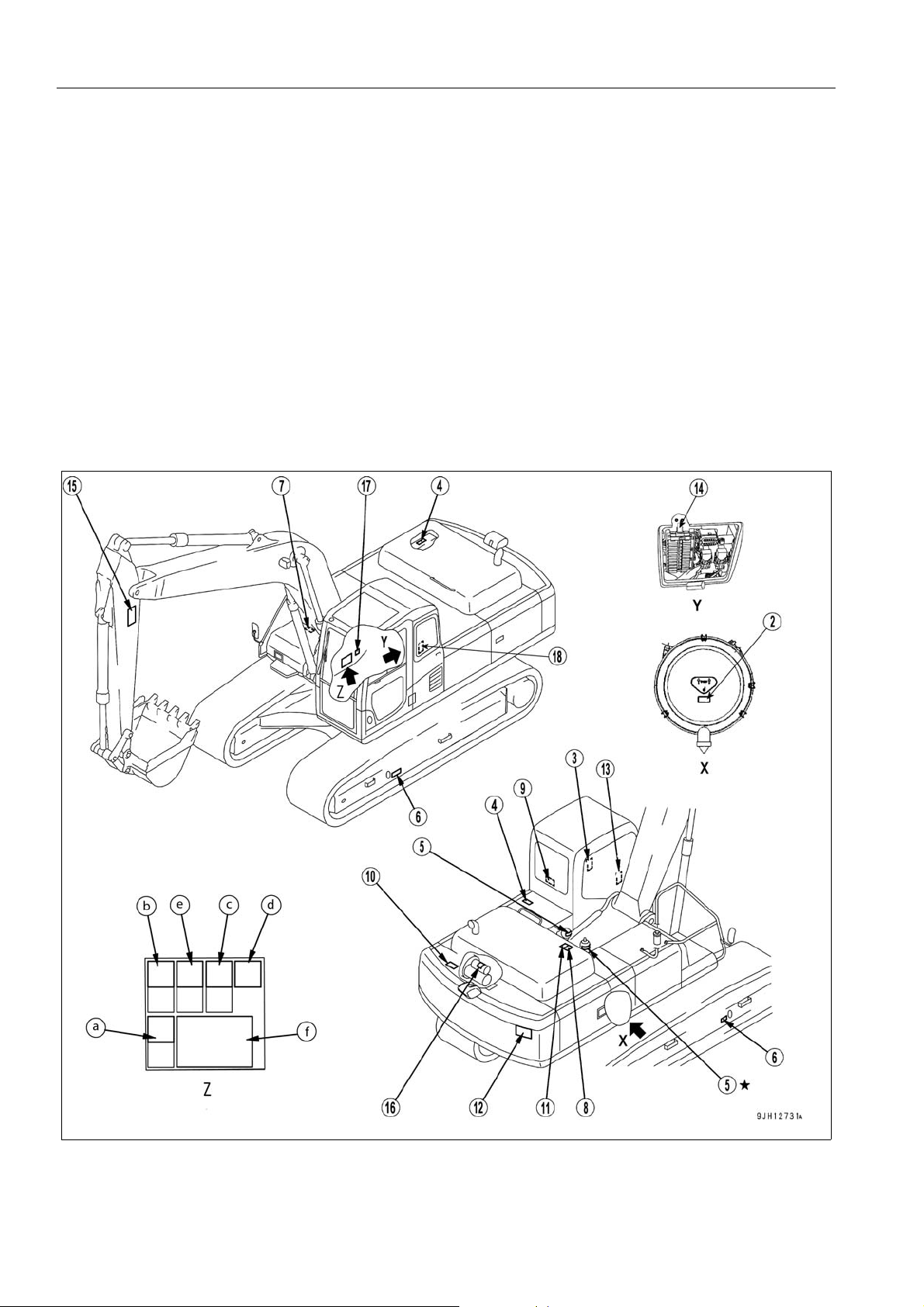
The following warning signs and safety labels are used on this machine.
q Be sure that you fully understand the correct position and content of labels.
q To ensure that the content of labels can be read properly, be sure that they are in the correct place and always
keep them clean. When cleaning them, do not use organic solvents or gasoline. These may cause the labels to
peel off.
q There are also other labels in addition to the warning signs and safety labels. Handle those labels in the same
way.
q If the labels are damaged, lost, or cannot be read properly, replace them with new ones. For details of the part
numbers for the labels, see this manual or the actual label, and place an order with Komatsu distributor.
LOCATION OF SAFETY LABELS 2
a: if equipped
2-4
SAFETY SAFETY LABELS
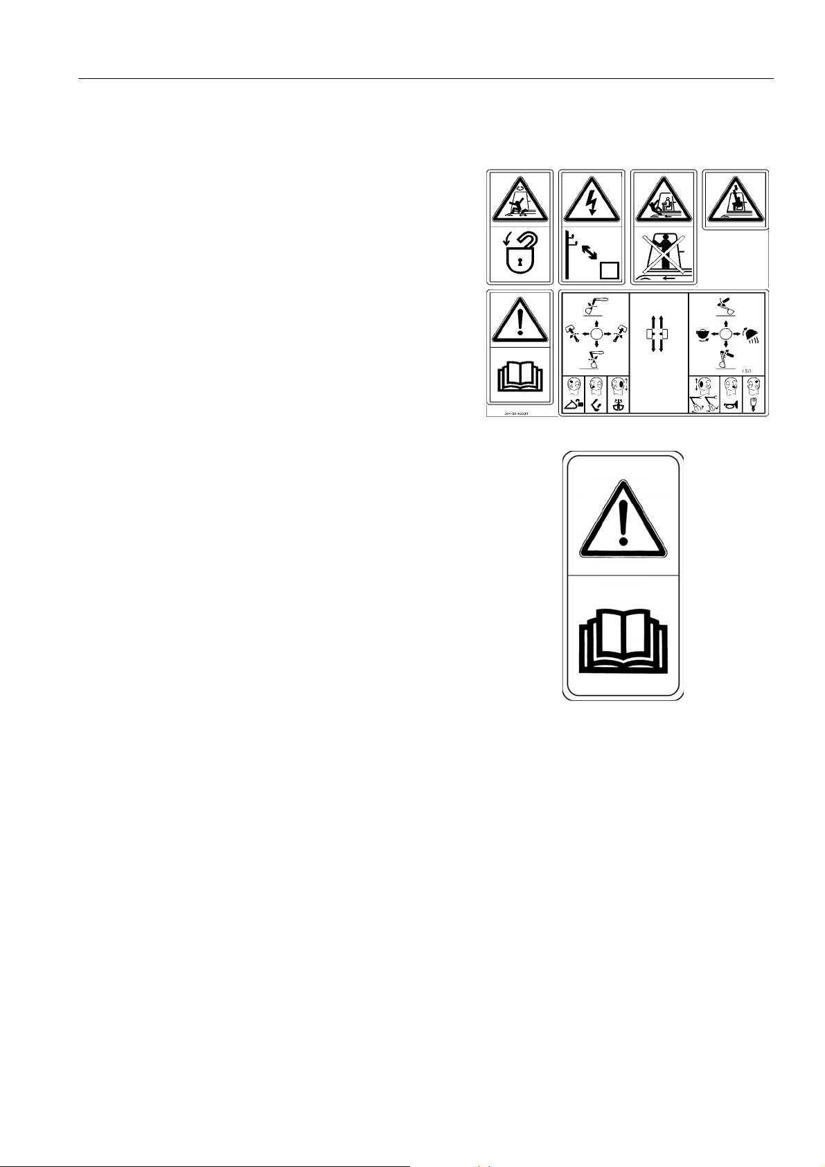
SAFETY LABELS
1. (20Y-00-K2020)
q Warnings for operation , inspection and maintenance
q Improper operation and maintenance can cause serious
injury or death.
q Read the manual and labels before operation and mainte-
nance.
Follow instructions and warnings in manual and in labels on
machine.
q Warning!
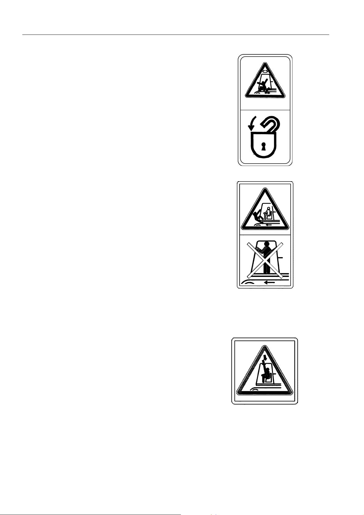
q a. Read the manual before operating, maintenance, disas-
sembly, assembly and transportation.
2-5
SAFETY LABELS SAFETY
q b. Always apply lock when leaving operator’s seat.
q c. WARNING - No passengers
No passengers allowed to ride on machine while it is moving
q d. WARNING - DANGER OF FALLING OBJECTS
Do not operate where a danger of falling objects exists.
Consult your dealer for fitting of FOPS protection
.
2-6

SAFETY SAFETY LABELS
q e. Caution for going close to electric cables.
q An electrocution hazard if the machine is brought too near to
electric power lines
q Keep a safe distance from electric power lines.
q f. Control levers operational function diagram.
WARNING
In order to prevent an accident resulting in injury or death
caused by error-operation, confirm the machine motion
and indicated operating pattern, when operating
machines. Pay attention to the circumference and operate
slowly when confirming the machine motion.
(2) Caution for operation, inspection and mainte nance
(20E-00-K1120.)
q Read the manual before operation, maintenance, disassem-
bly, assembly and transportation.
2-7

SAFETY LABELS SAFETY
(3) Caution when stowing front window (09803-A0481)
q Sign indicates a hazard from falling window.
q After raising window , be sure to lock it in place with lock pins.
(4) Caution for high-temperature coolant and hydraulic oil
(09653-A0481)
q Never remove the cap when the engine is at operating (high)
temperature. Steam or high temperature oil blowing up from
the radiator or hydraulic tank, will cause personal injury and/
or burns.
q Never remove the radiator cap or hydraulic tank oil filler
when cooling water or hydraulic oil is at high temperature.
(5) Caution for handling accumulator.
(09659-A057B)
q There is the hazard of explosion causing injury.
q Do not disassemble the accumulator, make holes in it, weld
it cut it, hit it, roll it or bring it near flame.
(6) Caution when adjusting track tension (09657-A0881)
q Sign indicates a hazard of flying plug from track adjuster that
could cause injury.
q Read manual and adjusting track for safe and proper han-
dling.
2-8

SAFETY SAFETY LABELS
(7) Caution for handling cable (09808-A0881)
q Sign indicates an electric hazard from handling the cable.
q Read manual for safe and proper handling.
(8) Stop rotating parts when inspection and maintenance
(09667-A0481)
q Sign indicates a hazard of rotating parts, such as belt.
q Turn off before inspection and maintenance.
(9) Emergency escape (09844-00050)
2-9

SAFETY LABELS SAFETY
(10) Caution against falling (09805-A0881)
q There is the hazard of falling down.
q Do not go close to the edge of the machine by mistake.
(11) Caution against falling (09805-C0481)
q Sign indicates a hazard of falling.
q Do not step here!.
(12) Prohibited to enter within swing range (20E-00-K1150)
q There is danger of getting caught when upper structure
swings.
q Do not enter range of swing.
2-10

SAFETY SAFETY LABELS
(13) Caution for use of hydraulic quick coupler piping system
(20J-00-11271)
q There is a danger of an exposed person being killed by fall-
ing attachment.
q Read the manual for safe operation.
14) (206-00-K1010)
q Pump Control override switch and swing lock override switch
q Read the operation manual before operation
(15) Keeping out of working range area (20E-00-K1140)
q Sign indicates a hazard of being hit by the wor king de vice of
the machine.
q Keep away from the machine during operation.
2-11

SAFETY LABELS SAFETY
(16) Prohibition of jump start (09842-A0481)
q Star t the engine only af ter sitting down in the oper ator’s seat.
q Do not attempt to start the engine by short-circuiting the
engine starting circuit. Such an act may cause a serious
bodily injury or fire.
(17) Caution when swinging or traveling in reverse
WARNING
When swinging or backing up excavator, press button to
change display mode on monitor so you can se e rear and
side of machine.
Before moving, look around and at mirror and monitor to
confirm that no one is around the machine. Failure to do
so can result in serious injury or death.
(18) Overload caution (208-00-76910).
q Do not exceed the safe lifting loads.
2-12

SAFETY SAFETY INFORMATION
SAFETY INFORMATION 2
SAFETY RULES
q Only trained and authorized personnel can operate and maintain the machine.
q Follow all safety rules, precautions and instructions when operating or performing maintenance on the machin e.
q If you are under the influence of alcohol or medication, your ability to safely operate or repair your machine may
be severely impaired putting yourself and everyone else on your jo b site in danger.
q When working with another operator or with a person on work site traffic duty, be sure that all personnel under-
stand all hand signals that are to be used.
IF PROBLEMS ARE FOUND
If you find any problems in the machine during operation o r mainten ance (noise, vibration, smell, in correct gauges,
smoke, oil leakage, etc., or any abnormal display on the warning devices or monitor), report to the person in
charge and have the necessary action taken. Do not operate the machine until the problem has been corrected.
WORKING WEAR AND PERSONAL PROTECTIVE ITEMS
q Do not wear loose clothing and accessories. There is a hazard that they may catch on control levers or other
protruding parts.
q If you have long hair and it hangs out from your hard hat, there is a hazard that it may get caught up in the
machine, so tie your hair up and be careful not to let it get caught.
q Always wear a hard hat and safety shoes. If the nature of
the work requires it, wear safety glasses, mask, gloves, ear
plugs, and safety belt when operating or maintaining the
machine.
q Check that all protective equipment functions properly
before using it.
FIRE EXTINGUISHER AND FIRST AID KIT
Always follow the precautions below to prepare for action if any injury or fire should occur.
q Be sure that fire extinguishers have been provided and read
the labels to ensure that you know how to use them in emergencies.
q Carry out periodic inspection and maintenance to ensure
that the fire extinguisher can always be used.
q Provide a first aid kit in the storage point. Carry out periodic
checks and add to the contents if necessary.
2-13

SAFETY INFORMATION SAFETY
SAFETY EQUIPMENT
q Be sure that all guards and covers are in their proper position. Have guards and covers repaired immediately if
they are damaged.
q Understand the method of use of safety features and use them properly.
q Never remove any safety features. Always keep them in good operating condition.
KEEP MACHINE CLEAN
q If water gets into the electrical system, there is a hazard that
it will cause malfunctions or incorrect operation. Do not use
water or steam to wash the electrical system (sensors, connectors).
q If inspection and maintenance is carried out when the
machine is still dirty with mud or oil, there is a hazard that
you will slip and fall, or that dirt or mud will get into your
eyes. Always keep the machine clean.
KEEP OPERATOR'S COMPARTMENT CLEAN
q When entering the operator's compartment, always remove all mud and oil from the soles of your shoes.
If you operate the pedal with mud or oil affixed to your shoes, your foot may slip and this may cause a serious
accident.
q Do not leave parts or tools lying around the operator's compartment.
q Do not stick suction pads to the window glass. Suction pads act as a lens and may cause fire.
q Do not use cellular telephones inside the operator's compartment when driving or operating the machine.
q Never bring any dangerous objects such as flammable or explosive items into the operator's compartment.
LEAVING OPERATOR'S SEAT WITH LOCK
q Before standing up from the operator's seat (such as when
opening or closing the front window or roof window, or when
removing or installing the bottom window, or when adjusting
the operator's seat), always lower the work equipment completely to the ground, set lock lever (1) securely to the LOCK
position (L), then stop the engine. If you accidentally touch
the control levers or control pedals when they are not
locked, there is a hazard that the machine may suddenly
move and cause serious injury or property da m ag e .
q When leaving the machine, always lower the work equip-
ment completely to the ground, set lock lever (1) securely to
the LOCK position (L), then stop the engine. Use the key to
lock all the equipment. Always remove the key, take it with
you, and keep it in the specified place.
2-14

SAFETY SAFETY INFORMATION
HANDRAILS AND STEPS
To prevent personal injury caused by slipping or falling off the machine, always do as follows.
q Use the handrails and steps marked by arrows in the dia-
gram on the right when getting on or off the machine.
q To ensure safety, always face the machine and maintain
three-point contact (both feet and one hand, or both hands
and one foot) with the handrails and steps (including the
track shoe) to ensure that you support yourself.
q Do not grip the control levers or lock lever when getting on or
off the machine.
q Never climb on the engine hood or covers where there are
no non-slip pads.
q Before getting on or off the machine, check the handrails
and steps (including the track shoe). If there is any oil,
grease, or mud on the handrails or steps (including the track
shoe), wipe it off immediately. Always keep these parts
clean. Repair any damage and tighten any loose bolts.
q Do not get on or off the machine while holding tools in your hand.
PRECAUTIONS WHEN WORKING IN HIGH PLACES
When working at high places, use a step ladder or other stand to ensure that the work can be carried out safely.
MOUNTING AND DISMOUNTING
q Never jump on or off the machine. Never get on or off a moving machine.
q If the machine starts to move when there is no operator on the machine, do not jump on to the machine and try
to stop it.
NO PERSONS ON ATTACHMENTS
Never let anyone ride on the work equipment, or other att achments. There is a hazard of falling and suffering serious injury.
DO NOT GET CAUGHT IN ARTICULATED PORTION
The clearance around the work equipment will change according to the movement of the link. If you get caught,
this may lead to serious personal injury. Do not allow anyone to approach any rotating or telescoping part.
2-15

SAFETY INFORMATION SAFETY
BURN PREVENTION
Hot coolant
q To prevent burns fro m hot water or steam spu rting out wh en
checking or draining the coolant, wait for the water to cool to
a temperature where it is possible to touch the radiator cap
by hand before starting the operation. Even when the coolant has cooled down, loosen the cap slowly to relieve the
pressure inside the radiator before removing the cap.
Hot oil
q To prevent burns from hot oil spurting out when checking or
draining the oil, wait for the oil to cool to a temperature
where it is possible to touch the cap or plug by hand before
starting the operation. Even when the oil has cooled down,
loosen the cap or plug slowly to relieve the internal pressure
before removing the cap or plug.
FIRE PREVENTION AND EXPLOSION PREVENTION
q Fire caused by fuel or oil
Fuel, oil, antifreeze, and window washer liquid are particularly flammable and can be hazardous. To prevent fire,
always observe the following:
q Do not smoke or use any flame near fuel or oil.
q Stop the engine before refueling.
q Do not leave the machine while adding fuel or oil.
q Tighten all fuel and oil caps securely.
q Do not spill fuel on overheated surfaces or on parts of
the electrical system.
q Use well-ventilated areas for adding or storing oil and
fuel.
q Keep oil and fuel in the determined place and do not
allow unauthorized persons to enter.
q After adding fuel or oil, wipe up any spilled fuel or oil.
q When carrying out grinding or welding work on the
chassis, move any flammable materials to a safe plac e
before starting.
q When washing parts with oil, use a non-flammable oil.
Diesel oil and gasoline may catch fire, so do not use
them.
q Put greasy rags and other flammable materials into a
safe container to maintain safety at the work place.
q Do not weld or use a cutting torch to cut any pipes or
tubes that contain flammable liquids.
2-16

SAFETY SAFETY INFORMATION
q Fire caused by accumulation of flammable material.
Remove any dry leaves, chips, pieces of paper, dust, or any other flammable materials accumulated or affixed
around the engine, exhaust manifold, muffler, or battery, or inside the undercovers.
q Fire coming from electric wiring
Short circuits in the electrical system can cause fire.
q Always keep ele ctric wiring connections clean and securely tightened.
q Check the wiring every day for looseness or damage. Tighten any loose connectors or wiring clamps.
Repair or replace any damaged wiring.
q Fire coming from hydraulic line
Check that all the hose and tube clamps, guards, and cushions are securely fixed in position.
If they are loose, they may vibrate during operation and rub against other parts. This may lead to damage to
the hoses, and cause high-pressure oil to spurt out, leading to fire damage or serious injury.
q Explosion caused by lighting equipment
When checking fuel, oil, battery electrolyte, window washer fluid, or coolant, always use lighting with anti
explosion specifications. If such lighting equipment is not used, ther e is danger of explosion that ma y cause
serious injury.
When taking the electrical power for the lighting from the machine itself, follow the instructions in of “AUXILIARY ELECTRIC POWER (3-105)“.
ACTION IF FIRE OCCURS
If a fire occurs, escape from the machine as follows.
q Turn the start switch OFF to stop the engine.
q Use the handrails and steps to get off the machine.
WINDSHIELD WASHER FLUID
Use an ethyl alcohol base washer liquid.
Methyl alcohol base washer liquid may irritate your eyes, so do not use it.
2-17

SAFETY INFORMATION SAFETY
FALLING OBJECTS, FLYING OBJECTS AND INTRUDING OBJECTS PREVENTION
On job sites where there is a hazard that falling objects, flying
objects, or intruding objects may hit or enter the operator' s cab,
consider the operating conditions and install the necessary
guards to protect the operator.
q When carrying out demolition or breaker operations, install a
front guard and use a laminated coating sheet on the front
glass.
q When working in mines or quarries where there is a hazard
of falling rock, install FOPS (Falling Objects Protective Structure) and a front guard, and use a lamina ted coating sheet
on the front glass.
q When carrying out the above operations, always close the
front window. In addition, always ensure that bystanders are
a safe distance away and are not in hazard from falling or
flying objects.
q The above recommendations assume that the conditions are
for standard operations, but it may be necessary to add
additional guards according to the operating conditions on
the job site. Always contact your Komatsu distributor for
advice.
ATTACHMENT INSTALLATION
q When installing optional parts or attachments, there may be problems with safety or legal restrictions. Therefore
contact your Komatsu distributor for advice.
q Any injuries, accidents, or product failures resulting from the use of unauthorized attachments or parts will not
be the responsibility of Komatsu.
q When installing and using optional attachments, read the instruction manual for the attachment, and the general
information related to attachments in this manual.
ATTACHMENT COMBINATIONS
Depending on the type or combination of work equipment, there is a hazard that the work equipment may hit the
cab or other parts of the machine. Before using unfamiliar work equipment, check if there is any hazard of interference, and operate with caution.
CAB WINDOW GLASSES
q If a pane of the cab window on the work equipment side is broken, the work equipment may dir ectly hit th e oper-
ator. In that case, stop the machine immediately and replace the broken pane with new one.
q The ceiling window is made of organic glass (poly carbonate), and as such it is apt to break easily when receiv-
ing damage on the surface, thereby deteriorating its protective characteristic. If there is a crack or damag e
caused by a fallen rock, or when any sign of them is noticed, replace it with a new window.
2-18

SAFETY SAFETY INFORMATION
UNAUTHORIZED MODIFICATIONS
If this machine is modified without permission from Komatsu, there is danger that problems may occur with safety
and that this may lead to serious personal injury. Modifications may have an adverse effect on items such as
machine strength and visibility. Before making any modifications, please consult your Komatsu distributor.
Komatsu cannot take any responsibility for accidents, failures, or damage caused by modifications not authorized
by Komatsu.
SAFETY AT JOBSITE
Before starting operations, thoroughly check the area for any unusual conditions that could be dangerous.
q When carrying out operations near combustible materials such as that ched roofs, dry leaves or dry grass, there
is a hazard of fire, so be careful when operating.
q Check the terrain and condition of the ground at the work site, and determine the safest method of operation . Do
not operate where there is a hazard of landslides or falling rocks.
q If water lines, gas lines, or high-voltage electrical lines may
be buried under the work site, contact each utility and identify their locations. Be careful not to sever or damage any of
these lines.
q Take action to prevent unauthorized people from approach-
ing the job site.
When working on public roads, position flagmen and erect
barriers to ensure the safety of passing traffic and pedestrians.
q When traveling or operating in shallow water or on soft
ground, check the shape and condition of the bedrock, and
the depth and speed of flow of the water before starting
operations.
WORKING ON LOOSE GROUND
q Avoid traveling or operating your machine too close to the edge of cliffs, overhangs, and deep ditches. The
ground may be weak in such areas. If the ground should collapse under the weight or vibration of the machine,
there is a hazard that the machine may fall or tip over. Remember that the soil after heavy rain or blasting or
after earthquakes is weak in these areas.
q When working on embankments or near excavated ditches, there is a hazard that the weight and vibration of the
machine will cause the soil to collapse. Before starting operations, take steps to ensure that the ground is safe
and to prevent the machine from rolling over or falling.
2-19

SAFETY INFORMATION SAFETY
DISTANCE TO HIGH VOLTAGE CABLES
Do not travel or operate the machine near electric cables.
There is a hazard of electric shock, which may cause serious
injury or property damage. On job sites where the machine
may go close to electric cables, always do as follows.
q Before starting work near electric cables, inform the local
power company of the work to be performed, and ask them
to take the necessary action.
q Even going close to high-voltage cables can cause electric
shock, which may cause serious burns or even death.
Always maintain a safe distance (see the table on the right)
between the machine and the electric cable. Check with the
local power company about safe operating procedure before
starting operations.
q To prepare for any possible emergencies, wear rubber
shoes and gloves. Lay a rubber sheet on top of the seat, and
be careful not to touch the chassis with any exposed part of
your body.
q Use a signalman to give warning if the machine approaches
Voltage of Cables Safety Distance
100 V - 200 V Over 2 m
6,600 V Over 2 m
22,000 V Over 3 m
66,000 V Over 4 m
154,000 V Ove r 5 m
187,000 V Ove r 6 m
275,000 V Ove r 7 m
500,000 V Over 11 m
too close to the electric cables.
q When carrying out operations near high voltage cables, do
not let anyone near the machine.
q If the machine should come too close or touch the electric
cable, to prevent electric shock, the operator should not
leave the operator's compartment until it ha s been confirmed
that the electricity has been shut off.
Also, do not let anyone near the machine.
ENSURE GOOD VISIBILITY
This machine is equipped with mirrors to improve the visibility, but even with mirrors , there are places, which cannot be seen from the operator's seat, so always be careful when operating.
When operating or traveling in places with poor visibility, if it is impossible to confirm the condition of the job side or
obstacle is in the area around the machine, there is danger that the machine may suffer damage or the operator
may suffer serious personal injury. When operating or travelin g in places with poor visibility, always observe the
following items strictly.
q If the visibility cannot be sufficiently assured, position a flagman if necessary. The operator should pay careful
attention to the signs and follow the instructions of the flagman.
q The signals should be given only by one flagman.
q When working in dark places, turn on the working lamps and front lamps of the machine, and if necessary, set
up additional lighting in the area.
q Stop operations if there is poor visibility, such as in fog, snow, rain, or sand storms.
q Check the mirrors on the machine before starting o perations every day. Clean off any dirt and adjust the view to
ensure good visibility.
q In areas where it is impossible to confirm the area behind the machine and observation cameras have been set
up, clean off any dirt from the lens and make sure that the camera gives a clear view of the rear.If there is any
problem with the camera and the rear view cannot be displayed, contact your Komatsu distributor immediately
and ask for repairs to be carried out.
2-20

SAFETY SAFETY INFORMATION
VENTILATION FOR ENCLOSED AREA
Exhaust fumes from the engine can kill.
q If it is necessary to start the engine within an enclosed area,
or when handling fuel, flushing oil, or paint, open the doors
and windows to ensure that adequate ventilation is provided
to prevent gas poisoning.
SIGNALMAN'S SIGNAL AND SIGNS
q Set up signs to inform of road shoulders and soft ground. If the visibility is not good, position a signalman if nec-
essary. Operators should pay careful attention to the signs and follow the instructions from the signalman.
q Only one signalman should give signals.
q Make sure that all workers understand the meaning of all signals and signs before starting work.
EMERGENCY EXIT FROM OPERATOR'S CAB
q If it should be impossible to open the door of the cab, br eak the window glass with the ha mmer supplied and use
the window as an emergency escape.
For details, see “EMERGENCY ESCAPE HAMMER (3-84)“ in this volume.
q When escaping, remove all the pieces of glass from the window frame first and be careful not to cut yourself on
the glass. Be careful also not to slip on the broken pieces of glass on the ground.
ASBESTOS DUST HAZARD PREVENTION
Asbestos dust in the air can cause lung cancer if it is inhaled.
There is danger of inhaling asbestos when working on job sites
handling demolition work or work handling industrial waste.
Always observe the following.
q Spray water to keep down the dust when cleaning. Do not
use compressed air for cleaning.
q If there is danger that there may be asbestos dust in the air,
always operate the machine from an upwind position. All
workers should use an approved respirator.
q Do not allow other persons to approach during the operation.
q Always observe the rules and regulations for the work site
and environmental standards.
This machine does not use asbestos, but there is a danger that imitation parts may contain asbestos, so always
use genuine Komatsu parts.
ELECTROMAGNETIC INTERFERENCE
When this machine is operating close to a source of high electromagnetic interference, such as a radar station,
some abnormal phenomena may be observed.
q The display on the monitor panel may behave erratically.
q The warning buzzer may sound.
These effects do not signify a malfunction and the machine will return to normal as soon as the source of interference is removed.
2-21

SAFETY MACHINE OPERATION SAFETY
SAFETY MACHINE OPERATION 2
STARTING ENGINE 2
If there is a warning tag hanging from the work equipment control lever, do not start the engine or touch the levers.
CHECKS BEFORE STARTING ENGINE
Carry out the following checks before starting the engine at the beginning of the day's work.
q Remove all dirt from the surface of the window glass to ensure a good view.
q Remove all dirt from the surface of the lens of the working lamps, and check that they light up correctly.
q Check the coolant level, fuel level, and oil level in engine oil pan, check for clogging of the air cleaner, and check
for damage to the electric wiring.
q Adjust the operator's seat to a position where it is easy to carry out operations, and check that there is no dam-
age or wear to the seat belt or mounting clamps.
q Check the operation of the instruments and gauges, check the angle of the mirror, and check that the control
levers are all at the Neutral position.
q Before starting the engine, check that lock lever (1) is in
LOCK position (L).
q Adjust the mirrors so that the rear of the machine can be
seen clearly from the operator's seat.
When adjusting, see “Rear View Mirrors (3-122)“.
q Adjust the rear-view camera so that the area to the rear of
the machine can be seen clearly from the operator's seat.
For details of the method of adjustment, see “Adjusting
Angle of Rear View Camera (3-121)“.
q Check that there are no persons or obstacles above, belo w,
or in the area around the machine.
2-22

SAFETY SAFETY MACHINE OPERATION
SAFETY RULES FOR STARTING ENGINE
q Start and operate the machine only while seated.
q Do not attempt to start the engine by short-circuiting the engine starting circuit. Such an act may cause a seri-
ous bodily injury or fire.
q When starting the engine, sound the horn as a warning.
q Do not allow anyone apart from the operator to ride on the machine.
STARTING ENGINE IN COLD WEATHER
q Carry out the warming-up operation thoroughly. If the machine is not thoroughly warmed up before the control
levers or control pedals are operated, the reaction of the machine will be slow or the machine may move in a
way not expected by the operator. Particularly in cold weather, be sure to carry out the warming-up operation
thoroughly.
q If the battery electrolyte is frozen, do not charge the battery or start the engine with a different power source.
There is a hazard that this will ignite the battery and cause the battery to explode.
Before charging or starting the engine with a dif ferent p ower source, melt the battery el ectrolyte and check that
there is no leakage of electrolyte before starting.
2-23

SAFETY MACHINE OPERATION SAFETY
OPERATION 2
CHECKS BEFORE OPERATION
When carrying out the checks, move the machine to a wide area where there are no obstructions, and operate
slowly. Do not allow an yone near the machine.
q Always fasten your seat belt.
q Check that the movement of th e ma chine match es th e disp lay o n the con trol pattern card . If it does not matc h,
replace it immediately with the correct control pattern card.
q Check the operation of the work equipment, travel system and swing system.
q Check for any problem in the sound of the machine, vibration, he at, smell, or gauges; check also that there is no
leakage of oil or fuel.
q If any problem is found, carry out repairs immediately.
SAFETY RULES FOR CHANGING MACHINE DIRECTIONS
q Always operate the machine only when seated.
q Do not allow anyone apart from the operator to ride on the
machine.
q Check that the travel alarm works properly.
q Always lock the door and windows of the operator's comp art-
ment in position (open or closed).
On job sites where there is a hazard of flying objects or of
objects entering the operator's compartment, check that
the door and windows are securely closed.
q If there is an area to the rear of the mach ine which cannot be
seen, position a signal person. Take special care not to hit
other machines or people when turning or swinging the
machine.
q Before travelling, sound the horn to warn people in the area.
q Before travelling, check again that there is no one in the sur-
rounding area, and that there are no obs tacles .
q Before traveling, set the machine so that sprocket (1) is
behind the operator's seat.
If sprocket (1) is in front of the operator's cab, the machine
moves in the opposite direction from the operation of the
lever (front and rear travel is reversed, left and right steering is reversed). Be extremely careful when operating the
machine in this situation.
2-24

SAFETY SAFETY MACHINE OPERATION
SAFETY RULES FOR TRAVELING
q When traveling on level ground, keep the work equipment at
a height of 40 to 50 cm from the ground.
q If the work equipment blocks the view and it is difficult to
travel in safety, raise the work equipment to a greater height.
q When traveling on rough ground, travel at low speed and do
not operate the steering suddenly. There is danger that the
machine may turn over. The work equipment may hit the
ground surface and cause the machine to lose its balance,
or may damage the machine or structures in the area.
q When traveling on rough ground or steep slopes, if the
machine is equipped with auto-deceleration, always turn the
auto-deceleration switch OFF (cancel).
q Avoid traveling over obstacles when possible. If the machine
has to travel over an obstacle, keep the work equipment
close to the ground and travel at low speed. Never travel
over obstacles which make the machine tilt strongly to one
side.
q When traveling or carrying out operations, always keep a
safe distance from people, structures, or other machines to
avoid coming into contact with them.
q When passing over bridges or structures, check first that the
structure is strong enough to support the weight of the
machine.
q When operating in tunnels, under bridges, under electric
wires, or other places where the height is limited, operate
slowly and be extremely careful not to let the work equipment hit anything.
TRAVELING ON SLOPES
To prevent the machine from tipping over or slipping to the
side, always do as follows.
q Keep the work equipment approx. 20 to 30 cm above the
ground. In case of emergency, lower the work equipment to
the ground immediately to help stop the mach in e.
q When traveling uphill, set the machine with the operator's
seat on the uphill side; when traveling downhill, set the operator's seat on the downhill side. Check that the ground
under the machine is safe when traveling.
2-25

SAFETY MACHINE OPERATION SAFETY
q When traveling up a steep slope, extend the work equ ipment
to the front to improve the balance, keep the work equipment
approximately 20 to 30 cm above the ground, and travel at
low speed.
q When traveling downhill, lower the engine speed, keep the
travel lever close to the neutral position, and travel at low
speed.
q Always travel straight up or down a slope. Traveling at an
angle or across the slope is extremely dangerous.
q Do not turn on slopes or travel across slopes. Always go
down to a flat place to change the position of the machine,
then travel on to the slope again.
q Travel on grass, fallen leaves, or wet steel plates with low
speed. Even with slight slopes there is a hazard th at the
machine may slip.
OPERA TIONS ON SLOPES
q When working on slopes, there is a hazard that the machine may l ose its balance and turn over when the swing
or work equipment are operated. This may lead to serious injury or property damage, so always provide a stable
place when carrying out these operations, and operate carefully.
q Do not swing the work equipment from the uphill side to the
downhill side when the bucket is loaded. This operation is
dangerous, and may cause the machine to tip over.
q If the machine has to be used on a slope, pile the soil to
make a platform (A) that will keep the machine as horizontal
as possible.
2-26

SAFETY SAFETY MACHINE OPERATION
PROHIBITED OPERATIONS
q Never dig the work face under an overhang. There is a haz-
ard that rocks may fall or that the overhang may collapse
and fall on top of the machine.
q Do not excavate too deeply under the front of the machine.
The ground under the machine may collapse and cause the
machine to fall.
q To make it easier to esca pe if there is any problem, set the
tracks at right angles to the road shoulder or cliff with the
sprocket at the rear when carrying out operations.
q Do not carry out demolition work under the machine. There
is a hazard that the machine may become unstable and tip
over.
q When working on or from the top of buildings or other struc-
tures, check the strength and the structure before starting
operations. There is a hazard of the building collapsing and
causing serious injury or damage.
q When carrying out demolition work, do not carry out demoli-
tion above your head. There is a hazard of broken parts falling or of the building collapsing and causing serious injury or
property damage.
2-27

SAFETY MACHINE OPERATION SAFETY
q In the operation using the fork or grapple, do not attempt to
pick up an object with their tips.
There is a danger of damage to the machine or personal
injury, as the picked - up object can easily slip off.
q Do not use the impact force of the work equipment for break-
ing work. There is a hazard of damage to the work equipment, or a hazard of serious personal injury being caused by
flying pieces of broken materials, or of the machine tipping
over due to reaction from the impact.
q Generally speaking, the machine is more liable to overturn
when the work equipment is at the side than when it is at the
front or rear.
q When using a breaker or other heavy work equipment, there is a hazard of the machine losing its balance and
tipping over. When operating on flat ground as well as on slopes.
q Do not suddenly lower, swing, or stop the work equipment.
q Do not suddenly extend or retract the boom cylinder. There is a hazard that impact will cause the machine
to tip over.
q Do not pass the bucket over the head of other workers or over the operator's seat of dump trucks or other haul-
ing equipment. The load may spill or the bucket may hit the dump truck and cause serious injury or pr operty
damage.
OPERA TIONS ON SNOW
q Snow-covered or frozen surfaces are slippery, so be extremely careful when traveling or operating the m achine,
and do not operate the levers suddenly. Even a slight slope may cause the machine to slip, so be particularly
careful when working on slopes.
q With frozen ground surfaces, the ground becomes soft when the temperature rises, and this may cause the
machine to tip over .
q If the machine enters deep snow, there is a hazard that it may tip over or become buried in the snow. Be careful
not to leave the road shoulder or to get trapped in a snow dr ift.
q When clearing snow, the road shoulder and objects placed beside the road are buried in the snow and cannot
be seen. There is a hazard of the machine tipping over or hitting covered objects, so always carry out operations carefully.
2-28

SAFETY SAFETY MACHINE OPERATION
PARKING MACHINE
q Park the machine on firm, level ground.
q Select a place where there is no hazard of falling rocks or
landslides, or of flooding if the land is low.
q Lower the work equipment completely to the ground.
q When leaving the machine, set lock lever (1) to the LOCK
position (L), then stop the engine.
q Always close the operator's cab door, and use the key to
lock all the equipment in order to prevent any unauthorized
person from moving the machine. Always remove the key,
take it with you, and leave it in the specified place.
q If it is necessary to park the machine on a slope, always do
as follows.
q Set the buck et on the downhill side, then dig it into the
ground.
q Put blocks under the tracks to prevent the machine
from moving.
2-29

SAFETY MACHINE OPERATION SAFETY
TRANSPORTATION 2
The machine can be divided into parts for transportation, so when transporting the machine, please contact your
Komatsu distributor to have the work carried out.
LOADING AND UNLOADING
When loading or unloading the machine, mistaken operation
may bring the hazard of the machine tipping over or falling, so
particular care is necessary. Always do as follows.
q Perform loading and unloading on firm, level ground only.
Maintain a safe distance from the edge of the road or cliff.
q Never use the work equipment to load or unload the
machine. There is danger that the machine may fall or tip
over.
q Always use ramps of adequate strength. Be sure that the
ramps are wide, long, and thick enough to provide a safe
loading slope. Take suitable steps to prevent the ramps from
moving out of position or coming off.
q Be sure the ramp surface is clean and free of grease, oil, ice
and loose materials. Remove dirt from machine-tracks. On
a rainy day, in particular, be extremely careful since the ramp
surface is slippery.
q Turn the auto-decelerator switch OFF (auto-deceleration
function released).
q Run the engine at low speed and travel slowly.
q When on the ramps, do not operate any lever except for the travel lever.
q Never correct your steering on the ramps. If necessary, drive of f the ramps, correct the direction, then enter the
ramps again.
q The center of gravity of the machine will change suddenly at the joint between the ramps and the track or trailer,
and there is danger of the machine losing its balance. Travel slowly over this point.
q When loading or unloading to an embankment or platform, make sure that it has suitable width, strength, and
grade.
q When swinging the upper structure on the trailer, the trailer is unstable, so pull in the work equipment and swing
slowly.
q For machines equipped with a cab, always lock the door after boarding the machine. If this is not done, the door
may suddenly open during transportation.
Refer to “TRANSPORTATION (3-169)“.
Blocks
(1)
Ramp
(2)
Centerline of trailer
(3)
Angle of ramps: Max. 15°
(4)
SHIPPING THE MACHINE
When shipping the machine on a trailer, do as follows.
q The weight, transportation height, and overall length of the machine differ according to the work equipment, so
be sure to confirm the dimensions.
q When passing over bridges or stru ctures o n private land, chec k first th at the stru cture is strong e nough to s up-
port the weight of the machine. When travelin g on public roads, check first with the relevant authorities and follow their instructions.
q For details of the shipping procedure, see “TRANSPORTATION (3-169)“ in the OPERATION section.
2-30

SAFETY SAFETY MACHINE OPERATION
BATTERY 2
BATTERY HAZARD PREVENTION
Battery electrolyte contains sulphuric acid, and batteries generate flammable hydrogen gas, which may explode.
Mistaken handling can lead to serious injury or fire. For this reason, always observe the following precautions.
q Do not use or charge the battery if the battery electrolyte level is below the LOWER LEVEL line. This may cause
an explosion. Check the battery electrolyte level periodically and add distilled water to bring the electrolyte level
to the UPPER LEVEL line.
q When working with batteries, always wear safety glasses and rubber gloves.
q Never smoke or use any flame near the battery.
q If you spill acid on your clothes or skin, immediately flush the
area with large amount of water.
q If acid gets into your eyes, flush them immediately with large
amount of water and seek medical attention.
q Before working with batteries, turn the starting switch to the OFF position.
As there is a hazard that sparks will be generated, always do as follows.
q Do not let tools or other metal objects make any contact between the battery terminals. Do not leave tools or
other metal objects lying around near the battery.
q When disconnecting the battery terminals, wait for approx . one minute af ter turning o f f the engine st arting switch
key, and be sure to disconnect the grounding terminal (negative (-) terminal) first. Conversely, when connecting
them, begin with the positive (+) terminal and then the grounding (-) terminal. Ma ke sure that all the terminals
are connected securely.
q Flammable hydrogen gas is generated when the battery is charged, so remove the battery from the chassis,
take it to a well-ventilated place, and remove the battery caps before charging it.
q Tighten the battery caps securely.
q Install the battery securely to the determined place.
2-31

SAFETY MACHINE OPERATION SAFETY
STARTING ENGINE WITH BOOSTER CABLES
If any mistake is made in the method of connecting the booster
cables, it may cause the battery to explode, so always do as
follows.
q When starting with a booster cable, carry out the starting
operation with two workers (one worker sitting in the operator's seat and the other working with the battery).
q When starting from another machine, do not allow the two
machines to touch.
q When connecting the booster cables, turn the starting switch
OFF position for both the normal machine and problem
machine. There is a hazard that the machine will move when
the power is connected.
q Be sure to connect the positive (+) cable first when installing
the booster cables. Disconnect the negative (-) cable
(ground side) first when removing them.
q When removing the booster cables, be careful not to let the
booster cable clips touch each other or to let the clips touch
the machine.
q Always wear safety glasses and rubber gloves when starting
the engine with booster cables.
q When connecting a normal machine to a problem machine
with booster cables, always use a normal machine with the
same battery voltage as the problem machine.
q For details of the starting procedure when using booster
cables, see “Starting Engine with Booster Cables (3-194)“ in
the OPERATION section.
2-32

SAFETY SAFETY MACHINE OPERATION
TOWING 2
SAFETY RULES FOR TOWING
Serious injury or death could result if a disabled machine is towed incorrectly or if there is a mistake in the selection or inspection of the wire rope.
For towing, see “TOWING THE MACHINE (3-190)“.
q Always check that the wire rope used for towing has ample strength for the weight of the machine being towed.
q Always wear leather gloves when handling wire rope.
q Fix the wire rope to the track frame.
q During the towing operation, never stand between the tow-
ing machine and the machine being towed.
q Never tow a machine on a slope.
q Operate the machine slowly and be careful not to apply any
sudden load to the wire rope.
q Never use a wire rope which has cut strands (A), reduced
diameter (B), or kinks (C). There is danger that th e rope ma y
break during the towing operation.
2-33

SAFETY MACHINE OPERATION SAFETY
LIFTING OBJECTS WITH BUCKET 2
SAFETY RULES FOR LIFTING OBJECTS
q Determine the signals to be used and place a signalman in position.
q To prevent the machine from tipping over or falling, carry out the operation on flat ground.
q To prevent the danger of contact with a raised load or the danger from a falling load, do not allow any worker
inside the area.
q It is dangerous if the raised load hits any person or structure. When swinging or operating the work equipment,
check carefully that the surrounding area is safe.
q Do not swing or operate the work equipment suddenly. There is danger that this may cause the load to sway
and the machine to tip over.
q Do not leave the operator's seat when there is a raised load.
q Do not use the work equipment or swing to pull the load in
any direction. There is danger that the hook may break and
the load come off, causing the work equipment to move suddenly and cause personal injury.
2-34

SAFETY SAFETY MAINTENANCE INFORMATION
SAFETY MAINTENANCE INFORMATION 2
WARNING TAG
q Always attach the “DO NOT OPERATE“ warning tag to the
work equipment control lever in the operator's cab to alert
others that you are performing service or maintenance on
the machine. Attach additional warning tags around the
machine if necessary.
Warning tag Part No. 09963-A1640
Keep this warning tag in the tool box while it is not used. If
there is not the tool box, keep the ta g in th e operation manual pocket.
q If any other person starts the engine, or touches or operates
the control levers or control pedals while you are performing
service or maintenance, you may suffer serious injury.
KEEP WORK PLACE CLEAN AND TIDY
q Do not leave hammers or other tools lying around in the work place. Wipe up all grease, oil, or other substances
that will cause you to slip. Always keep the work place clean and tidy to enable you to carry out operations
safely.
If the work place is not kept clean and tidy , there is the danger that you will trip, slip, or fall over and injure yourself.
q When cleaning the ceiling window which is made of organic glass (poly carbonate), use tap water and avoid use
of organic solvents for cleaning. An organic solvent like benzene, toluene or methanol can invite a chemical
reaction like dissolution and decomposition on the window glass, deteriorating poly carbonate in use.
APPOINT LEADER WHEN WORKING WITH OTHERS
When repairing the machine or when removing and installing the work equipment, appoint a leader and follow his
instructions during the operation.
2-35

SAFETY MAINTENANCE INFORMATION SAFETY
STOP ENGINE BEFORE CARRYING OUT MAINTENANCE
q Stop the machine on firm, level ground.
q Select a place where there is no hazard of falling rocks or
landslides, or of flooding if the land is low.
q Lower the work equipment completely to the ground and
stop the engine.
q Turn the star ting swi tch to the ON position. Operate the work
equipment control lever back and forth, left and right at the
full stroke 2 to 3 times to eliminate the remaining internal
pressure in the hydraulic circuit, and then push up lock lever
(1) to the LOCK position (L).
q Check that the battery relay is off and main power is not con-
ducted. (Wait for approx. one minute after turning off the
engine starting switch key and press the horn switch. If the
horn does not sound, it is not activated.)
q Put blocks under the track to prevent the machine from mov-
ing.
TWO WORKERS FOR MAINTENANCE WHEN ENGINE IS RUNNING
To prevent injury, do not carry out maintenance with the engine running. If maintenance must be carried out with
the engine running, carry out the operation with at least two workers and do as follows.
q One worker must always sit in the operator's seat and be r eady to stop the engine at any time. All workers must
maintain contact with the other workers.
q When carrying out operations near the fan, fan belt, or other
rotating parts, there is a hazard of being ca ught in th e parts,
so be careful not to come close.
q Never drop or insert tools or other objects into the fan or fan
belt. Parts may break or be sent flying.
2-36

SAFETY SAFETY MAINTENANCE INFORMATION
q Set lock lever (1) to the LOCK position (L) to prevent the
work equipment from moving.
q Do not touch any control levers or control pedals. If any con-
trol levers or control pedals must be operated, always give a
signal to the other workers to warn them to move to a safe
place.
PROPER TOOLS
Use only tools suited to the task and be sure to use the to ols
correctly . Using damaged, low quality, faulty, makeshift tools or
improper use of the tools could cause serious personal injury.
ACCUMULATOR, GAS SPRING
The accumulator and gas springs is charged with high-pressure nitrogen gas. When handling the accumulator, careless
procedure may cause an explosion which could lead to serious
injury or property damage. F or th is re as on , always observe the
following precautions.
q Do not disassemble the accumulator.
q Do not bring it near flame or dispose of it in fire.
q Do not make holes in it, weld it, or use a cutting torch.
q Do not hit or roll the accumulator, or subject it to any impact.
q When disposing of the accumulator, the gas must be
released. Please contact your Komatsu distributor to have
this work performed.
PERSONNEL
Only authorized personnel can service and repair the machine. Do not allow unauthorized personnel into the
area. If necessary, employ an observer.
2-37

SAFETY MAINTENANCE INFORMATION SAFETY
ATTACHMENTS
q Appoint a leader before starting removal or installation oper-
ations for attachments.
q Place attachments that have been removed from the
machine in a stable condition so that they do not fall. And
take steps to prevent unauthorized persons from entering
the storage area.
WORK UNDER THE MACHINE
q If it is necessary to go under the work equipment or the
machine to carry out service and maintenance, support the
work equipment and machine securely with blocks and
stands strong enough to support the weight of the work
equipment and machine.
q It is extremely dangerous to work under the machine if the
track shoes are lifted off the ground and the machine is supported only with the work equipment. If any of the control
levers is touched by accident, or there is damage occurring
to the hydraulic piping, the work equipment or the machine
will suddenly drop. This is extremely dangerous. Never work
under the work equipment or the machine.
NOISE
When carrying out maintenance of the engine and you are expo sed to noise for long peri ods of time, wear ear covers or ear plugs while working.
If the noise from the machine is too loud, it may cause temporary or permanent hearing problems.
WHEN USING HAMMER
When using a hammer, pins may fly out or metal particles may
be scattered. This may lead to serious injury. Always do as
follows.
q If hard metal parts such as pins, bucket teeth, cutting edges,
or bearings are hit with a hammer, there is a hazard that
pieces might be scattered and cause injury. Always wear
safety glasses and gloves.
q When hitting pins or bucket teeth, there is a hazard that bro-
ken pieces might be sent flying and injure people in the surrounding area. Always check that there is no one in the
surrounding area.
q There is a hazard that the pin hit with strong force may fly
out and injure people in the surrounding area .
WELDING WORKS
Welding operations must always be carried out by a qualified welder and in a place equipped with proper equipment. There is a hazard of gas, fire, or el ectrocution when carrying out welding, so never allow any unqualified
personnel to carry out welding.
2-38

SAFETY SAFETY MAINTENANCE INFORMATION
REMOVING BATTERY TERMINALS
When repairing or welding the electrical system, wait for approx. one minute after turning off the engine starting
switch key, and then disconnect the negative (-) terminal of the battery to stop the flow of electricity.
SAFETY FIRST WHEN USING HIGH-PRESSURE GREASE TO ADJUST TRACK TENSION
q Grease is pumped into the track ten sion adjustment system
under high pressure.
If the specified procedure for maintenance is not followed
when making adjustment, grease drain plug (1) may fly out
and cause serious injury or property damage.
q When loosening grease drain plug (1) to loosen the track
tension, never loosen it more than one turn. Loosen the
grease drain plug slowly.
q Never put your face, hands, feet, or any other part of your
body close to grease drain plug (1).
DO NOT DISASSEMBLE RECOIL SPRINGS
Never attempt to disassemble the recoils spring assembly. It
contains a spring under high pressure which serves as a shock
absorber for the idler. If it is disassembled by mistake, the
spring will fly out and cause serious injury. When it becomes
necessary to disassemble it, ask your Komat su distributor to d o
the work.
SAFETY RULES FOR HIGH-PRESSURE OIL
The hydraulic system is always under internal pressure. When inspecting or replacing piping or hoses, always
check that the pressure in the hydraulic circuit has been released. If the circuit is still under pressure, it will lead to
serious injury, so always do as follows.
q Release the pressure in the hydraulic circuit. For details, see “METHOD OF RELEASING PRESSURE IN
HYDRAULIC CIRCUIT (4-78)“. Do not carry out any inspection or replacement work when the hydraulic system
is under pressure.
q If there is any leakage from the piping or hoses, the surrounding area will be wet, so check for cracks in the pip-
ing and hoses and for swelling in the hoses.
When carry out inspection, wear safety glasses and leather gloves.
2-39

SAFETY MAINTENANCE INFORMATION SAFETY
q There is a hazard that high-pressure oil leaking from small
holes may penetrate your skin or cause blindness if it contacts your eyes directly. If you are hit by a jet of high-pressure oil and suffer injury to your skin or eyes, wash the pla ce
with clean water, and consult a doctor immediately for medical attention.
PRECAUTION FOR HIGH FUEL PRESSURE
High pressure is generated inside the engine fuel piping when the engine is running. When carrying out inspection
or maintenance of the fuel piping system, wait for at least 30 seconds after stopping the engine to let the internal
pressure go down before starting inspection or maintenance.
SAFETY HANDLING HIGH-PRESSURE HOSES
q If oil or fuel leaks from high-pressur e hoses, it may cause fire or defective operation, which may lead to serious
injury. If an y loose bolts are found, stop work and tighten to the specified torque. If any damaged hoses are
found, stop operations immediately and contact your Komatsu distributor.
Replace the hose if any of the following problems are found.
q Damaged or leaking hydraulic fitting.
q Frayed or cut covering or exposed reinfor ce m en t wire laye r.
q Covering swollen in places.
q Twisted or crushe d movable portion.
q Foreign material embedded in covering.
PRECAUTION FOR HIGH VOLTAGE
When the engine is running or immediately af ter it h as stopped,
high voltage is generated at the injector terminal and inside the
engine controller, so there is danger of electrocution. Never
touch the injector terminal or the inside of the engine controller.
If it is necessary to touch the injector terminal or the inside of
the engine controller, please contact your Komatsu distributor.
2-40

SAFETY SAFETY MAINTENANCE INFORMATION
WASTE MATERIALS
To prevent pollution, pay careful attention to the method of disposing of waste materials.
q Always put oil drained from your machine in containers.
Never drain oil directly onto the ground or dump into the
sewage system, rivers, the sea, or lakes.
q Obey appropriate laws and regulations when disposing of
harmful objects such as oil, fuel, coolant, solvent, filters, and
batteries.
AIR CONDITIONER MAINTENANCE
If air conditioner refrigerant gets into your eyes, it may cause blindness; if it touches your skin, it may cause frostbite.
Never touch refrigerant.
COMPRESSED AIR
q When carrying out cleaning with compressed air, there is a hazard of serious injury caused by flying particles.
q When using compressed air to clean elements or the radiator, always wear safety glasses, dust mask, gloves,
and other protective equipment.
PERIODIC REPLACEMENT OF SAFETY CRITICAL PARTS
q For using the machine safely for an extended period of time, replace safety-critical parts like hoses and seat
belts periodically.
Replacement of safety-critical parts: See “SAFETY CRITICAL PARTS (4-16)“.
q The material of these components naturally changes over time, and repeated use causes deterioration, wear,
and fatigue. As a result, there is a hazard that these components may fail and caus e serious injury or death. It
is difficult to judge the remaining life of these components from external inspection or the feeling when operating, so always replace them at the specified interval.
q Replace or repair safety-critical parts if any defect is found, even when they have not reached the time specified
interval.
2-41

SAFETY MAINTENANCE INFORMATION SAFETY
2-42

OPERATION
13
WARNING
Please read and make sure that you underst and th e SAF ETY
section before reading this section.

MACHINE VIEW ILLUSTRATIONS OPERATION
MACHINE VIEW ILLUSTRATIONS 3
OVERALL MACHINE VIEW 3
(1) Bucket (6) Boom cylinder
(2) Bucket cylinder (7) Sprocket
(3) Arm (8) Track frame
(4) Arm cylinder (9) Track shoe
(5) Boom (10) Idler
3-2

OPERATION MACHINE VIEW ILLUSTRATIONS
CONTROLS AND GAUGES 3
19
21
20
26
18
22
(1) Radio (18) Attachment control pedal (if equipped)
(2) Lock lever (19) Room lamp switch
(3) Left work equipment control lever (20) Emergency pump drive switch
(4) One-touch power max. switch (21) Swing parking brake release switch
(5) Travel pedals (22) Lower wiper switch
(6) Travel levers (23) Roof wiper switch (if equipped)
(7) Horn switch (24) Quick coupler switch
(8) Machine monitor (25) Additional lamp switch
(9) Cigarette Lighter (26) 2nd attachment proportional control switch
(10) Right work equipment control lever (27) Quick coupler switch
(1 1) Starting switch (28) Spare
(12) Fuel control dial (29) Spare (back of lever)
(13) Lamp switch (30) 1st attachment proportional control switch
(14) Swing lock switch (31) Breaker
(15) Machine push-up switch (32) Spare
(16) Heated operator seat switch (33) Spare (back of lever)
(17) Revolving warning lamp switch (if equipped)
24
25
23
17
27
28
4
29
30
31
32
7
33
a
3-3

MACHINE VIEW ILLUSTRATIONS OPERATION
Machine Monitor
AA: Screen for standard
BB: Screen with all lamps lighted up
CC: Maintenance time warning screen
(1) Wiper switch (16) Window washer switch
(2) Buzzer cancel switch (17) Air conditioner control switch
(3) Auto-deceleration switch (18) Engine oil pressure monitor
(4) Engine coolant temperature monitor (19) Charge level monitor
(5) Engine coolant temperature gauge (20) Radiator coolant level monitor
(6) Hydraulic oil temperature gauge (21) Air conditioner monitor
(7) Service meter, Clock (22) Wiper monitor
(8) Hydraulic oil temperature monitor (23) Swing lock monitor
(9) Working mode monitor (24)
(10) Travel speed monitor
(11) Fuel gauge (25) Auto-deceleration monitor
(12) ECO gauge (26) Engine oil level monitor
(13) Fuel level monitor (27) Air cleaner clogging monitor
(14) Working mode selector switch (28) Function switches (F1 to F6)
(15) Travel speed selector switch (29) Maintenance interval monitor
Engine pre-heating monitor or One-touch power
max. monitor
3-4

OPERATION DETAILED CONTROLS AND GAUGES
DETAILED CONTROLS AND GAUGES 3
The following is an explanation of devices needed for operating the machine.
To perform suitable operations correctly and safely, it is important to completely understand methods of operating
the equipment, and the meanings of the displays.
MONITORING SYSTEM 3
AA: Screen for standard
BB: Screen with all lamps lighted up
CC: Maintenance time warning screen
(A) Emergency monitors (D) Meter display portion, pilot display
(B) Caution monitors (E) Monitor switches portion
(C) Basic check monitors
REMARK
One of the features of liquid crystal display panels is that there may be black spots (spots that do not light up) or
white spots (spots that stay lighted up) on the screen. If there are fewer than 10 black or white spots, this is not a
failure or a defect.
3-5

DETAILED CONTROLS AND GAUGES OPERATION
Basic Operation of Machine Monitor 3
Starting Engine When Situation is Normal
q When the starting switch is turned to the ON position, the opening screen GG is displayed.
q After the opening screen GG is displayed for 2 second s, the scr een switches to th e check before starting screen
DD.
q After the check before starting screen DD is displayed for 2 seconds, the screen switches to the working mode/
travel mode display screen HH.
q After the working mode/travel mode display screen HH is displayed for 2 seconds, the screen switches to stan-
dard screen BB.
q If the working mode when the engine is started is B mode, the opening screen GG is displayed for 2 seconds,
and the screen then switches to the breaker mode confirmation screen II.
When starting in B mode, press switch F6. If you do not want
to start B mode, press switch F5. In this case, the system
starts with E mode.
3-6

OPERATION DETAILED CONTROLS AND GAUGES
REMARK
When the engine is started, the battery voltage may suddenly drop depending on the temperature and the battery
condition. If this happens, the display on the machine monitor may momentarily go out, but this does not indicate
any abnormality.
Stopping Engine When Situation is Normal
q When the starting switch is turned to the ON position, ending screen JJ is displayed for 5 seconds, then on the
display goes out.
3-7

DETAILED CONTROLS AND GAUGES OPERATION
If There Is Abnormality When Starting Engine
q If there is any abnormality when starting the engine, the check before star ting screen DD changes to the main-
tenance interval warning screen CC, warning screen FF, or error screen EE.
q After displaying the check before starting screen DD for 2 seconds, the screen changes to the maintenance
interval warning screen CC.
q After displaying the maintenance interval warning screen CC for 30 seconds, the screen returns to the standard
screen BB.
q After displaying the check before starting screen DD for 2 seconds, the screen changes to the warning screen
FF or error screen EE.
3-8

OPERATION DETAILED CONTROLS AND GAUGES
If Any Abnormality Occurs During Operation
q If any abnormality occurs during operation, the standard screen BB changes to warning screen FF-(1) or the
error screen EE.
q After displaying warning screen FF-(1) for 2 seconds, the screen automatically changes to warning screen FF-
(2).
3-9

DETAILED CONTROLS AND GAUGES OPERATION
REMARK
The colors lighting up the monitors related to the emergency stop items, caution items, and basic check items are
as follows.
AA: Screen for standard
BB: Screen with all lamps lighted up
CC: Maintenance time warning screen
Color when monitor lights up
Type of monitor
When
normal
When
abnormal
temperature
(1) Engine coolant temperature monitor Blue Red White
(2) Hydraulic oil temperature monitor Blue Red White
(3) Fuel level monitor Blue Red (4) Radiator coolant level monitor OFF Red (5) Charge level monitor OFF Red (6) Engine oil pressure monitor OFF Red (7) Engine oil level monitor OFF Red (8) Air cleaner clogging monitor OFF Red (9) Maintenance interval monitor OFF Red -
At low
3-10

OPERATION DETAILED CONTROLS AND GAUGES
Emergency Monitors 3
CAUTION
If the monitor lights up red, stop the engine immedia tely or run at low idle, check applicable loca tion, then
perform necessary actions.
These items should be observed while the eng ine is running. If there is a problem , the monitor for the abnormal
location lights up red and buzzer sounds, perform action immediately.
(1) Engine coolant temperature monitor (3) Engine oil pressure monitor
(2) Hydraulic oil temperature monitor
Engine Coolant Temperature Monitor
Monitor (1) warns operator that the engine coolant temperature
has risen.
If the engine coolant temperature becomes abnormally high,
the monitor shows abnormal display (C). The overheat prevention system is automatically actuated and the engine speed
drops.
Stop operations and run the engine at low idling until monitor
(1) shows normal display (B).
Display (A) at low temperatures: Monitor background (D) is
white
Display (B) at correct temperat ures: Monitor backgroun d (D) is
blue
Display (C) when condition is abnormal: Monitor background
(D) is red
3-11

DETAILED CONTROLS AND GAUGES OPERATION
Hydraulic Oil Temperature Monitor
This monitor (2) warns the operator that the hydraulic oil temperature has risen.
If the hydraulic oil temperature becomes abnormally high,
abnormality display (C) is shown.
Stop operations and stop the engine or run it at low idling until
the monitor changes to normal display (B).
Display (A) at low temperatures: Monitor background (D) is
white
Display (B) at correct temperatures: Monitor background (D) is
blue
Display (C) when condition is abnormal: Monitor background
(D) is red
Engine Oil Pressure Monitor
Monitor (3) lights up red if the engine lubrication oil pressure
goes below normal level. If monitor lights up red, stop the
engine immediately, check the lubrication system and level of
oil in the engine oil pan.
3-12

OPERATION DETAILED CONTROLS AND GAUGES
Caution Monitors 3
CAUTION
If the warning monitor lights up red, stop operations as soon as possible and perform inspection and
maintenance of the applicable location. If the warning is ignored, it may lead to failure.
These are items that should be observed while the engine is running. If any abnormality occurs, the screen displays the item that needs immediate action.
If there is an abnormality, the monitor for the abnormal location lights up red.
(1) Engine coolant temperature monitor (4) Charge level monitor
(2) Hydraulic oil temperature monitor (5) Air cleaner clogging monitor
(3) Fuel level monitor (6) Overload caution
Engine Coolant Temperature Monitor
If this monitor (1) shows low-temperature display (A), carry out
the warm-up operation. For details, see “Engine Warm Up (3-
131)“.
Monitor (1) will show normal display (B), so carry out the warm-
up operation for the engine.
Display (A) at low temperatures: Monitor background (D) is
white
Display (B) at correct temperat ures: Monitor backgroun d (D) is
blue
Display (C) when condition is abnormal: Monitor background
(D) is red
3-13

DETAILED CONTROLS AND GAUGES OPERATION
Hydraulic Oil Temperature Monitor
If this monitor (2) shows low-temperature display (A), carry out
the warm-up operation. For details, see “Hydraulic Equipment
Warm Up (3-133)“.
Carry out the warm-up operation for the hydraulic equipment
until monitor (2) shows normal display (B).
Display (A) at low temperatures: Monitor background (D) is
white
Display (B) at correct temperatures: Monitor background (D) is
blue
Display (C) when condition is abnormal: Monitor background
(D) is red
Fuel Level Monitor
This monitor (3) lights up to warn that the operator that the le vel
in the fuel tank is low.
When the remaining fuel level reaches approx. 80 liters, the
monitor lamp lights up red, so add fuel as soon as possible.
Charge Level Monitor
This monitor (4) warns the operator that there is an abnor mality
in the charging system when the engine is running.
If the battery is not being charged properly while the engine is
running, monitor (1) lights up red.
If monitor lights up red, check the V-belt for looseness. If any
abnormality is found, perform the necessary actions. For
details, see “OTHER TROUBLE (3-196)“.
Air Cleaner Clogging Monitor
This monitor (5) warns the operator th at the air cleaner is
clogged.
If it lights up red, stop the engine and inspect and clean the air
cleaner.
For details of checking and cleaning the air cleaner, see
“CHECK, CLEAN AND REPLACE AIR CLEANER ELEMENT
(4-21)“.
3-14

OPERATION DETAILED CONTROLS AND GAUGES
OVERLOAD CAUTION (When lifting)
This monitor (7) warns that the machine is close to tipping due
to the load (an audible warning is also given), if the warning is
given, lower the load. Refer the lifting capacity chart for safe
load.
3-15

DETAILED CONTROLS AND GAUGES OPERATION
Basic Check Monitors 3
CAUTION
These monitors do not guarantee the condition of the machine.
Do not simply rely on the monitor when carrying out checks before starting (daily inspection). Always get
off the machine and check each item directly.
Displays basic items among the check before starting items that must be checked before starting the engine. If
there is any abnormality, monitor for the location of abnormality will light up.
(1) Radiator coolant level monitor (3) Maintenance interval monitor
(2) Engine oil level monitor
Radiator Coolant Level Monitor
Monitor (1) warns the operator that there has been a drop in
the radiator coolant level.
If the radiator coolant is low, the lamp lights up red, so check
coolant level in the radiator and subtank, and add coolant.
3-16

OPERATION DETAILED CONTROLS AND GAUGES
Engine Oil Level Monitor
Monitor (2) warns the operator that the oil level in the engine oil
pan has dropped.
If oil level in the engine oil pan is low, the lamp lights up red, so
check the oil level, and add oil.
Maintenance Interval Monitor
This monitor (3) lights up when the maintenance time gets
close and remains lighted after the maintenance time has
already passed.
q Lighted yellow: The maintenance time is due within 30
hours.
q Lighted red: The maintenance time has already pa ssed.
This monitor lights up when the starting switch is turned to the
ON position. It goes off after 30 seconds and the display
changes to the normal screen.
REMARK
For details of the method of confirming the maintenance interval, see “Maintenance Selector Switch (3-39)“.
If it is desired to change settings for the maintenance interval,
have your Komatsu distributor change the settings.
3-17

DETAILED CONTROLS AND GAUGES OPERATION
Meter Display Portion 3
Pilot display Gauge and Meter
(1) Engine pre-heating monitor (10) Engine coolant temperature gauge
(2) Swing lock monitor (11) Hydraulic oil temperature gauge
(3) Wiper monitor (12) Fuel gauge
(4) Auto-deceleration monitor (13) Service meter, clock
(5) Working mode monitor (14) ECO gauge
(6) Travel speed monitor
(7) One-touch power max. monitor
(8) Air conditioner monitor
(9) Idle stop guidance
Pilot Display 3
q The pilot display at the top of the screen consists of the pilot lamps to confirm the actuation of each function.
q When the starting switch is turned ON, the pilot lamp lights up when the display items are functioning.
Engine Pre-heating Monitor
This monitor (1) lights up when the engine preheating electric
heater is actuated. When the ambient temperature is low and
the starting switch is set to the ON position, the lamp lights up,
and when the preheating is completed, it goes out.
The preheating time differs according to the ambient temperature.
3-18

OPERATION DETAILED CONTROLS AND GAUGES
Swing Lock Monitor
This monitor (2) informs the operator that the swing lock is
being actuated.
Actuated: Lights up
When the swing lock switch is turned ON (ACTUATED), the
monitor lamp lights up.
This lamp lights up when the swing parking brake release
switch is set to the FREE position.
q For details of the positions of the swing holding brake
release switch, see “CONTROLS AND GAUGES (3-3)“.
REMARK
The swing motor is equipped with a disc brake that mechanically stops the rotation. When the swing lock monitor is lighted
up, the brake remains applied.
Wiper Monitor
Monitor (3) indicates operating status of the wiper.
The monitor display when wiper switch is operated, as follows.
When ON lights up: Wiper moves continuously
When INT lights up: Wiper moves intermittently
OFF: Wiper stops
q For details of the positions of the wiper switch, see “CON-
TROLS AND GAUGES (3-3)“.
Auto-deceleration Monitor
Monitor (4) shows if the auto-deceleration is being actuated.
The monitor display when auto-deceleration switch is operated,
as follows.
Auto-deceleration monitor ON: Auto-deceleration actuated
Auto-deceleration monitor OFF: Auto-deceleration canceled
q For details of the positions of the auto-deceleration switch,
see “CONTROLS AND GAUGES (3-3)“.
3-19

DETAILED CONTROLS AND GAUGES OPERATION
Working Mode Monitor
This monitor (5) displays the setting of the working mode.
The monitor display is as follows according to the operation of
the working mode switch.
P: P mode (for heavy-load operations)
E: E mode (for operations with emphasis on fuel consumption)
L: L mode (for fine control operations)
B: B mode (for breaker operations)
ATT: ATT mode (for crusher operations)
q For details of the positions of the working mode switch, see
“CONTROLS AND GAUGES (3-3)“.
Travel Speed Monitor
This monitor (6) shows the setting for the travel speed.
The monitor display is as follows according to the operation of
the travel speed selector switch.
Lo: Low-speed travel
Mi: Mid-range speed travel
Hi: High-speed travel
q For details of the positions of the travel speed selector
switch, see “CONTROLS AND GAUGES (3-3)“.
One-Touch Power Max. Monitor
This monitor (7) shows if the one-touch power max. function is
being actuated.
The monitor display when the knob switch on the left control
lever is operated is as follows. (The actual monitor display is
shown at the position of preheating monitor (1).)
Monitor lights up: Digging power is increased while knob switch
is kept pressed.
q For details of the positions of the knob switch, see “CON-
TROLS AND GAUGES (3-3)“.
REMARK
Only when the working mode is P or E mode, the power is
increased while the knob switch is being pressed. Even if the
knob switch continues to be pressed, the power increase is finished after 8.5 seconds.
Monitor goes out: Power max function stopped
3-20

OPERATION DETAILED CONTROLS AND GAUGES
Air Conditioner Monitor
This monitor (8) displays the working status of the air conditioner.
Monitor lighted up: Air conditioner ON
Monitor off: Air conditioner OFF
Idle Stop Guidance
If the levers are not operated for more than five minutes, and
the engine is idling, the idling stop message is displayed on the
monitor. When waiting for work or stopping work for a short
periods, stop the engine to reduce unnecessary fuel consumption.
q The idling stop message screen returns to the standard
screen any lever is operated again or when function switch
F5 (Back) is pressed.
Gauges and Meter 3
Engine Coolant Temperature Gauge
This meter (10) shows the engine coolant temperature.
During normal operations, the indicator should be in the green
range. If the indicator goes beyond red range (A) during operations, the overheat prevention system is actuated.
q (A) - (B): Red range
q (A) - (C): Green range
q (C) - (D): White range
The overheat prevention system is actuated as follows.
Red range (A) position: Engine coolant temperature monitor (E) shows abnormality display
Red range (B) position: Engine speed changes to low idling, engin e coolant temper ature m onitor (E ) shows abno r-
mality display, alarm buzzer sounds at same time
The overheat prevention system continues to work until the indicator enters the green range.
When the engine is started, if the indicator is at position (C), engine coolant temperature monitor (E) shows the
low-temperature display.
If this happens, carry out the warm-up operation. For details, see “Engine Warm Up (3-131)“.
3-21

DETAILED CONTROLS AND GAUGES OPERATION
Display (G) at low temperatures: Monitor background (K) is
white
Display (H) at correct temperatures: Monitor background (K) is
blue
Display (J) when condition is abnormal: Monitor background
(K) is red
Hydraulic Oil Temperature Gauge
This meter (11) shows the hydraulic oil temperature.
During normal operations, the indicator should be in the green
range.
If the indicator enters the red range (A) during operations, the
hydraulic oil temperature is 102°C or more. Run the engine at
low idling or stop it and wait for the hydraulic oil temperature to
go down.
q (A) - (B): Red range
q (A) - (D): Green range
q (D) - (C): White range
REMARK
When the indicator reaches red range (A), the hydraulic oil temperature is as follows.
Red range (A) position: 102°C or more
Red range (B) position: 105°C or more
When the indicator is in red range (A) - (B), hydraulic oil temperature monitor (E) shows the abnormality display.
When the engine is started, if the indicator is at position (C) and the hydraulic oil tempera ture i s 20°C, hydraulic oil
temperature monitor (E) shows the low-temperature display. If this happens, carry out the warm-up operation. For
details, see “Hydraulic Equipment Warm Up (3-133)“.
Display (G) at low temperatures: Monitor background (K) is
white
Display (H) at correct temperatures: Monitor background (K) is
blue
Display (J) when condition is abnormal: Monitor background
(K) is red
3-22

OPERATION DETAILED CONTROLS AND GAUGES
Fuel Gauge
This meter (12) shows the amount of fuel remaining in the fuel
tank.
During normal operations, the indicator should be in the green
range.
If the indicator starts to enter red range (A) during operation,
there is less than 110 liters of fuel remaining, so carry out
inspection and add fuel.
q (A) - (B): Indicates red range
q (A) - (C): Indicates green range
REMARK
When the indicator reaches red range (B), there is less than 80
liters of fuel remaining.
When the indicator is in the red range (B), fuel level monitor (D)
lights up red.
The correct fuel level may not be displayed for a short time when the starting switch is turned ON, but this is not an
abnormality.
Service Meter, Clock
This meter (13) shows the total hours of operation of the
machine or the present time.
When the engine is running, the service meter advances even
if the machine is not moving. The service meter advances 1 for
every hour that the machine is working, regardless of the
engine speed.
3-23

DETAILED CONTROLS AND GAUGES OPERATION
q When the standard screen is being displayed, if function
switch F4 is pressed, it is possible to switch between the
clock display and the service meter display.
q Clock display (12-hour or 24-hour displays are available)
To set or correct the time, press function switch F6 (user
mode switch).
ECO Gauge
This gauge (14) shows the working load status.
When the gauge is in green range A, the work load is light to
medium. When the gauge is in orange range B), the load is
heavy.
q When the gauge enters the orange range, there is no abnor-
mality on the machine, but to protect the environment,
reduce the engine output to a point where there is no
adverse effect on the operation. Generally, carry out
energy-saving operations in the green range. Reducing the
frequency of travel also helps to save energy. Consider the
best way of saving energy.
3-24

OPERATION DETAILED CONTROLS AND GAUGES
Monitor Switches Portion 3
(1) Working mode selector switch (5) Window washer switch
(2) Auto-deceleration switch (6) Buzzer cancel switch
(3) Travel speed selector switch (7) Function switches
(4) Wiper switch (8) Air conditioner switch
Working Mode Selector Switch
Use this switch (1) to set the movement or power of the work
equipment.
The operation becomes easier if the mode is selected to match
the content of the operation.
P mode: For heavy-load operations
E mode: For operation with emphasis on fuel consumption
L mode: For fine control operations
B mode: For breaker operations
ATT mode: For double-acting circuit attachment, such as
crusher (attachment-ready machines)
q When the monitor first appears, it is automatically set to the
mode in use when it was started the previous time.
q Press switch (1) to display the working mode selection
screen. For each set mode, the pilot monitor at the top right
of the monitor display shows P, E, L, B, ATT.
q For machines ready for attachment, the attachment mode is added to the display.
For details of the method for handling machines ready for attachment, see the ATTACHMENTS AND
OPTIONS Section.
3-25

DETAILED CONTROLS AND GAUGES OPERATION
q When the monitor starts up, if the working mode setting is B
mode, the confirmation message on the right is displayed
and the buzzer sounds.
q When starting up and staying in B mode, alw ays p ress fu nc-
tion switch F6 (Yes).
If you press F5 (No), the system starts up in E mode.
q If you want to have automatic setting of the P, E, L, B or ATT mode when starting (optional default setting),
please ask your Komatsu distributor to change the setting.
Procedure for operation
1. If working mode selector switch (1) is pressed, the Working
Mode screen is displayed on the monitor.
2. Press function switches F3 or F4 at the bottom of the
screen or working mode selector switch (1) to change the
mode selection one at a time.
q If no switch is touched for more than five seconds, the
selected working mode is automatically set as the
working mode and the screen changes to Steps 3 and
Steps 4.
REMARK
To return to the standard screen without changing the working
mode, press function switch F5.
3-26

OPERATION DETAILED CONTROLS AND GAUGES
3. After selecting the desired mode, press function switch F6
and the mode is displayed in the center of the monitor display .
(Example: If power mode is selected: P)
4. After two seconds, the pilot monitor display at the top right
of the screen is highlighted in orange.
q After two seconds, the screen returns to the standard
screen.
The monitor display highlighted in orange in Steps 4
returns to blue.
REMARK
When setting the working mode to B mode, to ensure safety,
the buzzer sounds and at the same time, the message in the
illustration on the right is displayed. When setting to the
breaker mode, always press function switch F6.
q If function switch F5 is pressed, the breaker mode is not set,
and the screen returns to working mode selection screen.
NOTICE
When using the breaker, set to B mode. If B mode is not used, there is danger that the breaker may break.
3-27

DETAILED CONTROLS AND GAUGES OPERATION
Auto-deceleration Switch
If the control levers are at neutral, this switch (2) automatically
lowers the engine speed and turns on the function to reduce
fuel consumption.
Auto-deceleration monitor ON: Auto-deceleration ON
Auto-deceleration monitor OFF: Auto-deceleration OFF
Each time the switch is pressed, the auto-deceleration is
switched between ON and OFF.
q Auto-deceleration function
When the auto-deceleration function is ON, if the work
equipment and travel levers are returned to the N position,
the engine speed will drop after 4 seconds from the operating speed to idling speed.
This makes it possible to reduce fuel consumption.
If any lever is operated when the machine is in this condi-
tion, engine speed will return to the previous operating
speed to make it possible to perform operations.
1. When auto-deceleration switch (2) is pressed and the autodeceleration function is turned ON, the mode is displayed
in the center of the monitor display, and after two seconds,
the screen returns to the standard screen.
2. On the standard screen, the Auto-deceleration monitor
lights up.
(When the auto-deceleration is OFF, it does not light up.)
3-28

OPERATION DETAILED CONTROLS AND GAUGES
Travel Speed Selector Switch
WARNING
q When loading or unloading from a trailer, always travel at low speed (with travel speed selector switch
(3) at the Lo position). Never operate travel speed selector switch (3) while loading or unloading.
q If the travel speed is switched between Hi and Lo when the machine is traveling, the machine may
deviate to one side, even when traveling in a straight line.
Stop the machine before switching the travel speed.
Switch (3) is used to set the travel speed to 3 stages.
Lo lights up : Low-speed travel
Mi lights up : Medium-speed travel
Hi lights up : Hi-speed travel
When the engine is started, the speed is automatically set to
Lo.
Each time that the switch is pressed, the display changes Lo J
Mi J Hi J Lo in turn.
Even if the travel speed is set to high-speed (Hi) or a mid-range
speed (Mi), when traveling on soft ground or uphill, and travel
power is needed, the system automatically shifts down to low
speed travel (Lo). There is no need to operate the switch. In
this case, the pilot monitor on the monitor display stays lighted
up at Hi (high-speed) or Mi (mid-range speed).
REMARK
Each time travel speed selector switch (3) is switched, the
mode is displayed on the monitor disp lay, and after two seconds, the screen returns to the standard screen.
3-29

DETAILED CONTROLS AND GAUGES OPERATION
Wiper Switch
This switch (4) actuates the front window wiper.
Each time the switch is pressed, it changes ON → INT → stop
(OFF).
Wiper monitor INT lighted up: Wiper operates intermittently
Wiper monitor ON lighted up: Wiper operates continuously
Wiper monitor OFF: Wiper stops
REMARK
Each time wiper switch (4) is pressed, the mode is displayed in
the center of the monitor displa y, and after two seconds, the
screen returns to the standard screen.
3-30

OPERATION DETAILED CONTROLS AND GAUGES
Window Washer Switch
This switch (5) is kept continuously pressed, window washer
fluid is sprayed out on the front glass. When the switch is
released, the spray stops.
q If switch (5) is kept pressed when the wiper is stopped, the
window washer fluid will spray, and at the same time, the
wiper will be actuated continuously. When switch (5) is
released, the wiper will continue to operate for 2 cycles, then
stop.
q If the wiper is moving intermittently and switch (5) is kept
pressed continuously, window washer fluid will spray, and at
the same time, the wiper will be actuated continuously.
When switch (5) is released, the wiper will continue to operate for 2 cycles, then return to intermittent operation.
Buzzer Cancel Switch
When this switch (6) is pressed, the warning buzzer for the
abnormal warning item stops.
3-31

DETAILED CONTROLS AND GAUGES OPERATION
Function Switches
Function switches (7) consist of 6 switches (F1 to F6). The
function of each switch differs according to the content of e ach
screen.
When the monitor display shows the standard screen, the functions are displayed as follows.
F3: Camera screen selector switch (if equipped)
F4: Service meter/time display selector switch
F5: Maintenance mode switch
F6: User mode switch
F1 and F2 are auxiliary switches for expanded functions.
For explanation of each switch, see “Handling Function
Switches (3-33)“.
Air Conditioner Switch
The air conditioner switches (8) consist of 9 switches.
For explanation of each switch, see “AIR CONDITIONER
CONTROLS (3-88)“.
3-32

OPERATION DETAILED CONTROLS AND GAUGES
Handling Function Switches 3
q The function switches (A) at the bottom of the monitor d is-
play consist of 6 switches (F1 - F6). The function of each
switch differs according to the content of each screen.
q The function of switches (A) on each screen can be con-
firmed by guidance icons (B) displayed on top of each
switch.
q If there is no display in guidance icon (B), even if switch (A)
is pressed, it will not function.
q Even if guidance icon (B) is pressed, it will not function.
Press switch (A) immediately below the guidance icon display to operate the function.
The operation of the function switches if the initial screen is the standard screen is as follows.
Camera Screen Selector Mode Switch 3
On machines with a camera, press switch F3 to switch to the
camera screen display.
q On machines not equipped with a camera, the guidance icon
on top of switch F3 is not displayed.
Even if switch F3 is pressed, the screen will not switch to
the camera screen display.
q A maximum of three cameras can be installed.
q If you want to install a camera, please consult your Komatsu
distributor.
3-33

DETAILED CONTROLS AND GAUGES OPERATION
Operations on Camera 1 Image Display Screen
The following explanation describes the method of operation when it is desired to display only one camera screen
on the monitor.
q On the standard screen, if switch F3 is pressed, the image
display screen is displayed.
q Press switch F1 to display all the screens for images from
the No. 1 camera.
q Press switch F2 to display all the screens for images from
the No. 2 camera.
q Press switch F3 to display all the screens for images from
the No. 3 camera.
REMARK
If the machine is not equipped with a No. 2 camera or No. 3
camera, guidance icons (a), (b) and (c) are not displayed.
q Press switch F5 to return to the standard screen.
3-34
 Loading...