


WEAM000402
Operation & Maintenance
Manual
PC110R-1
HYDRAULIC EXCAVATOR
SERIAL NUMBER
PC110R-1 2265010001 and up
WARNING
Unsafe use of this machine may cause serious injury
or death. Operators and maintenance personnel
must read this manual before operating or maintaining this machine.
This manual should be kept inside the cab for reference and periodically reviewed by all personnel who
will come into contact with the machine.


FOREWORD
CAUTION
1.1 FOREWORD
• This manual has been carried out by Komatsu Utility in order to supply their customers with all the necessary in-
formation on the machine and the safety regulations related to it, together with the use and maintenance instructions that enable the operator to exploit the capacity of the machine with optimal results and to keep the machine
efficient over time.
• The operation manual, to gether wi th the spare parts cata logue, is an integral part of the machine a nd must ac-
company it, even when it is resold, until its final disposal.
• The manual must be handled with the greatest care and always kept on board the machine, so that it can be con-
sulted at any moment; it must be placed in the appropriate compartment behind the seat, where also the ownership documents and the logbook are usually kept.
• This manual must be given to the p ersons who have to use the m achin e and ca rry out th e routine m aintena nce
operations; they mus t read th e contents c arefully m ore than once, in such a wa y as to c learly u nderstand wh at
are the correct operating conditions and the dangerous conditions that must be avoided.
In case of loss or damage, request a new copy to Komatsu Utility or your Komatsu Utility Dealer.
• The illustrations contained in this manual may represent machine configurations available on request.
The machines are c onstantly upgra ded in order to i ncrease their efficiency and re liability; this m anual sums u p
all the information regardi ng the sta te of techn ical pro gress at th e moment i n which th e machine is launc hed on
the market.
Consult your Komatsu Utility Dealer for any updated information.
• Punctual periodic annotations regarding the maintenance operations that have been carried out are important to
have a clear prospect of the situation and to know exactly what has been done and what has to be done after the
next maintenance in terva l. Therefo re, i t is advisa ble t o con sult either th e H our mete r and the m ainten ance plan
frequently.
• Over the years Komatsu Utility Dealers have gathered considerable experience in customer service.
If more information is needed , do not hesitate to contact your Kom atsu Utility Dealer: he alway s knows how to
get the best performance from the machine, he can s uggest the use of the equ ipment that is most suit able for
specific needs and can provide the tec hnical assistance ne ce ss ary for a ny ch ang e th at m ay be re qui red to conform the machine to the safety standards and traffic rules.
Furthermore, Komatsu Utility Dealers also ensure their assistance for the supply of Komatsu Utility genuine
spare parts, which alone guarantee safety and interchangeability.
• The table included in this manual must be filled in with the machine data, which are the data that must always be
indicated to the Dealer when requiring assistance and ordering spare parts.
• Improper operation and maintenance of this machine may be hazardous and cause serious injuries and
even death.
• Operators and maintenance personnel must carefully read this manual before us ing the machine or per-
forming maintenance operations.
• Some actions involved in the operation and mainten ance of t he machine may cause serious injuries or
even death, if they are not performed in compliance with the instructions given herein.
• The procedures and precautions described in this manual are valid for application to the machine only
when it is used correctly.
If the machine is used for any purpose or in any way other than those described herein, the operator
shall be responsible for his own safety and for the safety of any other person involved.
1

INFORMATION ON SAFETY
IMPORTANT
☞
1.2 INFORMATION ON SAFETY
Many accidents are c aused by insufficient knowledge of an d failure to comply with the safety regulations prescribed for the maintenance operations that must be performed on the machine.
In order to avoid accidents, before starting work and before carrying out any maintenance operation, carefully read
and be sure to under stand a ll the infor mation a nd warnings contain ed in thi s manual a nd given on the pl ates applied onto the machine.
To identify the messages rega rding safet y that ar e inclu ded in this manual and wri tten on the mac hine plates, th e
following words have been used.
DANGER
CAUTION
Komatsu Utility can not r e aso nab ly predict every circums tan ce that mi ght inv ol ve a p oten tia l h az ar d du ring the operation or maintenan ce of the m achine; for this reas on, the sa fety mess ages in cluded in th is manua l and a pplied
onto the machine may not include all possible safety precautions.
If all the procedures and operations prescribed for this machine are kept to, you can be sure that the operator and
the persons in the vicinity will work in total safety, with no risk of damaging the machine. In case of doubt regarding
the safety measures necessary for some procedures, contact Komatsu Utility or your local Dealer.
• This word is used in the safety warnings in the manual and on the plates when
the situation is dangerous and it may possibly result in serious injuries or even
death.
These messages describe the safety precautions to be taken in order to avoid
any risk. Non-compliance with these instructions may also result in serious damage to the machine.
• This word is used in the safety warnings in the manua l and on the pla tes to signal
risks that may cause moderate damage or injuries.
The message can be used even to indicate the risk of damage to the machine only.
• This word is used wh en preca u tions ar e ind ic ated , wh ic h mu st b e taken to a void
actions that may shorten the life of the machine.
DANGER
• Before starting any maintenan ce operation, position the machine on a firm and level sur face, lower the
equipment to the ground, engage the safety locks of the equipment and of the controls and stop the engine.
DANGER
• To make the information clearer, some illustrations in this manual represent the machine without safety
guards. Do not use the machine without guards and do not start the engine when the engine protection
casing is open, if this is not expressly prescribed for some specific maintenance operations.
2

INFORMATION ON SAFETY
DANGER
DANGER
DANGER
• It is strictly forbidden to modify the setting of the hydraulic system safety valves; Komatsu Utility cannot
be held liable for any damage to persons, property or the machine, if this has been tampered with by
modifying the standard setting of the hydraulic system.
• Before carrying out any e lectrical welding, disco nnect the battery and the al ternator (See “2.8.13 PR E-
CAUTIONS CONCERNING THE BATTERY AND THE ALTERNATOR”).
• Install only authorized additional equipment (See “6.1.3 CHARACTERISTICS OF THE OPTIONAL EQUIP-
MENT”).
3

INTRODUCTION
IMPORTANT
1.3 INTRODUCTION
1.3.1 INTENDED USES
The Komatsu Utility MACHINES described in this manual have been designed and constructed to be used by duly
trained personnel mainly for EXCAVATION and EARTH-MOVING OPERATIONS.
If provided with suitable safety devices, they can be used with authorized optional equipment having the characteristics illustrated at point “6.1 AUTHORIZED OPTIONAL EQUIPMENT”.
1.3.2 IMPROPER OR UNAUTHORIZED USE
CAUTION
• This paragraph describes some of the improper or unauthorized uses of the machine; since it is impos-
sible to predict all the possible improper uses, if the machine happens to be used for particular applications, contact your Komatsu Utility Dealer before carrying out the work.
• The instructions regarding the authorized optional equipment are given in the relevant operation and
maintenance manuals; if the equipment is supplied by Komatsu Utility, these publications are enclosed
to this manual.
• The instructions regarding the assembly of the authorized equipment, the controls requiring special ar-
rangements on the machine and the hydraulic couplings necessary for the operation of the equipment
are grouped in the final section of this manual.
Komatsu Utility MACHINES are constructed exclusively for the handling, excavation and treatment of inert materials; therefore, the following uses are absolutely forbidden:
• USE OF THE MACHINE BY MINORS OR INEXPERIENCED PERSONS.
• USE OF THE MACHINE FOR LIFTING PERSONS OR OBJECTS.
• TRANSPORT OF CONTAINERS WITH FLAMMABLE OR DANGEROUS FLUIDS.
• USE OF THE BUCKET FOR DRIVING OR EXTRACTING PILES.
• USE OF THE MACHINE FOR TOWING DAMAGED VEHICLES.
4

INTRODUCTION
1.3.3 MAIN CHARACTERISTICS
• Simple and easy operation.
• Hydrostatic transmission obtained through two variable displacement motors that operate epicyclic reduction
gears equipped with hydraulic brakes with negative control.
• Upper structure rotation achieved through an axial piston hydraulic motor acting on an epicyclic reduction gear.
• Lubrication of the ball-bearing ring toothing and of the pinion in grease bath.
• Main equipment servo levers ensuring also combined movements that can be modulated proportionally and con-
tinually.
• Boom swing and travel controls with s ervo assiste d pedals that ens ure proportiona l and continu ous modulate d
movements.
• Travel speed increase by means of a button.
• Servo controls also for the two-piece boom and the blade.
• Complete series of instruments visible from the operating position.
• Lever accelerator.
• Easy maintenance with simplified intervals.
1.3.4 RUNNING-IN
Every machine is scrupulously adjusted and tested before delivery.
A new machine, however, must be used carefully for the first 100 hours, in order to ensure proper running-in of the
various components.
If the machine is subjected to excessive work load at the beginning of operation, its potential yield and its functionality will be untimely reduced.
Every new machine must be used carefully, paying special attention to the following indications:
• After the start, let the engine idle for 5 minutes, in such a way as to warm it up gradually before actual operation.
• Avoid operating the machine with the limit loads allowed or at high speed.
• Avoid abrupt starts or accelerations, useless sudden decelerations and abrupt reversals.
• After the first 250 hours, carry out the following operations, in addition to those to be performed every 250 hours:
1 - Change the oil in the travel reduction gears.
2 - Change the oil in the swing reduction gear.
3 - Change the hydraulic circuit oil filter.
4 - Check and adjust the engine valve clearance.
SYNTHETIC BIODEGRADABLE OIL TYPE HEES
On machines in whi ch the s ynthetic bi odegrad able oil ty pe HEES is used, th e following o peration s are to be performed besides the standard maintenance operations:
• After the first 50 hours of operation, change the hydraulic circuit drain filter.
• After the first 500 hours of operation, change the hydraulic circuit oil.
IMPORTANT
• When changing the oil filters (cartridges), check their innner part to make sure that there are no depos-
its.
If considerable deposits are observed, find out what may have caused them before starting the machine.
• The number of operating hours is indicated by the Hour meter.
5
PRODUCT IDENTIFICATION
1.4 PRODUCT IDENTIFICATION
The Komatsu Utility EXCA VATOR and its main components are identified by serial numbers stamped on the identification plates.
The serial number and the identification numbers of the components are the only numbers that must be indicated
to the Dealer when requiring assistance and ordering spare parts.
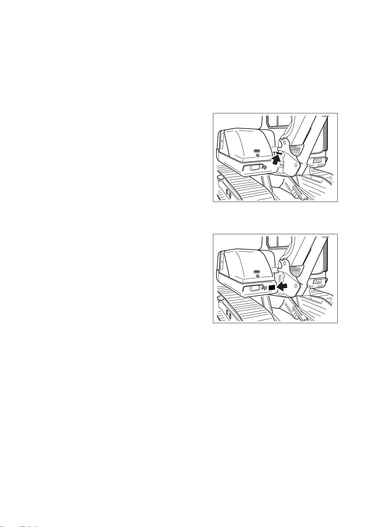
1.4.1 MACHINE SERIAL NUMBER
The machine serial num ber is stamped on the front right par t of
the main frame.
RYA14760
1.4.2 MACHINE IDENTIFICATION PLATE
The Komatsu Utility EXCAVATORS described in this manual are
provided with the CE mark, which certifies that they are in compliance with the CE harmonized standards.
The plate with the mar k is applie d onto the fro nt wall of the main
frame, on the right side.
RYA14770
6
PRODUCT IDENTIFICATION
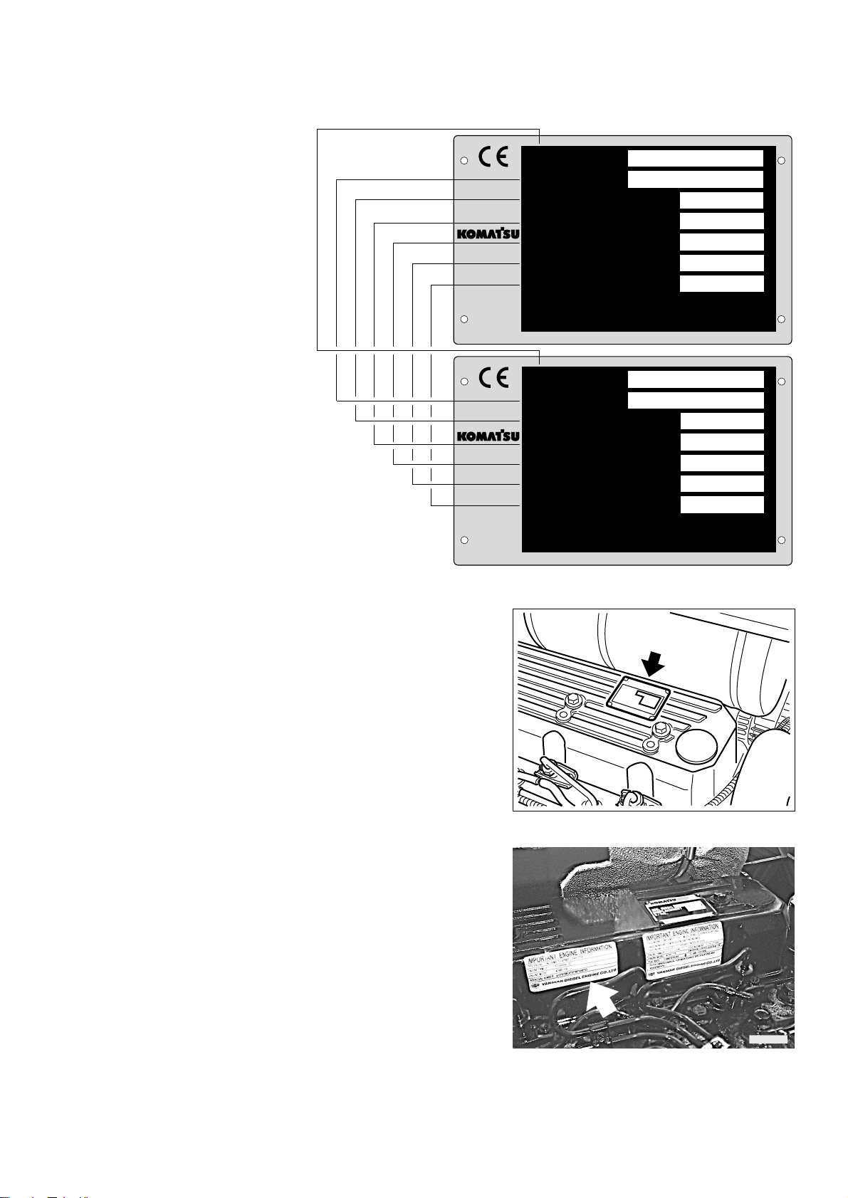
MODELLO - MODEL
TYP - MODELE
MATRICOLA N˚ - SERIAL N˚
FABR. NR. - SERIE NR.
ANNO - YEAR
BAUJAHR - ANNEE
MASSA TOTALE MAX - TOTAL MAX WEIGHT
ZUL. GESAMTGEWICHT - POIDS TOTAL MAX
POTENZA MOTORE - ENGINE POWER
LEISTUNG - PUISSANCE MOTEUR
MASSA MAX ASSE ANT. - MAX WEIGHT FRONT AXLE
ZUL. ACHSLAST VORN - POIDS MAX ESSIEU AV
MASSA MAX ASSE POST. - MAX WEIGHT REAR AXLE
ZUL. ACHSLAST HINTEN - POIDS MAX ESSIEU AR
MANUFACTURED BY KOMATSU UTILITY EUROPE S.p.A.
36025 NOVENTA VICENTINA (VI) ITALY
MODEL
SERIAL N
YEAR
TOTAL MAX WEIGHT
ENGINE POWER
MAX WEIGHT FRONT AXLE
MAX WEIGHT REAR AXLE
MANUFACTURED BY KOMATSU UTILITY EUROPE S.p.A.
36025 NOVENTA VICENTINA (VI) ITALY
kg
kw
kg
kg
21D-98-12580
RWA34270
kg
kw
kg
kg
1.4.3 NGINE SERIAL NUMBER AND EXHAUST GAS EMISSION PLATE
The engine serial number is st amped on the plate positioned on
the upper side of the tappet cover.
The exhaust gas emis sion plate is applied to the front s ide of the
tappet cover.
RWA18500
RWAA9550
7
PRODUCT IDENTIFICATION
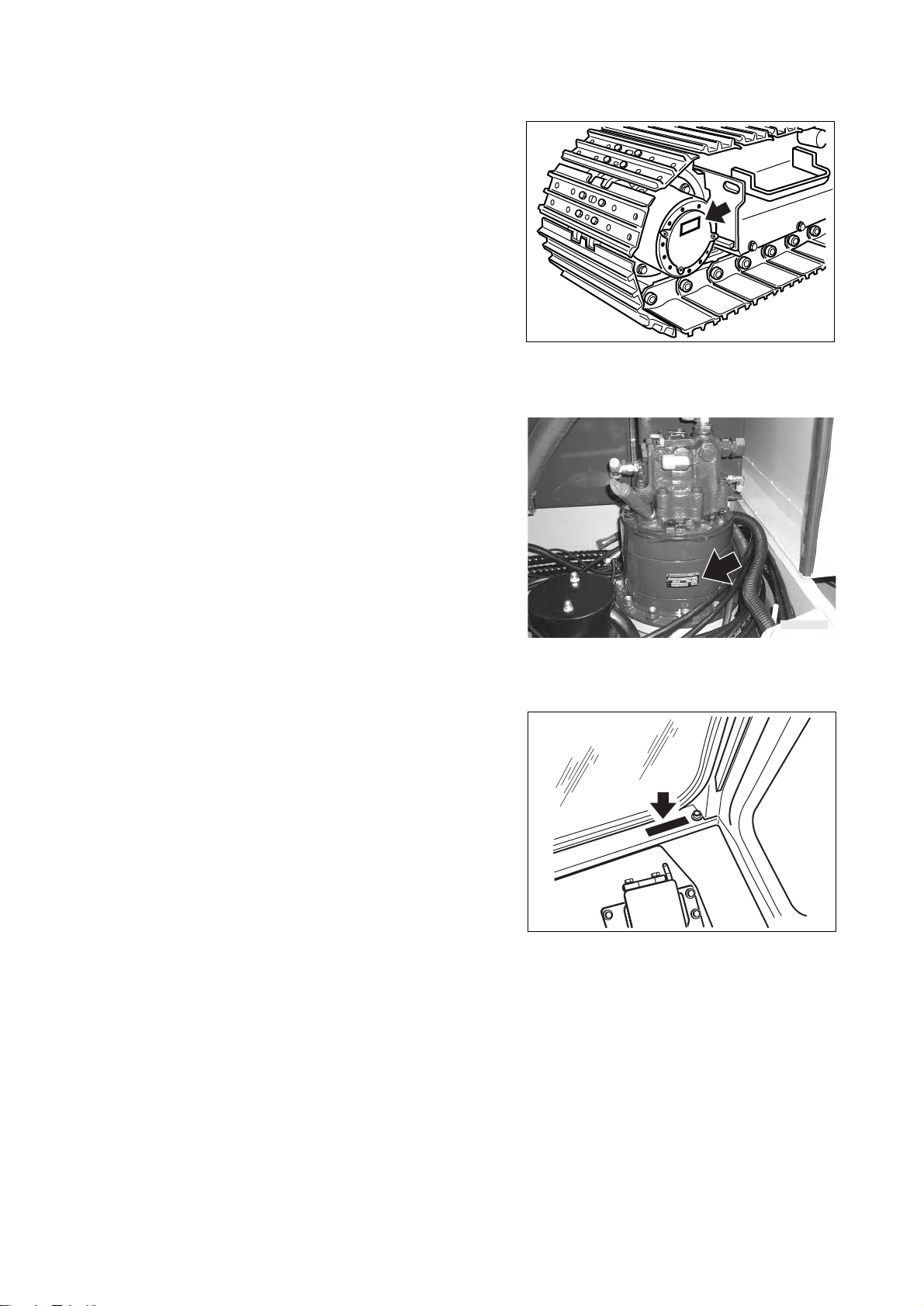
1.4.4 TRAVEL REDUCTION GEAR SERIAL NUMBER
The serial number of the travel red uction gear is stamped on the
plate positioned on the outer side of the reduction gear cover.
1.4.5 SWING REDUCTION GEAR SERIAL NUMBER
The serial number of the swi ng reducti on gear is stamped on the
plate positioned on the side of the reduction gear body.
RWA18210
1.4.6 CAB SERIAL NUMBER
The cab serial number is sta mped on the plat e positioned on the
right side of the front base cross member.
RWAA11980
RWA09430
8

1.4.7 SERIAL NUMBERS AND DEALER’S ADDRESS
Machine n. Model
Engine n.
Travel reduction gear n.
Swing reduction gear n.
Cab n.
Dealer:
PRODUCT IDENTIFICATION
Address
Person to contact:
NOTES:
Tel.
9

CONTENTS
Page
CONTENTS
1.1 FOREWORD . . . . . . . . . . . . . . . . . . . . . . . . . . . . . . . . . . . . . . . . . . . . . . . . . . . . . . . . . . . . . . . . . . . . 1
1.2 INFORMATION ON SAFETY . . . . . . . . . . . . . . . . . . . . . . . . . . . . . . . . . . . . . . . . . . . . . . . . . . . . . . . . 2
1.3 INTRODUCTION . . . . . . . . . . . . . . . . . . . . . . . . . . . . . . . . . . . . . . . . . . . . . . . . . . . . . . . . . . . . . . . . . 4
1.3.1 INTENDED USES . . . . . . . . . . . . . . . . . . . . . . . . . . . . . . . . . . . . . . . . . . . . . . . . . . . . . . . . . . 4
1.3.2 IMPROPER OR UNAUTHORIZED USE . . . . . . . . . . . . . . . . . . . . . . . . . . . . . . . . . . . . . . . . . 4
1.3.3 MAIN CHARACTERISTICS . . . . . . . . . . . . . . . . . . . . . . . . . . . . . . . . . . . . . . . . . . . . . . . . . . 5
1.3.4 RUNNING-IN . . . . . . . . . . . . . . . . . . . . . . . . . . . . . . . . . . . . . . . . . . . . . . . . . . . . . . . . . . . . . 5
1.4 PRODUCT IDENTIFICATION. . . . . . . . . . . . . . . . . . . . . . . . . . . . . . . . . . . . . . . . . . . . . . . . . . . . . . . . 6
1.4.1 MACHINE SERIAL NUMBER . . . . . . . . . . . . . . . . . . . . . . . . . . . . . . . . . . . . . . . . . . . . . . . . . 6
1.4.2 MACHINE IDENTIFICATION PLATE . . . . . . . . . . . . . . . . . . . . . . . . . . . . . . . . . . . . . . . . . . . 6
1.4.3 NGINE SERIAL NUMBER AND EXHAUST GAS EMISSION PLATE . . . . . . . . . . . . . . . . . . 7
1.4.4 TRAVEL REDUCTION GEAR SERIAL NUMBER . . . . . . . . . . . . . . . . . . . . . . . . . . . . . . . . . 8
1.4.5 SWING REDUCTION GEAR SERIAL NUMBER. . . . . . . . . . . . . . . . . . . . . . . . . . . . . . . . . . . 8
1.4.6 CAB SERIAL NUMBER . . . . . . . . . . . . . . . . . . . . . . . . . . . . . . . . . . . . . . . . . . . . . . . . . . . . . . 8
1.4.7 SERIAL NUMBERS AND DEALER’S ADDRESS . . . . . . . . . . . . . . . . . . . . . . . . . . . . . . . . . . 9
SAFETY AND ACCIDENT PREVENTION
2.1 SAFETY, NOISE AND VIBRATION PLATES . . . . . . . . . . . . . . . . . . . . . . . . . . . . . . . . . . . . . . . . . . . 18
2.1.1 POSITION OF THE SAFETY PLATES . . . . . . . . . . . . . . . . . . . . . . . . . . . . . . . . . . . . . . . . . . 18
2.1.2 PICTOGRAMS AND RELEVANT MEANINGS . . . . . . . . . . . . . . . . . . . . . . . . . . . . . . . . . . . . 19
2.1.3 POSITION OF THE NOISE PLATES. . . . . . . . . . . . . . . . . . . . . . . . . . . . . . . . . . . . . . . . . . . . 23
2.1.4 VIBRATIONS TO WHICH THE OPERATOR IS SUBJECTED . . . . . . . . . . . . . . . . . . . . . . . . 24
2.2 GENERAL PRECAUTIONS . . . . . . . . . . . . . . . . . . . . . . . . . . . . . . . . . . . . . . . . . . . . . . . . . . . . . . . . . 25
2.2.1 GENERAL SAFETY RULES . . . . . . . . . . . . . . . . . . . . . . . . . . . . . . . . . . . . . . . . . . . . . . . . . . 25
2.2.2 SAFETY DEVICES AND GUARDS . . . . . . . . . . . . . . . . . . . . . . . . . . . . . . . . . . . . . . . . . . . . 25
2.2.3 CLOTHING AND PERSONAL PROTECTION ITEMS. . . . . . . . . . . . . . . . . . . . . . . . . . . . . . . 25
2.2.4 UNAUTHORIZED MODIFICATIONS . . . . . . . . . . . . . . . . . . . . . . . . . . . . . . . . . . . . . . . . . . . 26
2.2.5 LEAVING THE OPERATOR’S SEAT . . . . . . . . . . . . . . . . . . . . . . . . . . . . . . . . . . . . . . . . . . . 26
2.2.6 GETTING ON AND OFF THE MACHINE . . . . . . . . . . . . . . . . . . . . . . . . . . . . . . . . . . . . . . . . 27
2.2.7 PREVENTING FIRES DUE TO FUEL AND OIL . . . . . . . . . . . . . . . . . . . . . . . . . . . . . . . . . . . 27
2.2.8 PREVENTING BURNS . . . . . . . . . . . . . . . . . . . . . . . . . . . . . . . . . . . . . . . . . . . . . . . . . . . . . . 28
2.2.9 PREVENTING DAMAGE DUE TO ASBESTOS POWDER. . . . . . . . . . . . . . . . . . . . . . . . . . . 28
2.2.10 PREVENTING DAMAGE CAUSED BY THE WORK EQUIPMENT. . . . . . . . . . . . . . . . . . . . . 29
2.2.11 FIRE EXTINGUISHERS AND FIRST AID KIT. . . . . . . . . . . . . . . . . . . . . . . . . . . . . . . . . . . . . 29
2.2.12 PRECAUTIONS CONCERNING THE CAB STRUCTURE . . . . . . . . . . . . . . . . . . . . . . . . . . . 29
2.2.13 PRECAUTIONS CONCERNING THE EQUIPMENT. . . . . . . . . . . . . . . . . . . . . . . . . . . . . . . . 29
2.3 PRECAUTIONS TO BE TAKEN BEFORE STARTING THE ENGINE . . . . . . . . . . . . . . . . . . . . . . . . 30
2.3.1 SAFETY ON THE WORK SITE . . . . . . . . . . . . . . . . . . . . . . . . . . . . . . . . . . . . . . . . . . . . . . . 30
2.3.2 FIRE PREVENTION . . . . . . . . . . . . . . . . . . . . . . . . . . . . . . . . . . . . . . . . . . . . . . . . . . . . . . . . 30
2.3.3 PRECAUTIONS TO BE TAKEN FOR THE OPERATOR'S CAB. . . . . . . . . . . . . . . . . . . . . . . 30
2.3.4 ROOM VENTILATION. . . . . . . . . . . . . . . . . . . . . . . . . . . . . . . . . . . . . . . . . . . . . . . . . . . . . . . 31
2.3.5 PRECAUTIONS TO BE TAKEN FOR THE LIGHTS . . . . . . . . . . . . . . . . . . . . . . . . . . . . . . . 31
2.3.6 CLEANING THE WINDOWS AND THE REAR-VIEW MIRRORS - CHECKING
THE WINDSHIELD WIPER BLADES . . . . . . . . . . . . . . . . . . . . . . . . . . . . . . . . . . . . . . . . . . . 31
10

CONTENTS
Page
2.4 PRECAUTIONS TO BE TAKEN WHEN WORKING . . . . . . . . . . . . . . . . . . . . . . . . . . . . . . . . . . . . . . 32
2.4.1 STARTING THE ENGINE . . . . . . . . . . . . . . . . . . . . . . . . . . . . . . . . . . . . . . . . . . . . . . . . . . . . 32
2.4.2 CHECK THE DIRECTION BEFORE STARTING THE MACHINE. . . . . . . . . . . . . . . . . . . . . . 32
2.4.3 CHECKS FOR TRAVELLING IN REVERSE . . . . . . . . . . . . . . . . . . . . . . . . . . . . . . . . . . . . . 32
2.4.4 MOVING THE MACHINE. . . . . . . . . . . . . . . . . . . . . . . . . . . . . . . . . . . . . . . . . . . . . . . . . . . . . 33
2.4.5 MOVING ON SLOPES. . . . . . . . . . . . . . . . . . . . . . . . . . . . . . . . . . . . . . . . . . . . . . . . . . . . . . . 34
2.4.6 WORKING ON SLOPES . . . . . . . . . . . . . . . . . . . . . . . . . . . . . . . . . . . . . . . . . . . . . . . . . . . . . 35
2.4.7 UNAUTHORIZED OPERATIONSE . . . . . . . . . . . . . . . . . . . . . . . . . . . . . . . . . . . . . . . . . . . . . 35
2.4.8 PREVENTING ELECTROCUTION . . . . . . . . . . . . . . . . . . . . . . . . . . . . . . . . . . . . . . . . . . . . . 36
2.4.9 VISIBILITY . . . . . . . . . . . . . . . . . . . . . . . . . . . . . . . . . . . . . . . . . . . . . . . . . . . . . . . . . . . . . . . 37
2.4.10 WORKING ON ICY OR SNOW-COVERED SURFACES . . . . . . . . . . . . . . . . . . . . . . . . . . . . 37
2.4.11 PREVENTING DAMAGE CAUSED BY THE WORK EQUIPMENT . . . . . . . . . . . . . . . . . . . . 37
2.4.12 WORKING ON LOOSE GROUND. . . . . . . . . . . . . . . . . . . . . . . . . . . . . . . . . . . . . . . . . . . . . . 37
2.4.13 PARKING THE MACHINE. . . . . . . . . . . . . . . . . . . . . . . . . . . . . . . . . . . . . . . . . . . . . . . . . . . . 38
2.5 TRANSPORTING THE MACHINE ON OTHER VEHICLES. . . . . . . . . . . . . . . . . . . . . . . . . . . . . . . . . 39
2.5.1 LOADING AND UNLOADING THE MACHINE . . . . . . . . . . . . . . . . . . . . . . . . . . . . . . . . . . . 39
2.5.2 SHIPPING . . . . . . . . . . . . . . . . . . . . . . . . . . . . . . . . . . . . . . . . . . . . . . . . . . . . . . . . . . . . . . . . 39
2.6 BATTERY . . . . . . . . . . . . . . . . . . . . . . . . . . . . . . . . . . . . . . . . . . . . . . . . . . . . . . . . . . . . . . . . . . . . . . . 40
2.6.1 SAFETY PRECAUTIONS FOR WORK ON BATTERIES . . . . . . . . . . . . . . . . . . . . . . . . . . . . 40
2.6.2 STARTING WITH BOOSTER CABLES . . . . . . . . . . . . . . . . . . . . . . . . . . . . . . . . . . . . . . . . . 40
2.7 PRECAUTIONS FOR EMERGENCY RECOVERY . . . . . . . . . . . . . . . . . . . . . . . . . . . . . . . . . . . . . . . 41
2.8 PRECAUTIONS TO BE TAKEN DURING MAINTENANCE . . . . . . . . . . . . . . . . . . . . . . . . . . . . . . . . 42
2.8.1 WARNING PLATES. . . . . . . . . . . . . . . . . . . . . . . . . . . . . . . . . . . . . . . . . . . . . . . . . . . . . . . . . 42
2.8.2 TOOLS. . . . . . . . . . . . . . . . . . . . . . . . . . . . . . . . . . . . . . . . . . . . . . . . . . . . . . . . . . . . . . . . . . . 42
2.8.3 PERSONNEL . . . . . . . . . . . . . . . . . . . . . . . . . . . . . . . . . . . . . . . . . . . . . . . . . . . . . . . . . . . . . 42
2.8.4 EQUIPMENT . . . . . . . . . . . . . . . . . . . . . . . . . . . . . . . . . . . . . . . . . . . . . . . . . . . . . . . . . . . . . . 43
2.8.5 WORKING UNDER THE MACHINE . . . . . . . . . . . . . . . . . . . . . . . . . . . . . . . . . . . . . . . . . . . . 43
2.8.6 KEEPING THE MACHINE CLEAN . . . . . . . . . . . . . . . . . . . . . . . . . . . . . . . . . . . . . . . . . . . . . 43
2.8.7 USE OF THE ENGINE DURING MAINTENANCE . . . . . . . . . . . . . . . . . . . . . . . . . . . . . . . . . 44
2.8.8 PERIODICAL CHANGE OF THE PARTS THAT ARE CRITICAL FOR SAFETY . . . . . . . . . . 44
2.8.9 STOP THE ENGINE BEFORE CARRYING OUT ANY MAINTENANCE OPERATION
OR INSPECTION. . . . . . . . . . . . . . . . . . . . . . . . . . . . . . . . . . . . . . . . . . . . . . . . . . . . . . . . . . . 44
2.8.10 RULES FOR REFUELLING AND ADDING OIL . . . . . . . . . . . . . . . . . . . . . . . . . . . . . . . . . . . 45
2.8.11 CHECKING THE COOLANT LEVEL IN THE RADIATOR. . . . . . . . . . . . . . . . . . . . . . . . . . . . 45
2.8.12 USING LAMPS . . . . . . . . . . . . . . . . . . . . . . . . . . . . . . . . . . . . . . . . . . . . . . . . . . . . . . . . . . . . 45
2.8.13 PRECAUTIONS CONCERNING THE BATTERY AND THE ALTERNATOR . . . . . . . . . . . . . 46
2.8.14 PRECAUTIONS CONCERNING THE STARTER . . . . . . . . . . . . . . . . . . . . . . . . . . . . . . . . . . 46
2.8.15 PRECAUTIONS CONCERNING HIGH-PRESSURE HOSES . . . . . . . . . . . . . . . . . . . . . . . . 47
2.8.16 PRECAUTIONS TO BE TAKEN WHEN WORKING ON HIGH-PRESSURE SYSTEMSE . . . 47
2.8.17 PRECAUTIONS FOR MAINTENANCE WORK INVOLVING HIGH TEMPERATURES
AND PRESSURES . . . . . . . . . . . . . . . . . . . . . . . . . . . . . . . . . . . . . . . . . . . . . . . . . . . . . . . . . 47
2.8.18 COOLING FAN AND FAN BELT . . . . . . . . . . . . . . . . . . . . . . . . . . . . . . . . . . . . . . . . . . . . . . . 48
2.8.19 WASTE MATERIALS. . . . . . . . . . . . . . . . . . . . . . . . . . . . . . . . . . . . . . . . . . . . . . . . . . . . . . . . 48
2.8.20 PRECAUTIONS FOR THE USE OF THE SYNTHETIC BIODEGRADABLE OIL
TYPE HEES . . . . . . . . . . . . . . . . . . . . . . . . . . . . . . . . . . . . . . . . . . . . . . . . . . . . . . . . . . . . . . 48
11

CONTENTS
Page
DESCRIPTION AND USE OF THE MACHINE
3.1 SAFETY LOCKS. . . . . . . . . . . . . . . . . . . . . . . . . . . . . . . . . . . . . . . . . . . . . . . . . . . . . . . . . . . . . . . . . . 50
3.1.1 MACHINE LOCKS . . . . . . . . . . . . . . . . . . . . . . . . . . . . . . . . . . . . . . . . . . . . . . . . . . . . . . . . . . 50
3.2 GENERAL VIEWS . . . . . . . . . . . . . . . . . . . . . . . . . . . . . . . . . . . . . . . . . . . . . . . . . . . . . . . . . . . . . . . . 51
3.2.1 FRONT GENERAL VIEW (MONOBOOM) . . . . . . . . . . . . . . . . . . . . . . . . . . . . . . . . . . . . . . . 51
3.2.2 FRONT GENERAL VIEW (TWO-PIECE BOOM) . . . . . . . . . . . . . . . . . . . . . . . . . . . . . . . . . . 52
3.2.3 CAB INSIDE GENERAL VIEW . . . . . . . . . . . . . . . . . . . . . . . . . . . . . . . . . . . . . . . . . . . . . . . . 53
3.3 INSTRUMENTS AND CONTROLS . . . . . . . . . . . . . . . . . . . . . . . . . . . . . . . . . . . . . . . . . . . . . . . . . . . 55
3.3.1 INSTRUMENTS. . . . . . . . . . . . . . . . . . . . . . . . . . . . . . . . . . . . . . . . . . . . . . . . . . . . . . . . . . . . 55
3.3.2 WARNING LIGHTS . . . . . . . . . . . . . . . . . . . . . . . . . . . . . . . . . . . . . . . . . . . . . . . . . . . . . . . . . 57
3.3.3 SWITCHES AND PUSH BUTTONS . . . . . . . . . . . . . . . . . . . . . . . . . . . . . . . . . . . . . . . . . . . 59
3.3.4 ELECTRICAL ACCESSORIES . . . . . . . . . . . . . . . . . . . . . . . . . . . . . . . . . . . . . . . . . . . . . . . . 67
3.3.5 MACHINE CONTROLS . . . . . . . . . . . . . . . . . . . . . . . . . . . . . . . . . . . . . . . . . . . . . . . . . . . . . 69
3.4 FUSES AND RELAYS . . . . . . . . . . . . . . . . . . . . . . . . . . . . . . . . . . . . . . . . . . . . . . . . . . . . . . . . . . . . . 77
3.4.1 CENTRAL UNIT FUSES AND RELAYS . . . . . . . . . . . . . . . . . . . . . . . . . . . . . . . . . . . . . . . . . 77
3.4.1.1 CENTRAL UNIT FUSES . . . . . . . . . . . . . . . . . . . . . . . . . . . . . . . . . . . . . . . . . . . . 78
3.4.1.2 CENTRAL UNIT RELAYS . . . . . . . . . . . . . . . . . . . . . . . . . . . . . . . . . . . . . . . . . . . 79
3.4.2 ENGINE LINE FUSES AND RELAYS . . . . . . . . . . . . . . . . . . . . . . . . . . . . . . . . . . . . . . . . . . 80
3.4.2.1 ENGINE LINE FUSES . . . . . . . . . . . . . . . . . . . . . . . . . . . . . . . . . . . . . . . . . . . . . 80
3.4.2.2 ENGINE LINE RELAYS . . . . . . . . . . . . . . . . . . . . . . . . . . . . . . . . . . . . . . . . . . . . . 81
3.4.3 FUSES AND RELAYS OF THE AIR CONDITIONING SYSTEM (if provided) . . . . . . . . . . . . 82
3.5 GUARDS AND DRIVER’S SEAT . . . . . . . . . . . . . . . . . . . . . . . . . . . . . . . . . . . . . . . . . . . . . . . . . . . . 84
3.5.1 ENGINE HOOD . . . . . . . . . . . . . . . . . . . . . . . . . . . . . . . . . . . . . . . . . . . . . . . . . . . . . . . . . . . 84
3.5.2 SIDE COVER . . . . . . . . . . . . . . . . . . . . . . . . . . . . . . . . . . . . . . . . . . . . . . . . . . . . . . . . . . . . . 84
3.5.3 CAB . . . . . . . . . . . . . . . . . . . . . . . . . . . . . . . . . . . . . . . . . . . . . . . . . . . . . . . . . . . . . . . . . . . . . 85
3.5.4 VENTILATION AND HEATING . . . . . . . . . . . . . . . . . . . . . . . . . . . . . . . . . . . . . . . . . . . . . . . . 89
3.5.5 AIR CONDITIONER (if provided) . . . . . . . . . . . . . . . . . . . . . . . . . . . . . . . . . . . . . . . . . . . . . . 90
3.5.6 SEAT . . . . . . . . . . . . . . . . . . . . . . . . . . . . . . . . . . . . . . . . . . . . . . . . . . . . . . . . . . . . . . . . . . . 92
3.5.7 SAFETY BELT . . . . . . . . . . . . . . . . . . . . . . . . . . . . . . . . . . . . . . . . . . . . . . . . . . . . . . . . . . . . 93
3.5.8 EMERGENCY EXIT. . . . . . . . . . . . . . . . . . . . . . . . . . . . . . . . . . . . . . . . . . . . . . . . . . . . . . . . . 93
3.5.9 TECHNICAL DOCUMENTATION CASE. . . . . . . . . . . . . . . . . . . . . . . . . . . . . . . . . . . . . . . . . 94
3.5.10 FIRE EXTINGUISHER. . . . . . . . . . . . . . . . . . . . . . . . . . . . . . . . . . . . . . . . . . . . . . . . . . . . . . . 94
3.5.11 FIRST AID KIT . . . . . . . . . . . . . . . . . . . . . . . . . . . . . . . . . . . . . . . . . . . . . . . . . . . . . . . . . . . . 94
3.6 USE OF THE MACHINE. . . . . . . . . . . . . . . . . . . . . . . . . . . . . . . . . . . . . . . . . . . . . . . . . . . . . . . . . . . . 95
3.6.1 CHECKS BEFORE STARTING THE ENGINE . . . . . . . . . . . . . . . . . . . . . . . . . . . . . . . . . . . . 95
3.6.1.1 VISUAL CHECKS. . . . . . . . . . . . . . . . . . . . . . . . . . . . . . . . . . . . . . . . . . . . . . . . . . 95
3.6.1.2 DAILY CHECKS . . . . . . . . . . . . . . . . . . . . . . . . . . . . . . . . . . . . . . . . . . . . . . . . . . . 95
3.6.1.3 OPERATIONAL CHECKS . . . . . . . . . . . . . . . . . . . . . . . . . . . . . . . . . . . . . . . . . . . 96
3.6.2 STARTING THE ENGINE . . . . . . . . . . . . . . . . . . . . . . . . . . . . . . . . . . . . . . . . . . . . . . . . . . . . 97
3.6.2.1 STARTING WITH WARM ENGINE OR IN TEMPERATE CLIMATES . . . . . . . . . 97
3.6.2.2 STARTING WITH COLD ENGINE OR IN COLD CLIMATES . . . . . . . . . . . . . . . . 98
3.6.3 WARMING THE ENGINE . . . . . . . . . . . . . . . . . . . . . . . . . . . . . . . . . . . . . . . . . . . . . . . . . . . . 99
3.6.4 HEATING THE HYDRAULIC OIL . . . . . . . . . . . . . . . . . . . . . . . . . . . . . . . . . . . . . . . . . . . . . . 99
3.6.5 HOW TO MOVE THE MACHINE. . . . . . . . . . . . . . . . . . . . . . . . . . . . . . . . . . . . . . . . . . . . . . . 99
3.6.5.1 STEERING (CHANGING DIRECTION) . . . . . . . . . . . . . . . . . . . . . . . . . . . . . . . . . 101
3.6.5.2 MOVING ON SLOPES . . . . . . . . . . . . . . . . . . . . . . . . . . . . . . . . . . . . . . . . . . . . . . 102
3.6.5.3 MAXIMUM IMMERSION DEPTH . . . . . . . . . . . . . . . . . . . . . . . . . . . . . . . . . . . . . 103
12

CONTENTS
Page
3.7 PARKING THE MACHINE . . . . . . . . . . . . . . . . . . . . . . . . . . . . . . . . . . . . . . . . . . . . . . . . . . . . . . . . . . 104
3.7.1 PARKING ON LEVEL GROUND . . . . . . . . . . . . . . . . . . . . . . . . . . . . . . . . . . . . . . . . . . . . . . 104
3.7.2 PARKING ON SLOPES . . . . . . . . . . . . . . . . . . . . . . . . . . . . . . . . . . . . . . . . . . . . . . . . . . . . . 105
3.8 STOPPING THE ENGINE. . . . . . . . . . . . . . . . . . . . . . . . . . . . . . . . . . . . . . . . . . . . . . . . . . . . . . . . . . . 106
3.9 TRANSPORTING THE MACHINE ON OTHER VEHICLES. . . . . . . . . . . . . . . . . . . . . . . . . . . . . . . . . 107
3.9.1 LOADING AND UNLOADING THE MACHINE . . . . . . . . . . . . . . . . . . . . . . . . . . . . . . . . . . . . 107
3.9.2 TRANSPORT. . . . . . . . . . . . . . . . . . . . . . . . . . . . . . . . . . . . . . . . . . . . . . . . . . . . . . . . . . . . . . 108
3.10 PRECAUTIONS TO BE TAKEN IN THE COLD SEASON . . . . . . . . . . . . . . . . . . . . . . . . . . . . . . . . . 109
3.10.1 FUEL AND LUBRICANTS . . . . . . . . . . . . . . . . . . . . . . . . . . . . . . . . . . . . . . . . . . . . . . . . . . . . 109
3.10.2 COOLANT . . . . . . . . . . . . . . . . . . . . . . . . . . . . . . . . . . . . . . . . . . . . . . . . . . . . . . . . . . . . . . . . 109
3.10.3 BATTERY . . . . . . . . . . . . . . . . . . . . . . . . . . . . . . . . . . . . . . . . . . . . . . . . . . . . . . . . . . . . . . . . 110
3.10.4 OTHER PRECAUTIONS . . . . . . . . . . . . . . . . . . . . . . . . . . . . . . . . . . . . . . . . . . . . . . . . . . . . 110
3.10.5 PRECAUTIONS TO BE TAKEN AT THE END OF WORK . . . . . . . . . . . . . . . . . . . . . . . . . . 110
3.11 PRECAUTIONS TO BE TAKEN IN THE WARM SEASON . . . . . . . . . . . . . . . . . . . . . . . . . . . . . . . . 111
3.12 USING THE WORK EQUIPMENT . . . . . . . . . . . . . . . . . . . . . . . . . . . . . . . . . . . . . . . . . . . . . . . . . . . . 112
3.12.1 ORGANIZING THE WORK AREA . . . . . . . . . . . . . . . . . . . . . . . . . . . . . . . . . . . . . . . . . . . . . 112
3.12.2 POSITIONING THE BUCKET ACCORDING TO THE WORK TO BE CARRIED OUT. . . . . . 112
3.12.3 POSITIONING THE MACHINE FOR DIGGING OPERATIONS . . . . . . . . . . . . . . . . . . . . . . . 113
3.12.4 DIGGING METHOD. . . . . . . . . . . . . . . . . . . . . . . . . . . . . . . . . . . . . . . . . . . . . . . . . . . . . . . . . 114
3.12.5 CHANGING THE BUCKET . . . . . . . . . . . . . . . . . . . . . . . . . . . . . . . . . . . . . . . . . . . . . . . . . . . 115
3.13 LONG PERIODS OF INACTIVITY . . . . . . . . . . . . . . . . . . . . . . . . . . . . . . . . . . . . . . . . . . . . . . . . . . . . 116
3.13.1 BEFORE THE PERIOD OF INACTIVITY . . . . . . . . . . . . . . . . . . . . . . . . . . . . . . . . . . . . . . . . 116
3.13.2 DURING THE PERIOD OF INACTIVITY . . . . . . . . . . . . . . . . . . . . . . . . . . . . . . . . . . . . . . . . 117
3.13.3 AFTER THE PERIOD OF INACTIVITY . . . . . . . . . . . . . . . . . . . . . . . . . . . . . . . . . . . . . . . . . . 117
3.14 TROUBLESHOOTING . . . . . . . . . . . . . . . . . . . . . . . . . . . . . . . . . . . . . . . . . . . . . . . . . . . . . . . . . . . . . 118
3.14.1 HOW TO REMOVE THE MACHINE . . . . . . . . . . . . . . . . . . . . . . . . . . . . . . . . . . . . . . . . . . . . 118
3.14.2 IF THE FUEL HAS BEEN COMPLETELY DEPLETED . . . . . . . . . . . . . . . . . . . . . . . . . . . . . 118
3.14.3 IF THE BATTERY IS DEPLETED . . . . . . . . . . . . . . . . . . . . . . . . . . . . . . . . . . . . . . . . . . . . . . 119
3.14.3.1 STARTING WITH BOOSTER CABLES . . . . . . . . . . . . . . . . . . . . . . . . . . . . . . . . . 120
3.14.4 OTHER TROUBLES . . . . . . . . . . . . . . . . . . . . . . . . . . . . . . . . . . . . . . . . . . . . . . . . . . . . . . . . 121
3.14.4.1 ELECTRICAL CIRCUIT . . . . . . . . . . . . . . . . . . . . . . . . . . . . . . . . . . . . . . . . . . . . . 121
3.14.4.2 HYDRAULIC SYSTEM. . . . . . . . . . . . . . . . . . . . . . . . . . . . . . . . . . . . . . . . . . . . . . 122
3.14.4.3 ENGINE . . . . . . . . . . . . . . . . . . . . . . . . . . . . . . . . . . . . . . . . . . . . . . . . . . . . . . . . . 123
13

CONTENTS
Page
MAINTENANCE
4.1 GUIDE TO MAINTENANCE . . . . . . . . . . . . . . . . . . . . . . . . . . . . . . . . . . . . . . . . . . . . . . . . . . . . . . . . . 126
4.2 MAINTENANCE NOTES . . . . . . . . . . . . . . . . . . . . . . . . . . . . . . . . . . . . . . . . . . . . . . . . . . . . . . . . . . 128
4.2.1 NOTES REGARDING THE ENGINE . . . . . . . . . . . . . . . . . . . . . . . . . . . . . . . . . . . . . . . . . . . 128
4.2.1.1 ENGINE OIL . . . . . . . . . . . . . . . . . . . . . . . . . . . . . . . . . . . . . . . . . . . . . . . . . . . . . 128
4.2.1.2 COOLANT . . . . . . . . . . . . . . . . . . . . . . . . . . . . . . . . . . . . . . . . . . . . . . . . . . . . . . . 128
4.2.1.3 FUEL . . . . . . . . . . . . . . . . . . . . . . . . . . . . . . . . . . . . . . . . . . . . . . . . . . . . . . . . . . . 129
4.2.2 NOTES REGARDING THE HYDRAULIC SYSTEM . . . . . . . . . . . . . . . . . . . . . . . . . . . . . . . . 129
4.2.3 NOTES REGARDING THE ELECTRICAL SYSTEM. . . . . . . . . . . . . . . . . . . . . . . . . . . . . . . . 130
4.2.4 NOTES REGARDING LUBRICATION. . . . . . . . . . . . . . . . . . . . . . . . . . . . . . . . . . . . . . . . . . . 130
4.2.5 PARTS SUBJECT TO WEAR THAT PERIODICALLY NEED CHANGING . . . . . . . . . . . . . . 131
4.3 FUEL, COOLANT AND LUBRICANTS . . . . . . . . . . . . . . . . . . . . . . . . . . . . . . . . . . . . . . . . . . . . . . . . 132
4.3.1 HOMOLOGATED HEES SYNTHETIC BIODEGRADABLE LUBRICANTS. . . . . . . . . . . . . . . 134
4.4 DRIVING TORQUES FOR SCREWS AND NUTS . . . . . . . . . . . . . . . . . . . . . . . . . . . . . . . . . . . . . . . . 135
4.4.1 STANDARD DRIVING TORQUES . . . . . . . . . . . . . . . . . . . . . . . . . . . . . . . . . . . . . . . . . . . . . 135
4.4.2 SPECIFIC DRIVING TORQUES . . . . . . . . . . . . . . . . . . . . . . . . . . . . . . . . . . . . . . . . . . . . . . . 135
4.5 LUBRICATION . . . . . . . . . . . . . . . . . . . . . . . . . . . . . . . . . . . . . . . . . . . . . . . . . . . . . . . . . . . . . . . . . . . 136
4.5.1 LUBRICATION DIAGRAM . . . . . . . . . . . . . . . . . . . . . . . . . . . . . . . . . . . . . . . . . . . . . . . . . . . 136
4.6 PERIODICAL CHANGE OF THE COMPONENTS CONNECTED WITH SAFETY . . . . . . . . . . . . . . . 137
4.6.1 CRITICAL PARTS FOR SAFETY . . . . . . . . . . . . . . . . . . . . . . . . . . . . . . . . . . . . . . . . . . . . . . 138
4.7 MAINTENANCE PLAN. . . . . . . . . . . . . . . . . . . . . . . . . . . . . . . . . . . . . . . . . . . . . . . . . . . . . . . . . . . . . 141
4.7.1 WHEN REQUIRED . . . . . . . . . . . . . . . . . . . . . . . . . . . . . . . . . . . . . . . . . . . . . . . . . . . . . . . . . 145
4.7.1.a CHECKING, CLEANING OR CHANGING THE AIR CLEANER CARTRIDGE . . . 145
4.7.1.b CHECKING AND CLEANING THE CAB AIR FILTER . . . . . . . . . . . . . . . . . . . . . . 147
4.7.1.c CHECKING AND CLEANING THE AIR RECIRCULATION FILTER
(only for machines equipped with air conditioner) . . . . . . . . . . . . . . . . . . . . . . . . . 148
4.7.1.d CLEANING THE WATER SEPARATOR . . . . . . . . . . . . . . . . . . . . . . . . . . . . . . . . 149
4.7.1.e CHECKING THE STEEL TRACK TENSION . . . . . . . . . . . . . . . . . . . . . . . . . . . . . 150
4.7.1.f CHECKING THE SHOE FASTENING . . . . . . . . . . . . . . . . . . . . . . . . . . . . . . . . . 152
4.7.2 MAINTENANCE INTERVALS IN CASE OF USE OF THE DEMOLITION HAMMER . . . . . . . 153
4.7.2.a CHANGING THE HYDRAULIC OIL FILTER . . . . . . . . . . . . . . . . . . . . . . . . . . . . . 153
4.7.2.b CHANGING THE HYDRAULIC OIL . . . . . . . . . . . . . . . . . . . . . . . . . . . . . . . . . . . . 153
4.7.3 CHECKS BEFORE STARTING . . . . . . . . . . . . . . . . . . . . . . . . . . . . . . . . . . . . . . . . . . . . . . . 154
4.7.3.a VARIOUS CHECKS . . . . . . . . . . . . . . . . . . . . . . . . . . . . . . . . . . . . . . . . . . . . . . . . 154
4.7.3.b CHECKING THE COOLANT LEVEL . . . . . . . . . . . . . . . . . . . . . . . . . . . . . . . . . . . 154
4.7.3.c CHECKING THE FUEL LEVEL . . . . . . . . . . . . . . . . . . . . . . . . . . . . . . . . . . . . . . . 155
4.7.3.d CHECKING THE ENGINE OIL LEVEL . . . . . . . . . . . . . . . . . . . . . . . . . . . . . . . . . 155
4.7.3.e CHECKING THE OIL LEVEL IN THE HYDRAULIC CIRCUIT . . . . . . . . . . . . . . . . 156
4.7.3.f DRAINING THE WATER SEPARATOR. . . . . . . . . . . . . . . . . . . . . . . . . . . . . . . . . 157
4.7.4 MAINTENANCE EVERY 10 HOURS OF OPERATION . . . . . . . . . . . . . . . . . . . . . . . . . . . . . 158
4.7.4.a LUBRICATING THE JOINTS . . . . . . . . . . . . . . . . . . . . . . . . . . . . . . . . . . . . . . . . . 158
4.7.5 MAINTENANCE AFTER THE FIRST 50 HOURS OF OPERATION
(Only for machines in which the synthetic biodegradable oil type HEES is used) . . . . . . . . . 161
14

CONTENTS
Page
4.7.6 MAINTENANCE EVERY 50 HOURS OF OPERATION . . . . . . . . . . . . . . . . . . . . . . . . . . . . . 161
4.7.6.a CHECKING THE RADIATOR FLUID LEVEL . . . . . . . . . . . . . . . . . . . . . . . . . . . . 161
4.7.6.b LUBRICATING THE SWING JOINT . . . . . . . . . . . . . . . . . . . . . . . . . . . . . . . . . . . 162
4.7.6.c CHECKING THE ELECTRICAL SYSTEM . . . . . . . . . . . . . . . . . . . . . . . . . . . . . . . 162
4.7.7 MAINTENANCE EVERY 100 HOURS OF OPERATION . . . . . . . . . . . . . . . . . . . . . . . . . . . . 163
4.7.7.a LUBRICATING THE BALL-BEARING RING . . . . . . . . . . . . . . . . . . . . . . . . . . . . . 163
4.7.8 MAINTENANCE AFTER THE FIRST 250 HOURS OF OPERATION . . . . . . . . . . . . . . . . . . 164
4.7.9 MAINTENANCE EVERY 250 HOURS OF OPERATION . . . . . . . . . . . . . . . . . . . . . . . . . . . . 164
4.7.9.a ADJUSTING THE FAN BELT TENSION . . . . . . . . . . . . . . . . . . . . . . . . . . . . . . . . 164
4.7.9.b ADJUSTING THE TENSION OF THE A/C COMPRESSOR BELT
(only for machines equipped with air conditioner) . . . . . . . . . . . . . . . . . . . . . . . . . 165
4.7.9.c CHECKING THE BATTERY ELECTROLYTE LEVEL . . . . . . . . . . . . . . . . . . . . . . 166
4.7.9.d CHECKING THE OIL LEVEL IN THE TRAVEL REDUCTION GEARS . . . . . . . . . 166
4.7.9.e CHECKING THE OIL LEVEL IN THE SWING REDUCTION GEAR . . . . . . . . . . . 167
4.7.10 MAINTENANCE AFTER THE FIRST 500 HOURS OF OPERATION
(Only for machines in which the synthetic biodegradable oil type HEES is used) . . . . . . . . . 168
4.7.11 MAINTENANCE EVERY 500 HOURS OF OPERATION . . . . . . . . . . . . . . . . . . . . . . . . . . . . 168
4.7.11.a CHANGING THE HYDRAULIC SYSTEM OIL FILTER . . . . . . . . . . . . . . . . . . . . . 168
4.7.11.b CHANGING THE SERVO CONTROL FILTER . . . . . . . . . . . . . . . . . . . . . . . . . . . 170
4.7.11.c CHANGING THE ENGINE OIL. . . . . . . . . . . . . . . . . . . . . . . . . . . . . . . . . . . . . . . . 171
4.7.11.d CHANGING THE ENGINE OIL FILTER . . . . . . . . . . . . . . . . . . . . . . . . . . . . . . . . . 172
4.7.11.e CHANGING THE FUEL FILTER. . . . . . . . . . . . . . . . . . . . . . . . . . . . . . . . . . . . . . . 173
4.7.11.f DRAINING THE FUEL TANK . . . . . . . . . . . . . . . . . . . . . . . . . . . . . . . . . . . . . . . . . 174
4.7.11.g CLEANING THE OUTSIDE OF THE RADIATORS . . . . . . . . . . . . . . . . . . . . . . . . 174
4.7.11.h CLEANING THE OUTSIDE OF THE A/C CONDENSER
(only for machines equipped with air conditioner) . . . . . . . . . . . . . . . . . . . . . . . . 175
4.7.11.j CHECKING THE BALL-BEARING RING PINION LUBRICANT LEVEL . . . . . . . . 176
4.7.11.k DRAINING THE HYDRAULIC OIL TANK (Only for machines in which
the synthetic biodegradable oil type HEES is used) . . . . . . . . . . . . . . . . . . . . . . . 176
4.7.12 MAINTENANCE EVERY 1000 HOURS OF OPERATION . . . . . . . . . . . . . . . . . . . . . . . . . . . 178
4.7.12.a CHECKING AND ADJUSTING THE ENGINE VALVE CLEARANCE . . . . . . . . . . 178
4.7.13 MAINTENANCE EVERY 2000 HOURS OF OPERATION . . . . . . . . . . . . . . . . . . . . . . . . . . 179
4.7.13.a CHANGING THE OIL IN THE TRAVEL REDUCTION GEARS . . . . . . . . . . . . . . . 179
4.7.13.b CHANGING THE OIL IN THE SWING REDUCTION GEAR . . . . . . . . . . . . . . . . . 180
4.7.13.c CHANGING THE HYDRAULIC SYSTEM OIL AND CLEANING THE SUCTION
FILTER . . . . . . . . . . . . . . . . . . . . . . . . . . . . . . . . . . . . . . . . . . . . . . . . . . . . . . . . . 181
4.7.13.d CHANGING THE COOLANT . . . . . . . . . . . . . . . . . . . . . . . . . . . . . . . . . . . . . . . . . 184
4.7.13.e CHANGING THE BALL-BEARING RING PINION LUBRICANT . . . . . . . . . . . . . 185
4.7.13.f CHECKING THE ALTERNATOR AND THE STARTER . . . . . . . . . . . . . . . . . . . . 185
4.7.13.g CHECKING THE A/C COOLING GAS QUANTITY
(only for machines equipped with air conditioner) . . . . . . . . . . . . . . . . . . . . . . . . . 186
4.7.14 MAINTENANCE EVERY 4000 HOURS OF OPERATION . . . . . . . . . . . . . . . . . . . . . . . . . . . 187
4.7.14.a CHANGING THE A/C DEHYDRATOR FILTER
(only for machines equipped with air conditioner) . . . . . . . . . . . . . . . . . . . . . . . . . 187
4.7.14.b CHECKING THE CORRECT OPERATION OF THE A/C COMPRESSOR
(only for machines equipped with air conditioner) . . . . . . . . . . . . . . . . . . . . . . . . . 187
15

CONTENTS
Page
TECHNICAL DATA
5.1 TECHNICAL DATA. . . . . . . . . . . . . . . . . . . . . . . . . . . . . . . . . . . . . . . . . . . . . . . . . . . . . . . . . . . . . . . . 190
5.1.1 STANDARD OVERALL DIMENSIONS . . . . . . . . . . . . . . . . . . . . . . . . . . . . . . . . . . . . . . . . . . 190
5.1.2 TECHNICAL CHARACTERISTICS . . . . . . . . . . . . . . . . . . . . . . . . . . . . . . . . . . . . . . . . . . . . 191
5.1.3 LIFTING CAPACITIES
(Only for machines with overload alarm device) . . . . . . . . . . . . . . . . . . . . . . . . . . . . . . . . . . . 192
5.1.3.1 LIFTING CAPACITY TABLE . . . . . . . . . . . . . . . . . . . . . . . . . . . . . . . . . . . . . . . . . 192
5.1.3.2 LIFTING CAPACITY WITH MONOBOOM . . . . . . . . . . . . . . . . . . . . . . . . . . . . . . . 194
5.1.3.3 LIFTING CAPACITY WITH TWO-PIECE BOOM . . . . . . . . . . . . . . . . . . . . . . . . . 195
AUTHORIZED OPTIONAL EQUIPMENT
6.1 AUTHORIZED OPTIONAL EQUIPMENT. . . . . . . . . . . . . . . . . . . . . . . . . . . . . . . . . . . . . . . . . . . . . . . 198
6.1.1 PRECAUTIONS REGARDING SAFETY . . . . . . . . . . . . . . . . . . . . . . . . . . . . . . . . . . . . . . . . 198
6.1.2 PRECAUTIONS REGARDING THE INSTALLATION OF EQUIPMENT . . . . . . . . . . . . . . . . 199
6.1.3 CHARACTERISTICS OF THE OPTIONAL EQUIPMENT . . . . . . . . . . . . . . . . . . . . . . . . . . . . 200
6.2 ARRANGEMENT FOR THE INSTALLATION OF THE DEMOLITION HAMMER . . . . . . . . . . . . . . . 201
6.2.1 DESCRIPTION AND OPERATION . . . . . . . . . . . . . . . . . . . . . . . . . . . . . . . . . . . . . . . . . . . . . 201
6.2.2 USE OF THE DEMOLITION HAMMER AND RULES TO BE OBSERVED. . . . . . . . . . . . . . . 201
6.2.3 INSTALLING AND REMOVING THE DEMOLITION HAMMER . . . . . . . . . . . . . . . . . . . . . . . 205
6.2.3.1 INSTALLING THE HAMMER . . . . . . . . . . . . . . . . . . . . . . . . . . . . . . . . . . . . . . . . . 205
6.2.3.2 REMOVING THE HAMMER. . . . . . . . . . . . . . . . . . . . . . . . . . . . . . . . . . . . . . . . . . 206
6.2.4 MAINTENANCE . . . . . . . . . . . . . . . . . . . . . . . . . . . . . . . . . . . . . . . . . . . . . . . . . . . . . . . . . . . 206
6.3 CLAMSHELL BUCKET . . . . . . . . . . . . . . . . . . . . . . . . . . . . . . . . . . . . . . . . . . . . . . . . . . . . . . . . . . . . 207
6.3.1 DESCRIPTION AND OPERATION . . . . . . . . . . . . . . . . . . . . . . . . . . . . . . . . . . . . . . . . . . . . . 207
6.3.2 INSTALLING THE CLAMSHELL BUCKET . . . . . . . . . . . . . . . . . . . . . . . . . . . . . . . . . . . . . . . 208
6.3.3 MAINTENANCE. . . . . . . . . . . . . . . . . . . . . . . . . . . . . . . . . . . . . . . . . . . . . . . . . . . . . . . . . . . . 210
16

SAFETY AND
ACCIDENT PREVENTION
17
SAFETY, NOISE AND VIBRATION PLATES
2.1 SAFETY, NOISE AND VIBRATION PLATES
2.1.1 POSITION OF THE SAFETY PLATES
• The safety plates must alway s be le gi ble and i n goo d co ndi ti ons ; for thi s reas on , if th ey are dir ty with dus t, oil or
grease, it is necessary to clean them with a solution made of water and detergent.
Do not use fuel, petrol or solvents.
• If the plates are damaged, ask for new ones to Komatsu Utility or to your Komatsu Utility Dealer.
• In case of replacemen t of a co mponent provided with a sa fety plate , ma ke su re that thi s p late is ap pli ed als o o n
the new piece.
• The machine can be provided with other plates in addition to those indicated below; keep also to the instructions
given in the additional plates, in any case.
18
RYA14780
SAFETY, NOISE AND VIBRATION PLATES
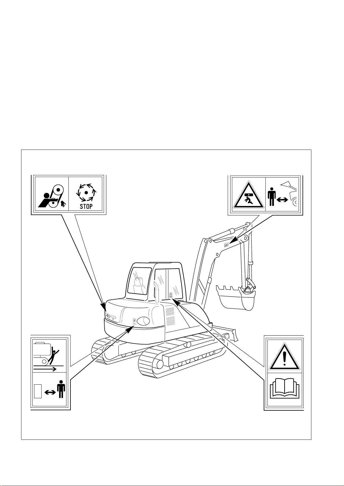
2.1.2 PICTOGRAMS AND RELEVANT MEANINGS
The warning and danger plates applied onto the machine are accompanied or represented by pictograms.
The personnel in charge with th e ope ra tio n and mai nten ance of th e mac hi ne m us t know the sym bol s con tai ned i n
the pictograms perfectly; the following description illustrates what they look like and their respective meanings.
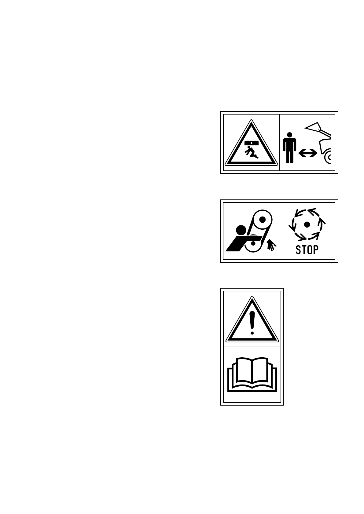
DANGER IN THE WORK AREA
• Do not approach or stand within the equipment operating radius
when the boom and the bucket are raised.
RWA00020
DO NOT OPEN THE HOOD
• Do not open or remove the hood while the engine is running.
CONSULT THE MANUAL
• Carefully read the co ntents of the manual bef ore using th e ma-
chine or performing maintenance operations.
RWA00010
RWA00030
19
SAFETY, NOISE AND VIBRATION PLATES
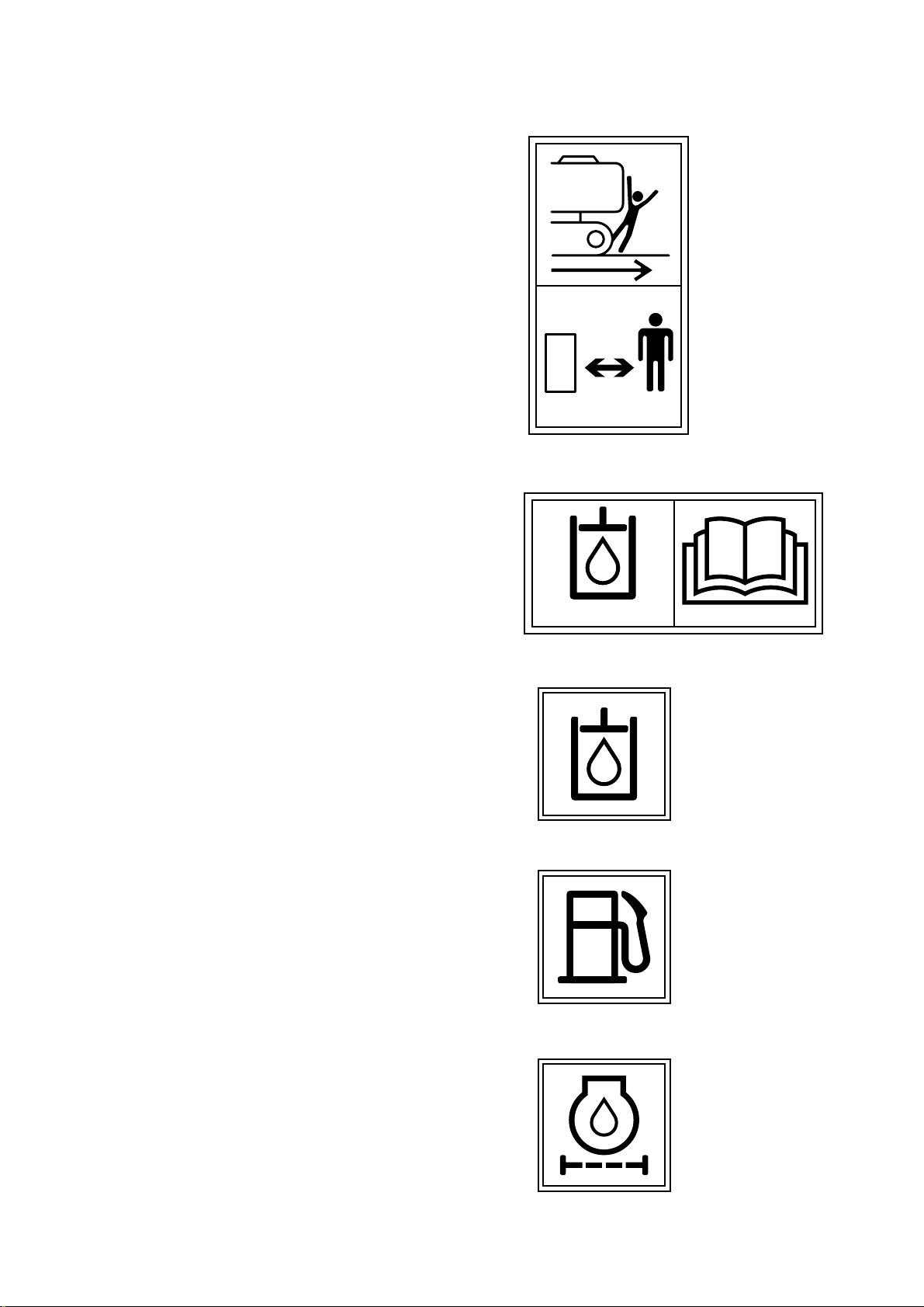
SAFETY DISTANCE
• Do not get near or stand within the machine working area.
FILLING THE HYDRAULIC SYSTEM WITH
OIL
RWA18280
(Only for machines in which the synthetic biodegradable oil
type HEES is used)
HYDRAULIC OIL TOPPING UP
REFUELLING
BIO-OIL
RWA00050
D
RWA00040
RWA34380
ENGINE LUBRICATING OIL FILTER
20
RWA00080
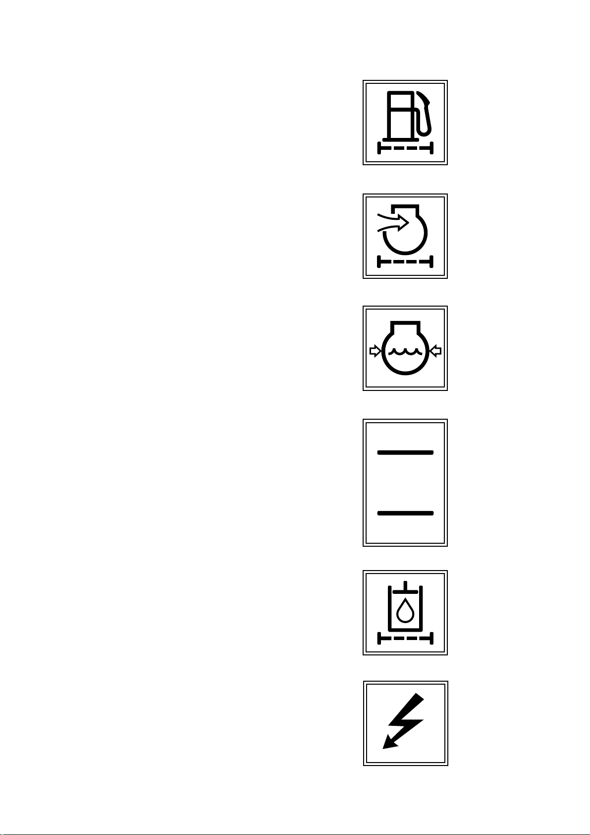
FUEL FILTER
ENGINE AIR SUCTION FILTER
ENGINE COOLANT PRESSURE
SAFETY, NOISE AND VIBRATION PLATES
D
RWA00060
RWA00090
HYDRAULIC OIL LEVEL
HYDRAULIC OIL FILTER
H
L
RWA00110
RYA12880
RWA00070
ELECTRIC OUTLET
RWA00120
12 V
21
SAFETY, NOISE AND VIBRATION PLATES
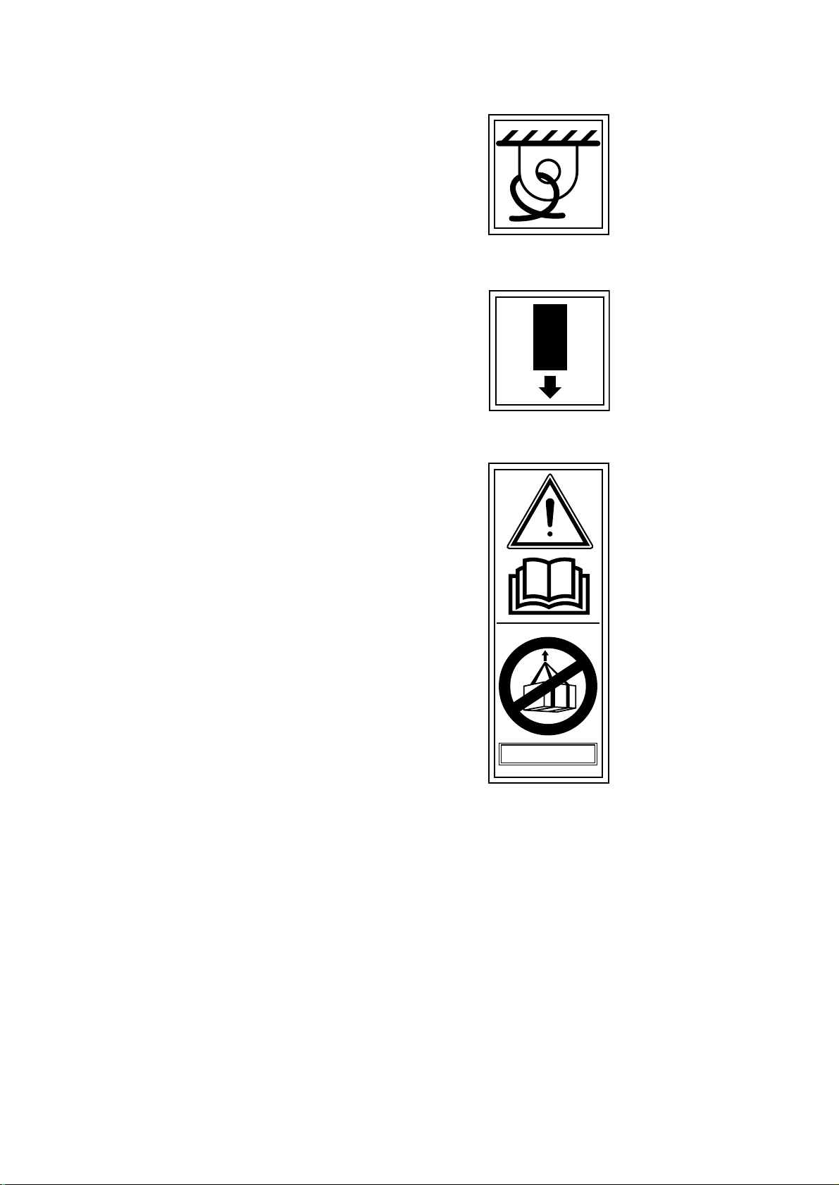
ANCHORAGE POINT
EMERGENCY EXIT
DO NOT LIFT MORE THAN 1000 KG
(Only for machine without overload warning device)
RWA00200
RWA00190
22
> 1000 Kg
RYA12890
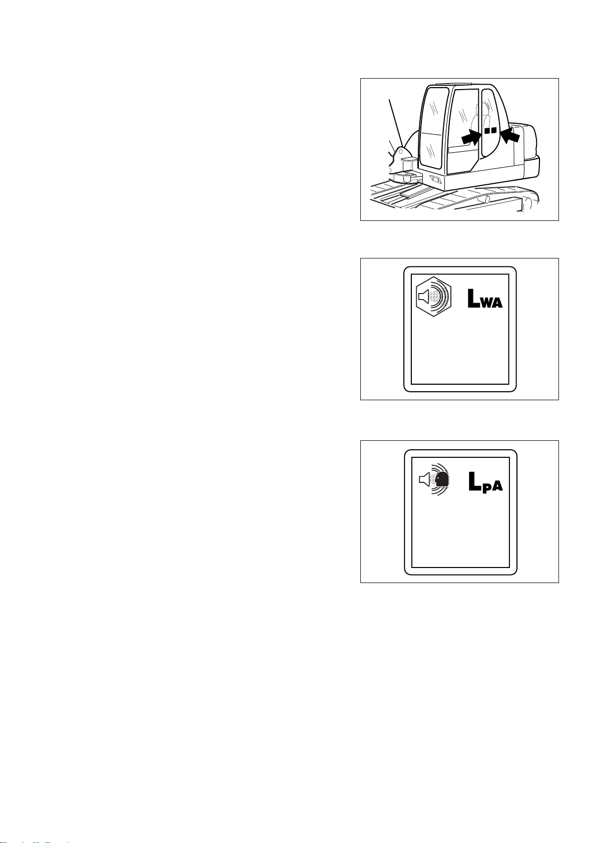
2.1.3 POSITION OF THE NOISE PLATES
• The noise plates must always be legible and in good conditions;
for this reason, if they are dirt y wit h d ust, oil or grea se , it is n ecessary to clean the m with a solution ma de of water and deter gent.
Do not use fuel, petrol or solvents.
• If the plates are damaged, ask for new one s to Komatsu Utility
or to your Komatsu Utility Dealer.
• In case of replacement of a compon ent provided with a noise
plate, make sure that this plate is applied also on the new piece.
NOISE OUTSIDE THE CAB
• This value indicates the noise le vel outside the machine and re-
fers to the noise perceived by the persons who are in the vicinity
of the work area.
SAFETY, NOISE AND VIBRATION PLATES
RYA14790
NOISE INSIDE THE CAB
• This value indic ates the maxi mum noise lev el perceive d by the
operator’s ears inside the cab when this is completely closed.
10
3
2000/14/EC
7
6
ISO 6396
dB
dB
RYA12910
RYA14800
23

SAFETY, NOISE AND VIBRATION PLATES
2.1.4 VIBRATIONS TO WHICH THE OPERATOR IS SUBJECTED
• According to the results of the tests carried out to determine the vibrations transmitted to the operator by the ma-
chine, the upper limbs ar e su bjected to vi brations lower t han 2.5 m/sq. sec., while the seate d par t of the body is
subjected to vibrations lower than 0.5 m/sq.sec.
24
GENERAL PRECAUTIONS
2.2 GENERAL PRECAUTIONS
2.2.1 GENERAL SAFETY RULES
• Only trained and authorized personnel can use the machine and perform maintenance operations.
• Follow all the safety ru les, pr ec au tion s a nd in str u cti ons whe n us ing the ma ch ine or per for ming maintenance op-
erations.
• When working with other op erators or whe n the work site is of ten occupied by othe r operators, m ake sure that
everyone knows and understands all the agreed signals and, in any case, that everyone works in such a way as
to be able to see the machine and to be visible to the operator.
2.2.2 SAFETY DEVICES AND GUARDS
• Make sure that all th e guards and covers ar e in the correct positio n. Have guards and co vers changed or re-
paired if damaged. Neither use the machine without guards, nor remove the guards when the engine is running.
• Always use the proper safety devices to lock the machine when parking and fasten the safety belt.
• For the safety devices, see “3.1 SAFETY LOCKS”.
• For the safety belt, see “3.5.6 SAFETY BELT”.
• Do not remove the safety devices and always keep them in good operating conditions.
• Improper use of the safety devices may result in serious injuries or even death.
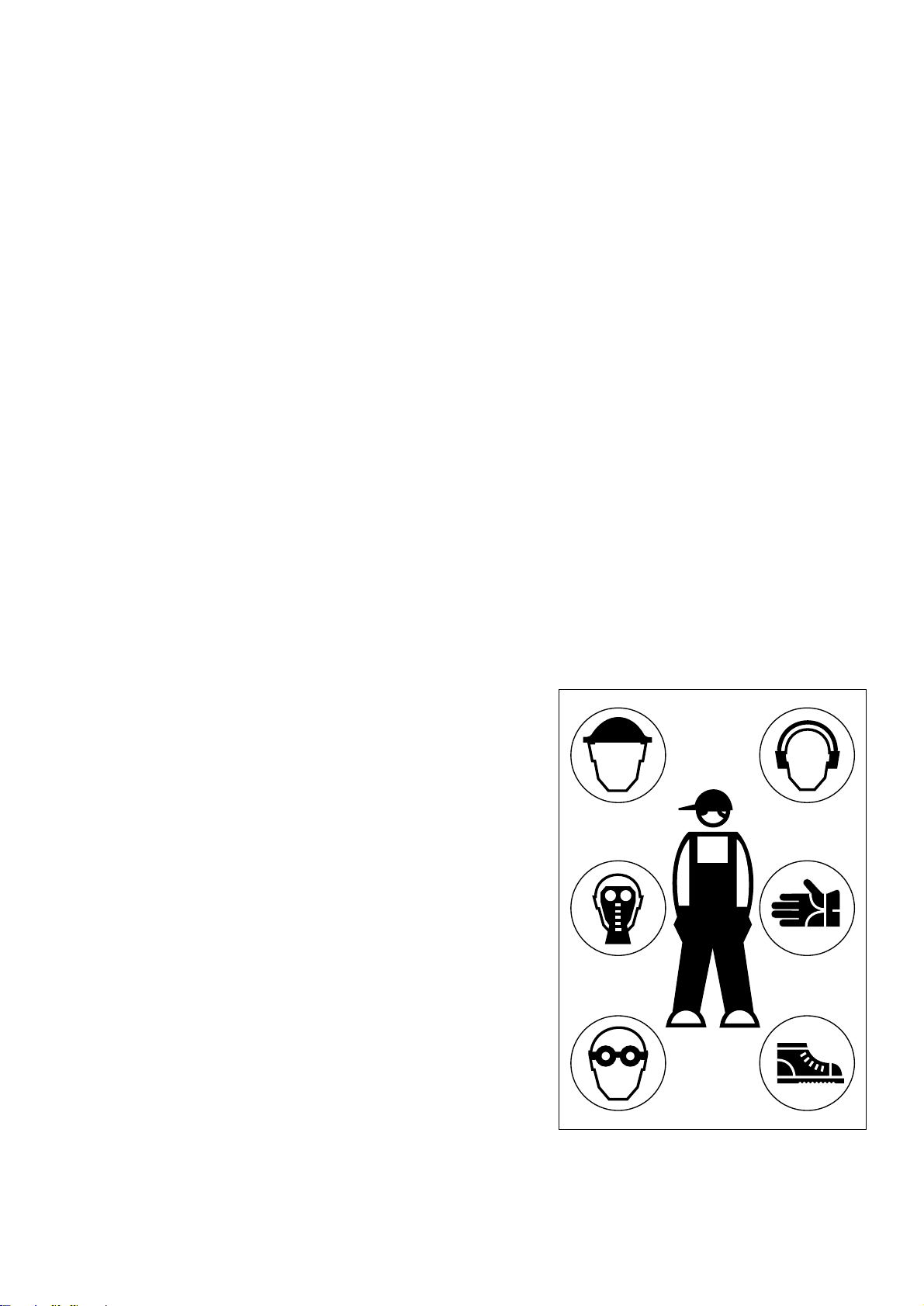
2.2.3 CLOTHING AND PERSONAL PROTECTION ITEMS
• Do not wear large or l oose clothes, rings and w atches and do
not approach the machine with lo ose long hair, since they can
get entagled in the moving parts of the machine and cause serious injuries and damage.
Avoid also wearing clothes dirty with oil or fuel , since they are
flammable.
• Wear a hard hat, goggles, safety shoes, mask, gloves and
headphones when operating the machine or performing maintenance operations.
• Always wear safety goggles, a hard hat and heavy gloves if your
job involves scattering metal chips or minute materials; these
precautions are particular ly useful when driving the equipment
connection pins with a hamm er and whe n blowing co mpressed
air into the air filter and the radiator to clean them.
During these operations, make also sure that no one is standing
or working near the machine without the necessary protections.
• When working for 8 ho ur s with a noise level exc ee din g 90 dB A,
it is necessary to use headphones or ear plugs and to be particularly careful, especially at the end of the work shift.
RWA00960
25
GENERAL PRECAUTIONS
r
2.2.4 UNAUTHORIZED MODIFICATIONS
• Any modification made without the authorization of Komatsu Utility can involve hazards.
• Before making a modification, consult your Komatsu Utility Dealer. Komatsu Utility declines any responsibility for
injuries or damage caused by unautho ri z ed modific ations.
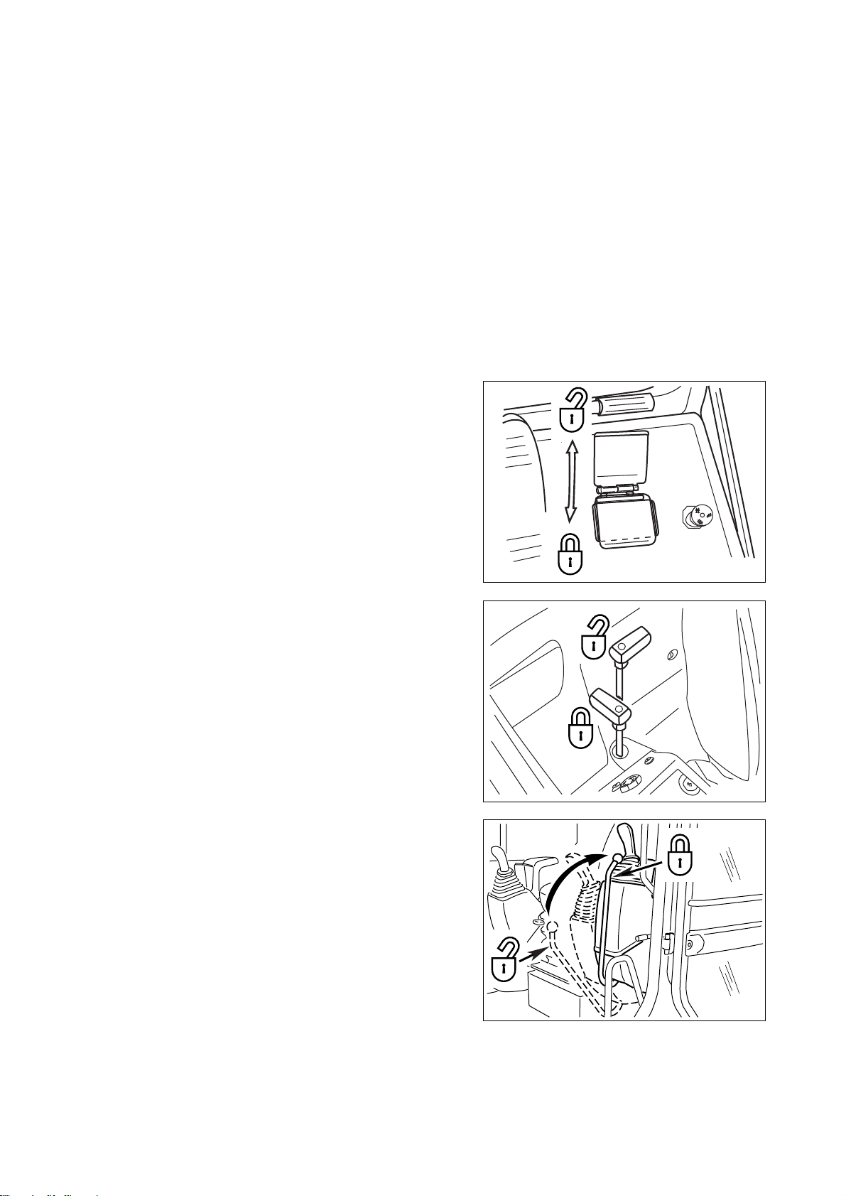
2.2.5 LEAVING THE OPERATOR’S SEAT
• When leaving the operator’s seat, even if temporarily, make sure
that the machine i s in a safe position. (Se e “2.4.13 PARKING
THE MACHINE”).
• Before leaving the operator’s seat, carry out the following opera-
tions in the sequence indicated below:
1 - Rest the equipment onto the ground.
2 - Connect the safety devices of the boom swing control and
engage the upper structure rotation safety pin.
3 - Lock the equipment control by shifting the safety device leve
to the lock position.
4 - Stop the engine (See “3.8 STOPPING THE ENGINE”).
If you have to go so far a way that you will not be able to s ee the
machine, extract the ignition key.
RWA20720
26
RWA18590
RYA12930
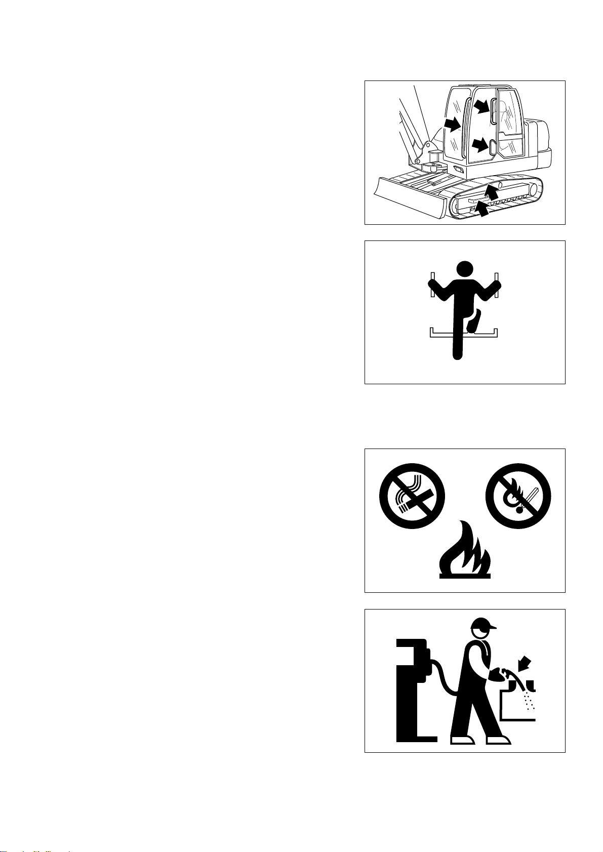
2.2.6 GETTING ON AND OFF THE MACHINE
• Do not jump on or off the machine, either when it is at rest and
when it is moving.
• When getting on or off the machine, always use the handles
and the tracks; get on and off the machine very carefully.
• Never hold or rest on the control levers.
• Either when getting on and when getting off the machine, al-
ways maintain three points of contact (holding or resting points),
in order to avoid losing your balance and falling down.
• Tighten the handle connection screws if they are loose and
clean the handles and tracks if they are dirty with oil or grease.
Carefully clean the cab floor if it is dirty with oil, grease, mud or
rubble.
GENERAL PRECAUTIONS
RYA16180
2.2.7 PREVENTING FIRES DUE TO FUEL AND OIL
Fuel, oil and some types of antifreeze can be easily ignited if they
get in contact with a flame. Fuel is particularly flammable and
therefore extremely hazardous.
• Keep any naked flame away from flammable fluids.
• Stop the engine and do not smoke when refuelling.
• To p up with fuel and oil only after stopping the engine and in
well ventilated areas.
• Top up with fuel and oil in a well delimited area and do not allow
unauthorized persons to approach.
• When refuelling, hold th e fuel gun firmly and keep it constantl y
in contact with the filler until you hav e fi nishe d, in orde r to avoid
sparks due to static electricity.
• After topping up, tighten the safety caps of the fuel and oil tanks
securely.
RWA18670
RWA00970
• Do not fill the tank completely , in order to leave room for the fuel
to expand.
• In case some fuel is spilled, wipe it up immediately.
RWA00980
27
GENERAL PRECAUTIONS
2.2.8 PREVENTING BURNS
• If the engine coolant, the engine oil and the hydraulic oil are hot,
use heavy cloths a nd wear gloves, heavy clothing and safety
goggles before carrying out any check or touching the hot parts.
• Before checking the coo lant level, stop the engine and let the
fluid cool down.
If a check is necessary du e to the overheating of the engine,
slowly loosen the radiato r cap to releas e any residual p ressure
before removing it. The hot fluid that spurts out may cause serious burns.
• Before checking the engine oil and hydraulic circuit oi l levels,
stop the engine and let the oil cool down. The hot oil that can be
sprayed out of the tank may cause serious burns.
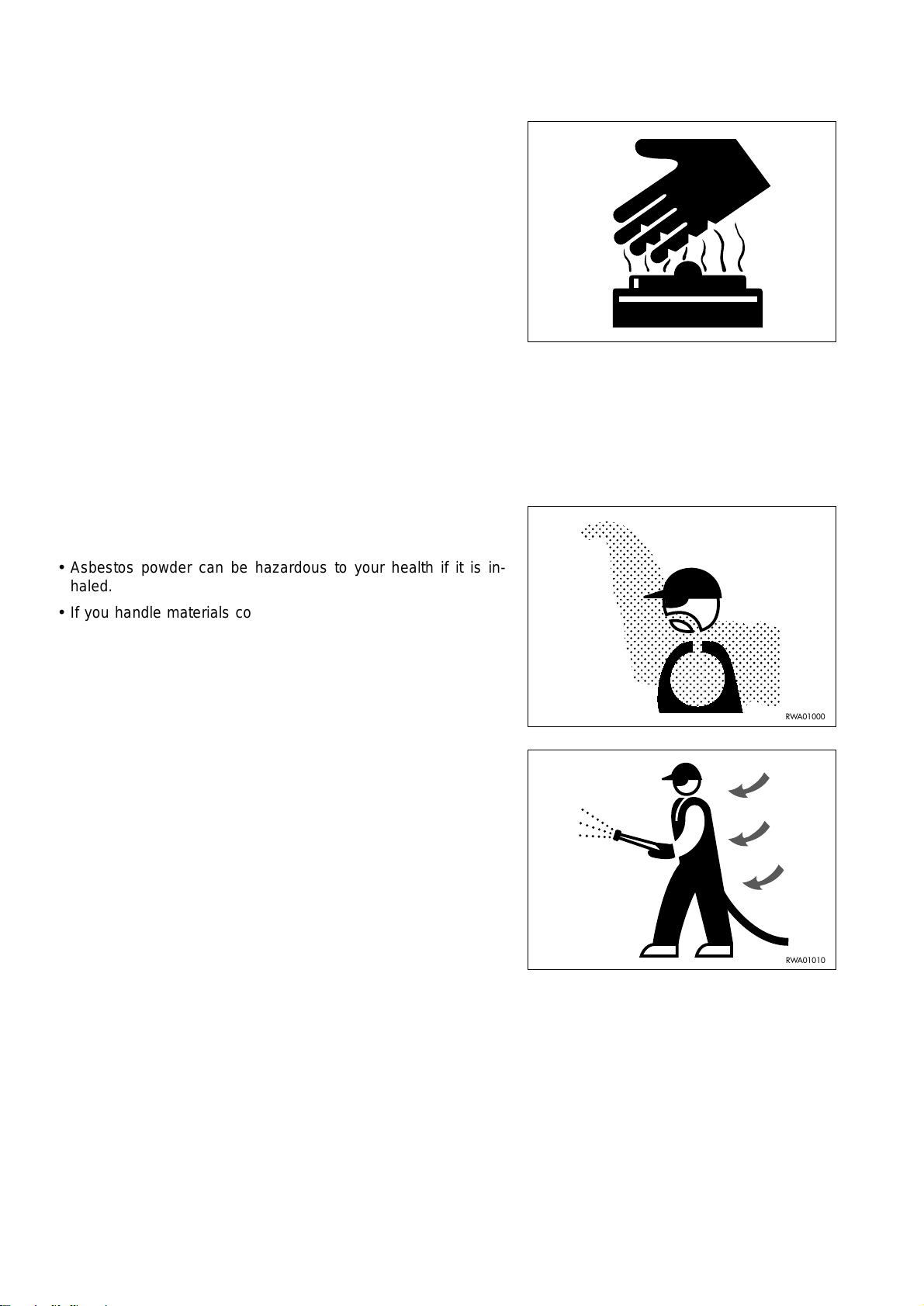
2.2.9 PREVENTING DAMAGE DUE TO ASBESTOS POWDER
RWA00990
• Asbestos powder can be hazardous to your health if it is in-
haled.
• If you handle materials containi ng asbestos fibers, keep to the
instructions given below:
1 - Do n ot use compressed air, but only aspirators to clean the
machine and make sure that the room in which you are
working is properly ventilated.
2 - Use low-pressure water to kee p down the dust when cl ean-
ing.
3 - If there is danger that there m ay be asbestos powder in the
air, operate the machine with the wind to your bac k when ev er possible.
4 - Even if the cab provides suitable protection, use an ap-
proved and homologated respira tor.
5 - The powder gathered during the cleaning operations must
be dampened and put in a sealed and marked container, so
that it can be safely d ispos ed of ac co rding to the regulations
in force.
RWA01000
RWA01010
28

2.2.10 PREVENTING DAMAGE CAUSED BY THE WORK EQUIPMENT
• Do not stand within or approach the operating radius of the
work equipment, even wh en the operator is on board the machine and the engine is running.
• Do not stand or work under the arm s or the articulations when
the arms are lifted, if you are not sure that the safety locks have
been duly engaged.
• Do not carry out any operation requiring the lifting of the arms, if
you are not sure that the locks are correctly positioned and coupled to the arms.
2.2.11 FIRE EXTINGUISHERS AND FIRST AID KIT
• Make sure that fire extinguishers have been provided and check
their position.
• Periodically make sure that the fire extinguishers are loaded
and that you know how to use them.
GENERAL PRECAUTIONS
RWA01020
• Find out where the first aid kit has been located.
• Periodically mak e sure that the first aid ki t contains the neces -
sary disinfectants, bandages, medicins, etc.
• It is necessary to know what to do in case of fire.
• Make sure that you have the phon e numbers of the perso ns or
structures you may nee d to cont act in c ase of an emer gency at
hand (either at the work site and where maintenance operations
are performed).
RWA01030
2.2.12 PRECAUTIONS CONCERNING THE CAB STRUCTURE
• If the cab is inadvertentl y hit or the mach ine overturns during work, the c ab may be damaged wi th conseque nt
reduction of its stiffness and of the safety that must be guaranteed to the operator.
Consult Komatsu Utility or your Komatsu Utility Dealer to have the cab structure and resistance checked in case
of impact or damage.
2.2.13 PRECAUTIONS CONCERNING THE EQUIPMENT
• When installing and us in g o pti onal e qui pme nt, car e full y read the relevant ins tr uct io n m anu al and ke ep to the in-
dications given therein.
• Do not use optional or special equipment without the authorization of Komatsu Utility or the Komatsu Utility Deal-
er.
The installation a nd use of unauthori zed equipment may create safety problems and adversely affect the efficiency and life of the machine.
• Komatsu Utility cannot be held liable for any damage, accident, product failure resulting from the installation and
use of unauthorized equipment.
29

PRECAUTIONS TO BE TAKEN BEFORE STARTING THE ENGINE
r
r
2.3 PRECAUTIONS TO BE TAKEN BEFORE STARTING THE ENGINE
2.3.1 SAFETY ON THE WORK SITE
• Before starting the engine, thoroughly check the area for any
unusual condition of the ground due to which work may be dangerous.
• Check the conditions of the ground at t he work site and before
starting the engine define the work plan and the best and safest
operating procedure.
• Make the ground s urface as level as possible b efore carrying
out any operation.
• In case of work on the road, protect pedestrians and cars by
designating a person for work site traffic duty and install fences
around the work site.
• If water lines, gas lines, and telephone or high-voltage electrical
lines are located under the wor k site, contac t the rel evant utilit y
company in order to find out their exact positions or to make
them inneffective until the end of the o perations. B e caref ul not
to sever or damage any of these lines.
RWA00220
• Check the depth and flow of water before ope rating in water o
on river banks.
2.3.2 FIRE PREVENTION
• Carefully remove all wood chips, rubbish, paper and other flam-
mable materials that may have accumulated inside the engine
compartment, since they can cause fires.
• Check the fuel and hydraulic system p ipes for leak s and if nec -
essary repair them. Wipe up any leakage of oil, fuel or othe
flammable fluids.
• Make sure that fire extinguishers are available in the work area.
2.3.3 PRECAUTIONS TO BE TAKEN FOR THE OPERA TOR’S CAB
RWA01040
• Do not keep objects or tools in the operator’s cab. They may hinder the operation of the controls and cause seri-
ous accidents.
• Keep the cab floor and the controls (pedals and levers) clean, by removing any trace of oil and grease and, as far
as the floor is concerned, remove any excess dirt (earth, stones, etc.).
• Check the safety belt and change it if it is broken or damaged.
Replace any component only with homologated parts available at Komatsu Utility or its Dealers.
30

PRECAUTIONS TO BE TAKEN BEFORE STARTING THE ENGINE
2.3.4 ROOM VENTILATION
• Before starting the machine in confined or poorly ventilated
places, provide for pro per ventilation or connect the eng ine exhaust pipe to a suction duct. The engine exh aust gases ca n be
deadly.
RWA01050
2.3.5 PRECAUTIONS TO BE TAKEN FOR THE LIGHTS
• Remove any trace of dirt from the lights, in such a way as to ensure perfect visibility on the work area.
• Make sure that all the working lights and bul bs are functioni ng properly. If necessary, replace faulty bulbs with
new ones, making sure that the power is correct.
2.3.6 CLEANING THE WINDOWS AND THE REAR-VIEW MIRRORS CHECKING THE WINDSHIELD WIPER BLADES
• Remove any trace of dirt from the cab windows and clean the rear-view mirrors, in order to ensure perfect visibil-
ity on the work area.
• Adjust the rear-view mirrors that may have moved, so that the operator seated in the driving position can clearly
see the area behind the machine.
If any glass is damaged, replace it with a new one.
• Check the conditions of the windshield wiper blades; the scraping wire must be smooth, with no indentations and
attached to the rubber back of the blade.
In case of doubts on the efficiency of the scraping wire, change the blades.
31

PRECAUTIONS TO BE TAKEN WHEN WORKING
r
2.4 PRECAUTIONS TO BE TAKEN WHEN WORKING
2.4.1 STARTING THE ENGINE
• Before getting on the machine, walk around it and check for people and objects that might be in the way.
• Do not start the engine if warning plates have been attached to the control levers.
• When starting the engine, sound the horn as an alert signal.
• Start the engine only when seated with fastened safety belt.
• Do not allow anyone to get on the machine.
2.4.2 CHECK THE DIRECTION BEFORE STARTING THE MACHINE
• Before operating the machine travel levers, check the position of
the blade.
If the blade is positioned on the back side of the machine , the
travel levers must be operated in the opposite direction.
In this condition, be careful not to confuse the travel movements
while using the machine (See “3.6.5 HOW TO MOVE THE MACHINE”).
2.4.3 CHECKS FOR TRAVELLING IN REVERSE
• When operating in ar eas that may be hazardo us or have poo
visibility, designate a person to direct the movements of the machine and traffic on the work site.
• Make sure that no unauthorized pe rson is within the machine
operating radius or in its travel direction.
If necessary, put up appropriate fences.
• Before moving the machine, sound the horn in order to warn the
persons near the work area.
• There are blind spots behind the machine, which cannot be
seen and where som eon e m ay be s ta ndi ng: ther ef ore, i t is n ec essary to make s ure that there is no one behind the machine
before travelling in reverse.
RYA14820
RWA06760
32
RWA06770

2.4.4 MOVING THE MACHINE
• When moving the machi ne, position the front bucket at about
40-50 cm from the ground; this position makes it possible to
evaluate the space r equired for the movemen ts more pr ecisely
and at the same time ensures the stability of the machine.
• Make sure that the cab on the upper structure is directed to-
wards the blade.
Otherwise, pay attention to t he steering and advan ce manoeuvres, since they are inverted.
PRECAUTIONS TO BE TAKEN WHEN WORKING
• If the equipment control levers must be used during travel, avoid
moving them abrupt ly ; s ud den m anoe uv res change the attitu de
of the machine and make driving difficult.
• When travelling on rough ground, keep the speed low and avoid
sudden movements of the bucket arm.
• If possible, avoid moving on obstacles.
If the machine has to travel ov er an obstacle, keep the equipment as close to the ground as possible and travel at low speed.
Never move on obsta cles th at may inc line the machine co nsiderably (over 10°).
• If one of the two tracks moves on an obstacle or gets into a hole
in the ground, the machine may overturn.
In these cases, reduce the speed to minimum and be very careful to the balance of the machine.
40÷50 cm
WRONG
RYA14830
RYA14850
33

PRECAUTIONS TO BE TAKEN WHEN WORKING
2.4.5 MOVING ON SLOPES
• Operations on slopes and on river or lake banks with damp
ground may result in the tipping over or slipping of the machine.
• On hills, banks or slopes, keep the bucket very close to the
ground (20--30 cm from the ground) and in c ase of emergency
quickly lower it to the ground to help the machine stop.
• Do not change direction and avoid travelling obliquely when
working on slopes. It is advisable to go down or up to a flat
place to perform these operations.
• Do not travel on wet grass or thick laye rs of leaves: if the ma-
chine moves obliquely in these conditions, it may slip.
• Do not move on slopes with inclination exceeding 30°, since the
machine may overturn.
• When the fuel level ind icator rea ches the red reserve area dur-
ing work on a slope, immedia tely provide for refuelling; due to
the inclination of the mach ine, the engine may suck in air and
suddenly stop, whic h represents a grave risk for the safety of
the operator and of the persons before the machine.
• If the engine shou ld s top al l of a sudden, immediately l ower the
bucket to the ground.
20÷30 cm
20÷30 cm
RYA14950
RYA14960
WRONG
CORRECT
RYA14980
RYA15090
34

PRECAUTIONS TO BE TAKEN WHEN WORKING
2.4.6 WORKING ON SLOPES
• When working on slopes, if possible avoid rotating the upper
structure, since the machine may lose balance and overturn.
It is particularly dan gerous to swing on slopes whe n the buck et
is full.
If these operations must be lo ng, ac cumulate soil in such a way
as to create a hori zontal platfor m on which the ma chine can be
positioned.
WRONG
RYA15180
CORRECT
RYA15290
2.4.7 UNAUTHORIZED OPERATIONS
• Do not dig under overhangs.
The protruding surface, in fact, may collapse on the machine.
• Do not dig too deeply under the fr ont p art of th e machine, since
the ground may collapse and cause the machine to fall down.
RYA15370
RYA15380
35

PRECAUTIONS TO BE TAKEN WHEN WORKING
2.4.8 PREVENTING ELECTROCUTION
• Digging operations near overhead electric lines are extremely dangerous and they may also cause death due to
electrocution; for t his reason, when workin g near overhead elec trical lines always r espect the minimum sa fety
distances prescribed by the competent authorities and by the accident-prevention rules in force.
• As far as underground long-distance lines are concerned, the minimum distance depends on the covering of the
ducts in which the cables are laid.
• The basic safety precautions to be taken to prevent this risk are the following:
1 – Wear shoes with thick rubber or leather soles.
2 – Request the aid of another person who can warn you if the machine gets too close to the electric line.
3 – Operate at low speed.
4 – Learn what is to be done first in case of electrocution.
5 – Keep the phone number of the electricity company and of the nearest first aid station at hand.
• If the work equipment gets accidentally entangled i n the cables, the operator must not leave the cab until th e
electric ity company has insulated the line.
• When carrying out this kind of operations, warn everyone standing in the work area to keep at th e min im um dis-
tance prescribed from the machine and the work equipment.
• Ask the electricity company what are the voltage of the cables and the minimum safety distance in advance.
DANGER
• The minimum distances from overhead lines can vary in the different countries, according to the c limate
and to the percentage of humidity in the air.
Indicatively, the distances indicated in the table should be respected.
Cable voltage Min.
safety dist ance
1.0 kV (distribution line) 5 m
6.6 kV (2–3 insulators) 5.2 m
33 kV (min. 3 insulators) 5.5 m
66 kV (min. 6 insulators) 6 m
154 kV (min. 10 insulators) 8 m
275 kV (min. 19 insulators) 10 m
RYA15390
36

PRECAUTIONS TO BE TAKEN WHEN WORKING
2.4.9 VISIBILITY
• Switch on the working lights as soon as visibility decreases.
• If visibility decrea ses due to mist, smoke or heavy rain, stop the machine in a s afe position and wait for the
weather to improve until visibility becomes acceptable.
2.4.10 WORKING ON ICY OR SNOW-COVERED SURFACES
• If the ground is icy or covered with snow, even a slight slope may cause the machine to slip sidewards, therefore
it is advisable to move at low speed and to avoid abrupt starts, stops or turns.
• When it has snowed h eavily, the road shoulders an d any obstacle are buri ed in the snow and are not vi sible,
therefore proceed with care when clearing the snow.
2.4.11 PREVENTING DAMAGE CAUSED BY THE WORK EQUIPMENT
• When working in tunn els, gallerie s, under el ectric cables or other ducts (air, telephone lines) and wherever the
height is limited, proceed with the greatest care to prevent the bucket or the arms from causing any damage.
2.4.12 WORKING ON LOO S E GROUND
• Avoid operating the machine too close to the edge of cliffs, overhangs and deep ditches.
These areas may coll apse, makin g the machine fall down or t ip over and this could resul t in serious i njuries or
death.
Remember that after heavy rain or earthquakes these dangerous conditions usually get worse.
• The earth laid near ditches is loose and can easily collapse due to the weight or vibrations of the machine.
Be extremely careful: always fasten the safety belt and close the cab door.
• In case of work in areas where stones or other material may fall on the machine, install the FOPS protection de-
vice.
37

PRECAUTIONS TO BE TAKEN WHEN WORKING
2.4.13 PARKING THE MACHINE
• Park the machine on firm and level ground. If this is not possible
and it is necessary to park on a slope, position the machine with
the bucket directed downwards and carry out the following operations:
1 - Rotate the bucket to the dumping position and lower the
arms until thrusting the teeth into the ground.
2 - Stop the engine.
3 - Put wedges or safety blocks under the tracks.
• Always rest the work equipment on the ground; if it is necessary
to park with raised arms, make sure that the safety locks are engaged.
• Lock the equipment control by shifting the safety device lever to
the lock position.
• When leaving the machine, make sure that the cab windows are
completely closed, remove the ignition key and lock the door.
• If it is necessary to park on public r oads, provide for sig nalling
the presence of the machine accor ding to the local regulations
in force (signalling fi res, fences, road works ahead, alter nated
direction and direction signs , etc.).
RYA15400
RWA02000
38
RYA12930

TRANSPORTING THE MACHINE ON OTHER VEHICLES
2.5 TRANSPORTING THE MACHINE ON OTHER VEHICLES
2.5.1 LOADING AND UNLOADING THE MACHINE
• Loading and unload in g th e m ac hi ne on/fro m a noth er v ehi cle al -
ways involve potential hazards. Proceed with extreme care.
• Perform loading and unloading on firm, level ground. Maintain a
safety distance from the edges of ditches or from road sides.
• If the vehicles used have not been appositely equipped, put
support blocks under the ramps, in order to avoid any bending.
• Always lock the wheels of the transporting vehicle with wedges.
• Always use ramps that are sufficiently wide and can support the
weight of the machine. The longit udi nal axe s of the ra mps must
be parallel to each other and perpendicular to the l oading side
board and their distance must be su itable for the tread of the
machine.
• Make sure that the ramps are securely positioned and anchored
to the loading board and that they have the same length.
• Position the ramps with a maximum inclination of 15°.
• Make sure that the ramp surfac e is clean and there is no trace
of grease, oil, soil and ice; remo ve dirt from the tracks before
starting to load the machine on the vehicle.
• The machine must be loaded on the ve hicle with th e bucket di-
rected forwards, that i s, in the direction of advancement of the
vehicle.
• Do not correct the trajectory of the machine on the ramps. If
necessary, get down the ramps and start the operation again.
Ramps
Max.15˚
Blocks
Blocks
RWA00240
• After loading the machine, block the tracks with wedges and se-
cure it with tie-downs or cha ins that pr even t even any sidewar d
shift (see “3.9 TRANSPORTING THE MACHINE ON OTHER
VEHICLES”).
2.5.2 SHIPPING
• Define the route to be followe d, taking i nto accou nt the wid th, heig ht and wei ght of the trans porting vehi cle p lus
the machine.
Make sure that the overall dimensions of the vehicle and load are compatible with the roads and any tunnel, underpass, bridge, power and telephone line, etc. along the route.
• Keep to the regulations in force regarding the permissible width, height, weight and speed of heavy vehicles.
39

BATTERY
r
2.6 BATTERY
2.6.1 SAFETY PRECAUTIONS FOR WORK ON BATTERIES
• Electrolytic batteries contain sulphuric acid which can cause
burns. It can also corrode clothing and make holes in it. If you
get splashed with battery acid, im mediately wash the affected
part with plenty of water.
• Battery acid may c ause blindness if it comes into contact with
the eyes.
If acid accidentally gets into y our e yes, was h them imme diatel y
with plenty of water and consult a doctor right away.
• If you accidentally swallow battery acid, drink a large quantity of
water or milk, beaten egg white or vegetable oil and in any case
antiacid substances like magnesia, bicarbonate, etc.;. call a
doctor or a poison treatment center immediately.
• Always wear safety goggles when working on batteries .
• Batteries produce hydrogen, whi ch is highly ex plosive and c an
be easily ignited with small sparks or naked flames.
• Before working with batt eries, stop the engine an d remove the
ignition key.
RWA01060
WRONG
• Avoid short-circuiting the battery terminals through accidental
contact with metal objects or tools or through the inversion of
the terminals.
• Tighten the battery terminals securely. Loose terminals may
generate sparks and even cause the explosion of the battery.
2.6.2 STARTING WITH BOOSTER CABLES
• When starting the machine with booster cables, always wea
safety goggles.
• When starting th e engine by means of another ma chine, avoid
any contact between the two machines.
• Be sure to connect the positi ve cabl e (+) first and then the neg -
ative or earth cable (-) when connecting the booster cables. Disconnect first the negative or earth (–) cable and then the
positive cable (+) after the start.
• Connect the batteries in p arallel: positive to p ositive and nega -
tive to negative.
RWA01080
RWA01180
RWA01190
• When connecting the earth cable to the frame of the machine to
be started, operate as far as possible from the battery.
(See "3.14.3 IF THE BATTERY IS DEPLETED").
40

PRECAUTIONS FOR EMERGENCY RECOVERY
CAUTION
2.7 PRECAUTIONS FOR EMERGENCY RECOVERY
• Before moving the mach ine, make su re that all the co ntrols are
in neutral.
• Incorrect manoeuvres may result in serious injuries or even
death.
• To move the machine, use properly di mensioned steel cables;
do not use worn cables or cables with broken strands (A), twisted cables (B), deformed cables (C).
• During the recovery operation, no one can be allowed to ap-
proach the machines or the cable.
• Do not stand astride the cable.
• Move the machine just far enough to permit the required re-
pairs.
• Put wooden blocks b etween the towi ng cable an d the machine
body, in order to avoid wear or damage.
• Do not remove the machine in any way other than that indicated
in paragraph “3.14.1 HOW TO REMOVE THE MACHINE”.
• The maximum pulling force for the emergency recovery is
the following:
F = 7700 kg.
• Use cables having the same length and pull continuosly,
without jerking movements.
• Arrange and couple the machine to be removed by posi-
tioning it on the same axis as the t owing vehicle; the force
must be parallel to the axis of movement of the machine.
RWA05380
RWA20170
41

PRECAUTIONS TO BE TAKEN DURING MAINTENANCE
2.8 PRECAUTIONS TO BE TAKEN DURING MAINTENANCE
2.8.1 WARNING PLATES
• Before starting any maintenance operation, position the ma-
chine on a firm and level surfac e, rest the equipment onto the
ground, engage the safety locks of either the equipment and the
controls and stop the engine.
• If another person st arts the engine an d opera tes the con trol le -
vers while the oper ator i s pr ovid ing f or serv ice, this may re sult in
serious injuries or even death.
• To avoid these risks, always attach warning plates to the control
levers and to the ignition key before performing any maintenance operation; if necessary, attach additional warning tags also around the machine and in particular on the cab handles.
DO NOT
START
ENGINE
RWA01210
2.8.2 TOOLS
• Use only the tools provided with the machine and high-quality
tools suitable for the tasks to be performed.
• Do not use worn, damaged, lo w-quality tools or tools that are
not suitable for the tas ks to be per formed, in order to avoid an y
personal injury.
• After use, always clean t he tools carefully and put them in the
appropriate compartment (1) positioned inside the engine hood,
on the left side.
RWA01310
1
RWA18700
2.8.3 PERSONNEL
• Only authorized and duly tra ined pe rson nel ca n ser vice and repai r the mach in e; addit ional p recauti ons mu st be
taken when grinding, welding and using a sledge hammer or heavy hammers.
• When assemblying the equipment or cylinder connection pins, use wooden, plastic or in any case not excessive-
ly hard tools to check the centering of the holes.
Do not use your fingers, since you run the risk of cutting them.
42

PRECAUTIONS TO BE TAKEN DURING MAINTENANCE
2.8.4 EQUIPMENT
• The normal or special equipment that mus t be installed on the
machine or that have been removed must be stored in safe
places, preventing them from fall ing down. If t hey fall on s omeone, they can cause serious bodily harm.
• When assemblying or re movi ng an y equipment, make sure that
the cables and the lifting hook are i n good c onditi ons an d properly dimensioned for the load to be lifted.
2.8.5 WORKING UNDER THE MACHINE
• Always lower the w ork equipment to the gro und or in any case
to its lowest positio n befor e perform ing ser vice or repa irs unde r
the machine.
• Always lock the m achine tracks securely.
• Do not work under the machine, if this is not sufficiently support-
ed.
RWA01320
2.8.6 KEEPING THE MACHINE CLEAN
• Spilled oil or grease, sca ttered tools or broken pi eces are dan-
gerous, because they may cause someone to slip or trip. Always keep the machine and the work site clean and tidy.
• To clean the machine, use a pressurized jet of warm wat er or
steam and the appr opriate detergents available on t he market.
Do not use diesel oil, oil or solvent s, since the former leave an
oily coat that favours the sticking of dust, while the latter (even if
weak) damage the painted surfaces and therefore facilitate rusting.
• While cleaning th e mac hine, keep th e p ressuri zed j et at a mi ni-
mum distance of approx. 60 cm in order not to damage the
warning plates and the pictograms.
If the plates are damaged, re quest Komatsu Utility or your Komatsu Utility Dealer to send you spare plates and change them.
• Water into the electrical system pr ovokes the oxidation of the
contacts and may h inder the sta rt of th e ma ch ine or even make
it start suddenly an d abruptly. For this reason, never use wate r
or steam jets to clean sensors , connectors or the inside of the
operator’s cab.
RWA02520
RWA01330
43

PRECAUTIONS TO BE TAKEN DURING MAINTENANCE
2.8.7 USE OF THE ENGINE DURING MAINTENANCE
• During maintenance oper ations, run the engi ne only when indisp ensable. If it is necess ary to have the engine
running (for example, to wash the cooling circuit or to check the functionality of the alternator), an operator
should constantly remain in the cab, in order to be able to stop the engine whenever necessary.
• During maintenance operati ons with running engine, never disengage the safety lock on the control lever, or
change the position of the travel levers.
Service personnel must not move any control lever.
• When carrying out main tenance operations, do no t touch the moving parts of the m achine and avoid wearin g
large and loose clothes.
2.8.8 PERIODICAL CHANGE OF THE PARTS THAT ARE CRITICAL FOR SAFETY
• Periodically change the following parts, which are important to prevent fires.
Fuel supply system: fuel delivery and return pipes.
Hydraulic system: main delivery pipes of the hydraulic pump.
• Even if they seem to be in good conditions, these components must be periodically changed with new ones.
In fact, these components tend to deteriorate over time.
• If one of these par ts is defecti ve, change o r repair it ev en if the ch ange interval has not el apsed yet. (S ee “4.6
PERIODICAL CHANGE OF THE COMPONENTS CONNECTED WITH SAFETY).
2.8.9 STOP THE ENGINE BEFORE CARRYING OUT ANY MAINTENANCE OPERATION OR INSPECTION
• Stop the machine only on firm and level ground and stop the en-
gine before carrying o ut any maintenance oper ation or inspec tion.
• If the engine must be runnin g during a maintena nce operation,
shift the safety de vice le ver to th e LOCK po sition an d carry out
the maintenance operation with the help of another person; one
operator must remain on the machin e and the wor ds and sign s
to be used must be agreed upon in advance.
• The person who carries out the maintenance operation must be
very careful not to touch any moving part of the engine.
RWA02000
RYA12930
44

PRECAUTIONS TO BE TAKEN DURING MAINTENANCE
2.8.10 RULES FOR REFUELLING AND ADDING OIL
• Keep away from naked flames while refuelling or adding oil.
• Spilled fuel or oil make the ground slippery and may cause acci-
dents; clean any dirty area immediately and carefully.
• Always tighten the fuel tank an d the hydraulic circuit oil safet y
caps securely.
• Do not use fuel to cle an any part of the machine that is dirt y
with oil or dust.
• Always top up the fuel an d oi l tank s in proper l y ven til ate d ar ea s
and refrain from smoking.
• When refuelling, hold th e fuel gun firmly and keep it constantl y
in contact with the filler until you hav e fi nishe d, in orde r to avoid
sparks due to static electricity.
• Do not fill the tank completely , in order to leave room for the fuel
to expand.
RWA00970
2.8.1 1 CHECKING THE COOLANT LEVEL IN THE RADIATOR
• Let the engine and the radiator cool down before checking the
coolant level.
• If it is necessary to remove the cap with hot engine, wea r suita-
ble clothes and protec tions and loosen th e cap slowly, in order
to release the pressure gradually.
2.8.12 USING LAMPS
• Use only homologated expl osion-proof lamps to check fuel , oil,
coolant or battery electrolyte levels.
Unsuitable lamps can cause fires or explosions.
RWA00980
RWA01340
RWA01350
45

PRECAUTIONS TO BE TAKEN DURING MAINTENANCE
IMPORTANT
2.8.13 PRECAUTIONS CONCERNING THE BATTERY AND THE ALTERNATOR
• When repairing the electrical system, disconnet the battery in
order to stop the flow of current.
• Disconnect first the negative earth cable (-) and then the
positive cable (+).
At the end of the operation, reconnect first the positive cable (+) and then the negative cable (-).
• If electrical welding o perations a re to be car ried out on the ma-
chine, it is necess ary to disconn ect the batter y and also the al ternator.
REMOVAL
12
RWA01370
RWA19920
2.8.14 PRECAUTIONS CONCERNING THE STARTER
• Do not start the engine by tampering with the terminals of the
starter, since the machine may move.
• Sudden or accidental movements of the machine may cause
serious injuries or even death.
RWA04890
RWAA0850
RWAA0850
46

PRECAUTIONS TO BE TAKEN DURING MAINTENANCE
;
2.8.15 PRECAUTIONS CONCERNING HIGH-PRESSURE HOSES
• Do not bend high-pressure hoses or rub them with sharp or abrasive objects.
Do not use bent or c racke d pip es or h oses that w ere p revious ly re jecte d bec ause of lea ks or fasten ing d efects ,
since they may burst during use.
• Always repair or replace any loose or faulty fuel or oil pipe. Any leakage of fuel or oil may cause fires.
2.8.16 PRECAUTIONS TO BE T AKEN WHEN
WORKING ON HIGH-PRESSURE SYSTEMSE
• Do not forget that the work equipm ent circ ui ts are al way s unde r
pressure; for this reason , when it is necessary to add or drain
hydraulic oil, or service or in spect the hy draulic circ uit, it is advisable to lower the equipment to the ground and completely release the pressures and the residual pressure present in the
tank.
Small leakages from pipes under pressure and the resulting jets
are extremely dang erous , s inc e th ey ca n p er forate the s ki n a nd
penetrate in the blood circulation or injure the eyes.
For this reason, always wear goggles and thick gloves during
the inspections and use a pi ece of car dboard o r a sheet o f plywood to check for oil leakages.
If you are struck by a jet of high-pressure oil or are injured, even
if slightly, immediately consult a doctor.
DANGEROUS!
;;;;
RWA01480
CORRECT
RWA01580
2.8.17 PRECAUTIONS FOR MAINTENANCE
WORK INVOLVING HIGH TEMPERATURES AND PRESSURES
• When the machine is stopped at the end of operations, the en -
gine coolant, the oil a nd all th e c om pon ents a re ho t an d t he hy dralic circuits are under pressure.
In these conditions, if the coolan t, the hydraulic oil and the engine oil are to be drai ned in or der to chang e them o r the filters,
there are serious risks of damage and burns.
Wait for the temperature to lower within the normal operating
range (40-45°C) before carrying out the maintenance operations in accordance wi th the procedures indicated in the relevant sections of this manual.
RWA00990
47

PRECAUTIONS TO BE TAKEN DURING MAINTENANCE
r
2.8.18 COOLING FAN AND FAN BELT
• Be careful to the rotating parts and do not allow anyone to get
too close to these parts, since cloth es or parts of the body ma y
get caught into them.
• If hands, clothes, or tools become entangled in the fan blades o
the fan belt, they may be cut, torn or seriously damaged; for this
reason, avoid touching the rotating parts.
2.8.19 WASTE MATERIALS
• Do not dispose of used oil in the sewer system, rivers, etc.
• Always put used oil in cont ainers. Never drain oil directl y onto
the ground.
RWA01660
• Keep to the laws and regulations in force when disposing of
harmful substances such as oil, fue l, solvents, used filters and
batteries.
RWA01670
2.8.20 PRECAUTIONS FOR THE USE OF THE SYNTHETIC BIODEGRADABLE OIL TYPE HEES
• It is not possible t o mix the synthetic biodegradable oil type HEES with o rdinary hydrau lic oils, since wh en the
temperature increases insoluble compounds are gen erated, which are deposited on th e filters and clog them
(the maximum concentration of ordinary oil cannot exceed 1% of the total quantity of oil).
• The biodegradable oil c an be used onl y in the hydraul ic system; it cannot be used for the endothe rmic engine,
the transmissions, the braking system, etc.
• Before introducing the synthetic biodegradable oil in the hydraulic system, empty the system completely , discon-
necting the cylinders and all the parts that may contain ordinary oil, and replace the drain filter with a new one.
Start the engine a nd let it id le without us ing the work e quipment , wa it until the oil reaches a temperature of at
least 40°C, then start moving the equipment, so that all the parts of the system are filled with oil. Stop the engine
and check the oil level (see “4.7.3.e CHECKING THE HYDRAULIC SYSTEM OIL LEVEL”).
48

THE MACHINE AND
ITS OPERATIONS
49

SAFETY LOCKS
3.1 SAFETY LOCKS
DANGER
• If it is necessary to stop the machine, lower the equipme nt to the ground and al ways engage the safety
device by shifting the lever to the lock position. (See “3.3.5 pos. 1 MACHINE CONTROLS).
• If the operator expects that he may need to stop the machine with raised arms, he is responsible for pre-
paring and installing locks or safety devices that must ensure safety.
• During travel, position the upper structure so that it is directed towards the blade before engaging the
antirotation lock.
• Non-compliance with these rules may cause serious accidents.
3.1.1 MACHINE LOCKS
• The machine is provided with an upper structure antirotation
lock (1) that can be o perated from the driving p osition; always
lock the upper structure rotation before leaving and when transporting the machine.
• The other applications of the safety locks concern:
a) t he engagement of the lo ck (2) on the boom s wing control
pedal;
b) the lock position of the safety devi ce (3) for the locking of
the equipment and travel controls.
1
RWA18640
2
RWA18390
3
50
RYA15410

3.2 GENERAL VIEWS
3.2.1 FRONT GENERAL VIEW (MONOBOOM)
GENERAL VIEWS
4
5
6 7
3
2
15
1
14
1 - Bucket
2 - Bucket cylinder
3 - Arm
4 - Arm cylinder
5 - Boom
6 - Revolving support
7 - Cab
8 - Sprocket
9 - Undercarriage
13
10 - Track
11 - Blade cylinder
12 - Idler roller
13 - Blade
14 - Boom swing cylinder
15 - Lifting cylinder
12
11
10
9
8
RYA15420
51

GENERAL VIEWS
3.2.2 FRONT GENERAL VIEW (TWO-PIECE BOOM)
4
5
6
7
8
9
3
2
17
1
16
1 - Bucket
2 - Bucket cylinder
3 - Arm
4 - Arm cylinder
5 - Two-piece boom - upper part
6 - Two-piece boom cylinder
7 - Two-piece boom - lower part
8 - Revolving support
9 - Cab
15
10 - Sprocket
11 - Undercarriage
12 - Track
13 - Blade cylinder
14 - Idler roller
15 - Blade
16 - Boom swing cylinder
17 - Lifting cylinder
14
13
12
11
10
RYA15430
52

3.2.3 CAB INSIDE GENERAL VIEW
1 - Safety lever
2 - Arm - rotation control
3 - Lifting - bucket control
4 - Left track control pedal
5 - Right track control pedal
6 - Boom swing control pedal
7 - Hydraulic hammer control
8 - Optional equipment control pedal
GENERAL VIEWS
1
2
RWA18760
2
3
1
RYA15440
8
4
5
6
7
RYA15450
53

GENERAL VIEWS
9 - Instrument panel
10 - Switch panel
11 - Blade control
12 - Accelerator control
13 - Rotation locking pin
9
10
3
11
12
RYA15460
13
RWA18650
54

3.3 INSTRUMENTS AND CONTROLS
3.3.1 INSTRUMENTS
INSTRUMENTS AND CONTROLS
1
1 - Hour meter
2 - Engine coolant temperature indicator
3 - Fuel level indicator
2
H
h0000000
C
3
F
E
RYA15470
1 - HOUR METER
This instrument indicates the total number o f operating hour s of
the engine. The count is c ontinu ous an d the n umber is in creas ed
by 1 when the engin e has run for one hour, independently o f its
speed. When the e ngine is runni ng, the led (A) positioned unde r
the instrument flashes for the count of the seconds.
The hour meter keeps fun ction ing ev en if t he m ac hi ne i s not tr av elling or working.
The reading of the hour meter is to be considered valid for the calculation of the maintenance intervals.
RYA13640
55

INSTRUMENTS AND CONTROLS
IMPORTANT
2 - ENGINE COOLANT TEMPERATURE INDICA-
TOR
This instrument ind icates the temperatu re of the engine coola nt,
which in normal conditions should be 80-85°C.
After starting the e ngine and before star ting work, let it warm up
until the temperature indicator reaches the green range.
If the indicator exc eeds the limit values whi le the engine is running and reaches the overhea ting red range, let the engine idle
until the indicator returns to the normal temperature green range.
When the indicator reaches the overheating red range, the acoustic alarm sounds, too.
If this inconvenienc e occurs repeatedly, try to find out the cause
(see “3.14.4.3 TROUBLESHOOTING – ENGINE”).
RYA13650
3 - FUEL LEVEL INDICATOR
This instrument indicates the fuel level in the tank; this information
is available onl y with the ignition key in position «I» (see “3.3.3
pos. 12 START SWITCH”).
The green range indicates the normal fuel level, while the red
range indicates that the fuel level is low.
• If the indicator reaches the res erv e red ra nge whil e the ma -
chine is working, stop it and refuel it up to the correct level.
RYA13660
RYA13670
56

3.3.2 WARNING LIGHTS
INSTRUMENTS AND CONTROLS
1
1 - Generator warning light
2 - Pre-heating warning light
3 - Engine oil pressure warning light
4 - Air cleaner clogging warning light
2
3
4
H
h0000000
C
F
E
RYA15480
1 - GENERATOR WARNING LIGHT
This warning light comes on and activates the acoustic alarm
when the starting cir cuit is energized an d goes out when the en gine exceeds the idling speed; if this warning light remains on
even when the engine is r unning at the normal op erating speed,
this means that the alternator does not work and the battery is not
charged correctly.
IMPORTANT
• If the warning light remains off when the ignition key is
turned to position «I», this means that the alternator is
faulty or broken.
RWA07150
57

INSTRUMENTS AND CONTROLS
2 - PREHEATING WARNING LIGHT
This warning light comes on when the ignition key is turned to position «» to start the engine at low temperatures.
(See “3.6.2.2 Starting with cold engine or in cold climates”).
3 - ENGINE OIL PRESSURE WARNING LIGHT
This warning light comes on and activates the acoustic alarm with
engine at rest when the starting circuit is energized and goes out
as soon as the engine lubrication circuit is pressurized.
If this warning light remains on or comes on with the engin e running, stop the machine immediately and try to locate the trouble.
RWA07160
4 - AIR CLEANER CLOGGING WARNING LIGHT
This warning light comes on when the engine air filter needs
cleaning.
RWA07130
RWA31710
58

3.3.3 SWITCHES AND PUSH BUTTONS
1 - Fan switch
2 - Air conditioner switch (if provided)
3 - Working light and instrument light switch
4 - Horn
5 - Clamshell bucket anticlockwise rotation control button
6 - Clamshell bucket clockwise rotation control button
INSTRUMENTS AND CONTROLS
1
2
RYA13720
5
6
4
3
RYA15490
59

INSTRUMENTS AND CONTROLS
7 - Starting switch
8 - Revolving light switch (if installed)
9 - Speed increase selection push-button
10 - WORKING MODE selector
11 - Boom overload alarm switch
12 - Optional equipment control selection switch
13 - Hydraulic pliers use enabling switch
14 - Demolition hammer control button
15 - Windshield wiper / washer switch
9
10
11
8
12
7
13
RYA15510
RYA15500
14
15
60
RYA12600

1 - FAN SWITCH
This is a three-speed switc h that op er ate s the fan moto r. Turn the
switch clockwise to increase the ventilation intensity.
If operated after the tap in sta ll ed o n th e he ate r h as be en o pened,
this switch en sure s th e circ ulat io n of wa rm ai r and serv es as heating switch (see “3.5.4 VENTILATION AND HEATING”).
On machines provided with air conditioning system, the use of the
fan ensures the circulation of cool air (see “3.5.5 AIR CONDITIONER”).
2 - AIR CONDITIONER SWITCH (if provided)
This is a two-position switch and if rotated clockwise (led on) it operates the air conditioner.
For further details on how to use it, see “3.5.5 A IR CONDITIONER”.
To disconnect the air conditioner, turn the switch anticlockwise
(led off).
INSTRUMENTS AND CONTROLS
RWA07170
3 - WORKING LIGHT AND INSTRUMENT LIGHT
SWITCH
This is a two-position s witch. The first click enab le s th e ci r cui t op erating the instrument l ights and th e working l ight low beam. The
second click enables the high beam circuit.
4 - HORN
This push button is positioned on the right lever grip and serves to
warn the persons in the vicini ty at the beginning of work and in
case of danger.
RYA13780
RWA07180
RWA20870
61

INSTRUMENTS AND CONTROLS
IMPORTANT
IMPORTANT
5 - CLAMSHELL BUCKET ANTICLOCKWI SE RO-
TATION CONTROL BUTTON
This is a single-function button and permits the anticlockwise rotation of the clamshell bucket.
When it is released, the bucket stops.
For further details on its use, see “6.3.1 CLAMSHELL BUCK ET
CONTROL”.
• This button can be used also to control other optional
equipment.
6 - CLAMSHELL BUCKET CLOCKWISE ROTA TION
CONTROL BUTTO N
This is a single-function b utton and permits the clockwise ro tati on
of the clamshell bucket.
When it is released, the bucket stops.
For further details on its use, see “6.3.1 CLAMSHELL BUCK ET
CONTROL”.
• Before using this button, make sure that the LED posi-
tioned on the dahsboard is off (see “3.3.3 pos. 12 OPTIONAL EQUIPMENT CONTROL SELECTION SWITCH).
RWA18220
RWA18230
CAUTION
• For the use of optional equipment requiring continuous
and prolonged operation (for example, the bush cutter), the
push-button mode is changed over to switch mode through
the control positioned on the dashboard (see “3.3.3 pos. 12
OPTIONAL EQUIPMENT CONTROL SELE CTION SWITCH).
This change is indicated by the coming on of the LED.
Press the switch on the dashboard again (LED off ) to return
to the push-button mode.
62

7 - IGNITION SWITCH
This is a rotary key switc h with four positions marked by the fol lowing symbols: «» - (OFF) - I - «» (START).
For further details on the use of this switch, see “3.6.2 STARTING
THE ENGINE”.
8 - REVOL VING LI GHT SW ITCH
(if installed)
If pressed, this switch comes on and operates the revolving light.
INSTRUMENTS AND CONTROLS
RWA23290
9 - SPEED INCREASE SELECTION PUSH-BUT-
TON
This is a single-function push-button and serves to select and disconnect the speed increas e function. When the engine is started
the normal speed is always s elected (led A on), even if the machine was stopped wh ile the sp eed increas e functio n was sele cted. Press the push-button (led B on) to select the speed increase.
Press the push-button again (led A on) to return to normal speed.
IMPORTANT
• Do not use the speed increase func tion when performing
steering or counterrotation manoeuvres.
• When the engine is stopped, the normal speed is always
automatically selected.
A
RWA07210
B
RYA15520
63

INSTRUMENTS AND CONTROLS
IMPORTANT
10 - WORKING MODE SELECTOR
This switch is used to select the power of the work equipment and
has two positions:
Position “P” (LED off) for normal applications.
Position “E” (LED on) for light-duty applications.
E
• When the engine is stopped, the selector is always in posi-
tion “P” (use of the machine for normal applications).
11 - BOOM OVERLOAD ALARM SWITCH
When the switch is pressed, the LED comes on and allo ws the
boom overload device to sig nal that the limit capacity has been
reached.
When pressed agai n (LED off), it dis ables the func tion of the de vice.
P
RYA13810
RYA15530
64

12 - OPTIONAL EQUIPMENT CONTROL SELEC-
CAUTION
TION SWITCH
• This switch must be used only for equipment that requires
continuous and prolonged operation (for example, the
bush cutter).
This switch cha nges the fu nction of the contro l positione d on the
right joystick lever (see “3.3.3 pos. 6 CLAMSHELL BUCKET
CLOCKWISE ROTATION BUTTON”) from push-butto n m ode i nto
switch mode.
With the LED off, the control on the right joystick is always in
push-button mode, as required for the standard setting of the machine.
With the LED on, the control on the right joy stick c hanges over to
the switch mode.
This function is activated by pressing the switch once and disconnected by pressing it again.
INSTRUMENTS AND CONTROLS
RYA13830
IMPORTANT
• If the machine is not fitted with optional equipment the op-
eration of this switch is inhibited.
13 - HYDRAULIC PLIERS USE ENABLING SWITCH
IMPORTANT
• This device enables the operation of the hydraulic pliers
control.
When this switch is pressed, the LED comes on and activates the
hydraulic pliers control circuit.
The hydraulic pliers control is operated through the pedal positioned near the driv er’s seat, on the left side ( see “3.3.5 pos. 4
POSITIONER OR HYDRAULIC PLIERS CONTROL PEDAL”).
When the switch is presse d a gain (L ED off), the co ntr ol is disc on nected.
RWA18240
65

INSTRUMENTS AND CONTROLS
14 - DEMOLITION HAMMER CONTROL BUTTON
When pressed, this button operates the demolition hammer;
when the button is released, the hammer stops.
For further details on its use, see “6.2.1 DE MOLITION HAMM ER
CONTROL”.
15 - WINDSHIELD WIPER / WASHER SWITCH
With the first click it operat es the winds hield wiper, while with the
second click (with automatic return to the first) it operates the
windshield washer.
RWA20040
RWA07230
66

3.3.4 ELECTRICAL ACCESSORIES
1 - Engine acoustic alarm
2 - Overhead lamp
3 - Electric outlet
INSTRUMENTS AND CONTROLS
1
ON
OFF
RYA15540
2
RYA15550
3
RYA12630
67

INSTRUMENTS AND CONTROLS
r
1 - ENGINE ACOUSTIC ALARM
The acoustic alarm is oper ated when the circuits are energized
with the ignition k ey (rotati on to posi tion «I») and is a utomatica lly
disconnected after the automatic check on the warning lights.
The sounding of the alarm during operation signals:
• insufficient engine oil pressure;
• overheating of the engine cooling circuit;
• faulty alternator or worn belt.
2 - OVERHEAD LAMP
It is used to check the instruments and the inside of the cab when
visibility is poor.
To turn it on, press the switch to position ON.
RWA07200
3 - ELECTRIC OUTLET
An electric outlet is posi ti oned on the front par t of th e mac hi ne fo
the connection of a lighting device for routine and mai ntenance
operations.
It is a two-pole outlet and is in compliance with the ISO 41651979 standard.
Power supply 12 V.
RWA07240
RWA07250
68

3.3.5 MACHINE CONTROLS
1 - Safety device control lever
2 - Left equipment control lever
3 - Right equipment control lever
4 - Two-piece boom control pedal
5 - Left travel and steering control lever
6 - Right travel and steering control lever
7 - Boom swing control pedal
INSTRUMENTS AND CONTROLS
1
2
RWA18760
2
3
1
RYA15560
4
5
6
7
RYA15570
69

INSTRUMENTS AND CONTROLS
8 - Blade control lever
9 - Hand accelerator
10 - Upper structure rotation locking lever
3
8
9
RYA15580
10
RWA18710
70

1 - SAFETY DEVICE CONTROL LEVER
DANGER
• Before leaving the operating position, lower the equipment
to the ground and lock the safety device.
To lock the safety dev ice, raise the lev er (8), which will autom atically move to the lock position.
To release the safety device, push the lever (8) downwards until it
engages the check coupling.
IMPORTANT
• All the movements are locked when the safety device is en-
gaged.
INSTRUMENTS AND CONTROLS
RWA18580
1
RYA15590
1
RYA15600
71

INSTRUMENTS AND CONTROLS
2-3 - EQUIPMENT CONTROL LEVERS
DANGER
• Before carrying out any manoe uvre with the se levers, the operator must be seated in the w ork position
with fastened safety belt; before any manoeuvre he must perform the operations described in “3.12 USING THE WORK EQUIPMENT”.
• Before leaving the operating position, lower the equipment to the ground and lock the safety device,
then stop the engine.
The control lever (2) is positione d at the operator ’s left and controls the arm and the upper structure rotation, while the control lever (3) is positi oned a t the op erato r ’s right and c ontrols the bo om
and the bucket.
The following diag ra ms s how the ba si c ma noe uv res and the possible combined manoeuvres.
3
2
LEVER 2 (BASIC MANOEUVRES)
N - Neutral
A - Arm opening
B - Rotation to the right
C - Arm folding
D - Rotation to the left
LEVER 3 (BASIC MANOEUVRES)
N - Neutral
A - Boom lowering
B - Bucket opening
C - Boom lifting
D - Bucket curling
RYA15610
A
D
N
B
C
RWA07260
A
D
N
B
C
72
RWA07270

INSTRUMENTS AND CONTROLS
If the levers are operated in directions that are inclined with respect to the machine axis, simultaneous movements
proportional to the angle of inclination are obtained, since the two hydraulic distributors corresponding to each single function are engaged at the same time.
LEVER 2 (COMBINED MANOEUVRES)
N - Neutral
A - Arm opening and rotation to the left
B - Arm opening and rotation to the right
C - Rotation to the right and arm folding
D - Rotation to the left and arm folding
A
D
B
N
C
RWA07280
LEVER 3 (COMBINED MANOEUVRES)
N - Neutral
A - Boom lowering and bucket curling
B - Boom lowering and bucket opening
C - Bucket opening and boom lifting
D - Bucket curling and boom lifting
A
D
B
N
C
RWA07290
IMPORTANT
• Before rotating the upper structure, make sure that the rotation locking pin is raised (release position).
• The horn is positioned on the right lever grip and must be used to warn the persons in the vicinity at the
beginning of work and in case of danger.
• All movements are locked by shifting the safety device lever to the lock position (see pos. 1).
73

INSTRUMENTS AND CONTROLS
IMPORTANT
r
IMPORTANT
4 - TWO-PIECE BOOM CONTROL PEDAL
(IF PROVIDED)
This pedal controls the opening and folding of the two-piece boom
according to the movements indi ca ted.
N - Neutral
A - Boom opening
B - Boom folding
A
N
B
4
• All movements are locked by shif ting the safety device le-
ver to the lock position (see pos. 1).
• This pedal can be used also to control the hydraulic pliers
and its utilization is enabled through the switch positioned
on the dashboard (see “3.3.3 pos. 10 HYDRAULIC PLIERS
USE ENABLING SWITCH”).
This position is indicated by the coming on of the LED.
5-6 - TRAVEL AND STEERING CONTROL LEVERS
DANGER
• Before carrying out any man oeuvre with these levers, the
operator must be seated in the wor k pos itio n with fast ened
safety belt.
• Before moving, make sure that the upper structure is di-
rected towards the blade and th at all t he saf ety d evi ces are
engaged; if the upper structure is turned by 180°, the controls are inverted .
(See “3.6.5 HOW TO MOVE THE MACHINE”).
RYA12640
RYA15620
• Failure to comply with these rules may cause serious acci-
dents.
The levers (5) and (6) serve to operate the left and right travel motors, respectively, and control the forward and the reverse gea
according to the movements indi ca ted.
N - Neutral
A - Forward gear
B - Reverse gear
• All movements are locked by shif ting the safety device le-
ver to the lock position (see pos. 1).
74
5
A
N
6
B
RWA18300

7 - BOOM SWING CONTROL PEDAL
DANGER
DANGER
• Always engage the safety device ( 1) when the use of this
control pedal is not required, during travel and when parking the machine.
If this control pedal is inadvertently pressed, it may cause
serious accidents.
INSTRUMENTS AND CONTROLS
1
This pedal (7) controls the boom swin g to the right and to the left
according to the movements indi ca ted.
N - Neutral
A - Swing to the left
B - Swing to the right
IMPORTANT
• All movements are locked by shif ting the safety device le-
ver to the lock position (see pos. 1).
• The boom swing is useful when it is necessary to dig be-
yond the track outline; never use it during the work cycle.
8 - BLADE CONTRO L LEVER
RWA18680
N
N
B
RYA15630
RYA15640
8
N
A
7
A
• Before moving the machine, make sure that the blade is
completely raised.
This lever (8) contr ols the raising and lowering of the blade according to the movements indica ted.
N - Neutral
A - Blade lowering
B - Blade raising
IMPORTANT
• All movements are locked by shif ting the safety device le-
ver to the lock position (see pos. 1).
B
75

INSTRUMENTS AND CONTROLS
IMPORTANT
9 - HAND ACCELERATOR
This lever serves to adjust the speed and power of the engine.
• Idling position (A):
push the lever completely forward.
A
• Maximum speed position (B):
pull the lever completely backward.
Use the accelerator lever with car e, espe cially when the machine
is under strain or i s working in difficult condi tions. Avoid useless
accelerations, i n ord er to redu ce cons umpti on and exte nd the life
of both the engine and the machine.
10 - UPPER STRUCTURE ROTATION LOCKING
LEVER
DANGER
• During travel and transport of the machine the rotation
locking lever must be shifted to the lock position; shif t the
lever to the lock position after rotating the upper structure
so that it is parallel to the undercarriage.
9
B
RYA15650
10
• During travel, make sure that the upper structure is direct-
ed towards the blade; if the upper structure is rotated by
180°, the controls are inverted.
When the lever (10) is i n the lo ck p os iti on , it p reve nts th e ro tation
of the upper structure.
To release the upper structure from the mechanical constraint,
raise the lever and set it to the unlock position.
• Do not rotate the upper structure when the lever is in the
lock position.
RYA15660
10
RYA15670
76

FUSES AND RELAYS
3.4 FUSES AND RELAYS
IMPORTANT
• When changing a fuse, make sure that the ignition key is in position «».
• If the fuses are oxid ized, c orroded or do n ot fit perfect ly in t heir se at, r eplace th em only with n ew fuse s
having the same capacity.
• If the engine does not run when the ignition switch is turned to position «» START, check the main
fuse and if necessary change it.
3.4.1 CENTRAL UNIT FUSES AND RELAYS
The fuses and relays are group ed on a single base pos ition ed inside the seat support.
The central unit can be reached by opening the door (1).
1
RWAA1480
RWAA1520
77

FUSES AND RELAYS
3.4.1.1 CENTRAL UNIT FUSES
3
2
1
1311 12
7
6
8
5
4
14
9
10
RYA15680
POSITION COLOUR CAPACITY (A) INVOLVED CIRCUIT
1 Red 10 Low beam (56B)
2 Light blue 15 High beam (56A)
3 Brown 7,5 Outlet, radio, overhead lamp
4 Brown 7,5 Revolving light
5 Brown 7,5 Working light
6 Light blue 15 Heating
7 Brown 7,5 Alternator
8 Orange 5 Instrument board power supply
9 Brown 7,5 Horn
10 Red 10 Push-button panel relay power supply
11 Brown 7,5 Cab power supply (+15)
12 Light blue 15 Fuel pump
13 Brown 7,5 Engine stop
14 Red 10 Servo control solenoid valve
78

3.4.1.2 CENTRAL UNIT RELAYS
FUSES AND RELAYS
2
1
POSITION DESCRIPTION
1 (RL1) Horn relay
2 (RL2) Relay for working light on the boom
RYA15690
79

FUSES AND RELAYS
3.4.2 ENGINE LINE FUSES AND RELAYS
The fuses and relays are group ed on a single base pos ition ed inside the engine co mpartment and can be reached by remo ving
the cover (1).
1
RWAA11990
3.4.2.1 ENGINE LINE FUSES
1
2
POSITION COLOUR CAPACITY (A) INVOLVED CIRCUIT
RWAA12000
3
4
RWA20010
80
1 White 80 Plug preheating
2 Green 30 Injection pump solenoid pull
3 ———
4 Red 50 System general fuse

3.4.2.2 ENGINE LINE RELAYS
POSITION DESCRIPTION
1 Solenoid pull timer (1")
2 Plug preheating relay
3 Solenoid pull relay
5
1
2
6
FUSES AND RELAYS
3
4
RYA15700
4 Start consent relay, against repeated starting
5 POWER MODE resistance
6 Start consent diode
81

FUSES AND RELAYS
r
3.4.3 FUSES AND RELAYS OF THE AIR
CONDITIONING SYSTEM (if provided)
The fuses and relays of the air cond itioning electric system are
fixed to the machine in two different positions. A first group is fixed
inside the air recirculation filter casing and can be reached afte
removing the cover (1).
1
RWAA12320
FUSES
POSITION COLOUR CAPACITY (A) INVOLVED CIRCUIT
rd
1 Light blue 15 3
speed electric fan
RELAYS
2
1
3
4
RYA14140
POSITION DESCRIPTION
2 3rd speed electric fan switch relay
3 Load switch relay (all speeds)
4 Clutch coil diode
82

A second group is gathered in a c ontainer (2) positio ned beside
the battery and can be r eached aft er ope ning th e side co ver (see
“3.5.2 SIDE COVER”).
FUSES AND RELAYS
2
RWAA12350
1
7
3
2
6
FUSES
POSITION COLOUR CAPACITY (A) INVOLVED CIRCUIT
1 Green 15 System general fuse
2 Light blue 15 Electric fan (25)
3 Light blue 15 Electric fan (26)
RELAYS
POSITION DESCRIPTION
4
5
RWAA12360
4 Electric fan switch relay
5 Electric fan 25 – 26 switch relay (1st speed)
6 Electric fan 26 swit ch relay (2nd spee d)
7 Electric fan diode
83

GUARDS AND DRIVER’S SEAT
k
r
3.5 GUARDS AND DRIVER’S SEAT
3.5.1 ENGINE HOOD
DANGER
• Do not open the engine hood when the engine is running.
• Do not use the machine without engine hood and do not
start the engine when the hood is open, unless this is expressly prescribed for certain maintenance operations.
• Non-compliance with the se rules may cause serious a cci-
dents.
OPENING THE HOOD
After releasing the loc k, press the push button (1) and raise the
engine hood (2).
The maximum opening is ensured by the side pins (3).
CLOSING THE HOOD
Lower the hood slowly and push it downwards until the loc
snaps.
Lock the hood.
2
1
RWAA12010
2
3
3.5.2 SIDE COVER
OPENING THE COVER
After releasing the loc k, press the push button (1) and raise the
cover (2).
The maximum opening is ensured by the pin (3) locked by the
safety device (4).
CLOSING THE COVER
Press the safety device (4) of the opening pin and lower the cove
at the same time.
Push the cover downwards until the lock snaps.
Lock the cover.
RWAA12020
2
1
RWAA12030
4
84
3
RWAA12040

GUARDS AND DRIVER’S SEAT
DANGER
3.5.3 CAB
• If the cab is subjected to an impact, or if the machine overturns, immediately contact your Komatsu Util-
ity Dealer, who will check the stiffness of the cab and make sure that the operator’s safety is guaranteed.
If the cab is provided with upper safety guard, it complies with the FOPS standard – level II.
The cab must also be provided with a front guard if required by the conditions of use.
The door can be opened completely, while the front upper windshield can be opene d by positioning and fixing it under the cab
roof. The lower windshield can be removed, too, while the roof can
be snapped open a nd the right w indows can be pa rtially opened
by sliding them.
These solutions are particularly use ful during the summ er, since
they ensure constant air circ ulation and therefore re duced stress
for the operator.
The small tank (1) positioned inside the engine compartment contains the detergent for the f ront windshield; make sure that this
tank is always full.
IMPORTANT
• If necessary, add non-flammable windshield detergent of
the type used for cars.
RYA15710
1
RWAA5350
85

GUARDS AND DRIVER’S SEAT
• The cab door (2) can be opened completely and held in position
by the coupling (3).
The coupling is automatic and is engaged when the door (2)
strikes against the retainer (4).
To release the door from the coupling (3), pull the lever (5) positioned on the left post of the cab upwards.
2
• The front windshield (6) can be ope ned only after disengaging
the couplings (8), by pulling and liftin g the windo w.
Open the windshield (6) by means of the opening handles (7) ,
after disengaging the couplings (8).
Move the windshie ld to the correct pos ition: i t will a utomaticall y
fit in the upper locking seats.
To close the windshield, repeat the opening procedure in the reverse order.
3
4
RWA18860
5
RWA18870
86
6
RWA19010
8
7
RWA18880

• With open upper windsh ield, disengage the couplings (9) and
remove the lower windshield (10).
Position it behind the driver’s seat and faste n it to the locking
seats (11).
GUARDS AND DRIVER’S SEAT
RWA19020
9
RWA18910
10
11
• The roof (12) can be snapped open partially or completely.
In any case, force the pushing handles (13) upwards to open it.
13
13
RWA18920
12
RWA19030
87

GUARDS AND DRIVER’S SEAT
• The side windows (14) and (15) positioned on the right side of
the cab can be op ened by sliding them ; press the handle (16 )
and pull it.
15
14
RYA15720
16
RWA18890
88

3.5.4 VENTILATION AND HEATING
CAUTION
The ventilation and h eating o f the ca b ser ve to red uce the opera tor’s stress either in summer and in winter; these functions also
serve to eliminate the condensate from the front window, thus ensuring visibility during both work and travel.
Ventilation and air change are achieved by means of a threespeed fan positi oned in side the cab, u nder the s eat sup port. The
ventilation intensity is adjusted through the switch (2) position ed
on the left console.
The ventilation an d hea ting syste m re quires air suct ion fr om b oth
inside and outside the cab.
Air suction from the outside is pr otected by a filter positioned on
the right side of the cab.
Air distribution is ach ie ved by means of a ser i es of orientable outlets (1) with adjustable capacity for the inner flow and for the flows
that have the function to defr os t a nd d efog the front a nd r ea r win dows.
A radiator having the func tion to heat the air conveyed into the
cab is installed bes ide the fan; it is used in the cold s eason and
receives the hot water neces sary for the heat exchange directly
from the engine cooling circuit.
The water supply flow is divided or excluded by mea ns of a tap
operated by the handwheel (2) positioned on the left console. The
intensity of the flow is adjusted by turning the handwhee l clockwise.
The ventilation and heating system includes also the inside air recirculation function. This function ensures more rapid heating and
is very useful when the machi ne is operated in conditions of ex treme pollution ( tunnel s, ve ry d usty places , sm all or close d pl aces, etc.). The recirculation of air is obtained by turning the
handwheel (4) positioned on the rear right side of the cab console
completely clockwise.
GUARDS AND DRIVER’S SEAT
1
RWA19000
1
1
RYA14170
1
• Do not use the air recirculation function continuously in
rainy or cold days, since this would in crease the fogging
up of windows on the inside.
4
RYA14200
RYA14180
3
2
RYA14190
89

GUARDS AND DRIVER’S SEAT
3.5.5 AIR CONDITIONER (if provided)
DANGER
• The coolant contained in the air conditioning system is very dangerous. If some sprays should get into
the eyes or come in contact with the skin, immediately wash with plenty of water and consult a doctor. To
avoid possible explosions, do not cause sparks and do not use naked flames near the system.
• The coolant contained in the air conditioning system is considered special waste and must be recove red
and disposed of according to the antipollution regulations in force.
• For specific maintenance operations to be carried out on the air conditioning system, contact your Ko-
matsu Utility Dealer. Non-compliance with this advice may cause serious damage and even death.
The ventilation and co oling of the cab serve to reduce the operator’s stress when the outside temperature is particularly high.
Ventilation and air change are achieved by means of a threespeed fan integrated i n the air conditioning unit and installed inside the cab, behind the se at. T he ven til ation i nten si ty is adj us ted
through the switch (2) positioned on the left console
The ventilation a nd co oling s ystem req uires air suct ion from both
inside and outside the cab.
Air suction from the outside is pr otected by a filter positioned on
the right side of the cab, while inside air suction (recirculation) is
protected by a filter positioned on the air conditioning unit.
The recirculation of inside air ensur es more rapid coolin g and is
very useful when the machine is operated in conditions of extreme pollution ( tunnel s, ve ry d usty places , sm all or close d pl aces, etc.). The recirculation of air is obtained by turning the
handwheel (4) positioned on the rear right side of the cab console
completely clockwise.
3
2
1
RYA14210
4
RYA14200
90

Air distribution is ach ie ved by means of a ser i es of orientable out-
CAUTION
lets (5) with adjustable capac ity for the inner flo w and for the flow
that has the function to defog the windows.
IMPORTANT
• At the beginning of the hot season and before using the air
conditioning, clean the suction filters (see “4.7.1.b CAB AIR
FILTER” and “4.7.1.c RECIRCULATION FILTER”).
• Before using the air conditioning, interrupt the circulation
of hot water in the engine by rotating the tap (6) positioned
in the engine compartment clockwise.
The air conditioner is set in operation with the switch (1) positioned on the left console.
After starting the a ir con ditioner ( switch led on), tur n the kn ob (3)
completely anticlo ckwise and adjust the ventilation fl ow with the
switch (2).
GUARDS AND DRIVER’S SEAT
5
RYA14220
5
• Even in the period during which the air conditioner is not
used, operate the compressor at low speed for approximately 3-5 minutes at least once a month. Thi s operation
keeps all the moving parts of the compressor lubricated.
5
RYA14230
5
5
RWAA12340
6
RWAA12370
91

GUARDS AND DRIVER’S SEAT
3.5.6 SEAT
The seat is extrem ely comfortable , offering several ad justment
options:
a - longitudinal adjustment;
b - back inclination adjustment;
c - adjustment of the suspension, aimed at dampening the inev-
itable vibrations and jerks as much as possible;
d - seat cushion inclination adjustment;
e - headrest adjustment.
The seat is assemble d on a unit that slides l ong itu din al ly an d c an
be moved forward or backw ard together with the control levers,
the dashboard and the cutout boxes. The operator can thus
choose the driving position that is most suitable for his physique.
The longitudinal adjus tment of the seat is obtained by operating
the lever (1) and making the seat slide on the gu ides; once the
desired position has be en found, release the lev er and carry out
slight movements, in order to make sure that the l ock pin is engaged in its seat.
The back adjust ment i s achiev ed by operating the leve r (2) while
pushing with the ba ck; the back will automatica lly adapt itself to
the operator’s body.
The adjustment of t he degree of damping is c arried out with the
handwheel (3) and can be checked in the transparent band of the
handhweel; optimal adjus tment is obtained when the weight in dicated in the handwheel correspon ds to the operat or’s weight.
The suspension can be stiffened or lightened according to the operator’s needs; adj ust the seat suspension by rotat ing the handwheel (3) clockw ise (+) to stiffen the suspens ion or anticlock wise
to lighten it.
The inclination of the seat cushion is obtained by operating the lever (4) and positioning the front part of the cushion at the same
time; it is possible to select 4 different positions.
The headrest heigh t c an be a dj us ted and the who le hea dr est c an
be inclined according to the needs of the operator.
The seat is fixed to the slidin g control unit and the whole c an be
shifted forward or backward for 80 mm and can be locked in 6 different positions.
The longitudinal shif t of the whole c ontr ol-seat unit i s obta ined by
operating the lever (5) and making the unit slide on the guides;
once the desired p osition has been fou nd, release the lev er and
carry out slight movements, in order to make sure that the lock pin
is engaged in its seat.
RWAA1020
2
4
3
5
1
RWAA1030
92

3.5.7 SAFETY BELT
DANGER
j
• Before starting the engine, fasten the safety belt.
• The safety belt must be changed when it is frayed, dam-
aged or worn and in any case every 4 years.
The safety belt (1) is of the type with two c oupling po ints and ad -
ustable length (2); i t must be well tightened and hol d the operator’s hips, while leaving the upper part of the body completely
free.
3.5.8 EMERGENCY EXIT
GUARDS AND DRIVER’S SEAT
21
RWAA5360
The machine is provi ded with an emergency exit located in the
rear window (1).
Inside the cab you will find a hamm er (2) to be use d to break the
window (1) in case of emergency.
IMPORTANT
• Make sure that the hammer is always available and in the
correct position inside the cab.
1
RYA14240
2
RYA14250
1
RWA05970
93

GUARDS AND DRIVER’S SEAT
3.5.9 TECHNICAL DOCUMENTATION CASE
CAUTION
• The operation manual and the spare parts catalogue are in-
tegral parts of the machine and must accompany it even in
case of resale.
The technical documen tation case is positioned beh ind the seat,
and it usually contains also the ownership documents.
Keep the use and mai ntenance man ual in this pla ce, so that y ou
can consult it at any moment.
3.5.10 FIRE EXTINGUISHER
CAUTION
• The machine’s owner must provide for installing an d fixing
the fire extinguisher where prescribed.
• Periodically make sure that the fire extinguisher is full.
If the operator expects that he may need a fire extinguisher (1) on
the machine, he must install it by fixing it on the compartment positioned behind the seat.
3.5.11 FIRST AID KIT
RWAA1070
1
RWA19040
CAUTION
• Periodically make sure that the first aid kit contains the
necessary disinfectants, bandages, medicins, etc. and
check their conditions and expiry date.
The first aid kit must be installed by the owner of the machine and
positioned inside the appropriate rear compartment.
94
RWA18930

USE OF THE MACHINE
DANGER
DANGER
3.6 USE OF THE MACHINE
3.6.1 CHECKS BEFORE ST ARTING THE ENGINE
3.6.1.1 VISUAL CHECKS
• Dirt, oil and fuel in the engine comp artment near its hot parts may damag e the ma ch ine an d ev en ca use
fires.
Check frequently and eliminate any le akage; if l eakages occur r epeatedly, contact your Komatsu Utility
Dealer.
Before starting the engine, check around and under the machine to verify:
1 - if there are loose screws or nuts;
2 - if there are oil, fuel or coolant leakages;
3 - the wear of the work equipment;
4 - the fastening of the electrical connections;
5 - the fastening of the engine exhaust pipe and manifold;
6 - the track tension and the fastening of shoes and sprockets;
7 - if the safety and warning plates are sufficiently clean;
8 - if the handles of the operator’s cab are clean.
Any leak or anomaly must immediately be repaired/eliminated and any trace of oil or grease must be removed.
Further visual checks concern:
9 - the condition of the safety belt;
10 - the efficiency of the instruments and of the dashboard;
11 - the condition of the cab windows and the efficiency of the working lights.
3.6.1.2 DAILY CHECKS
• Do not smoke while refuelling or topping up the oils and do not use naked flames or non-homologated
lighting means to check the fuel and oil levels, in order not to cause fires.
• If fuel, oil, or lubricant are spilled while filling the tanks, clean the dirty areas immediately.
Before starting any operation, check the engine coolant, engine oil and hydraulic circuit oil levels.
At the end of work, p rovide for refuel ling, in order to avoid th e formation of conden sate, alw ays ch ecking the fuel
level on the indicator provided on the dashboard.
IMPORTANT
• Avoid filling the tank completely, in order to leave room for the diesel oil to expand.
• After refuelling, put back the fillercap, making sure that the bleed hole is completely open.
• Check the engine oi l le vel w ith the machine in horizontal p ositio n an d t he h ydrauli c c i rc uit oil leve l w ith
the arm and bucket cylinders retracted and the bucket teeth on the ground.
95

USE OF THE MACHINE
3.6.1.3 OPERATIO NAL CHECKS
DANGER
• All the checks must be carried out by the operator while
seated, with fastened safety belt.
• If the machine has been stopped after use or in order to
carry out maintenance operations, the safety devices may
have been disconnected; when the operator gets on the
cab, he must make sure that all the safety locks of the
equipment controls are in the correct position and therefore that the equipment cannot move suddenly and cause
accidents.
The checks concern:
1 - the locking of the safety device;
2 - the accelerator idling position;
3 - the neutral position of the controls.
The following check is carried out by turning the ignition key to position “I” to ap ply v oltag e to the control pa nel an d che ck the fu nctionality of the acous tic alarm, fuel lev el indicator and t he engine
oil pressure, generator and preheating warning lights.
RWA01960
96

USE OF THE MACHINE
DANGER
3.6.2 STARTING THE ENGINE
• Before starting the engine, carefully read the instructions and information regarding safety given in this
manual and make sure that you know the controls.
From the moment in which the engine is started, the operator is directly responsible for any damage that
may be caused by wrong manoeuvres and non-compliance with the safety regulations in force.
• Before starting the engine, make sure that there is no one within the operating radius of the machine
and sound the horn.
3.6.2.1 STARTING WITH WARM ENGINE OR IN TEMPERATE CLIMATES
1 - Turn the ignition key directly to position «» (START).
2 - As soon as the engine starts, release the ignitio n key, which
will automatically return to position «».
IMPORTANT
• If the engine does not start within 15 seconds, release the
key , which will automatically return to position «» and wait
for 30 seconds before trying again.
RWA01970
RWA01980
97

USE OF THE MACHINE
IMPORTANT
3.6.2.2 STARTING WITH COLD ENGINE OR IN COLD CLIMA TES
DANGER
• Do not use any fluid or product that facilitate the cold start-
ing of the engine, since these are ether-based and may
cause explosions.
1 - Pull the ac celerator lever until reachin g half of its stroke and
turn the ignition key to the preheating positio «» for maximum 15 seconds in the coldest weather.
The preheating time is determined according to the outside
temperature and the recommended ratio is approximately 1
second for each degree below zero.
The preheating is si gnalled by the warning li ght position ed on
the dashboard.
2 - Turn the ignition key to position «» (START) until the engine
starts and for maximum 15 seconds.
3 - As soon as the engine starts, release the ignitio n key, which
will automatically ret urn to position «» and reduce the speed
to idling.
RWA06010
• If the engine does n ot start at the first attempt, repeat the
operations 1 and 2 aft er wait ing for at least 1 minute , in order not to overload the battery.
RWA01990
RWA01970
98
RWA07360
 Loading...