

Page 1

-1-
HYDRO-TOWER 300 300
INSTALLATION INSTRUCTIONS
IN-WALL TANK
K-4179T/K-4178T/K-10611T
K-4177T/K-8857T/K-20341T/K-75890T/K-75891T
KOHLER CHINA INVESTMENT CO., LTD NO.158, JIANG CHANG SAN ROAD,
JING'AN DISTRICT, SHANGHAI, PRC POST CODE: 200436
( ) 158 200436
300 ( )...............................................................................................................................K-4178T
300 3/4.5 .......................................................................................................................................K-4179T
300 3/4.5 ..........................................................................................................................K-10611T
( ).........................................................................................................................................K-4177T
( ).........................................................................................................................................K-8857T
( )..............................................................................................................................................K-20341T
( ) ..........................................................................................................................................K-75890T
( ) .................................................................................................................................................K-75891T
Ordering Information
HYDRO-TOWER 300 In-Wall Tank(With Frame) ..................................................................................................................K-4178T
HYDRO-TOWER 300 3/4.5L In-Wall Tank With Frame.........................................................................................................K-4179T
HYDRO-TOWER 300 3/4.5L In-Wall Tank Without Frame ..................................................................................................K-10611T
DROPLET In-Wall Tank Faceplate (Not Supplied) ................................................................................................................K-4177T
BEVEL In-Wall Tank Faceplate (Not Supplied)......................................................................................................................K-8857T
PEBBLE In-Wall Tank Faceplate(Not Supplied) ..................................................................................................................K-20341T
LYNK Faceplate (Not Supplied)...........................................................................................................................................K-75890T
NOTE In-Wall Tank Faceplate(Not Supplied) ......................................................................................................................K-75891T
!
!
!
!
!
Read installation guide in illustration and word file carefully, and install the tank according to instructions in the guide to avoid
product damage and installation inconvenience caused by inappropriate operation.
All data contained is based upon the last product information available at the time of publication. Kohler Company reserves
the right to implement changes of product characteristics, packaging and availability at any time without further notice.
Do not apply erosive cleanser and solvent in the tank, which will damage tank spares and result in leakage in the tank.
Kohler will not be responsible for any damage related to above mentioned cleanser or solvent. Mild detergent can be used.
Do not apply spares that are not provided by Kohler, and please note that glass adhesive tape shall not be applied to the
installation of Kohler spares. Kohler will not be responsible for any damage related to installation with spares not provided by
Kohler.
This product complies with GB26730-2011.
!
!
!
!
!
GB26730-2011
BEFORE YOU BEGINBEFORE YOU BEGIN
©©Copyright Kohler China Investment Co., Ltd. 2017
2017
1263048-T01-C
Page 2
-2-
!
!
!
!
!
!
!
!
Advantages Of In-wall Tank
!
!
!
!
!
!
!
!
Made of macromolecular materials that prevents corrison andleaking.
Will not affect the structure of the wall and provides excellent sound insulation.
Easy installation and time efficient.
.
.
Clean, garbage free, and space .
Advanced water tank fitting, which makes possible the adjustment of the water discharge and double flush.
Extra-thin shell of the tank helps to save a lot of space and fit for any walls.
Do not need to prepare any other spareparts
Easy maintenance and servicing
saving
!
!
Design And Installation Concept Of In-wall Tank
!
!
Installation of in-wall tank is much easier and nice-looking comparative to that of traditional tank. Meanwhile, the space
layout will be more reasonable due to the application of in-wall tank pipes and connectors.
The most remarkable advantage of in-wall tank is that the installation will never be limited to certain area, and can be
installed wherever as you wish, which will make the bathroom layout more reasonable and nice-looking, and make good use
of every inch of the bathroom space.
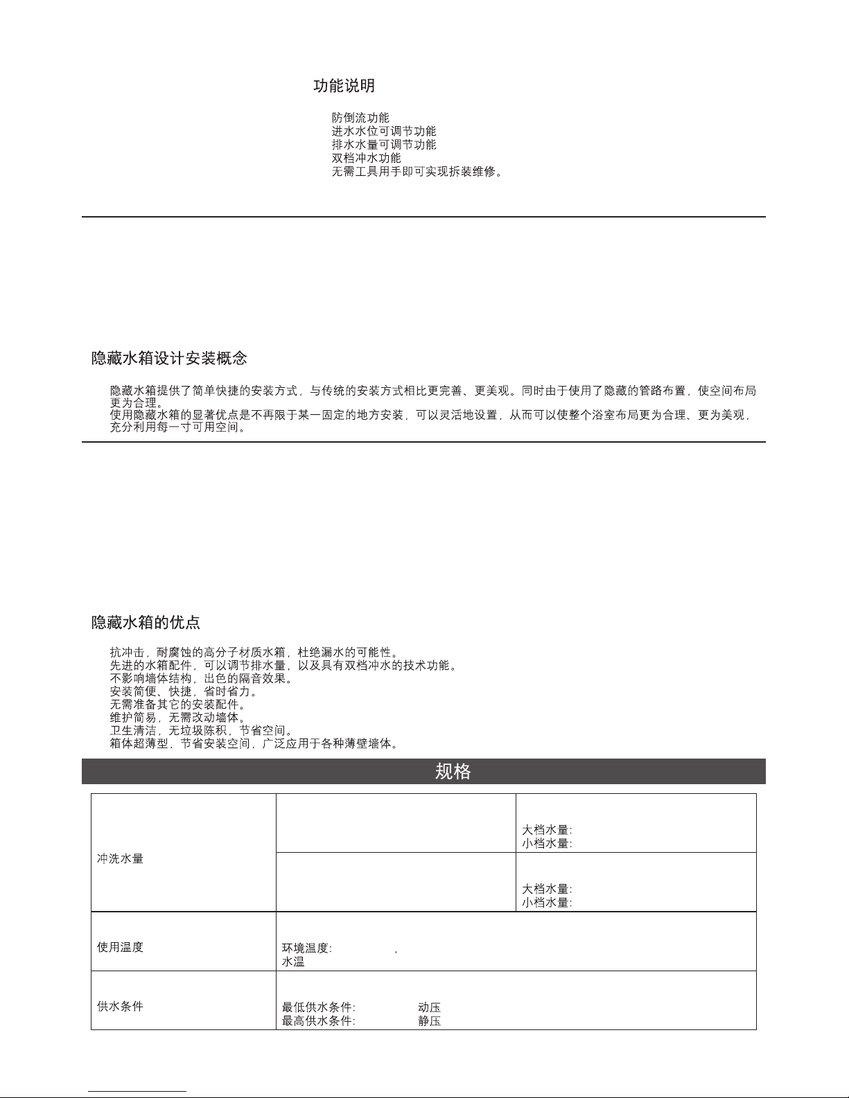
SPECIFICATIONS
Liter per flushing
Temperature
Environmental temperature: 1 ~55
Water temperature: 1 ~45
°C °C,
°C °C
°C °C
°C °C
1 ~55
1 ~45
Full flushing volume:
Half flushing volume:
6L
3L
6L
3L
K-4179T
K-10611T
K-4178T
Full flushing volume: 4.5L
Half flushing volume: 3L
4.5L
3L
!
!
!
!
!
Function Explanation
!
!
!
!
!
Anti flow-backwards
Adjustment of inlet water level
Adjustment of flushing volume
Single/double gear
Assemble, disassemble and
maintenance can be done without
tools.
flushing
Water Supply
Min water supply: 0.02MPa (dynamic pressure)
Max
water supply: 0.74MPa (static pressure)
0.02MPa ( )
0.74MPa ( )
1263048-T01-C
Page 3

RECOMMENDES TOOLS AND MATERIALSRECOMMENDES TOOLS AND MATERIALS
!
!
!
!
!
!
!
!
!
!
!
!
!
Open end/adjustable wrenches
Allen wrench
Knife
File
Hacksaw
Masonry
Level
Screw driver
Insulation tape
Tape measure
Seal tape
Bushing
Lubricant
!
!
!
!
!
!
!
!
!
!
!
!
!
/
-3-
ROUGHING-IN
UNIT: mm
Reference Value
K-4179T/K-4178T
478 3
88 2
438 3
681 4
269 5
35 2
100 3
205 3
1048 4
1066 4
1098 4
Finished floor
90~142
18~62
45~95
90 0.5
230 3
180 3
52~230
Height Suggested/ 1150
K-10611T
478 3
88 2
440 3
333 2
Finished floor
722~792
(235~305)
604~674
60 1
Height to floor is decided by bowl
18~62
1263048-T01-C
Page 4
K-4177T
K-75890T
K-8857T
K-75891T
K-20341T
215 1
225 1
150 1
160 1
150 1
160 1
160 1
215 1
225 1
225 1
Kohler reserves the right to change marked dimensions without prior notice.
-4-
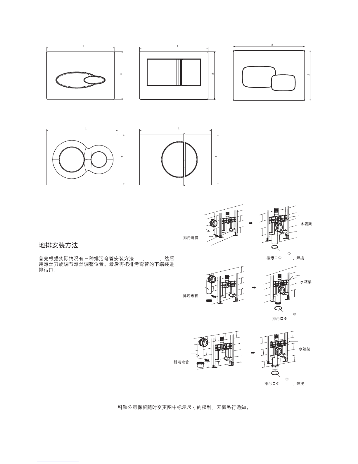
Floor Discharge Installation Method
Three discharge pipe installation methods based on actual
situation: A, B, C, adjust position by screw driver. Snap
discharge pipe lower end into discharge port.
ABC
B
C
A
Discharge
Elbow
Discharge
Elbow
Discharge
Elbow
Water Tank
Bracket
Water Tank
Bracket
Water Tank
Bracket
Drain outlet 90mm, welding
90mm
Drain outlet 110mm
110mm
Drain outlet 110mm, welding
110mm
1263048-T01-C
Page 5
-5-
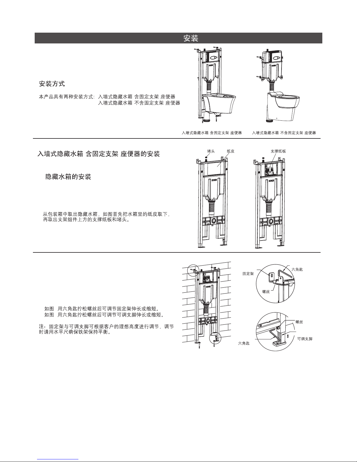
INSTALLATION
Way of Installation
There are two ways to install this product: in-wall tank with
frame & in-wall tank without frame
()
()
In-wall Tank Without Frame
()
In-wall Tank With Frame
()
Installation For In-wall Tank With Frame
A. Installation of In-wall Tank
()
A.
1. Remove in-wall tank from packing box. Remove paper
board inside water tank first as shown. Then remove board
and plug above bracket assembly.
1.
Plug Paper Board Board
2. Loose hex-head screw and adjust mounting bracket height
as shown in Fig A.
Loose hex-head screw and adjust supporting feet height as
shown in Fig B.
mounting bracket and supporting feet shall be adjusted
per customer ideal height. Use leveler to ensure the balance
of steel bracket.
Note:
2. A
B
Screw
Screw
Hex-head
Wrench
Medium
Allen Key
Adjustable
Bracket
Mounting
Bracket
A
B
1263048-T01-C
Page 6
-6-
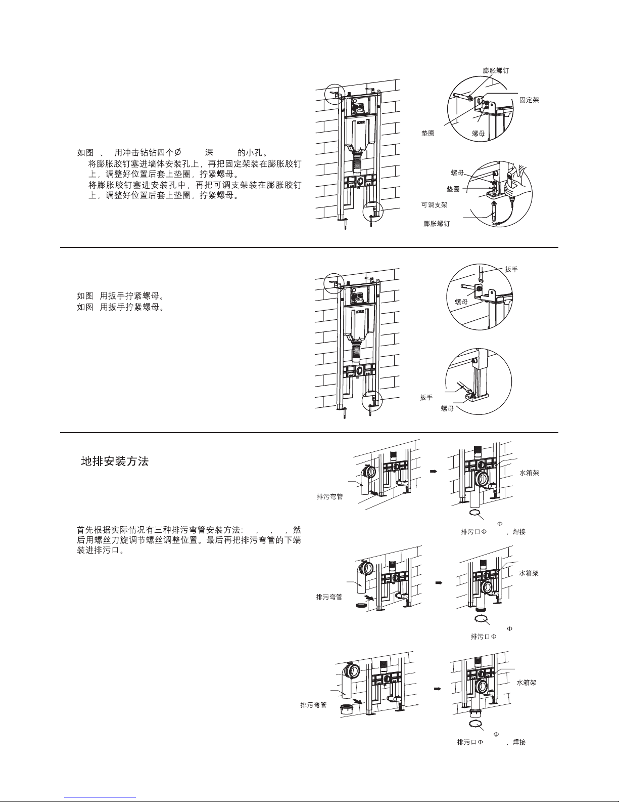
3. Drill four holes with diameter of 10mm and depth of 80mm
with churn drilling as shown.
A. Fill the bulge nail into the instruction hole on the wall, fix
the fixing frame to the bulge nail, adjust the gasket and
tighten the nut.
B. Fill the bulge nail into the instruction hole, fix the
adjustable bracket to the bulge nail, adjust the gasket
and tighten the nut.
3. A B 10mm 80mm
A.
B.
Adjustable Bracket
Mounting
Bracket
A
B
Bulge Screw
Bulge Screw
Gasket
Gasket
Nut
Nut
4. Tighten the nut with the wrench as shown in illustration A.
Tighten the nut with the wrench as shown in illustration B.
4. A
B
A
B
Nut
Nut
Wrench
Wrench
B. Floor Discharge Installation Method
B.
1. Three discharge pipe installation methods based on actual
situation: A, B, C, adjust position by screw driver. Snap
discharge pipe lower end into discharge port.
1. ABC
B
C
A
Discharge
Elbow
Discharge
Elbow
Discharge
Elbow
Water Tank
Bracket
Water Tank
Bracket
Water Tank
Bracket
Drain outlet 90mm, welding
90mm
Drain outlet 110mm
110mm
Drain outlet 110mm, welding
110mm
1263048-T01-C
Page 7

-7-
2. Tighten the long screw into the holes of the tank bracket
and cover the drainage hole with the big cap, cover the
inlet hole with the small cap.
2.
Inlet Hole
Drainage Hole
Big Cap
Tank Bracket
Small Cap
Long Screw
3. Connect tap water braided tube on the top of water tank for
water supply as shown.
Note: 1. Ensure water tank internal valve is OFF.
2. Suggestion: connect a temporary rubber or plastic
hose on valve, flush water supply pipeline. Ensure
water is clean, no residual sand stone or fouling
inside pipeline.
3.
1.
2.
Water Pipe
Connecting Pipe
Mask
Screw
Water Tank
Protective Cover
4. Install rectangle cover
1) Install the rectangular shield in the block screen of the
tank, and tighten the screw to fix mask to the tank.
4.
1)
C. Installation of P-trap
C.
1. Insert drainage pipe with inner diameter 110mm into
drain elbow and weld.
1. 110mm
Water Tank Bracket
Drainage Pipe
1263048-T01-C
Page 8

-8-
2. Tighten the long screw into the holes of the tank bracket
and cover the drainage hole with the big cap, cover the
inlet hole with the small cap.
2.
Long Screw
Inlet Hole
Drainage Hole
Big Cap
Tank Bracket
Small Cap
3.
3. When finishing the brickwork of the wall, take out the big
and small caps, and eliminate unwanted mask with a sharp
knife.
Big Cap
Small Cap
D. Installation of Toilet
D.
1. Install the inlet pipe to the lavatory as shown, and mark on
the pipes at the back side of the tank with a ruler and a
pencil, and reserve appropriate space according to the
distance from the back of the tank to the inlet hole on the
wall.
1.
Inlet Pipe
Drainage Pipe
Mask
2.
Inlet Pipe
Reserved Space
Drainage Pipe
2. Eliminate unwanted part of the inlet pipe according to the
marks of reserved space ,and rasp a smooth surface with
files.
1263048-T01-C
Page 9

-9-
3. Install the big and small leak-proof gaskets on inlet pipe
and outlet pipe ,then install it to corresponding pipes on the
toilet tank.
3.
4. 48mm-58mm of the long screw shall be reserved outside
the wall as shown in the illustration. if the long screw
outside the wall is not long enough or much longer than
that needed, it should be adjusted with screwdriver or by
hand. Then apply lubricant to drainage pipe and limber
pipe to ensure a smooth installation.
4. 48mm-58mm
48mm-58mm
Long Screw
Lubricant
Small Leak-proof Gasket
Inlet Pipe
Drainage Pipe
Big Leak-proof Gasket
5. Install the toilet as shown in the illustration, and use a spirit
level to ensure the lavatory to remain level.
5.
Spirit Level
Gasket
Long Screw
Reversed Lock
Hexagonal Nut
Decoration Cap
6. Install the reserved lock, gasket, hexagonal nut and
decoration cap onto long screw according to the order
shown in the illustration.
Please refer to the installation instructions of toilet.Note:
6.
1263048-T01-C
Page 10

-10-
1. Push slot A and slot B of the break water board forward
and then insert into the detent.
When installing the break water board, please make
sure the slot is align with the detent.
After the break water board is installed, please make
sure hinge ears are on the bottom.
Tip 1:
Tip 2:
1. A B
1
2
Mask
Break Water Board
Slot A
A
Slot B
B
Hinge Ear
Detent
E. Faceplate Installation
E.
2. When tighten four locknuts on supporting board, adjust to
"OPEN" mark as shown.
2. OPEN
Supporting Board
Locknut
Fixing Lock
Supporting Board
Locknut
3. Tighten four screws to "LOCK" mark after nstalling
supporting board as shown.
3. LOCK
4. Tighten the long screws to the bolt through the hole.
the long screw should be vertical to the wall.Note:
4.
Bracket
Screw
Long Screw
1263048-T01-C
Page 11

-11-
5. Install the faceplate as shown in the illustration. Put the
lock on the faceplate directly on the reversed lock on
supporting board, then push the faceplate and lock it. The
installation shall begin from bottom to top.
5.
Faceplate
Faceplate
Supporting
Board
Lock
6. It is ready to use when connected to water supply after
installation.
6.
Half Flush Button
Full Flush
Button
Installation For In-wall Tank Without Frame
A. Installation of In-wall Tank
A.
1. Remove in-wall tank from packing box. Remove paper
board inside water tank first as shown. Then remove board
and plug above bracket assembly.
1.
Plug Paper Board
Board
1263048-T01-C
Page 12

-12-
2. Make sure of h according to dimensions of bowl and then
locate the installation hole of fixing bracket. Mark on the
wall for appropriate position for fixing bracket, and drill four
holes with diameter of 10mm and depth of 80mm with
churn drilling as shown in illustration, and fill in the holes
with bulge screw and tighten the screw to set the fixing
bracket.
Note: Ensure the fixing bracket to remain level.
2. h
10mm 80mm
O
Fixing Bracket
Bulge Screw
Gasket
Spring
Nut
h
3. Put the tank onto the fixing bracket as shown in the right
figure and adjust the tank to level . Then tighten screws
with hex-head key. Note: it is a must to keep the tank level.
Connect the inlet hose with tank inlet pipe.
Note: 1. Ensure water tank internal valve is OFF.
2. Suggestion: connect a temporary rubber or plastic
hose on valve, flush water supply pipeline. Ensure
water is clean, no residual sand stone or fouling
inside pipeline.
3.
1.
2.
Water Pipe
Screw
Level
Tank
Tighten
Loosen
Medium
Allen Key
Connecting Pipe
Mask
Screw
Water Tank
Protective Cover
4. Install the mask in the block screen of the tank, and
tighten the screw to fix the mask to the tank.
4.
5. Insert the inlet pipe and drainage pipe into the bowl, and
then adjust the syphon and drainage pipe to a proper
position to be fixed into the bowl. Make sure of the
positions of syphon and discharge elbow and then remove
the bowl.
5.
Inlet Pipe
Syphon
Discharge Elbow Drainage Pipe
1263048-T01-C
Page 13

-13-
7. Fix faceplate according to step E and then it is ready for
use.
7. E
Half Flush Button
Full Flush Button
Finished Installation Illustration
Sharp Knife
Mask
6. When finishing the brickwork, eliminate unwanted part of
the mask, the drainage pipe and the inlet pipe.
6.
Inlet Pipe
Drainage Pipe
REMOVE AND MAINTENANCE OF THE OUTLET VALVEREMOVE AND MAINTENANCE OF THE OUTLET VALVE
1.
1. Hold the faceplate with both hands and push upward to
take down the faceplate.
Faceplate
Faceplate
1263048-T01-C
Page 14

-14-
2.
2. Loosen the long screws as shown.
Supporting Board
3. Tighten the locknut to the marked position of OPEN to
take out the supporting board.
""
3. OPEN
Locknut
Supporting Board
4. Take out the supporting board as shown.
4.
5. Take out the break water board.
5.
Supporting Board
Mask
Break Water Board
Slot A
A
Slot B
B
Detent
6. Take out the pole lock and the reversed lock as shown.
6.
Pole Lock
Reversed Lock
1263048-T01-C
Page 15

-15-
7. Hold the top of the bracket, and unplug the locknut by
pulling the bracket.
7.
Bracket
8. Turn on/off the water supply
Turn on /off the water supply by turning the valve.
8.
9. Take out the bracket as shown.
9.
Valve
On
Off
Bracket
10. Loosen the filter nut as shown, and then take out the inlet
valve.
10.
Nut
Filter
Loosen
Tighten
11. Loosen the filter nut as shown and take out the inlet valve
to clean or adjust.
11.
Inlet Valve
1263048-T01-C
Page 16

12. Hold the upside of the fixing lock, and take it out as
shown.
12.
Fixing Lock
Fixing Lock
13. Pull discharge valve along the arrow direction as shown
to remove discharge valve.
13.
Outlet Valve
14. Remove discharge valve as shown and then take valve
out for cleaning or adjusting.
14.
Outlet Valve
-16-
A. Wash Filtration Net
Close corner valve first, then loosen and take out the
tighten nut, and wash the waste on filtration net with clean
water. then reset the tighten nut to the original position.
A.
Filtration Net
Filter
Loosen
Tighten
Locknut
1263048-T01-C
Page 17

-17-
B.
(1)
(2)
Floating Box
Drainage valve
Adjustment Switch
B. Adjust Drainage Valve
Drainage volume and overflow level of the tank can be
adjusted by drainage valve:1) heavy drainage adjustment:
open adjustment switch to open the small hole. 2) slight
drainage adjustment: adjust the height of floating box and
the water level of slight drainage will be at the bottom of
the floating box.
C.
C. Adjust Inlet Valve
Hoist and reduce the water level in the tank by adjusting
the control pole. Turn the control pole counterclockwise to
lower down the floating box and reduce the water level of
the tank .turn the control pole clockwise to hoist the
floating box and increase the water level in the tank.
Control Pole
Inlet Valve
Floating Box
TROUBLE SHOOTING PROCEDURESTROUBLE SHOOTING PROCEDURES
No water fills in via inlet
valve
The inlet valve is closed. Open inlet valve.
Floating box of inlet valve is blocked by other parts.
Floating box of inlet valve is block by waste. Wash the floating box with clean water.
No drainage when
pressing the heavy and
slight drainage button
Too high or too low water
level
Leak of the toilet and
squat
Toilet does not flush
Toilet does not flush
completely
Symptoms
Probable Causes
Recommended Action
The pole and the reversed lock are not connected.
Reinstall the reversed lock onto the pole of
the outlet valve.
The floating box of the inlet valve is not properly
adjusted.
Readjust the water level.
The floating box of the inlet valve is blocked by
wastes, so the water is leaked from the overflow
pipe.
A. No water supply.
B. The water supply stop is closed.
Readjust the position of other parts to avoid
contacting the floating box when it is
functioning.
A. Wait for restoration of water supply.
B. Open the water supply stop.
Readjust the position of other parts to avoid
contacting the floating box when it is
functioning.
The rubber gasket is blocked by wastes.
Filter screen is clogged.
Take out the outlet valve and clean the
wastes.
Refer to wash filtration net.
The adjustable board and the long screw are
wrongly installed.
Reinstall the long screw.
1263048-T01-C
Page 18

-18-
A.
B.
A.
B.
1263048-T01-C
 Loading...