


1285740-2A-B 1
BEFORE YOU BEGIN
All information is based on the latest product information available at the time of publication. Kohler Co. reserves
the right to make changes in product characteristics, packaging, or availability at any time without notice.
Please leave these instructions for the consumer. They contain important information.
NOTES:
1. Flush the water supply pipes thoroughly to remove debris.
2. If possible, install this faucet before installing the lavatory.
3. Inspect the supply tubing for damage and leakage. Replace and maintain as necessary.
4. Observe local plumbing codes.
5. Shut off the water supplies to the fitting.
HANDLE OPERATION
Lift handle gently. Turn clockwise for hot water, turn counter-colckwise for cold water.
1285740-2A-B 4
INSTALLATION INSTRUCTIONS
74013T-4E2 Single Lever Lavatory Faucet
74026T-4E2 Single Lever Tall Lavatory Faucet
74013T-4E2 Single Lever Lavatory Faucet
74026T-4E2 Single Lever Tall Lavatory Faucet
TAU TTAU T
ROUGH-IN DIMENSIONS
SERVICE PARTS
**Color code must be specified when ordering.
74026T-4E2
Ø36.5
Ø54
102
108
Ø31.75
20°
120
202
270
420
40 Max.
Ø33~Ø36
G1/2˝
1242786**
1209778**
1209777
1292054
1209774
3008523
74013T-4E2:836549
1209787
1281228
1281236
833438
1121328**
1080817
880406
880008**
880037
74026T-4E2:836664
1226072**
870817 74013T-4E2:1280659
74026T-4E2:1280658
74013T-4E2:1024405
74026T-4E2:880096
1228834
1285740-2A-B 2
1285740-2A-B 3
INSTALLATION CHECKOUT
Ensure that all connections are tight. Ensure that the
handle is in the off position. Turn on the drain and
main water supply, and check for leaks. Repair as
needed.
Remove the aerator(22) by coin. Turn on the faucet.
Run hot and cold water through the spout for about
one minute to remove any debris. Remove debris from
the aerator. Shut off the faucet and reinstall the
aerator.
CLEANING INSTRUCTIONS
All Finishes: Clean the finish with mild soap and warm water. Wipe entire surface completely dry with clean soft
cloth. Many cleaners may contain chemicals, such as ammonia, chlorine, toilet cleaner etc, which could adversely
affect the finish and are not recommended for cleaning.
Do not use abrasive cleaners or solvents on Kohler faucets and fittings.
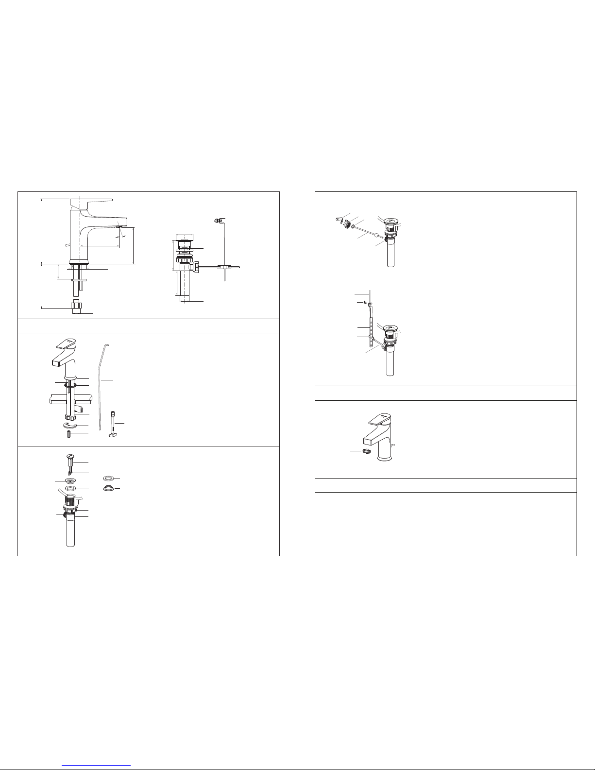
INSTALLATION
How to Install the Spout
Install the mounting stud(2) onto the faucet body
base(3). Insert lift rod(5) to the hole at the rear of the
body. Slide the washer(4) over the flexible hoses(1),
lift rod and mounting stud, and into the groove at the
bottom of the faucet body.
Insert the faucet assembly into the lavatory hole.
Position the faucet. From underside of the lavatory,
place the bracket(6, Rubber washer is on the top)
onto the mounting stud, and tighten the nut(7) by
tool(8) to secure the faucet.
Attach the hoses to water supplies. When facing front
of the faucet , the left hose connects to hot water, the
right hose with "COLD" label connects to cold water.
How to Install the Drain
Remove stopper(12), flange(9) and washer(10) from
drain body(11). Insert drain body kit into the lavatory
from underside, and make sure the drain lever
hole(15) facing to the back of the lavatory. Screw the
flange with washer into the drain body. Tighten the
locknut(14) by hand from the underside of the fixture.
NOTE: If needed, apply a ring of plumbers putty
around the underside of the drain flange(9), instead of
using washer(10).
Place stopper(12) into drain body aligning the flat side
of stopper hole(13) with the drain lever hole.
Remove the retaining nut(17). Fit the plastic
washer(18) and retaining nut onto the ball lever(19).
Insert the ball lever assembly into the drain lever hole
and through the stopper hole. Tighten the retaining
nut.
Be sure that the ball lever(19) points to the back of the
lavatory, tighten the locknut(14) on the drain body by
wrench.
NOTE: Do not reposition the drain if plumbers putty
applied after the locknut is tightened, or you may
break the putty seal. Wipe away excess plumbers
putty.
Assemble thumb screw(20) to link(21), and link onto
ball lever(19) with ‘V’-clip(16). Slide lift rod(5) into the
hole in link.
Push the ball lever down into the open position, and
adjust the lift rod. Tighten thumb screw(20).
74013T-4E2
Ø36.5
Ø54
102
108
Ø31.75
157
100
89
18°
40 Max.
Ø33~Ø36
G1/2˝
430
3
5
2
1
4
6
7
22
8
12
13
10
10
9
9
11
14
15
18
15
19
17
16
5
19
21
16
20
 Loading...