

Page 1

Installation and Homeowners Guide
Veil Bathroom Heater S600G
S600G
K-21463T-G-0(Aircare)
K-21463T-XG-0
K-21465T-G-0
(Cloud)
KOHLER CHINA INVESTMENT CO., LTD NO.158, JIANG CHANG SAN ROAD,
1373009-T01-A
JING'AN DISTRICT, SHANGHAI, PRC POST CODE: 200436
( ) 158 200436
Page 2
BEFORE YOU BEGIN
Please read these instructions carefully to familiarize
!
yourself with the required tools, materials, and installation
sequences. Follow the sections that pertain to your
particular installation. This will help you avoid costly
mistakes. In addition to proper installation, read all
operation and safety instructions.
All information in these instructions is based upon the
!
latest product information available at the time of
publication. Kohler China reserves the right to make
changes in product characteristics, packaging, or
availability at any time without notice.
These instructions contain important care, cleaning, and
!
warranty information -
consumer
This product complies with GB 4706.1-2005, GB4706.23-
!
.
please leave instructions for the
2007, GB 4706.27-2008, GB7000.1, GB7000.202 and
GB/T17743.
WARNING: Risk of electrical shock.
A licensed
electrician should make all electrical connections.
WARNING: Risk of electrical shock.
Connect only to
a circuit protected by a typical two-pole circuit breaker.
WARNING: Risk of electrical shock.
Disconnect
power before servicing.
!
,
!
!
!
GB 4706.1-2005 GB4706.23-2007 GB
4706.27-2008 GB7000.1 GB7000.202 GB/T17743
-
RECOMMENDED TOOLS AND MATERIALSRECOMMENDED TOOLS AND MATERIALS
!
Tape measure
!
Level
!
Screw driver
!
Connection wire
!
Wire cutter
!
Insulation tape
!
Bushing
!
Percussion Drill
!
Pen Knife
!
Wrench
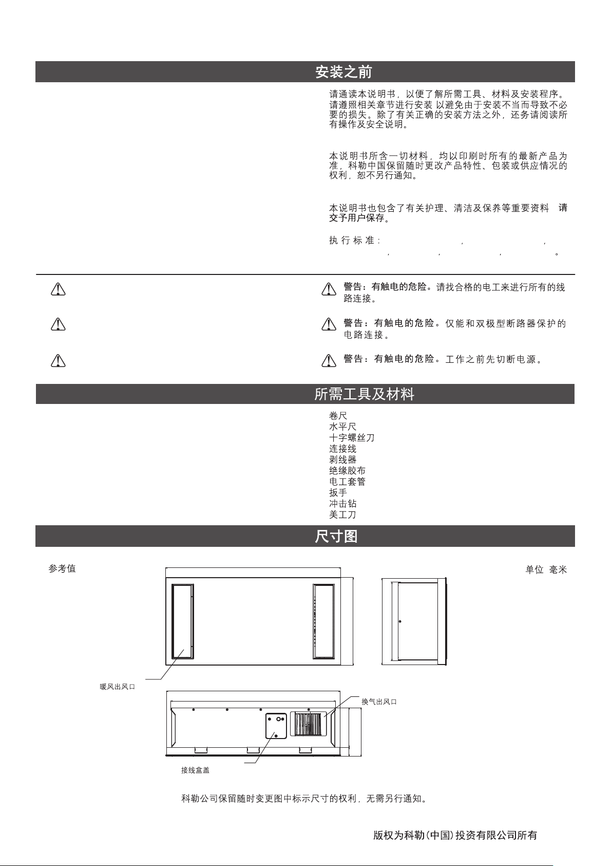
ROUGHING-IN
Reference Value
Hot Air Outlet
600
595
564
!
!
!
!
!
!
!
!
!
!
Unit: mm
:
269
295
300
Ventilation Outlet
1373009-T01-A
136
167
Junction Box Cover
31
Kohler reserves the right to change marked dimensions without prior notice.
-1-
©©Copyright Kohler China Investment Co., Ltd. 2018
2018
Page 3
SPECIFICATIONS
Model
Voltage/Frequency
Rated Input Power
Heater Power
Fan Power
Dry Clothing Power
Ventilation Power
Air-care Power
Lighting Power
Ventilation Volume
Ventilation Noise
K-21463T-G-0/K-21463T-XG-0/
K-21465T-G-0
220V~/50Hz 220V~/50Hz
2750W 2750W
2731W 2731W
30W 30W
2600W(Hot)/60W(Cool)
33W 33W
31W(K-21463T-G-0/K-21463T-XG-0 )Only
19W 2 (108pcs 0.2W) 19W 2 (108 0.2W)
3
m /min
3.3 3.3m /min
43dB 43dB
IPX2 (Bathroom Heater) IPX2 ( )
Ingress Protection
IPX4 (Remote Control)
IP20 (LED)
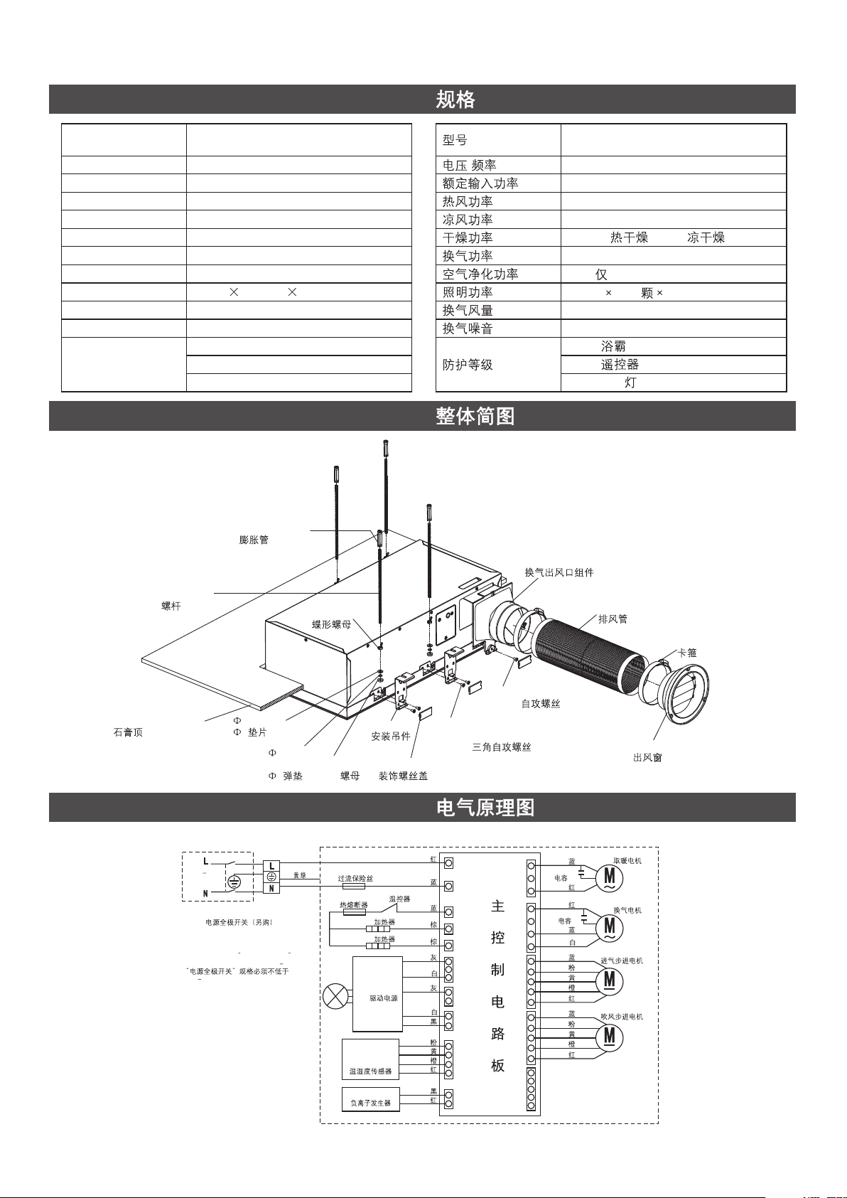
SIMPLIFIED DIAGRAM OF THE UNIT
Expansion Pipe
K-21463T-G-0/K-21463T-XG-0/
K-21465T-G-0
/
2600W( )/60W( )
31W( K-21463T-G-0/K-21463T-XG-0)
3
IPX4 ( )
IP20 (LED )
M6 Screw Rod
M6
Plasterboard Ceiling
WIRING DIAGRAM
K-21463T-G-0
220V
50Hz
ALL-POLE SWITCH (OPTIONAL)
THE RATE OF THE POWER SWITCH
MUST NOT BE LOWER THAN 250V 20A
250V 20A
6 Washer
6
Washer
M6 Butterfly Nut
M6
6 Spring
6
YELLOW/GREEN
/
Hanger
M6 Nut
M6
OVER CURRENT FUSE
THERMAL FUSE
HEATER 1 1
HEATER 2 2
LED POWER
LED
TEMPERATURE
AND HUMIDITY
SENSOR MODULE
ANION GENERATOR
BTP4*8 Triangular
Self Tapping Screw
BTP4*8
Decorative Screw Cover
RED
P1
BLUE
BLUE
GRAY
GRAY
PINK
RED
RED
P2
P3
P4
P5
CN4
CN14
CN11
CN12
CN5
THERMOSTAT
BROWN
BROWN
YELLOW
ORANGE
WHITE
WHITE
BLACK
BLACK
Ventilation Outlet Assy.
ST4.2*8 Self-tapping Screw
ST4.2*8
BLUE
CAPACITOR
MAIN CONTROL CIRCUIT BOARD
CN2
CN3
CN8
CN6
CN7
RED
RED
CAPACITOR
BLUE
WHITE
BLUE
PINK
YELLOW
ORANGE
RED
BLUE
PINK
YELLOW
ORANGE
RED
Air Exhaust Pipe
Clamp
Air Outlet Window
HOT MOTOR
VENT MOTOR
STEPPER MOTOR
STEPPER MOTOR
1373009-T01-A
-2-
Page 4
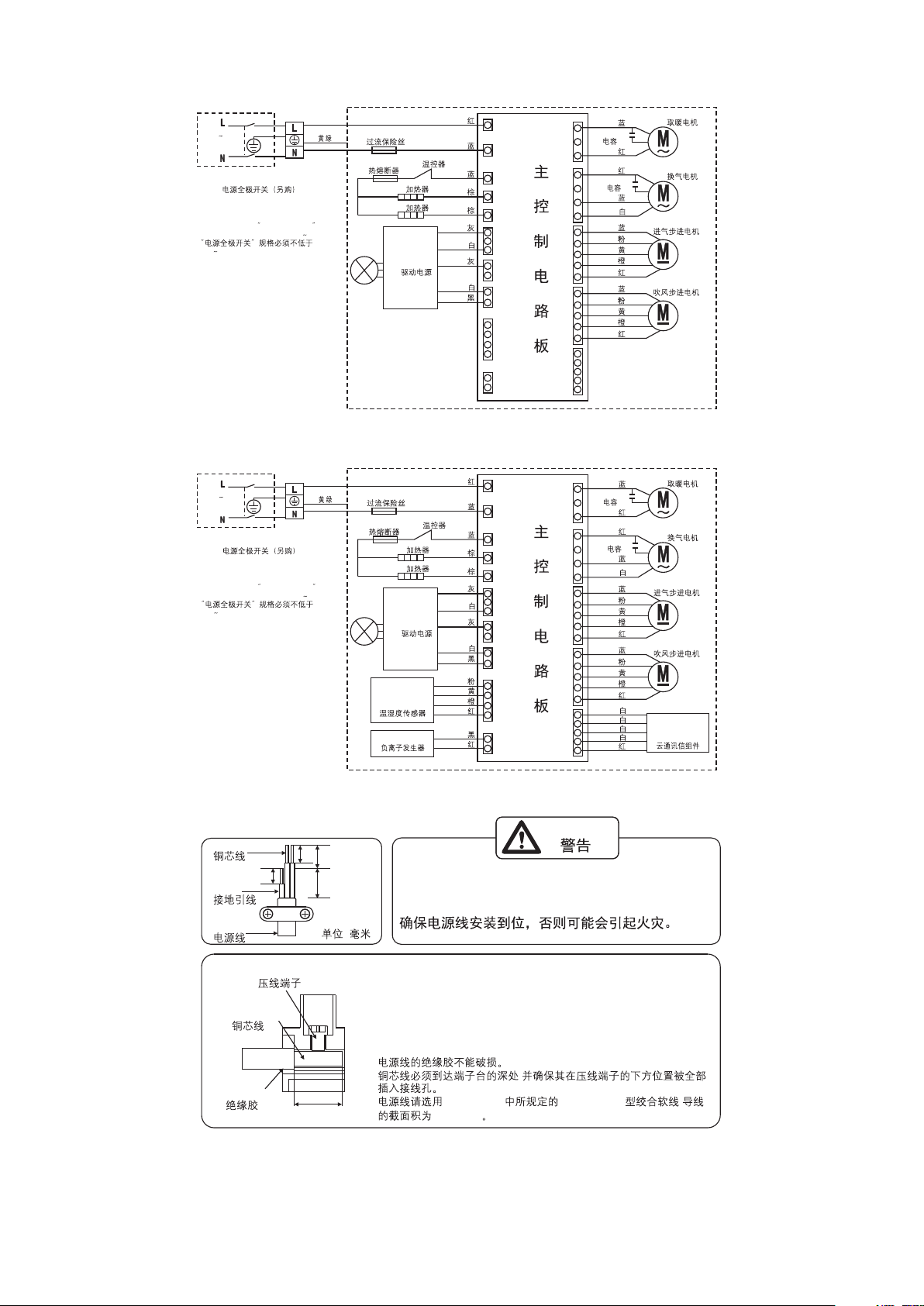
K-21465T-G-0
220V
50Hz
ALL-POLE SWITCH (OPTIONAL)
THE RATE OF THE POWER SWITCH
MUST NOT BE LOWER THAN 250V 20A
250V 20A
YELLOW/GREEN
K-21463T-XG-0
220V
50Hz
ALL-POLE SWITCH (OPTIONAL)
THE RATE OF THE POWER SWITCH
MUST NOT BE LOWER THAN 250V 20A
250V 20A
YELLOW/GREEN
OVER CURRENT FUSE
/
OVER CURRENT FUSE
/
THERMAL FUSE
HEATER 1 1
HEATER 2 2
LED POWER
LED
THERMAL FUSE
HEATER 1 1
HEATER 2 2
LED POWER
LED
TEMPERATURE
AND HUMIDITY
SENSOR MODULE
ANION GENERATOR
THERMOSTAT
BROWN
BROWN
THERMOSTAT
BROWN
BROWN
YELLOW
ORANGE
RED
BLUE
BLUE
GRAY
WHITE
GRAY
WHITE
BLACK
RED
BLUE
BLUE
GRAY
WHITE
GRAY
WHITE
BLACK
PINK
RED
BLACK
RED
P1
P2
P3
P4
P5
CN4
CN14
CN11
CN12
CN5
P1
P2
P3
P4
P5
CN4
CN14
CN11
CN12
CN5
MAIN CONTROL CIRCUIT BOARD
MAIN CONTROL CIRCUIT BOARD
CN2
CN3
CN8
CN6
CN7
CN2
CN3
CN8
CN6
CN7
BLUE
CAPACITOR
RED
RED
CAPACITOR
BLUE
WHITE
BLUE
PINK
YELLOW
ORANGE
RED
BLUE
PINK
YELLOW
ORANGE
RED
BLUE
CAPACITOR
RED
RED
CAPACITOR
BLUE
WHITE
BLUE
PINK
YELLOW
ORANGE
RED
BLUE
PINK
YELLOW
ORANGE
RED
WHITE
WHITE
WHITE
WHITE
RED
HOT MOTOR
VENT MOTOR
STEPPER MOTOR
STEPPER MOTOR
HOT MOTOR
VENT MOTOR
STEPPER MOTOR
STEPPER MOTOR
CLOUD
COMMUNICATION
ASSEMBLY
1373009-T01-A
Conductor
Earth
Power Cord
Terminal
Conductor
Insulation
WARNING
8
8
13 10
Make sure the power cord installed firmly,
otherwise it may catch fire.
(Unit: mm)
(: )
+
There's no risk of damage to the insulation of power cord.
+
Copper cord must be inserted into the pillar terminal hole, and make
sure all the cords under the terminal are inserted into the pillar
terminal completely.
Suggest using a power cord which with specification 60227 IEC 53
+
Model's powercord Specified in GB/T 5023.5 and with cross section
of 3X1.5mm .
+
+
8
+
2
,
GB/T 5023.5 60227 IEC 53 ,
3X1.5mm
2
-3-
Page 5
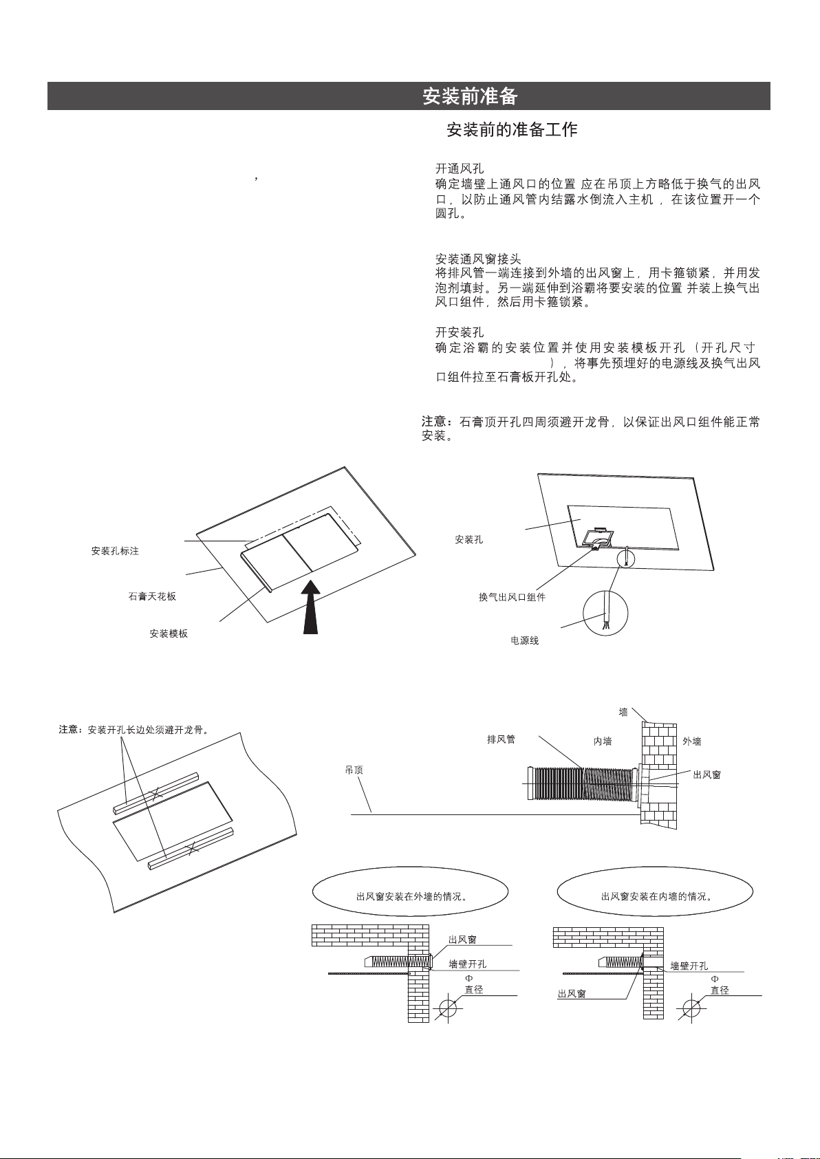
PREPARATIONS BEFORE INSTALLATION
A. Preparation before the installation A.
1. Open the hole of outlet window
Make sure that the outlet window s position (it should be
lower than the outlet of the bathroom heater to prevent the
water come back to the bathroom heater from the outlet
window), and open a round hole on the wall.
2. Outlet window installation
Sealing one end of the air exhaust pipe to the outlet
window on the wall with the clamp, and fix the other end to
ventilation outlet assembly with the clamp.
3. Make a Mounting Hole
Locate the position of the bathroom heater and make the
holes with the installation template (Hole Size 275 mm *
+5
575 mm ). Bring the power cords and ventilation outlet
0
+5
0
assembly to the hole edge on the plasterboard.
The keels should not be placed on the edges of the
Note:
installation holes to ensure that the ventilation outlet
assembly could be installed correctly.
Installation Hole Mark
1.
2.
3.
+5
275 mm * 575 mm
0
Installation Hole
(
)
,
+5
0
:
Plasterboard
Ceiling
Install Template
Please avoid the keels.Note:
Ceiling
Outer wall installing.
Ventilation
Outlet Assy.
Air Exhaust Pipe
Outlet Window
Hole on the Wall
120mm
120mm
Power cord
Inner Wall
Outlet Window
Wall
Outer Wall
Outlet Window
Inner wall installing.
Hole on the Wall
110mm
110mm
1373009-T01-A
-4-
Page 6

B. Take out the bathroom from package. B.
Bathromm Heater
C. Packing List C.
1367446
100 Air Outlet Window
100
1367447
100 Air Exhasut Pipe
100
Note: Initial Length: 140mm
Stretch Length: 2000mm
1285549
Clamp
2
1373399
Ventilation Outlet Assy. S600G
S600G
140mm
2000mm
1367441
Fixed Column Assy.
M6 Expansion Head
M6
10 Expansion Pipe
10
M6 Screw Rod
M6
1285553
Lock Assy. /
M6 Butterfly Nut
M6
6 Washer
6
6Spring Washer
6
M6 Nut
M6
305mm
BTP4 8 Triangular
Self Tapping Screw
BTP4 8
1373457
Heater Accessories Assy.
1373009-T01-A
Hanger
Triangular
Self-tapping Screw
BTP4*8
1367443
Remote Control Assy.
Remote Control
(Only K-21465T-G-0
( K-21465T-G-0)
-5-
Remote Control Base Assy.
Base
)
M4*25 Screw
*2
Cover
*2
6 Plastic
Expansion Pipe
6*2
Page 7

1373458
Wooden Bar
1373401
Installation Template
S600G
S600G
1367442
Remote Control Assy.
Remote Control
(Only K-21463T-G-0/
K-21463T-XG-0
( K-21463T-G-0/
K-21463T-XG-0)
Remote Control Base Assy.
Base
)
M4*25 Screw
*2
INSTALLATION
Caution before installation:
The installed product must be 200mm or above away from
!
curtains or other combustible materials.
The distance between the ceiling where the product is
!
mounted and the roof shall be 200mm or above.
Ensure that the gap between the product edge and the
!
wall is 300mm or above.
The power cord to the product shall have enough length
!
for the installation.
The distance between the product and the air outlet
!
window shall be 2000mm or lower.
Cut the screw rod(M6) to suit the distance between the
!
ceiling and the roof.
Wall
!
!
!
!
!
!
Air Outlet Window
Cover
2000mm
Under 2000mm
2000mm
*2
200mm
6 Plastic
Expansion Pipe
6*2
200mm
300mm
(M6)
Air Exhaust Pipe
Above 300mm
300mm
Above
300mm
300mm
1373009-T01-A
-6-
Page 8

1. Installing the Main Body Method 1 Plasterboard Ceiling.
1.
(1) Bend the installation template to 90 at the bending line.
°
Push the template to the marked location.
Installation Hole
Plasterboard
Ceiling
Ventilation
Outlet Assy.
Marked Hole
Install Template
(1) 90
M6
M6
Bending Line
Install Template
Cement Board
179
179
(2) Plug the M6 screw rod on the cerement board and
attach the hanger to the rod as the diagram shows. Fix
two wooden bars to the hanger with 8 ST 4.2*10
triangular screws.
M6 Butterfly Nut
M6
6 Washer
6
6 Spring Washer
6
M6 Nut
M6
Hanger Clinging to Plasterboard
(2) M6
M6
ST4.2*10
(8pcs)
1373009-T01-A
ST4.2*10 Triangular
Self Tapping Screw
ST4.2*10
Wooden Bar
Ventilation
Outlet Assy.
-7-
Page 9

(3) Demount five decorative screw covers. (3) 5pcs
Decorative Screw Cover
(4) Fix the power cord to the bathroom heater
(I) Remove the screw on the wiring cover plate.
(II) Open the wiring cover plate.
(III) Lift the terminal protection cover.
(IV) Loosen the screw fixing the power cord clip.
(V) Loosen the screw on the wiring terminal, insert the
power cord (not supplied) connected to the indoor
fixed line into the wiring terminal, tighten the wring
terminal screw.
(VI) Fix the power cord with power cord clips. (The
power cord clip must pin the insulation sheath of
power cord.)
(VII) Use the screw removed in step (I) to fix the wiring
cover plate again.
Junction Box Cover
ST2.9*7 Self-tapping Screws
ST2.9*7
(5) Push the bathroom heater to hole and install the
ventilation outlet assembly first with 1 ST 4.2*8 selftapping screw.
Plasterboard
Ceiling
Installation Hole
(4)
(I)
(II)
(III)
(IV)
(V)
()
(VI) (
)
(VII) (I)
Power Line
Wire Clamp
Terminal
(5) ,
ST4.2*8 (1pc)
Groove
Push-in
1373009-T01-A
Ventilation
Outlet Assy.
Ventilation Outlet
Assy. Hook
Ventilation Air Outlet
Panel Base
ST4.2*8 Self-tapping Screws
ST4.2*8
-8-
Page 10

(6) After the bathroom heater is fully inserted into the hole.
Fix the hanger with the heater by using 8 BTP 4*8
triangular self-tapping screws. Finally, put back the
decorative screw covers.
Plasterboard
(6)
BTP4*8
(8pcs) (
)
(5pcs) ( )
Panel Base
2. Installing the Main Body Method 2 Ceiling mounting has
not been installed.
(1) Positioning and installation of the suspenders
1) Mark the holes of screw rods on the cement board as
the figure shows.
Panel Base Clinging to Plasterboard
Decorative
Screw Cover
BTP4*8 Triangular
Self-tapping Screw
BTP4*8
Plasterboard
Ceiling
2.
(1)
1)
90
°
180
°
Install Template
Marked Hole
Cement Board
Marked Hole
Center Line
Marked Hole
1373009-T01-A
-9-
Page 11

2) Make the holes at the marked position. 2)
Cement Board
Suspender
(2) Demount five decorative screw covers. and install the
ventilation outlet assembly first with 1 ST 4.2*8 selftapping screw.
Decorative Screw Cover
(3) Fix the hangers to the heater with 8 BTP 4*8 self-
tapping screws. And put back the 5 pcs decorative
screw covers.
Hanger
BTP4*8 Triangular
Self Tapping Screw
BTP4*8 (4 )
(4) Hang the bathroom heater on the ceiling with the screw
rods and modify the levelness. Finally tightening the
screws.
(2) (5pcs)
ST4.2*8 (1pc)
ST4.2*8 Self-tapping Screws
ST4.2*8 (1 )
(3) BTP4*8 (8pcs), ,
(5pcs)
Decorative Screw Cover
(4) ,
M6 Butterfly Nut
M6
6 Washer
6
6 Spring Washer
6
M6 Nut
M6
(5) Fix the pipe and ventilation outlet assembly with the
clamp.
Ventilation Outlet Assy.
Clamp
(5)
Air Exhaust Pipe
Indoors
Outdoors
Slant Taper
1
()
~
100150
1373009-T01-A
-10-
Page 12

INSTALLATION OF REMOTE CONTROLLER HOLDERINSTALLATION OF REMOTE CONTROLLER HOLDER
NOTE:
If the wall for installation is made of special material
(such as wood board, density board and etc.), suitable fixing
methods shall be adopted.
NOTE:
The place to install the remote controller shall not be
easily splashed by water.
Choose a mounting location for the remote holder.
Drilling two holes with depth larger than 45mm on the wall by
drill with a diameter of 6mm in accordance with the position of
screw holes on the remote control holder. Installing the
expansion tube into the holes.
Placing the installation holder on the fixing hole.
Fixing the holder with screws and install it.
Installing the screw covers on the screws.
Placing the remote controller on the holder.
Remote Control
6mm
45mm
Base
Screw
INSTALLATION OF COIN BATTERYINSTALLATION OF COIN BATTERY
Please follow the installation diagram.
Head
Bottom
Bottom
Head
USER'S GUIDE
A. Before Using
!
Before using the remote control, please take off the
battery insulating strip.
Before using the remote controller, please wait for 5
!
seconds after the power source is connected.
Cover
Coin Battery (CR2430)
A.
!
!
Expansion Tube
Head
Bottom
5
1373009-T01-A
Battery Insulating Strip
-11-
Page 13

B. Paring
!
Please press "Light" and "Light Off" together within 3
B.
!
minutes after connecting to power source. If "Beep, Beep,
Beep" can be heard and the LED light is on, it means
paring is successful.
C. Button Function C.
3
LED
DOWN : Timer Down/Temperature Down.
UP : Timer Up/Temperature ON.
HEATER : Turn on the heater mode
FAN : Turn on the fan mode
DRY : Turn on the hot /cool dry clothes mode
VENTILATION : Turn on the ventilation/long time vent mode
AIR FLOW : Set the air flow swing or fixed
AIR-CARE : Turn on the air-care mode
LIGHT : Lighting on and off/chang the light color
Light Off :
STOP : Stop certain function
Turning off the light.
D. Display Information D.
Current
/
/
24
/
()
1373009-T01-A
Set
Hour
Minute
Celsius
Humidity
HEATER
FAN
HOT DRY
COOL DRY
24H VENTILATION 24
VENTILATION
AIR-CARE
AIR FLOW FIXED
SWING MODE
-12-
Page 14

E. Activated mode
During the standby mode, press any button to the
!
activated mode
display room temperature and humidity, K-21465T-G-0
will display "00:00". Display will be turned off if not any
further action is taken with 10 seconds.
During the working mode,
!
display the room temperature and humidity. Display will
be turned off after the countdown finish.
!
Press the function button, the "beep will be heard.
, K-21463T-G-0/K-21463T-XG-0 will
K-21463T-G-0/K-21463T-XG-0
"
E.
!
!
!
K-21463T-G-0/K-21463T-XG-0
K-21465T-G-0 "00:00"
XG-0
10
K-21463T-G-0/K-21463T-
F. Time setting
!
Setting time could be changed during the "HEATER",
"
"FAN , "DRY", "VENTILATION" and "AIR-CARE" mode.
!
Setting time will be changed back to the default after each
use.
!
"HEATER": the default time is 3 hours, minimum time is
30 minutes, and maximum time is 6 hours.
!
If press "Stop" when the heater is working, the heater will
continue to work for next 30 seconds to protect the
machine and the remote control will show the count down.
!
"FAN": the default time is 3 hours, minimum time is 30
minutes, and maximum time is 6 hours.
!
!
!
!
!
"
"DRY : the default time is 3 hours, minimum time is 30
minutes, and maximum time is 6 hours.
If press "Stop" when hot dry is working, the heater will
continue to work for next 30 seconds to protect the
machine and the remote control will show the count down.
"VENTILATION": the default time is 3 hours, minimum
time is 30 minutes, and maximum time is 6 hours.
"AIR-CARE": the default time is 3 hours, minimum time is
30 minutes, and maximum time is 6 hours.
"24H VENTILATION": the default time is 6 hours, the
setting time cannot be changed.
G. Temperature Setting
Press "Heater" after the remote control is activated, and
!
the screen will show temperature setting. Pressing "+" or
"-" can increase or decrease the heating temperature.
Pressing "Heater" again within 10 seconds will turn to time
set.
"Heater": Default temperature is 40 C, maximum
!
temperature is 40 C while the minimum is 30 C.
°°
°
F.
!
!
!
6
!
!
6
!
!
!
!
!
/330
6
30
6
6
24 24
G.
!
40 C + -
°
!
30 C
°
+-
330
30
330
330
330
10
40 C 40 C
°°
1373009-T01-A
-13-
Page 15

TROUBLESHOOTING
Problem Diagnosis
Bathroom Heater does not
work.
The remote controller
does not display.
The remote controller
does not work.
A "Beep" alarm is on when
turn on "Heater",
"Ventilation", "Air-Care"
and "Cloth Dry".
A. A power failure occurred.
B. The power cord is disconnected.
C. Circuit breaker is in the "Off" position.
A. The battery has been used up.
B. The polarity of battery was installed inversely.
C. No wake-up.
A. No pairing with the bathroom heater.
B. The remote controller is used in an
inappropriate position or angle.
C. Low battery.
A. Dust filter need be cleaned.
Solution
A. Wait until the power is restored.
B. Connect the power cord into the junction box
of bathroom heater.
C. Turn on the power at the breaker.
A. Please replace the battery.
B. Please install the battery correctly.
C. Press any key to wake-up.
A. Make the pairing.
B. Change the using position or angle to make
the controller towards the bathroom heater.
C. Change the battery.
A. Clean the filter or press the "+" for 2 seconds
in the Activated Mode.
A.
B.
C.
A.
B.
C.
A.
B.
C.
A.
CARE & CLEAN
1. Shut off the power source, and turn around the wind swing
assembly manually.
A.
B.
C.
A.
B.
C.
A.
B.
C.
A. + 2
1.
Wind Swing Assy.
1373009-T01-A
-14-
Page 16

2. Hold the two ends of the filter, and take it off by pulling the
assembly.
2.
Holding Here
3. After the filter is cleaned, put it back to the wind swing
assembly, on which there is an arrow symbol. Please make
sure that the printed point is well matched with the mark to
install the filter correctly. Finally, turn on the power and the
wind swing assembly will restore automatically in 5
seconds.
Filter
Filter
3.
(
)5
Filter Printed Point
Filter Mark
IMPORTANT CONSUMER INFORMATION
1. When AC power unit is connected to 220V AC power
supply, corresponding protective measures should be
taken.
2. Please confirm no water penetration at the connection area
of AC wire, and the connection area is not easy to be
affected by damp.
3. The head AC power supply must be protected with
appropriate fuse.
4. Please confirm the AC power supply should be shut off
before maintaining the products with AC power related.
5. All electrical connection must be compliance with related
regulation and codes.
6. All installation staff should be well familiar with installation
instruction.
1. 220V
2.
3.
4.
5.
6.
Notice: Troubleshooting needs to be done by
professional of KOHLER CHINA. Users are not suggested
to do this without help. Please remember that the
checking and repairs done by users themselves could
easily cause damage to the machine or cause physical
harm to the person.
1373009-T01-A
-15-
 Loading...