

Page 1

Installation and Homeowners Guide
Underscore Bathroom Heater S300
S300
K-77316T-C-MZ
(Air-care)
KOHLER CHINA INVESTMENT CO., LTD NO.158, JIANG CHANG SAN ROAD,
JING'AN DISTRICT, SHANGHAI, PRC POST CODE: 200436
( ) 158 200436
1325978-T01-A
Page 2

-1-
BEFORE YOU BEGIN
©©Copyright Kohler China Investment Co., Ltd. 2016
2016
!
!
!
!
Please read these instructions carefully to familiarize
yourself with the required tools, materials, and installation
sequences. Follow the sections that pertain to your
particular installation. This will help you avoid costly
mistakes. In addition to proper installation, read all
operation and safety instructions.
All information in these instructions is based upon the
latest product information available at the time of
publication. Kohler China reserves the right to make
changes in product characteristics, packaging, or
availability at any time without notice.
These instructions contain important care, cleaning, and
warranty information -
.
This product complies with GB 4706.1-2005, GB4706.232007 and GB 4706.27-2008.
please leave instructions for the
consumer
!
!
!
!
,
-
GB 4706.1-2005 GB4706.23-2007 GB
4706.27-2008
WARNING: Risk of electrical shock.
WARNING: Risk of electrical shock.
WARNING: Risk of electrical shock.
A licensed
electrician should make all electrical connections.
Connect only to
a circuit protected by a typical two-pole circuit breaker.
Disconnect
power before servicing.
!
!
!
!
!
!
!
!
!
!
Tape measure
Level
Screw driver
Connection wire
Wire cutter
Insulation tape
Bushing
Percussion Drill
Pen Knife
Wrench
!
!
!
!
!
!
!
!
!
!
RECOMMENDED TOOLS AND MATERIALSRECOMMENDED TOOLS AND MATERIALS
Kohler reserves the right to change marked dimensions without prior notice.
Unit: mm
:
Reference Value
ROUGHING-IN
300
300
266
285
Junction Box Cover
280
256
200
160
12
28
Ventilation Outlet
Hot Air Outlet
1325978-T01-A
Page 3
-2-
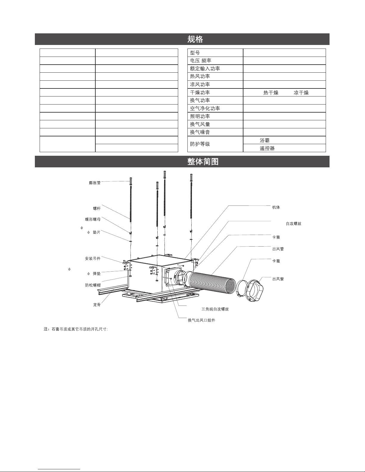
SPECIFICATIONS
Model
Voltage/Frequency
/
220V~/50Hz 220V~/50Hz
Rated Input Power
2150W 2150W
Heater Power
Fan Power
Dry Clothing Power
Ventilation Power
2125W 2125W
25W 25W
2125W(Hot)/25W(Cool) 2125W( )/25W( )
25W
25W
25W
25W
Air-care Power
Lighting Power
Ventilation Volume
Ventilation Noise
Ingress Protection
8W 8W
2.2m /min
3
2.2m /min
3
43dB 43dB
IPX2 (Bathroom Heater) IPX2 ( )
IPX4 (Remote Control) IPX4 ( )
SIMPLIFIED DIAGRAM OF THE UNIT
Note: Plaster or other ceiling opening dimension: 280 X 285 (mm)
280 X 285 (mm)
+5
0
+5
0
+5
0
+5
0
M6 Screw Rod
M6
6 Washer
6
6 Spring Washer
6
Hanger
M6 Screw Cap
M6
Keel
Body
Clamp
Clamp
Air Exhaust Pipe
BTP4*8 Triangular Self Tapping Screw
BTP4*8
Expansion Pipe
M6 Butterfly Nut
M6
BTP4*8 Self Tapping Screw
BTP4*8
Ventilation Outlet Assy.
Air Outlet Window
K-77316T-C-MZ
K-77316T-C-MZ
1325978-T01-A
Page 4

-3-
WIRING DIAGRAM
LED POWER
LED
HEATER
THERMOSTAT
THERMAL FUSE
OVER CURRENT FUSE
MOTOR
CAPACITOR
ALL-POLE SWITCH (OPTIONAL)
220V
50Hz
CN4
CN7
CN8
CN5
CN2
CN9
CN13
CN1
CN11
CN12
CN10
TEMPERATURE
AND HUMIDITY
SENSOR MODULE
AIR-CARE MODULE
STEPPER MOTOR
INDICATOR LIGHT
MODULE
THE RATE OF THE POWER SWITCH
MUST NOT BE LOWER THAN 250V 16A
250V 16A
YELLOW/GREEN
/
RED
BLUE
BLUE
BLUE
BLUE
RED
RED
RED
BLACK
BLACK
WHITE
WHITE
WHITE
WHITE
WHITE
WHITE
BROWN
GRAY
PINK
PINK
YELLOW
YELLOW
YELLOW
ORANGE
ORANGE
MAIN CONTROL CIRCUIT BOARD
+
+
+
+
+
+
There's no risk of damage to the insulation of power cord.
Copper cord must be inserted into the pillar terminal hole, and make
sure all the cords under the terminal are inserted into the pillar
terminal completely.
Suggest using a power cord which with specification 60227 IEC 53
Model's powercord Specified in GB/T 5023.5 and with cross section
of 3X1.0mm .
,
GB/T 5023.5 60227 IEC 53 ,
3X1.0mm
2
2
Terminal
Conductor
Insulation
8
(Unit: mm)
(: )
WARNING
Make sure the power cord installed firmly,
otherwise it may catch fire.
Conductor
Earth
Power Cord
8
8
13
10
1325978-T01-A
Page 5
-4-
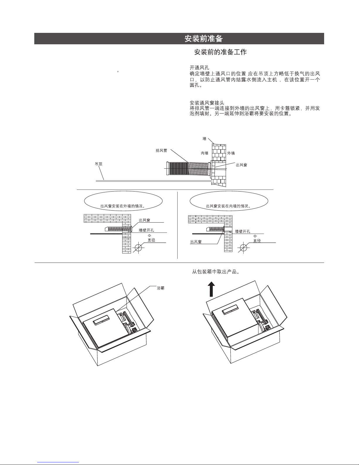
PREPARATIONS BEFORE INSTALLATION
A. Preparation before the installation A.
1. Open the hole of outlet window
Make sure that the outlet window s position (it should be
lower than the outlet of the bathroom heater to prevent the
water come back to the bathroom heater from the outlet
window), and open a round hole on the wall.
2. Outlet window installation
Fix the air exhaust pipe to the outlet window on the wall
with the clamp as the preparation of bathroom heater
installation. Seal the pipe and the outlet window with
foaming agent.
1.
(
)
2.
Ceiling
Air Exhaust Pipe
Wall
Inside
Outside
Outlet Window
The situation of outlet window on the
wall outside.
The situation of outlet window on the
wall inside.
Outlet Window
Outlet Window
Hole on the Wall
Hole on the Wall
80mm
80mm
115mm
115mm
B. Take out the bathroom from package. B.
Bathromm Heater
1325978-T01-A
Page 6

-5-
C. Packing List C.
1285547
80 Air Outlet Window
80
1285548
80 Air Exhaust Pipe
80
1285549
Clamp
2
1285550
Ventilation Outlet Assy.
1285552
Fixed Column Assy.
M6 Expansion Head
M6
10 Expansion Pipe
10
M6 Screw Rod
M6
1285553
Lock Assy. /
M6 Butterfly Nut
M6
6 Washer
6
6Spring Washer
6
M6 Nut
M6
Note: Initial Length:275mm
Stretch Length: 1300mm
275mm
1300mm
BTP4 8 Triangular
Self Tapping Screw
BTP4 8
270mm
1285556
Remote Control Base Assy.
Cover
*2
M4*25Screw
*2
Base
6 Plastic
Expansion Pipe
6*2
1285551
Heater Accessories Package
Hanger
Triangular
Self-tapping Screw
BTP4*8
1288669
Install Template
1285555
Remote Control
1325978-T01-A
Page 7

-6-
INSTALLATION
Caution before installation:
!
!
!
!
!
!
The installed product must be 200mm or above away from
curtains or other combustible materials.
The distance between the ceiling where the product is
mounted and the roof shall be 200mm or above.
Ensure that the gap between the product edge and the
wall is 300mm or above.
The power cord to the product shall have enough length
for the installation.
The distance between the product and the air outlet
window shall be 1000mm or lower.
Cut the screw rod(M6) to suit the distance between the
ceiling and the roof.
!
!
!
!
!
!
200mm
200mm
300mm
1000mm
(M6)
Air Exhaust Pipe
Wall
Lower than 1000mm
1000
300mm above
300
300mm above
300
Air Outlet Window
Bathroom Heater
1. Connecting the power cord
(1) Pass the power cord through the ceiling.
1.
(1)
Power cord
Decorated Plate
1325978-T01-A
Page 8

2. Fix the power cord to the bathroom heater
(1) Remove the screw on the wiring cover plate.
(2) Open the wiring cover plate.
(3) Lift the terminal protection cover.
(4) Loosen the screw fixing the power cord clip.
(5) Loosen the screw on the wiring terminal, insert the
power cord (not supplied) connected to the indoor fixed
line into the wiring terminal, tighten the wring terminal
screw.
(6) Fix the power cord with power cord clips. (The power
cord clip must pin the insulation sheath of power cord.)
(7) Use the screw removed in step (3) to fix the wiring
cover plate again.
2.
(1)
(2)
(3)
(4)
(5) (
)
(6) (
)
(7) (3)
3. Installing the Main Body Method 1 integrated ceiling.
integrated ceiling should be 300*300, 300*450, 300*600
(1) Disassembly the decorated plate around the position of
the product installation.
3.
300*300 300*450 300*600
(1)
()
300mm*300mm integrated ceiling
300mm*300mm
Disassembly 6 pieces
6
Disassembly 6 pieces
6
300mm*450mm integrated ceiling
300mm*450mm
300mm*600mm integrated ceiling
300mm*600mm
Disassembly 3 pieces
3
-7-
(2) Use the install template as the diagram to insert it into
the ceiling to mark the position of the drill.
(2) 90
300mm*300mm integrated ceiling
300mm*300mm
Bending line
Install Template
Install Template
Install Template
Cement Board
Power cord
LN
Wiring Terminal
274
198.5
1325978-T01-A
Page 9

-8-
(3) Fix the suspender on the right position of the cement
board, use the install template to adjust the M6 nut on
the suspender.
(4) Fix the suspension bracket on the suspender by 8
BTP4*8 screw.
(3)
M6
(4) 8 BTP4*8
M6 Butterfly Nut
M6
6 Washer
6
6 Spring Washer
6
M6 Nut
M6
M6 Nut
M6
BTP4*8 Triangular Self Tapping Screw
BTP4*8 (8 )
Suspender
Cement Board
Ceiling Surface
Install template datum line
(5) Fix the product on the M6 suspender by the suspension
bracket.
(5) M6
M6 Butterfly Nut
M6
6 Washer
6
6 Spring Washer
6
M6 Nut
M6
M6 Screw Rod
M6
1325978-T01-A
Page 10

-9-
(6) Install the air exhaust pipe
1) Fix the air exhaust pipe on the ventilation outlet assy.
by the clamp. The pipeline connected to outside of
the room must be slanted to prevent rain or
condensed water from flowing backwards.
(6)
1)
Outdoors
Indoors
Slant Taper
1
100150
~
()
BTP4*8 Triangular
Self Tapping Screw
BTP4*8 (1 )
80 Ventilation Outlet Assy.
80
Ventilation Outlet Assy.
Clamp
Air Exhaust Pipe
()
80mm
(7) Install the decorated plate and adjust the nut on the
suspender to keep them on the same horizontal surface.
Lock the nut after the adjustment.
(8) Install the remaining decorated plate (finish the product
installation)
(7) M6 M6
(8) ( )
Decorated Plate
Base
300mm*300mm integrated ceiling
300mm*300mm
1325978-T01-A
Page 11

4. Installing the Main Body Method 2 Ceiling mounting has
not been installed.
(1) Positioning and installation of the suspenders
1) Paste the install template attached along with the
product on the position where the main body is
intended to install.
4.
(1)
1)
Install Template
Cement Board
2) Fix the suspender to the cement board according to
the fixing position of the suspender as shown by the
install template.
2)
Cement Board
Suspender
-10-
(2) Fix the ventilation outlet assy. to the main body using
the BTP4*8 self-tapping screw.
(3) Fix the suspension bracket to the main body using the 8
BTP4*8 self-tapping screws.
(2) 1 BTP4*8
(3) 8 BTP4*8
BTP4*8 Self Tapping Screw
BTP4*8 (1 )
BTP4*8 Triangular
Self Tapping Screw
BTP4*8 (8 )
(4) Fix the product on the M6 suspender by the suspension
bracket. Lock the nut after the installation.
(4)
M6 Butterfly Nut
M6
6 Washer
6
6 Spring Washer
6
M6 Nut
M6
1325978-T01-A
Page 12

-11-
NOTE: When the ceiling is unable to dismantle, please
set a square inspection hole of at least 450mm.
450mm
(5) Install the air exhaust pipe
1) Fix the air exhaust pipe on the ventilation outlet assy.
by the clamp. The pipeline connected to outside of
the room must be slanted to prevent rain or
condensed water from flowing backwards.
(5)
1)
Outdoors
Indoors
Slant Taper
1
100150
~
()
Ventilation Outlet Assy.
Clamp
Air Exhaust Pipe
()
80mm
NOTE:
NOTE:
If the wall for installation is made of special material
(such as wood board, density board and etc.), suitable fixing
methods shall be adopted.
The place to install the remote controller shall not be
easily splashed by water.
Choose a mounting location for the remote holder.
Drilling two holes with depth larger than 45mm on the wall by
drill with a diameter of 6mm in accordance with the position of
screw holes on the remote control holder. Installing the
expansion tube into the holes.
Placing the installation holder on the fixing hole.
Fixing the holder with screws and install it.
Installing the screw covers on the screws.
Placing the remote controller on the holder.
6mm
45mm
INSTALLATION OF REMOTE CONTROLLER HOLDERINSTALLATION OF REMOTE CONTROLLER HOLDER
Remote Control
Cover
Screw
Base
Expansion Tube
INSTALLATION OF COIN BATTERYINSTALLATION OF COIN BATTERY
Please follow the installation diagram.
Coin Battery (CR2430)
1325978-T01-A
Page 13

-12-
USER'S GUIDE
A. Pairing
Connect to the power source, press the "HEATER and
together within 3 minutes to make the pairing.
"Beep, Beep, Beep" will be heard and the LED lamp will
be turned on if the pairing successfully.
"
"FAN"
!
A.
3
LED
!
B. Button Function B.
C. Display information C.
DOWN : Timer down
UP : Timer up
HEATER : Turn on the heater mode
FAN : Turn on the fan mode
DRY : Turn on the hot /cool dry clothes mode
VENTILATION : Turn on the ventilation/long time vent mode
24
AIR FLOW : Set the air flow swing or fixed
AIR-CARE : Turn on the air-care mode
LIGHT : Lighting on and off/chang the light color
/
STOP : Stop certain function
()
Hour
Minute
Celsius
Humidity
HEATER
FAN
HOT DRY
COOL DRY
24H VENTILATION 24
VENTILATION
AIR-CARE
AIR FLOW FIXED
SWING MODE
HEATER
FAN
1325978-T01-A
Page 14

-13-
D. Activated mode
During the standby mode, press any button to the
, display the room temperature and
humidity. Display will be turned off if no any further action
within 10 seconds.
During the working mode, display the room temperature
and humidity. Display will be turned off after the
countdown finish.
Press the function button, the "beep will be heard.
activated mode
"
!
!
!
D.
10
!
!
!
E. Time setting
Setting time could be changed during the "HEATER",
"FAN , "DRY", "VENTILATION" and "AIR-CARE" mode.
Setting time will be changed back to the default after each
use.
"HEATER": the default time is 6 hours, minimum time is
10 minutes, and maximum time is 6 hours.
"FAN": the default time is 6 hours, minimum time is 10
minutes, and maximum time is 6 hours.
"DRY : the default time is 6 hours, minimum time is 10
minutes, and maximum time is 6 hours.
"VENTILATION": the default time is 6 hours, minimum
time is 10 minutes, and maximum time is 6 hours.
"AIR-CARE": the default time is 2 hours, minimum time is
10 minutes, and maximum time is 2 hours.
"24H VENTILATION": the default time is 6 hours, the
setting time cannot be changed.
"
"
!
!
!
!
!
!
!
!
E.
+-
610
6
610
6
/610
6
610
6
210
2
24 24
!
!
!
!
!
!
!
!
TROUBLESHOOTING
Problem Diagnosis
Solution
Bathroom Heater does not
work.
The remote controller
does not display.
The remote controller
does not work.
Red LED is on.
Red LED is flash.
A. A power failure occurred.
A. The battery has been used up.
A. No pairing with the bathroom heater.
A. Temperature sensor error.
A. Dust filter need be clean.
B. The power cord is disconnected.
B. The polarity of battery was installed inversely.
B. The remote controller is used in an
inappropriate position or angle.
B. Humidity sensor error.
C. Circuit breaker is in the "Off" position.
C. No wake-up.
C. Low battery.
C. Heating system error.
A. Wait until the power is restored.
A. Please replace the battery.
A. Make the pairing.
Call the Customer Service Centre using the
information provided on the Compliance
Certification.
B. Connect the power cord into the junction box
of bathroom heater.
B. Please install the battery correctly.
B. Change the using position or angle to make
the controller towards the bathroom heater.
C. Turn on the power at the breaker.
C. Press any key to wake-up.
C. Change the battery.
A. Clean the filter or press the "+" for 2 seconds
in the Activated mode(Page 13).
1325978-T01-A
Page 15

A.
A.
A.
A.
A.
B.
B.
B.
B.
C.
C.
C.
C.
A.
A.
A.
B.
B.
B.
C.
C.
C.
A. P13
+2
CARE & CLEAN
1. Turn off power supply before maintenance or cleaning. If
Casing or Air Louver are covered with dust, do not splash
water onto it. Use only damp sponge or cloth to wipe dirt
off.
2. Do not use eradicator, abrasive powder or oil, acid or alkali
liquid detergent to clean casing or air louver.
3. Never try to put a small screw-driver or any other object
into the holes of air Louver from outside. This might cause
damage to the interior parts, and electric shock may occur.
4. Shut off the all-pole switch.
5. Wipe the front panel and the panel base with a soft cloth.
6. Remove the filter from the louver.
1.
2.
3.
4.
5.
6.
-14-
1325978-T01-A
Page 16

7. Use a vacuum cleaner to remove dust and dirt from the
filter.
8. Reinstall the filter assembly.
9. Turn on the all-pole switch.
10. Press the "+" for 2 seconds in the Activated mode(Page
13) to reset the filter cleaning indication.
7.
8.
9.
10. P13
+2
IMPORTANT CONSUMER INFORMATION
1. When AC power unit is connected to 220V AC power
supply, corresponding protective measures should be
taken.
2. Please confirm no water penetration at the connection area
of AC wire, and the connection area is not easy to be
affected by damp.
3. The head AC power supply must be protected with
appropriate fuse.
4. Please confirm the AC power supply should be shut off
before maintaining the products with AC power related.
5. All electrical connection must be compliance with related
regulation and codes.
6. All installation staff should be well familiar with installation
instruction.
Notice: Troubleshooting needs to be done by
professional of KOHLER CHINA. Users are not suggested
to do this without help. Please remember that the
checking and repairs done by users themselves could
easily cause damage to the machine or cause physical
harm to the person.
1. 220V
2.
3.
4.
5.
6.
-15-
1325978-T01-A
 Loading...