

Page 1
PowerWAVE 9000DPA
S2 (30-250 kVA)
User Manual
Page 2

TS_619_00 PW9000DPA S2 User Manual 13/3/17
Page 3

TS_619_00 PW9000DPA S2 User Manual 13/3/17
Document Control
PDF ISSUE DATE REVISION SUMMARY
TS_619_00B 19/01/17 Second draft copy
TS_619_00C 27/01/17 Third draft copy
TS_619_00D 09/03/17 Fourth draft copy
TS_619_00 13/03/17 First Issue
Page 4

TS_619_00 PW9000DPA S2 User Manual 13/3/17
Uninterruptible Power Supplies Ltd has taken every precaution to
produce an accurate, complete and easy to understand manual and will
therefore assume no responsibility nor liability for direct, indirect or
accidental personal or material damage due to any misinterpretation of or
accidental mistakes in this manual.
© 2017 Uninterruptible Power Supplies Ltd
This manual may not be copied or reproduced without written permission
of Uninterruptible Power Supplies Ltd.
USEFUL CONTACTS
www.upspower.co.uk UPS Limited web site
service@upspower.co.uk Service department – booking service, fault reporting etc.
technical@upspower.co.uk Technical queries
sales@upspower.co.uk Hardware sales
servicesales@upspower.co.uk Extended warranty agreements etc
Page 5

TS_619_00 PW9000DPA S2 User Manual 13/3/17 I
Table of Contents
Safety 1
1.1 Description of symbols used in this manual 1-1
1.2 User precautions 1-1
General Description 2
2.1 General introduction 2-2
2.1.1 Reliability and quality standards 2-2
2.1.2 Advanced design features 2-2
2.2 PW9000DPA S2 Model range 2-4
2.3 Functional description of operation 2-5
2.3.1 PW9000DPA S2 module block diagram 2-5
2.3.2 UPS Module operating modes 2-7
2.3.3 UPS System operating modes 2-9
2.3.4 Parallel system operation 2-10
2.4 PW9000DPA S2 User controls 2-11
2.4.1 DPA-50 Component identification 2-12
2.4.2 DPA-150 Component identification 2-13
2.4.3 DPA-250 Component identification 2-14
2.5 UPS Interface facilities 2-15
2.5.1 Customer Interface Board 2-15
2.5.2 Parallel Interface Board 2-16
2.6 Module control panel 2-16
2.6.1 Module control panel buttons 2-16
2.6.2 Module mimic LEDs 2-17
2.6.3 Power Management Display (PMD) 2-17
2.7 Warranty 2-21
2.8 Extended Warranty 2-21
2.9 Additional Service/Maintenance Support 2-21
Installation 22
3.1 Introduction 3-22
3.2 Taking receipt of the UPS 3-22
3.2.1 Reporting transportation damage 3-22
3.2.2 Weight and dimensions 3-23
3.2.3 Local transportation 3-23
3.2.4 Storage 3-24
3.2.5 Unpacking 3-24
3.3 Installation planning (environmental & mechanical) 3-25
3.3.1 Environmental considerations 3-25
3.3.2 Clearances 3-25
3.4 Installation planning (electrical) 3-27
3.4.1 General requirements 3-27
3.4.2 External maintenance bypass switches 3-29
3.4.3 Cable sizing 3-30
Page 6

:
II TS_619_00 PW9000DPA S2 User Manual 13/3/17
3.4.4 UPS Power connections 3-32
3.4.5 Battery configuration 3-33
External battery enclosure with separate battery configuration 35
External battery enclosure with common battery configuration 36
3.5 UPS Cabling procedure 3-37
3.5.1 Safety notes 3-37
3.5.2 Preparing the UPS power cabling 3-37
3.5.3 Connecting the UPS AC power cables 3-37
3.5.4 Connecting the battery cables 3-38
3.6 Customer Interface Board 3-38
3.6.1 Customer dry-port interface terminal block – X1 3-38
3.6.2 Customer interface output terminals – X2, X3, X4 3-39
3.7 Parallel-cabinet control and configuration 3-40
3.7.1 Parallel control bus 3-40
3.7.2 Multidrop 3-40
Operating Procedures 41
4.1 Introduction 4-41
4.1.1 Commissioning 4-41
4.1.2 Operating procedure summary 4-41
4.1.3 General warnings 4-42
4.2 Operating instructions 4-42
4.3 How to start the UPS system from a fully powered-down condition 4-42
4.4 How to start the UPS system from the maintenance bypass 4-44
4.5 How to transfer the load to maintenance bypass 4-45
4.6 How to shut down the complete UPS system 4-46
4.7 Operating in ‘on bypass’ mode 4-47
4.7.1 How to Turn ON the UPS in ‘on bypass’ mode 4-47
4.7.2 How to Turn OFF the UPS in ‘on bypass’ mode 4-47
4.7.3 How to transfer between ‘on bypass’ and ‘on inverter’ mode 4-47
Maintenance 48
5.1 Introduction 5-48
5.2 Scheduled maintenance 5-48
5.2.1 Preventative maintenance inspection 5-48
5.2.2 System calibration 5-48
5.2.3 Battery maintenance and testing 5-49
Troubleshooting 50
6.1 Alarms 6-50
6.2 Menu, Commands, Event Log, Measurements, 6-50
6.3 Fault identification messages and alarms 6-51
6.4 Contacting service 6-51
Options 52
7.1 Introduction 7-52
7.2 Customer interface board 7-53
7.2.1 Remote shut down customer input 7-53
7.2.2 Generator ON customer input 7-53
7.2.3 Battery temperature sensor 7-54
7.2.4 RS232 Computer serial interface – JD11 & USB 7-54
7.2.5 RS232 Interface for multidrop – JD12 7-54
7.2.6 SNMP/ CS141 slots – SLOT 1/ SLOT 2 7-55
Page 7

TS_619_00 PW9000DPA S2 User Manual 13/3/17 III
:
Specification 56
8.1 Mechanical Characteristics 8-56
8.2 Input Characteristics 8-57
8.3 Battery 8-57
8.4 Output 8-58
8.5 Standards 8-58
8.6 Environmental 8-59
Page 8

:
IV TS_619_00 PW9000DPA S2 User Manual 13/3/17
Page 9

TS_619_00 PW9000DPA S2 User Manual 13/3/17 1
1
Safety
1.1 Description of symbols used in this manual
1.2 User precautions
WARNING: The warning symbol is used where there is danger of an electrical shock, equipment damage or
personal-injury.
CAUTION: The caution symbol is used to highlight important information to avoid possible equipment
malfunction or damage.
WARNING: Keep this manual with the UPS for future reference.
WARNING: The UPS and peripheral equipment must be installed and commissioned by suitably qualified and
trained personnel who are aware of the potential shock hazards.
WARNING: Do not attempt to install this UPS system until you are satisfied that ALL the safety instructions and
hazard warnings contained in this manual are read and fully understood.
WARNING: High leakage current!
Ensure that the UPS has been correctly earthed before you connect the mains power supply!
WARNING: This UPS must not be started-up or put into use without having first been commissioned by a fully
trained engineer authorised by the manufacturer.
WARNING: All servicing must be performed by qualified personnel. Do not attempt to service the UPS
yourself.
You run risk of exposure to dangerous voltages by opening or removing the UPS-covers! Uninterruptible
Power Supplies Ltd will assume no responsibility nor liability due to incorrect operation or manipulation of the
UPS.
WARNING: The PW9000DPA S2 is a Class A UPS product (according to EN 62040-3). In a domestic
environment the UPS may cause radio interference. In such an environment the user may be required to
undertake additional measures.
Page 10

2 TS_619_00 PW9000DPA S2 User Manual 13/3/17
2
General Description
2.1 General introduction
Congratulations on your purchase of the PW9000DPA S2 UPS.
Continuous power availability is essential in today’s dynamic IT and process-related work environments. It is equally
important that any installed power protection system is sufficiently resilient and adaptable to handle any changes brought
about by the introduction of new server technologies, migration and centralization.
Such demands are well met by the PW9000DPA S2 UPS system which provides the foundation for continuous power
availability of network-critical infrastructures both in enterprise data centres, where business continuity has paramount
importance, and in process control environments where manufacturing continuity is essential.
The PW9000DPA S2 is a second generation high-power-density (HPD), leading-edge, double-conversion power
protection technology that has standardised on a modular component approach which helps speed deployment, improve
adaptability and increase system availability, while reducing total cost of ownership. It is a unique on-demand architecture
that integrates the power rack, power distribution unit, back-up battery and monitoring and management solutions to allow
easy selection of optimised configurations.
2.1.1 Reliability and quality standards
High reliability, upgrade ability, low operating cost and excellent electrical performance are just some of the highlights of
this innovative UPS solution.
By using a unique modular construction, and incorporating the latest technological developments in power engineering,
the PW9000DPA S2 represents a completely new generation of transformerless 3 phase UPS-System. Its advanced
double conversion VFI (Voltage and Frequency Independent) topology responds fully to both the highest availability and
environmentally friendly requirements compliant with IEC 62040-3 (VFI-SS-111) standards. The criteria and methods
which are used in the design, manufacture, and maintenance of Uninterruptible Power Supply systems are certified to
International Standard ISO 9001/EN 29001 and ISO 14001. A full UPS Specification is given in Chapter 8 of this manual.
Uninterruptible Power Supplies Ltd. specialises in the installation and maintenance of Uninterruptible Power Systems; and
this powerful UPS is just one example of our wide range of state-of-the-art power protection devices that will provide your
critical equipment with a steady and reliable power supply for many years.
2.1.2 Advanced design features
Key features
The highlights of this innovative UPS solution include:
• Decentralised Parallel Architecture (DPA) – Highest availability, with near zero down time.
• Truly modular design – The PW9000DPA S2 is designed around 30kVA, 40kVA,or 50kVA UPS modules.
• Hot-swappable modules – Enables system expansion and module replacement in a live system.
• Compact size, small foot print – Up to 342kW/m² saving on expensive floor space.
• Flexible battery management – Advanced management of battery charging and preventive-failure diagnostics.
• High ac-ac efficiency (up to 95.5%) even with partial loads – Results in energy and operational cost savings (TCO)
• Full power available from 0.9 lead to 0.8 lag – No de-rating required with leading power factor loads.
• Very low input current distortion – THDi = <3% @ 100% load leads to savings in generator-set power and
installation costs.
Page 11

TS_619_00 PW9000DPA S2 User Manual 13/3/17 3
2: General Description
Hot-swappable modules
In a redundant module system the unique ‘hot-swappable’ feature enables a UPS module to be added or removed from its
cabinet whilst the system is still powered. This can be done without disturbing the load or transferring it to the bypass
supply.
Note: In a non-redundant system the load will unavoidably have to be transferred to the bypass supply while a module is
shut down or removed from the system.
Advanced booster technology
The UPS module’s inbuilt advanced booster technology results in a perfect sinusoidal input power quality at 0.99 input
power factor with a harmonic content of less than 3-4% THDi. This leads to a more reliable system operation together with
savings in generator and transformer sizing due to reduced winding losses. It also means that the traditional input
harmonic filters, still used by some systems, are not required.
The high power factor presented by the UPS on the incoming mains supply minimises cabling and fusing costs due to the
reduced reactive power consumption which, together with the accompanying low harmonic currents, provides the
following benefits:
• No additional losses in wires and cables
• No extra heating of transformers and generators
• No over sizing of generators
• No false circuit breaker tripping and malfunction
• No erratic operation of computers, telecommunications, monitors, electronic test equipment etc.
• No resonance with power factor correction capacitors
Decentralised Parallel Architecture (DPA)
The PW9000DPA S2 system features DPA paralleling technology that provides n+x redundancy without introducing a
single-point-of-failure. Each module contains its individual charger and inverter power units, bypasses, CPUs, control
panels and separate battery configuration, and thereby offers completely autonomous operation.
This unique decentralized design:
• Enables a parallel redundant system providing 100% conditioned power at all time.
• Eliminates the system-level single point of failure inherent in traditional parallel UPS systems.
• Exponentially increases the reliability of the overall system.
Flexible battery management (FBM)
This equipment employs flexible battery charging management which avoids premature deterioration of battery life and
provides preventive failure diagnostics. The major benefits are:
• AC-ripple-free battery charging due to a dedicated dc-dc charger independent from the rectifier and inverter.
• Wide range of number of battery blocks (42-50 x 12V blocks, depending autonomy times).
• Wide UPS input voltage operating window extends the battery life due to fewer discharge cycles.
• Battery discharge protection caused by load jumps.
• Proactive battery protection from false manipulations and inadequate charging voltages.
• Proactive battery failure detection thanks to the Advanced Battery Diagnosis (ABD) algorithm.
• User-selectable battery tests to ascertain the battery state.
• Optional temperature compensated charging regime to enhance battery life.
Page 12
2: General Description
4 TS_619_00 PW9000DPA S2 User Manual 13/3/17
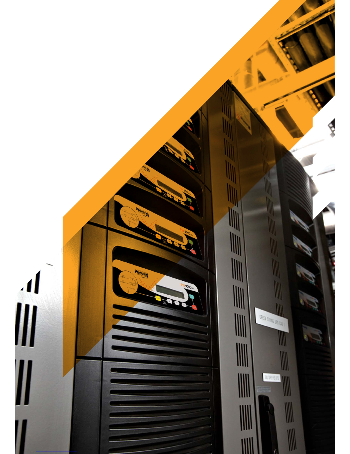
2.2 PW9000DPA S2 Model range
The PW9000DPA S2 UPS incorporates a rack-mountable design based on 30kVA, 40kVA and 50kVA plug-in UPS
modules fitted into one of three purpose-built cabinets. Each module is a self-contained UPS comprising a rectifier, battery
charger, inverter and static switch; and when two or more modules are fitted into a cabinet they effectively operate as a
parallel UPS system. The available cabinets are shown below in Figure 2.1.
The PW9000DPA S2 cabinets are identified as CLASSIC DPA-50, TRIPLE DPA-150 and UPGRADE DPA-250 – where
the model number represents the maximum kVA output when the cabinet is fully populated with 50 kVA UPS modules.
Figure 2.1 shows that the DPA-50 and DPA-150 cabinets also contain the UPS batteries; however the DPA-250 cabinet
requires an external battery cabinet, or battery rack. Uninterruptible Power Supplies Ltd. can supply a matching battery
cabinet which can installed adjacent to the DPA-250 cabinet in the majority of installations. An external battery cabinet can
also be added to the DPA-50 and DPA-150 models to extended the system’s autonomy time if desired.
Figure 2.1 PW9000DPA S2 Cabinets (frames)
Figure 2.2 PW9000DPA S2 UPS Modules
CAUTION: All the modules fitted within a cabinet must be of the same ra ting – for example, it is not possible to
mix 30kVA and 50kVA modules in the same cabinet.
CLASSIC DPA-50 TRIPLE DPA-150 UPGRADE DPA-250
UPS module capacity
Battery capacity
Max 1 module (30-50kVA)
280 x 7/9Ah batteries
3 modules (30-50kVA) 240x
7/9Ah batteries
5 modules (30-50kVA)
External batteries
Maximum power connection kVA 50 150 250
Dimensions (WxHxD) mm 730x1650x800 730x1975x800 730x1975x800
Weight of empty frame kg 262 239 205
Weight of frame with modules
fitted (but without batteries)
kg 305 - 309
(with 1 Module)
368 - 379
(with 3 Modules)
420 - 439
(with 5 Modules)
Colours Front: RAL 9007 + black (inlets). Sidewalls: Graphite grey
DPA 30 S2 Module DPA 40 S2 Module DPA 50 S2 Module
Output Apparent Power KVA 30 40 50*
Output Active Power KW 24 32 40
Output Power (PF=1) KVA / KW 24 / 24 32 / 32 40 /40
Number of 12V Battery Blocks No. 42-50 42-50 42-50
Dimensions (WxHxD) mm 663 x 225 x 720
Weight kg 43.1 45.3 46.8
Colours Front: Graphite grey
* On Inverter mode 50 KVA/40kW on Bypass mode 45 KVA/40kW
Page 13
TS_619_00 PW9000DPA S2 User Manual 13/3/17 5
2: General Description
2.3 Functional description of operation
This section describes:
• The internal operation of an individual UPS module at block-diagram level (see paragraph 2.3.1)
• The various operational modes of an individual UPS module (see paragraph 2.3.2)
• UPS system operational modes – ‘On-line’ versus ‘Off-line’ system operation (see paragraph 2.3.3)
• Multi-module system operation and paralleling considerations (see paragraph 2.3.4)
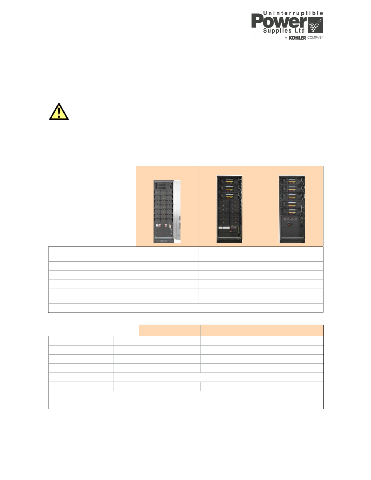
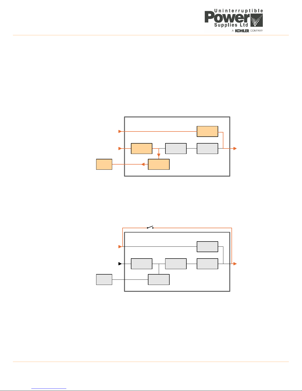
2.3.1 PW9000DPA S2 module block diagram
The PW9000DPA S2 UPS module is rack-mounted within the cabinet, and when the module is inserted into its rack it
plugs into a heavy-duty connector fitted to the back of the rack which carries all the module’s power connections – i.e.
input mains, bypass mains, battery and module power output.
Figure 2.3 PW9000DPA S2 module
Input power connections (1) / (2)
The UPS input mains and bypass mains are connected to an input power terminal block located in the lower part of the
UPS cabinet. Both inputs require a 3ph+N feed but, although the two inputs are shown as being separate in Figure 2.3, in
a standard installation the input mains terminals (1) and bypass mains terminals (2) are usually linked at the cabinet’s
input power terminal blocks so only one mains supply feed is required.
The input supplies are unswitched within the UPS cabinet and connected directly to each fitted module.
Both input supplies are fused within the module (F1/F2), however the fuses are internal to the module and not accessible
to the operator. In the event of a fuse failure the module must be removed and repaired by an authorised service agent. A
fuse failure event is shown on the module control panel to identify a faulty fuse.
Within the UPS module, the input supplies are connected to the module’s power blocks through individual supply
contactors which are driven by the module’s control logic and operate as part of the module’s start/stop sequences. They
are also used by the control system to isolate the input power within the module following certain fault conditions.
CAUTION: As the mains power supplies are unswitched within the UPS cabinet, the module(s) will be live at all
times unless the input/bypass supply is isolated at the external mains switchboard panel.
RECTIFIER
BATTERY
EXTERNAL
BATTERY
CABINET
INVERTER
STATIC
SWITCH
BOOSTER /
CHARGER
Bypass
Contactor
Inv. Output
Contactor
Input
Contactor
Bypass Mains
IA-2
IA-1
F4
F1
F2
F3
UPS MODULE
UPS CABINET
Static bypass line
Maintenance bypass line
UPS Input Mains
UPS Output
to critical load
3
4
1
2
5
6
7
8910
Page 14

2: General Description
6 TS_619_00 PW9000DPA S2 User Manual 13/3/17
Battery connections (3)
Each UPS module is connected to a battery string via a dedicated fused isolator. Ideally, each module is connected to an
individual battery but in some installations a common battery is shared between two (or more) modules.
The battery fuse (F3) is fitted inside the module and is not accessible to the operator. If the fuse ruptures, the module must
be removed and repaired by an authorised service agent. A fuse failure message is shown on the module control panel.
• DPA-50 (1 module) – The batteries are housed internally in the UPS cabinet and connected to the module through
a fused isolator (F4) located on the cabinet’s power panel.
• DPA-150 (3 modules) – The batteries are housed internally in the UPS cabinet and connected to the module
through three fused isolators annotated F4/ F5/ F6 (for modules 1, 2, and 3 respectively).
• DPA-250 (5 modules) – The batteries are housed in a separate battery cabinet (or rack) which must also contain
the fused isolators. There are no battery isolators within the UPS cabinet itself.
Output power connection (4)
A ‘parallel isolator’ switch (IA-2) is connected between the UPS module output and the cabinet’s output (load) terminal
block. IA-2 is used to disconnect the module from the UPS output; for example, when replacing a module in a redundant
parallel system, or when operating on maintenance bypass.
In the DPA-150 and DPA-250 cabinets, a dedicated ‘parallel isolator’ switch (IA-2) is provided for each UPS module. The
isolators are located on the cabinet’s power panel and identified as IA2-1, IA2-2, IA2-3.... (for modules 1, 2, and 3
respectively)
Maintenance bypass (5)
The maintenance bypass switch (IA-1) is external to the UPS module(s) and located on the cabinet’s power panel. This
switch connects the UPS cabinet output (load) terminals directly to the bypass mains terminals and is used to connect the
load to the (unprotected) bypass supply if the UPS modules have to be shut down due for service repair etc. See also
paragraph 3.4.2.
Rectifier (6)
The rectifier converts the UPS input mains supply into a regulated DC power source which provides the operating power
for the inverter. It uses leading-edge switched-mode techniques which results in a UPS module input power factor of
almost unity over its operating range (0.99 at full rated linear load). The rectifier can provide 100% inverter power demand
over an input voltage range of -20% to +15%. This wide input voltage operating range means that the battery is not called
upon during substantial power dips (brown outs), which in turn maximises the battery life and availability.
Battery booster/charger (7)
This block has bi-directional functions. When the input mains supply is available, and the rectifier is turned on, the booster/
charger acts as a multi-stage battery charger. The charger uses an intelligent charging profile to optimise the battery life
and at the same time ensure the battery recharges quickly following a deep discharge cycle.
If the input mains supply fails, or the rectifier is unable to provide a sufficient output to satisfy the prevailing inverter load,
the battery provides the inverter’s DC operating power source. The booster/charger circuit boosts the battery voltage as
the battery discharges and regulates it at a suitable level to allow the inverter to operate correctly.
Inverter (8)
The inverter converts the DC voltage produced by the rectifier (or the battery via the DC boost converter) into a sinusoidal
AC output voltage suitable to connect to the load. In addition to providing output voltage regulation, the inverter control
logic also provides various levels of overload protection, freq
uency regulation and synchronisation, and output voltage
error detection.
Static switch (9)
The static switch provides a means of connecting the UPS module output to the static bypass line – which is in turn
connected to the UPS bypass mains supply. Working in conjunction with the output contactor, the static switch control
logic is used to transfer the UPS output between the inverter and bypass mains without a break in the load supply.
Note: A brief load break will occur if transferring from bypass to inverter following a bypass supply failure. (See ‘Off Line
Mode’ in paragraph 2.3.3).
Page 15
TS_619_00 PW9000DPA S2 User Manual 13/3/17 7
2: General Description
Inverter output contactor (10)
The inverter output contactor is driven by the UPS module’s control logic and operates in conjunction with the static switch
as part of the bypass/inverter load transfer process. The contactor is also used to isolate the inverter from the UPS output
within the module following certain overload or fault conditions.
2.3.2 UPS Module operating modes
Simplified block diagrams are used in this section to illustrate the various UPS module operating modes. Note that where
two or more UPS modules are installed in a DPA-150 or DPA-250 cabinet they will always adopt the same operating mode
due to their parallel control signals.
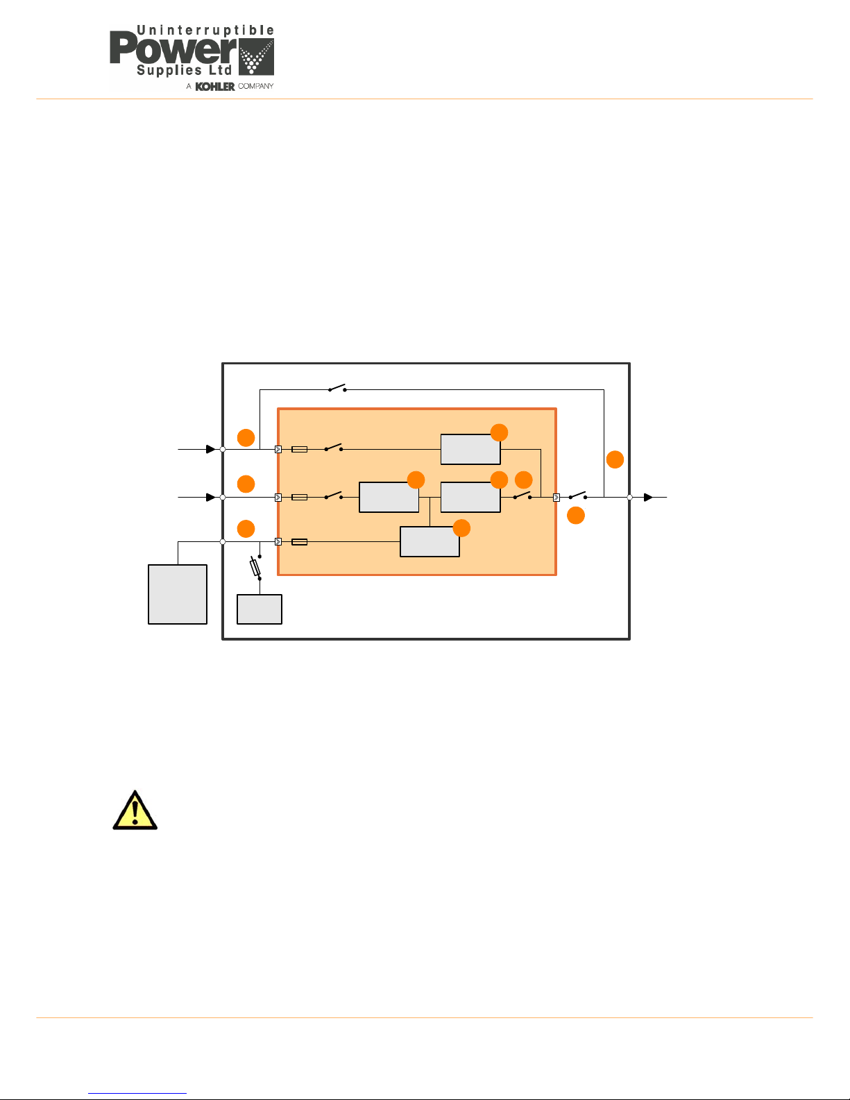
Load on inverter
This is the only operating
mode that provides the
load with continuously
processed and backedup power: and in the
majority of installations
can be considered as
the ‘normal’ operating
mode.
In this mode, the input
mains AC supply is
converted to DC by the
rectifier which then
charges the battery and
provides the operating power for the inverter.
The inverter converts the DC produced by the rectifier back to an AC power source which is then connected to the load via
the inverter output contactor. The inverter frequency is synchronised to the bypass supply provided the bypass frequency
remains within preset limits. If these limits are exceeded, or if the bypass supply fails altogether, the inverter frequency
control reverts to a free-running oscillator which produces a constant 50Hz or 60Hz UPS output.
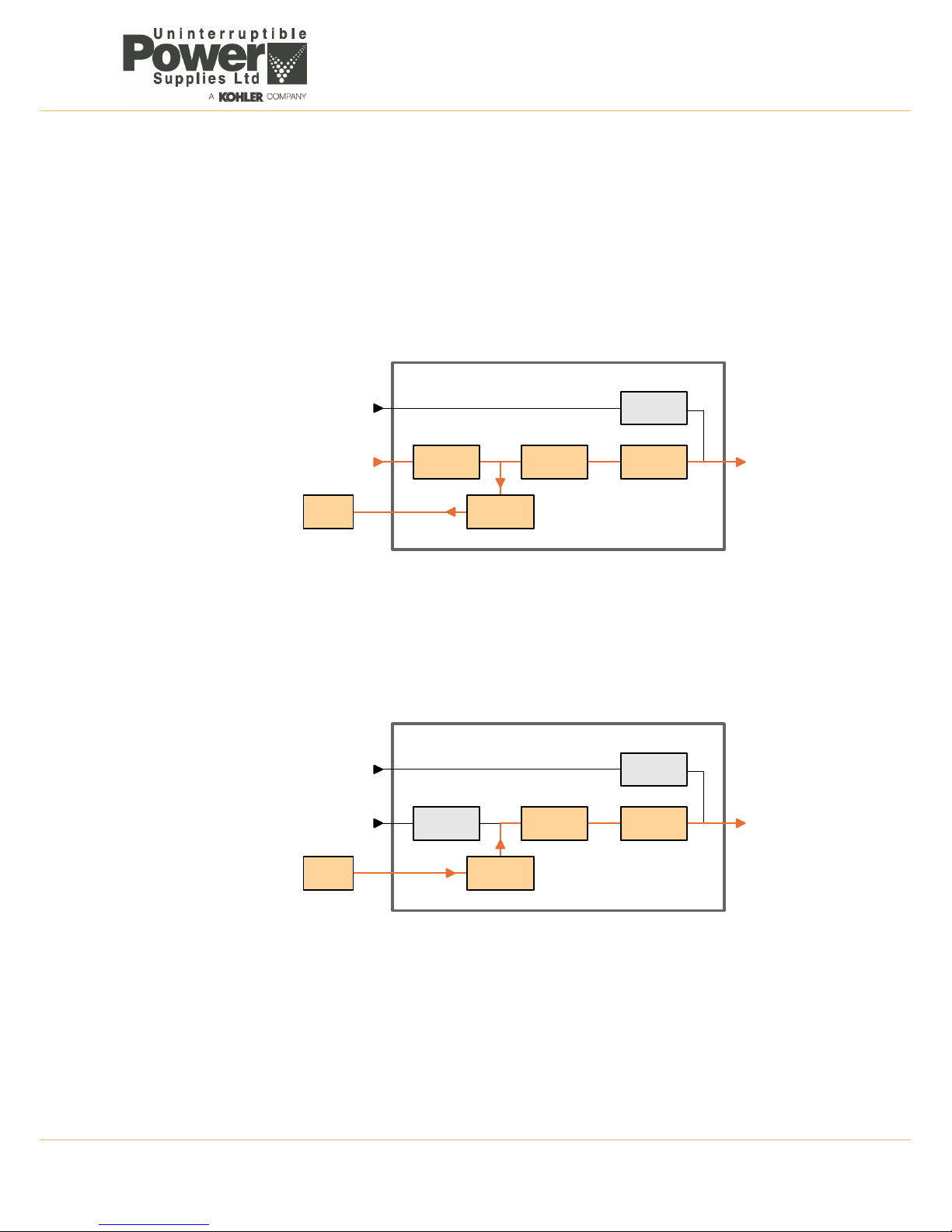
Load on battery
If the mains supply fails,
the rectifier shuts down
and the battery provides
the DC power source for
the inverter. The battery
voltage is regulated by
the booster circuit to
ensure the inverter
receives a suitable DC
input as the battery
discharges. On the
module control panel the
BATTERY LED will flash
green to indicate that it is
on load.
In the case of a dual feed input – if the bypass supply is still live when the input mains supply fails, the inverter frequency
remains synchronised to the bypass mains provided it is within its preset limits.
In the case of a single feed input – the bypass supply will fail at the same time as the input mains supply and the inverter
frequency control reverts to its free-running oscillator and will provide a constant 50Hz or 60Hz UPS output.
Battery discharge operation
When the battery is placed on load, and begins to discharge, the BATTERY mimic LED flashes green on the module
control panel accompanied by an audible alarm. The LED continues flashing green until the remaining autonomy time falls
RECTIFIER
BATTERY
INVERTER
STATIC
SWITCH
BOOSTER /
CHARGER
INV. Output
Contactor
Bypass Mains
UPS MODULE
Static bypass line
UPS Input Mains
UPS Output
to critical load
Figure 2.4 Load on inverter
RECTIFIER
BATTERY
INVERTER
STATIC
SWITCH
BOOSTER /
CHARGER
INV. Output
Contactor
Bypass Mains
UPS MODULE
Static bypass line
UPS Input Mains
UPS Output
to critical load
Figure 2.5 Load on battery
Page 16
2: General Description
8 TS_619_00 PW9000DPA S2 User Manual 13/3/17
to three minutes, whereupon it begins flashing red. This allows the operator to gauge the remaining autonomy time and,
where necessary, shut down the load in an orderly manner (e.g. save data) before the battery is fully discharged. Various
options are available to automate the load shut down process and if an automated data protection application is installed it
usually begins its automatic shut down routine at this point.
The initial audible alarm can be cancelled but it will reappear when the battery voltage falls to its LOW BATTERY alarm
threshold, whereupon the audible alarm sounds once again to warn the operator that the battery is nearing its end-ofdischarge.
Eventually, the BATTERY LED changes to solid red when the battery reaches its fully discharged voltage, and the UPS will
attempt to transfer the load to the bypass supply if the supply is present.
Load on bypass
In the ‘load on bypass’
mode the static switch
connects the load to the
unprotected static
bypass line.
This mode can be
selected manually (see
‘ECO Mode’ below) or
entered as the result of a
UPS fault (or overload)
condition which transfers
the load to bypass
because the inverter is
unable to support it.
Depending on the reason for entering the ‘load on bypass’ mode, the rectifier and charger sections might be turned off
entirely or remain operational and continue to provide battery charging (as shown above). Similarly, the inverter may have
been manually turned OFF or shutdown due to a fault, and the INVERTER LED on the module control panel may be either
OFF or solid RED.
Module OFF (Maintenance bypass)
When the UPS module
is turned OFF, all of its
internal power blocks
are effectively shut down
but the module input
power terminals remain
live unless the UPS
input/bypass mains are
externally isolated.
The maintenance
bypass switch (IA-1) can
be closed to maintain the
load supply, but in a
single UPS cabinet
installation this requires
the bypass mains supply
to remain live and
thereby prevents the bypass supply from being externally isolated.
Only one maintenance bypass switch is fitted per UPS cabinet and if the cabinet contains several modules (DPA-150,
DPA-250) the maintenance bypass switch (IA-1) bypass them all.
When operating a multi-cabinet system, the internal cabinet maintenance bypass switch (IA-1) should not be used, and an
external maintenance bypass installation that wraps-around the complete multi-cabinet system is required – usually
installed in a dedicated maintenance bypass cabinet, or wall-mounted as described in paragraph 3.4.2.
RECTIFIER
BATTERY
INVERTER
STATIC
SWITCH
BOOSTER /
CHARGER
INV. Output
Contactor
Bypass Mains
UPS MODULE
Static bypass line
UPS Input Mains
UPS Output
to critical load
Figure 2.6 Load on bypass
RECTIFIER
BATTERY
INVERTER
BOOSTER /
CHARGER
INV. Output
Contactor
Bypass Mains
UPS MODULE
Static bypass line
UPS Input Mains
UPS Output
to critical load
IA-1
Maintenance bypass line
STATIC
SWITCH
Figure 2.7 Module OFF (Load on maintenance bypass)
Page 17

TS_619_00 PW9000DPA S2 User Manual 13/3/17 9
2: General Description
2.3.3 UPS System operating modes
Section 2.3.2 described the operating modes for the individual UPS modules: but UPS systems are also categorised
according to the way in which they operate at a ‘system’ level, and are typically described as being either an ‘on-line’, or
‘off-line’ (‘line interactive’) system.
The PW9000DPA S2 can be operated in either of these categories.
ON-LINE UPS system
An ‘on-line’ system provides the highest degree of load protection, especially if the utility mains supply suffers a
disturbance or complete failure, and we always recommended this mode of operation if the critical load will not tolerate
even a very brief supply interruption – e.g. in the case of a computer system.
When the PW9000DPA S2 is used as an ‘on-line’ system, the UPS modules normally operate in their ‘on inverter’ mode
(Figure 2.4), and switch to the ‘on battery’ mode if the input mains supply fails (Figure 2.5). The changeover to battery
operation is totally transparent at the UPS output and an audible and visual alarm warns the operator that the battery is
discharging to enable any intervention to be taken to protect the load integrity.
The UPS then continues to provide its rated output until the battery discharges to a low cut-off point at which time the UPS
attempts to switch to its ‘on bypass’ mode. If the bypass is unavailable the UPS shuts down in a controlled manner.
It is usual, especially in larger installations, to provide the UPS with an alternative input supply from a standby generator
which starts automatically following a UPS input mains failure; and where this is implemented the batteries only discharge
for a short period, until the generator comes on-line. This not only avoids the UPS shutting down due to a fully discharged
battery but also helps maximise the battery life cycle.
If the UPS experiences an internal fault during ‘on-line’ operation, the inverter turns off and the static switch transfers the
load to bypass mains automatically and without interruption – provided the inverter is synchronised to the bypass. If there
is an output overload, the inverter can supply the overload for a limited time, depending on its severity, and if the permitted
time is exceeded the load transfers to bypass. The additional power available from the bypass supply will attempt to clear
the overload but if it persists it will ultimately rupture the bypass mains supply fuses. If the overload condition clears while
operating on bypass it re-transfers the load to the inverter and the UPS returns to its normal ‘on-line’ mode of operation.
OFF-LINE (On stand-by) UPS system operation
When the PW9000DPA S2 is used as an ‘off-line’ system, the UPS modules are normally operated in their ‘on bypass’
mode (Figure 2.6) with the load supplied via the static bypass line. However the rectifier and battery charger are still
powered up and maintain battery charging, and the inverter section is turned on and operating on standby.
Operating in this mode is slightly more energy efficient than operating in the ‘on-line’ mode due to the reduced rectifier and
inverter losses during normal system operation; and it is sometimes referred to as the “ECO” (economy) mode. However,
this mode is recommended only if the connected load equipment can tolerate power interruptions of up to 3~5 ms during
the transfer period.
If the bypass supply fails, the inverter is immediately brought on line and the load is transferred from the bypass line to the
inverter within 3 to 5 milliseconds. If the UPS bypass mains and input mains are connected to separate sources (dual
feed) and the input mains is still live when the load is transferred, the UPS modules will operate in their ‘on inverter’ mode
(Figure 2.4). However, if the input/bypass mains supplies are c
onnected to a common feed, or the input mains is
unavailable in a dual feed system, the modules immediately revert to the ‘on battery’ mode (Figure 2.5).
When the bypass supply returns to normal, the load re-transfers to the static bypass line (without a break) and the inverter
returns to its standby operation.
Note: if the bypass is unavailable it is unable to take over the load supply if the inverter fails, or assist the inverter han dle
an output overload. It is therefore important that the cause of the load transfer from bypass to inverter is quickly rectified.
WARNING: The ON-LINE mode should always be used for critical load protection.
Page 18

2: General Description
10 TS_619_00 PW9000DPA S2 User Manual 13/3/17
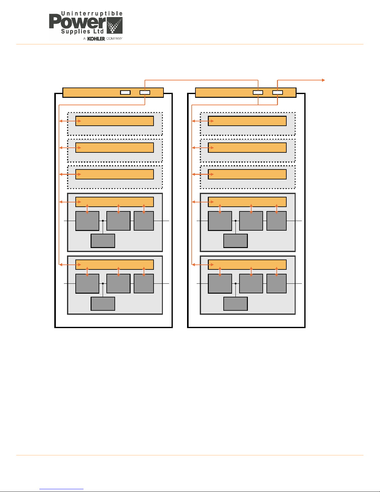
2.3.4 Parallel system operation
All the modules fitted in a UPS cabinet inherently operate as a parallel system as their outputs are connected in parallel at
the cabinet’s output terminals. The electronic control system built into each module ensures that:
• The modules are always frequency-synchronised to each other – and to the bypass mains (when present).
• The modules equally share the load current.
• The modules’ load transfer operation is synchronised such they ALL transfer their output between inverter and
bypass simultaneously when commanded from any one module.
The PW9000DPA S2 UPS system can be expanded by connecting up to six PW9000DPA S2 UPS cabinets in parallel;
and when two or more cabinets are connected in this way, all the UPS modules within them are effectively paralleled
together. For example: a maximum system capacity is obtained by connecting together six DPA-250 cabinets, each fully
populated with DPA-50 modules, which results in a total of thirty (50kVA) modules operating in parallel to provide a system
capacity of 1500kVA.
System expansion
Some UPS applications present a low initial power requirement which increases over time as the application grows; and it
is therefore essential that the installed UPS system can be expanded to meet the growing demand without compromising
the existing load. This requirement is well met with the ‘hot swappable’ feature of the PW9000DPA S2 UPS modules,
whereby an additional module can be inserted into a vacant slot in an existing cabinet without disturbing the load.
Note: If the expansion requires an additional cabinet the system will have to be shut down while the cabinet is installed.
‘Capacity’ versus ‘redundant module’ system
A parallel UPS system can be operated as either a ‘capacity’ or ‘redundant’ module system.
A ‘capacity’ system is rated such that ALL the UPS modules are required to furnish the specified full load power and the
loss of one module will automatically transfer the load to the bypass supply.
In a ‘redundant-module’ system, the system contains at least one UPS module over and above that required to supply the
full load and it is possible to lose a module without transferring the load to the bypass supply or in any way disrupt the UPS
output. A system operating with a redundant module is inherently the most reliable.
A parallel system operating with one redundant module is known as an ‘N+1’ system.
Parallel control bus
All the UPS modules within a cabinet, and between cabinets, are connected to a parallel control bus which carries several
control signals used for frequency synchronisation, load sharing etc. Each UPS module can electronically compare its own
frequency and output current with that of its neighbouring module and make any necessary fine adjustments to its control
logic to achieve balanced conditions across the system.
The parallel control logic observes one UPS module as being the ‘master’ and the others as ‘slaves’. However if the
‘master’ module goes faulty at any time the next module in the chain (a former ‘slave’) will immediately take over the role
of ‘master’ and the former ‘master’ module will turn off. The ‘master/slave’ configuration is set during commissioning.
During commissioning, the UPS modules are also assigned a numerical ID according to their position in the cabinet, with
the bottom module being given the lowest number. Figure 2.8 shows two DPA-250 cabinets with the modules in cabinet 1
assigned an ID of ‘P01’ to ‘P05’ and those in cabinet 2 an ID of ‘P06’ to ‘P10’ (‘P’ indicates that the modules are part of a
Parallel system). The module ID is used by the control and monitoring logic.
Key Point: When planning a multi-cabinet system, it is not necessary to fully populate one cabinet with UPS
modules before installing the next cabinet. For example, if it is known at the outset that a 200kVA initial load
requirement is likely to increase to 400kVA, it makes sense to install and cable-up two DPA-250 cabinets and
distribute the initial requirement of four UPS modules between them.
Page 19
TS_619_00 PW9000DPA S2 User Manual 13/3/17 11
2: General Description
Figure 2.8 PW9000DPA S2 – Parallel cabinet system
2.4 PW9000DPA S2 User controls
The following illustrations show the location of the PW9000DPA S2 power switches and fused isolators that are used
when operating the equipment. The module control panel (one per UPS module) is described in paragraph 2.6.
STATIC
SWITCH
INVERTERRECTIFIER
Parallel Control Logic
UPS Module P06
CHARGER
STATIC
SWITCH
INVERTERRECTIFIER
Parallel Control Logic
UPS Module P07
CHARGER
Parallel Control Logic
UPS Module P08
Parallel Control Logic
UPS Module P09
Parallel Control Logic
UPS Module P10
UPS CABINET 2
STATIC
SWITCH
INVERTERRECTIFIER
Parallel Control Logic
UPS Module P01
CHARGER
STATIC
SWITCH
INVERTERRECTIFIER
Parallel Control Logic
UPS Module P02
CHARGER
Parallel Control Logic
UPS Module P03
Parallel Control Logic
UPS Module P04
Parallel Control Logic
UPS Module P05
UPS CABINET 1
Parallel Adapter Board
To JD5 in UPS CABINET 3
JD5 JD6
ParallelAdapter Board
JD5 JD6
Page 20
2: General Description
12 TS_619_00 PW9000DPA S2 User Manual 13/3/17
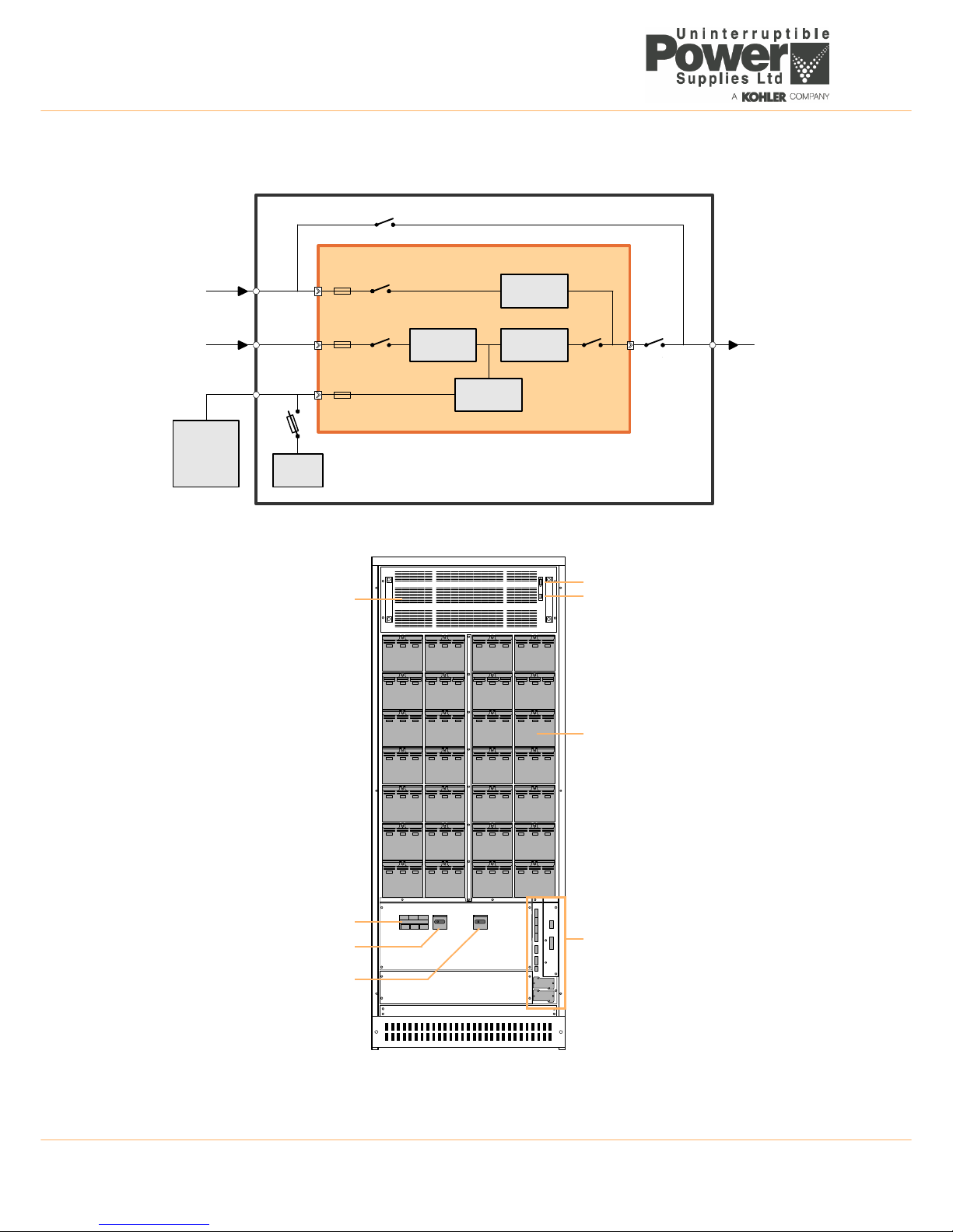
2.4.1 DPA-50 Component identification
Figure 2.9 DPA-50 Cabinet details
Battery trays
UPS Customer Interface connections
(described in the Options chapter).
[F4] Battery fuse
[IA2] Parallel Isolator
[IA1] Maintenance Bypass Isolator
UPS Module
JD1 Smart Port – RS232 (Sub-D9P)
JD7 Module control panel connector
RECTIFIER
BATTERY
EXTERNAL
BATTERY
CABINET
INVERTER
STATIC
SWITCH
BOOSTER /
CHARGER
Bypass
Contactor
Inv. Output
Contactor
Input
Contactor
Bypass Mains
IA-2
IA-1
F4
F1
F2
F3
UPS MODULE
UPS CABINET
Static bypass line
Maintenance bypass line
UPS Input Mains
UPS Output
to critical load
Page 21
TS_619_00 PW9000DPA S2 User Manual 13/3/17 13
2: General Description
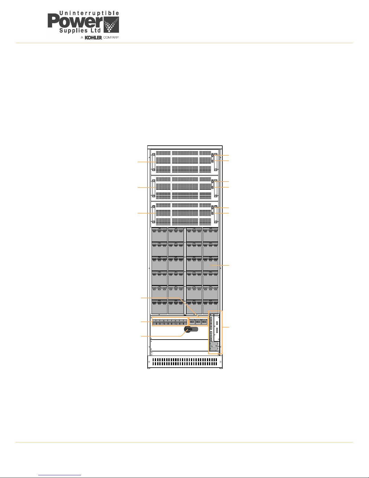
2.4.2 DPA-150 Component identification
Up to three UPS modules can be fitted, with the lower-most module identified as module 1.
The battery fuses are identified F4 to F6. F4 is associated with module 1, F5 with module 2 and F6 with module 3.
The parallel isolator switches (IA2) are labelled to identify their associated UPS module – e.g. IA2-2 pertains to module 2.
Figure 2.10 DPA-150 Cabinet details
Battery trays
UPS Customer Interface connections
(described in the Options chapter).
Parallel Isolator (1 per module)
[IA1] Maintenance Bypass Isolator
UPS Module P03
UPS Module P02
UPS Module P01
[IA2-1] [IA2-2] [IA2-3]
Battery fuse (1 per module)
[F4] [F5] [F6]
JD1 Smart Port – RS232 (Sub-D9P)
JD7 Module control panel connector
JD1 Smart Port – RS232 (Sub-D9P)
JD7 Control Panel connector
JD1 Smart Port – RS232 (Sub-D9P)
JD7 Control Panel connector
Page 22

2: General Description
14 TS_619_00 PW9000DPA S2 User Manual 13/3/17
2.4.3 DPA-250 Component identification
The DPA-250 contains no batteries and can be fitted with up to five UPS modules, with the lower-most module identified
as module 1.
The module parallel isolator switches (IA2) are labelled to identify their associated UPS module – e.g. IA2-2 pertains to
power module 2.
Figure 2.11 DPA-250 Cabinet details
UPS Customer Interface connections
(described in the Options chapter).
Parallel Isolator (1 per module)
[IA1] Maintenance Bypass Isolator
UPS Module P05
UPS Module P04
UPS Module P03
[IA2-1] [IA2-2] [IA2-3] [IA2-4] [IA2-5]
UPS Module P02
UPS Module P01
JD1 Smart Port – RS232 (Sub-D9P)
JD7 Module control panel connector
JD1 Smart Port – RS232 (Sub-D9P)
JD7 Control Panel connector
JD1 Smart Port – RS232 (Sub-D9P)
JD7 Control Panel connector
JD1 Smart Port – RS232 (Sub-D9P)
JD7 Control Panel connector
JD1 Smart Port – RS232 (Sub-D9P)
JD7 Control Panel connector
Page 23

TS_619_00 PW9000DPA S2 User Manual 13/3/17 15
2: General Description
2.5 UPS Interface facilities
Figure 2.12 UPS Interface Boards
Two interface boards are fitted in the lower right-hand side of the UPS cabinet, adjacent to the UPS power switches. One
is the Customer Interface Board and the other is the Parallel Interface Board.
2.5.1 Customer Interface Board
The customer interface board provides a number of input/output connections that can be used by the customer to
interface the UPS cabinet with a range of external monitoring and control systems – e.g. as part as a building
management system (BMS). The available interfaces are shown in Figure 2.12:
The dry-port I/O connection details are shown in the Installation chapter of this manual (see Paragraph 3.6).
Multidrop
The optional ‘Multidrop’ feature, which is available only in a parallel system, allows the customer interface board in the
‘master’ cabinet to collect data/messages from the other system cabinets. The received data is then processed at a
centralised point on the ‘master’ customer interface board and made available to the user directly on the RS232 port
(JD1). It is also transmitted to the CS141 card if inserted in the relevant slot.
Key Point: The Parallel Interface Board is part of the factory-fitted ‘paralleling kit’ and is installed only in UPS
cabinets used in a parallel system.
Key Point: When the UPS cabinet is installed as part of a parallel system the customer interface board I/O is
disabled in the ‘slave’ cabinets if the system ‘Multidrop’ application is enabled.
2
3
4
6
8
9
5
7
1
Customer Interface Board
1 X1 Customer inputs (terminal block)
2 X2-X4 Customer dry port output (terminal blocks)
3 JD11 RS232 PC interface (Sub D-9 Female)
4 JD12 RS232 Multidrop (Sub D-9 Male)
5 USB PC Interface
6 SLOT 1 Slot for SNMP (CS141 adapter)
7 SLOT 2 Slot for optional Modem/Ethernet card
Parallel Interface Board (fitted in a parallel UPS cabinet only)
8 SW1-9 Parallel cabinet configuration DIP switch
9 JD8 Parallel bus connector via Parallel Adapter Board
Page 24

2: General Description
16 TS_619_00 PW9000DPA S2 User Manual 13/3/17
This facility requires a purpose designed ‘Multidrop’ cable to be connected between each module’s customer interface
board JD12.
Note that when the multidrop feature is used, the I/O facilities of customer interface board in the ‘slave’ cabinets are all
disabled, but the customer interface board fitted to the ‘master’ cabinet remains fully functional.
2.5.2 Parallel Interface Board
The parallel interface board facilitates the connection of the parallel control bus cables between the cabinets in a parallel
cabinet system. These cables are connected to a ‘Parallel Adapter’ board which is fitted to JD8.
2.6 Module control panel
A door-mounted module control panel is provided for each UPS module. The control panel is used to start and stop the
module, command a load transfer between inverter and bypass, and monitor the module’s operating parameters. It is also
used to configure and interrogate the module during commissioning and troubleshooting.
Figure 2.13 Module control panel
2.6.1 Module control panel buttons
The module control panel buttons allow you to:
• Start-up and shut down the UPS and transfer the load between inverter and bypass.
• Monitor and display the UPS operating voltages, currents, frequencies and other values on the LCD display.
• Reset/cancel an alarm.
Button function summary
ON/OFF Buttons
You can switch the UPS ON or OFF by simultaneously pressing both ON/OFF buttons (for less than 1s). The requirement
to press both buttons is to help prevent accidental operation.
BUTTON FUNCTION
ON/OFF Used to switch-on or switch-off the UPS by pressing both buttons simultaneously
UP
)
Scroll upwards through a displayed menu
DOWN
()
Scroll downwards through a displayed menu
ENTER Selects a chosen menu item
RESET Cancels an audible alarm. If the alarm condition is transient the ALARM LED will turn OFF, otherwise it will remain ON
Power Management Display (PMD)Mimic LED Indicators
Menu navigation &
Alarm & Reset
selection buttons
Module ON/OFF
control buttons
Page 25

TS_619_00 PW9000DPA S2 User Manual 13/3/17 17
2: General Description
Pressing the two ON/OFF buttons during normal operation will immediately shut down the UPS module.
• In a single module system (e.g. DPA-50) this disconnects the UPS from the load unless the load is first transferred
to the maintenance bypass.
• In a parallel module system the UPS module shuts down and is disconnected from the load: however the load may
or may-not transfer to the static bypass, depending on whether or not the number of remaining on-line UPS
modules satisfies the system’s redundancy – i.e. if there is a sufficient number of modules remaining to support the
system’s load then the load is not transferred.
Note: To shut down all the UPS modules in a parallel system you must press both ON/OFF buttons on every module.
2.6.2 Module mimic LEDs
The mimic diagram LEDs indicate the general power flow through the UPS module and changes colour between Green
and Red (and OFF) to indicate the prevailing UPS module operating conditions.
LED Indication summary
* The ALARM LED is a visual indication of an internal or external alarm condition. When activated, it is accompanied by an
audible warning which can be cancelled by pressing the RESET button.
2.6.3 Power Management Display (PMD)
A 2 x 20 character LCD Display simplifies communication with the UPS module and provides monitoring information.
The menu driven LCD provides:
• access to an ‘event’ register
• input and output voltage, current, frequency & power monitoring
• battery run time monitoring
• access to commands such as module load transfer between INVERTER and BYPASS
• access to the module’s diagnostics registers (service mode only)
• access to module adjustments and testing (service mode only)
INDICATOR INDICATOR STATUS INTERPRETATION
LINE 1 GREEN
RED
OFF
Input (rectifier) mains available
Input (rectifier) mains unavailable
No bypass supply (UPS Turned off)
LINE 2 GREEN
RED
OFF
Bypass mains available (bypass OK)
Bypass mains unavailable (bypass supply error)
No bypass supply (UPS Turned off)
ALARM* OFF
Flashing RED + buzzer
RED
No alarm condition
Alarm condition
Alarm condition present (audio has been reset)
INVERTER GREEN
RED
OFF
Load on inverter
Inverter fault or load transfer to inverter inhibited
Inverter not operating (switched off)
BY-PASS GREEN
OFF
Load on bypass (or in ECO mode)
Bypass not operating (turned off)
BATTERY GREEN
RED
Flashing GREEN
Battery OK
Battery faulty or discharged
Battery on load (discharging) or battery fuse open
Page 26

2: General Description
18 TS_619_00 PW9000DPA S2 User Manual 13/3/17
Status screens
The two-digit number on the right hand side of the LCD indicates the power module ID number (see Figure 2.8).
Main menu screen
Event log menu screen
DESCRIPTION LCD-DISPLAY
1. Load is protected and being supplied by UPS inverter
(Normal Operation).
LOAD
PROTECTED
01
2. Load is not protected by UPS. It is either connected to the bypass (load on bypass) or
connected to the inverter but with a battery problem.
LOAD
NOT PROTECTED
01
3. Load supply completely powered-down.
UPS has been switched off by “ON/OFF” buttons.
LOAD OFF
SUPPLY FAILURE
01
4. UPS/module is not supplying load.
The UPS output switch is open.
LOAD DISCONNECTED
PARALLEL SWITCH OPEN
01
DESCRIPTION LCD-DISPLAY
1. Single Systems. SYSTEM CONFIGURATION
SINGLE
S
2. Parallel System – e.g. DPA-250 bottom module in cabinet 2: SYSTEM CONFIGURATION
PARALLEL
P06
3. Parallel System – e.g. DPA-250 top module in cabinet 3: LOAD OFF
SUPPLY FAILURE
P15
DESCRIPTION LCD-DISPLAY
1. Provides access to a log of the last 64 stored events. EVENT LOG
MEASUREMENTS
2. Provides access to voltages, power, frequencies, currents, autonomy monitor screens. MEASUREMENTS
COMMANDS
3. Provides access to the ‘Load to inverter’, ‘Load to bypass’ and ‘battery test’ commands. COMMANDS
UPS DATA
4. Allows personalised UPS data (such as serial number) to be entered. UPS DATA
SET-UP USER
5. Allows the user to set up Date/Time, automatic battery test, etc. SET-UP USER
SET-UP SERVICE
6. This is a password-protected area for service engineer use only. SET-UP SERVICE
DESCRIPTION LCD-DISPLAY
1. Logging Control; a log of the last stored 64 events. 01 05-10-08 14-38-56
LOAD TO INV.
2. Every stored event is identified with a sequential number and time stamp. 02 05-10-08 14-38-59
LOAD TO BYP.
3. By pressing ENTER the code of the event will be displayed. 03 05-10-08 14-39-14
LOAD OFF
Page 27

TS_619_00 PW9000DPA S2 User Manual 13/3/17 19
2: General Description
Measurements menu screen
Commands menu screen
DESCRIPTION LCD-DISPLAY
1. Battery Runtime BATT. RUN TIME (MIN)
00h 00mm
2. UPS-Output Frequency OUTPUT FREQUENCY (HZ)
50.00
3. Bypass Frequency. BYPASS FREQUENCY (HZ)
50.00
4. Battery Voltage BATTERY VOLTAGE (V)
+0.0 - 0.0
5. Battery Charger Current BATT. CHARGE CUR. (A)
+ 0.0 - 0.0
6. Battery Discharge Current. DISCHARGE CURRENT (A)
00.00
7. Rectifier Voltage (all three phases) RECTIFIER VOLTAGE (V)
00.00 00.00 00.00
8. Bypass Voltage (all three phases) BYPASS VOLTAGE (V)
00.00 00.00 00.00
9. Output Voltage (all three phases) OUTPUT VOLTAGE (V)0
0.00 00.00 00.00
10.Output Current (all three phases) OUTPUT CURRENT (A)0
0.00 00.00 00.00
11.Active Output Power (all three phases) ACTIVE POWER (KW)
00.00 00.00 00.00
12.Reactive Output Power (all three phases) REACTIVE POWER (kVAr)
00.00 00.00 00.00
13.Apparent Output Power (all three phases) APPARENT POWER (KVA)
00.00 00.00 00.00
14.Output Power (all three phases) OUTPUT POWER (%)
00.00 00.00 00.00
15.Battery capacity BATT. CAPACITY (%)
00.00
DESCRIPTION LCD-DISPLAY
1. Transfer Load to inverter LOAD TO INVERTER
LOAD TO BYPASS
2. Transfer Load to bypass. LOAD TO BYPASS
PERFORM BATT.TEST
3. Battery Test PERFORM BATT.TEST
Page 28

2: General Description
20 TS_619_00 PW9000DPA S2 User Manual 13/3/17
UPS Data menu screen
Set-up User menu screen
Set-Up Service menu screen
DESCRIPTION LCD-DISPLAY
1. These general UPS Data are installed at the manufacturing plant. UPS SERIAL NUMBER
nn-nnnnn
2. Manufacturing date DATE OF MANUFACTURE
15-03-16
3. EPROM Version EPROM VERSION
V-000
4. Actual Date and Time DATE TIME
dd-mm-yyyy hh:mm:ss
DESCRIPTION LCD-DISPLAY
1. Set-up language SET LANGUAGE
SET DATE AND TIME
ENGLISH
FRANCAIS
POLISH
2. Set-up Date and Time SET-UP DATE/TIME
SET-UP BATT. TEST
DD-MM-YY HH-MM-SS
3. Set-up battery test SET-UP BATT. TEST
SET-UP GEN-SET OPER.
DAY OF MONTH
(1-31)
HOUR OF DAY
(0-23)
REPETITIVE (Y/N)
000
4. Set-up operation with Gen-Set SET GENERATOR OP.
BATT.CHARGE LOCK
(Y/N)
BYPASS LOCK
(Y/N)
Key Point: This area is password protected and access is restricted to approved Service Engineers only.
Page 29

TS_619_00 PW9000DPA S2 User Manual 13/3/17 21
2: General Description
2.7 Warranty
The PW9000DPA S2 UPS is supplied with a limited warranty that the UPS and its component parts are free from defects
in materials and workmanship for a period of one year from the date of original commissioning or fifteen months from the
date of original delivery, whichever is the sooner. This warranty is the only warranty given and no other warranty, express
or implied, is provided.
This warranty is invalidated if the UPS is used without having first been commissioned by a fully trained and authorised
person. This warranty does not apply to any losses or damages caused by misuse, abuse, negligence, neglect,
unauthorised repair or modification, incorrect installation, inappropriate environment, accident, act of God or inappropriate
application.
If the UPS fails to conform to the above within the warranty period then Uninterruptible Power Supplies Ltd. will, at its sole
option, repair or replace the UPS. All repaired or replaced parts will remain the property of Uninterruptible Power Supplies
Ltd.
As a general policy, Uninterruptible Power Supplies Ltd. does not recommend the use of any of its products in life support
applications where failure or malfunction of the product can be reasonably expected to cause failure of the life support
device or to significantly affect it’s safety or effectiveness. Uninterruptible Power Supplies Ltd. does not recommend the
use of any of its products in direct patient care. Uninterruptible Power Supplies Ltd. will not knowingly sell its products for
use in such applications unless it receives in writing assurances satisfactory to Uninterruptible Power Supplies Ltd. that
the risks of injury or damage have been minimized, the customer assumes all such risks and the liability of Uninterruptible
Power Supplies Ltd. is adequately protected under the circumstances
2.8 Extended Warranty
The Standard Warranty may be enhanced by protecting the UPS with an Extended Warranty Agreement (maintenance
contract). An Extended Warranty Agreement enhances the standard warranty by providing the following:-
• Regular preventative maintenance inspections.
• Guaranteed speed of response to operational problems.
• 24 hour telephone support.
• Fully comprehensive (excluding batteries) cover.
Contact the Service Support Hotline on 0800 731 3269 for further details.
2.9 Additional Service/Maintenance Support
In addition to providing support for the PW9000DPA S2, Uninterruptible Power Supplies Ltd. can provide maintenance
and support of a wide range of different UPS products.
If you are interested in an extended warranty for your PW9000DPA S2, or any other UPS you may have, please contact
Uninterruptible Power Supplies Ltd. at the address shown below:
CAUTION: The UPS system may contain batteries which must be re-charged for a minimum of 2 4 hours every
six months to prevent deep-discharging. Batteries that have been, for whatever reason, dee ply-discharged are
not covered by the warranty.
Uninterruptible Power Supplies Ltd..
Woodgate
Bartley Wood Business Park
Hook
Hampshire
RG27 9XA
Tel: 01256 386700
0800 731 3269 (24 Hr.)
Fax: 01256 386701
Email: service@upspower.co.uk
Page 30

22 TS_619_00 PW9000DPA S2 User Manual 13/3/17
3
Installation
3.1 Introduction
This chapter contains essential information concerning the unpacking, installation planning and cabling of the
PW9000DPA S2 UPS system.
3.2 Taking receipt of the UPS
The UPS and accessories are delivered on a purpose-designed pallet that is easy to move with a forklift or a pallet jack.
Depending on the method of shipping, the UPS is packed in a cardboard or wooden container designed to protect it from
mechanical and environmental damage. Further protection is provided by wrapping the equipment with a plastic sheet.
Before you accept the shipment ensure that the received package(s) correspond to the description shown in the delivery
documentation. Note that some ordered optional equipment packages might be shipped inside the UPS cabinet.
Carefully examine the packing container for signs of physical damage. The external 'Tip&Tel' (“FRAGILE” and “ARROW”)
indicators should be intact if the equipment has been transported in an upright position.
3.2.1 Reporting transportation damage
If the 'Tip&Tel' indicators are ruptured or there are other signs of suspected transportation damage you must inform the
carrier and Uninterruptible Power Supplies Ltd. immediately.
Other claims for shipping damage must be filed immediately when found, and the carrier must be informed of ALL claims
within seven days of receipt of the equipment. If the equipment is to be stored for longer than seven days before it is
installed, you should unpack it and inspect it for signs of internal damage before you put it into storage. Note that some
optional equipment packages might be shipped inside the UPS cabinet and these too should be checked for damage.
If the equipment is damaged you should store the packing materials for further investigation
Key Point: If you are installing an external battery cabinet supplied by Uninterruptible Power Supplies Ltd. you
should refer to the manual that is provided with the cabinet for installation instructions.
WARNING: All the operations described in this chapter must be supervised by suitably qualified personnel and
all aspects of the electrical installation must be carried out by an authorised electrician.
Uninterruptible Power Supplies Ltd. will take no responsibility for any personal injury or material damage
caused by incorrect cabling or operation, or activities which are not carried out in strict accordance with the
instructions contained in this manual.
WARNING: Once the UPS equipment is installed it must be commissioned by an engineer approved by
Uninterruptible Power Supplies Ltd., or one of its service agents, before it is powered-up. Uninterruptible Power
Supplies Ltd. will take no responsibility for any personal injury or material damage caused by the application of
electrical power to this equipment before it has been fully commissioned.
CAUTION: Observe the following precautions when off-loading and moving the UPS:
• Always keep the packages in an upright position.
• Do not drop the equipment.
• Do not stack the pallets.
WARNING: If the Tip&Tell indicators indicate that the UPS has been tilted in transit DO NOT connect the
UPS to the mains electricity supply.
Page 31

TS_619_00 PW9000DPA S2 User Manual 13/3/17 23
3: Installation
3.2.2 Weight and dimensions
Packed weight and dimensions
Unpacked weight and dimensions
3.2.3 Local transportation
When you transport the UPS equipment after it has been off-loaded please observe the following precautions.
Model
Number
of
Modules
30kVA Modules
w/o Batt (kg.)
40kVA Modules
w/o Batt (kg.)
50kVA Modules
w/o Batt (kg.)
Packed
Dimensions
UPS Module 43.1 45.3 46.8 WxHxD
DPA 50 1 328 330 332 890 x 1800 x 920
DPA150 1 307 309 311 890 x 2120 x 920
2 350 355 358 890 x 2120 x 920
3 393 400 404 890 x 2120 x 920
DPA250 1 273 275 277 890 x 2120 x 920
2 316 321 324 890 x 2120 x 920
3 359 366 370 890 x 2120 x 920
4 402 411 417 890 x 2120 x 920
5 446 457 464 890 x 2120 x 920
Model
Number
of
Modules.
30kVA Modules
w/o Batt (kg.)
40kVA Modules
w/o Batt (kg.)
50kVA Modules
w/o Batt (kg.)
Unpacked
Dimensions
Module 43.1 45.3 46.8 WxHxD
DPA 50 1 305 307 309 730 x 1650 x 800
DPA150 1 282 284 286 730 x 1975 x 800
2 325 330 333 730 x 1975 x 800
3 368 375 379 730 x 1975 x 800
DPA250 1 248 250 252 730 x 1975 x 800
2 291 296 299 730 x 1975 x 800
3 334 341 345 730 x 1975 x 800
4 377 386 392 730 x 1975 x 800
5 421 432 439 730 x 1975 x 800
CAUTION: Local transportation:
• When movin g the UPS cabinet using a forklift or pallet jack, insert the lifti ng equipment forks into the
front and rear shipping brackets to lift the cabinet securely and prevent it from toppling over.
• Do not at any time tilt the cabinet by more than 10° from vertical.
WARNING: Potential dangers:
• If the equipment cabinet is til ted by more than 10° it could cause inte rnal damage. If tilting occurs do
not connect the UPS to the mains electrical supply.
• The weight cabinet can ca use serious personal injury and/or structural damage to the surrounding
area if dropped in transit. Always take extreme care when moving the equipment.
Page 32

3: Installation
24 TS_619_00 PW9000DPA S2 User Manual 13/3/17
3.2.4 Storage
If you plan to store the UPS prior to its installation it should be kept (preferably in its shipping packaging) in a clean, dry
environment with a temperature between -25°C to +70°C and RH <90%. If the storage period is likely to exceed seven
days the packaging should be removed and the UPS inspected for shipping damage before it is placed into storage. If
there is no apparent damage you should refit the packaging or cover the UPS with a dust-cover to prevent the ingress of
dust and dirt.
Depending on the UPS model, the batteries can be housed within the UPS cabinet or an external battery cabinet/battery
rack. In the case of internally-mounted batteries, the batteries can be shipped already installed within a cabinet. Batteries
that are intended for external rack-mounting will be shipped in a separate package and should be stored under the
environmental conditions stipulated above.
3.2.5 Unpacking
If the shipment is received in good order (i.e. the ‘tip & tell’ “FRAGILE” and “ARROW” indicators on the packing container
are intact) then unpack the UPS as follows:
1. If the cabinet is shipped inside a wooden case, remove the screws at the base and sides of the case then carefully
remove the case from the from the package.
2. Remove the plastic sheeting covering the UPS.
3. Remove the external cabinet protection pieces (strengthened cardboard fillets, polystyrene foam etc.).
4. Remove the anchor bolts securing the cabinet to the pallet then lift and remove the cabinet from the pallet.
5. Retain the packaging materials for future shipment of the UPS.
6. Examine the cabinet for any sign of damage and notify your supplier immediately if any damage is found.
7. Open the cabinet door and verify that the UPS rating specifications on the nameplate located inside the door match
the order specification.
8. Remove any accessories packages that are shipped inside the cabinet.
9. Remove any internal protective packaging.
10. Ensure that all the UPS modules are correctly and securely fitted in their rack compartments.
11. Ensure that a protection cover is fitted to the front of any unpopulated UPS module rack compartment.
Batteries
If the batteries are shipped in a separate package they should remain in their packing until required by the Uninterruptible
Power Supplies Ltd. service engineer when the system is commissioned.
Battery life depends very much on the ambient temperature, and optimum battery life will be obtained if the batteries are
stored and operated at a temperature of 20°C.
WARNING: The UPS cabinet, battery cabinet (optional) and battery packages are heavy and may tip during
unpacking unless the unpacking instructions are not followed closely.
CAUTION: The UPS batteries must ALWAYS be installed by the commissioning engineer.
WARNING: If the UPS is delivered without batteries, Uninterruptible Power Supplies Ltd. will not accept
responsibility for any damage or malfunctioning caused to the UPS by the incorrect storage, installation or
connection of batteries carried out by third parties.
Page 33

TS_619_00 PW9000DPA S2 User Manual 13/3/17 25
3: Installation
3.3 Installation planning (environmental & mechanical)
3.3.1 Environmental considerations
A certain amount of pre-planning will help provide a trouble-free installation process. You should consider the following
guidelines when planning a suitable UPS location and operating environment.
1. The route to the installation location must allow the equipment to be transported in an upright position.
2. The floor at the proposed installation site and en-route from the off-loading point must be able to safely support the
weight of the UPS and battery equipment, plus fork lift or trolley jack during transit.
3. The UPS cabinet requires space to bottom/front, top and back to enable cooling airflow (see below).
4. A minimum clearance of 200mm must be provided at the back of the cabinet to provide adequate ventilation. A
clearance of 400mm should also be provided at the top of the cabinet if the passage of cooling airflow at the back of
the cabinet is insufficient to dissipate the generated heat – see figure 3.1.
5. All parts of the UPS required for maintenance, servicing and user operation are accessible from the front of the
cabinet and require a minimum front clearance of 1000mm.
Note: The cabinet door must be opened by 115° in order to remove/fit the UPS modules, so the right-hand side of the
cabinet cannot be positioned directly against a projecting wall – see figures 3.1.
6. An ambient temperature of 20°C is necessary to achieve the recommended battery life span. The cooling air entering
the UPS modules must not exceed +40°C.
7. The floor material should be non-flammable and strong enough to support the heavy load.
8. In summary, the UPS should be located where:
a) Humidity (< 90%) and temperature is ideally 20°C.
b) Fire protection standards are respected.
c) Cabling can be performed easily.
d) A minimum 1000mm front accessibility is available for service or periodic maintenance.
e) Adequate cooling air flow is available.
f) The air conditioning system can provide a sufficient amount of air cooling to keep the room at, or below, the
maximum desired temperature.
g) No dust or corrosive/explosive gases are present.
h) The location is vibration free.
i) If the UPS will be installed in bayed enclosures, partition walls must be installed.
3.3.2 Clearances
Cooling air enters the front and bottom of the UPS cabinet and is extracted by ventilation fans mounted on the cabinet
rear. If the UPS cabinet is installed immediately adjacent to another cabinet, battery enclosure or wall, a minimum
clearance of 300mm is required at the rear of the cabinet to permit sufficient cooling air flow. This can be reduced to
200mm if the cabinet is installed as a stand-alone unit with at least 400mm combined side clearance (see Figure 3.1).
The UPS cabinet does not require any side clearance for ventilation or service access, so it can be installed immediately
alongside other UPS cabinets or battery cabinets to form an equipment suite. If an external battery cabinet is used you
should install it as close as possible to the UPS cabinet, ideally immediately adjacent to it.
If you install the recommended external battery cabinet or battery rack supplied by Uninterruptible Power Supplies Ltd. the
battery cabinet itself does not require any side or rear clearance.
All UPS cabling, maintenance and servicing procedures can be carried out from the front of the cabinet, and a front
clearance of at least 1000mm should be provided to enable component replacement.
Key Point: When installing the UPS cabinet next to an external battery cabinet or battery rack, the battery
cabinet/rack might require more than 1000mm front clearance which must be taken into consideration when
installing a cabinet suite.
Key Point: The UPS door must be fully opened (to approximately 115°) to enable some major component to be
extracted from the cabinet. If the right side of the cabinet is positioned against a wall that protrudes in front of the
cabinet you must allow adequate, additional side clearance. See the clearance diagrams above for details.
Page 34

3: Installation
26 TS_619_00 PW9000DPA S2 User Manual 13/3/17
Figure 3.1 PW9000DPA S2 clearances
PW9000DPAS 2
(DPA‐50)
(DPA‐150)
(DPA‐250)
REARFANS
D
B
1
A
C1
C2
C1
Itisnecessarytoopenthedoorfullytoremovesomeinternalassembliesduringmaintenance
procedures.Ifthecabinetisplacedagainstawallensuresufficientspaceisprovided(C2).
Ifthecabinetisnotpositionedimmediatelyadjacenttoanyothercabinetorbatte ryenclosur e,the
clearancebehindtheunitcanbereducedfrom300mm(B1)to200mm(B2)ifthetotalcombinedside
clearance(E+F)isatleast400mm.
*ATOPclearanceof400mmisonlyrequiredifthereisnootherrouteattherearofthe UP Sto
dissipatethecoolingairflow .
PW9000DPAS 2
(DPA‐50)
(DPA‐150)
(DPA‐250)
REARFANS
B
2
E F
D
C2
1000mm
300mm
0mm
A
B1
C1
Min.Clearance
315mmC2
200mmB2
400mmE+F
115D
*400mmTOP
1000mm
300mm
0mm
A
B1
C1
Min.Clearance
315mmC2
200mmB2
400mmE+F
115D
*400mmTOP
Page 35

TS_619_00 PW9000DPA S2 User Manual 13/3/17 27
3: Installation
3.4 Installation planning (electrical)
3.4.1 General requirements
Figure 3.2 Input/output power connections for single feed and dual feed installations
It is the customer’s responsibility to design and install the UPS supply and distribution circuits and provide the external
fuses, isolators and cables required to connect the UPS input and output power supplies, and external battery (where
used). The information provided in this section should assist in the planning and preparation of the UPS power cabling.
As shown in Figure 3.2, the UPS input mains and bypass mains inputs should be connected to the utility mains supply
through an LV-switchgear panel and protected by a circuit breaker or fused isolator. These, not only provide overload
protection for the UPS cabinet but also serve as the primary means of isolating the UPS from the mains supply as the UPS
cabinet itself does not contain an internal mains isolator switch.
Similarly, the UPS output should be connected to the load equipment via a suitably fused load switchgear panel.
Figure 3.2 shows an external battery cabinet used with the DPA 250 (and DPA 50 or DPA150 if long autonomy times are
required). Suitable battery isolators must be fitted inside the external battery cabinet. This requires a three-pole breaker,
connected to the battery positive, negative, and mid-point (neutral), as shown. Uninterruptible Power Supplies Ltd. can
supply a matching battery cabinet containing the necessary fuses and switchgear.
UPS
CABINET
Rectifier
Inverter
StaticSwitch
3L3 3N PE3L1 3L2
StaticBypassLine
UPSModule
1L3 1N1L1 1L2
EXTERNAL
BATTERY
UPS
CABINET
EXTERNAL
BATTERY
FUSES
Re ctifie r
Inverter
StaticSwitch
MAINT.
BYP(IA1 )
3L3 3N PE3L1 3L2
StaticBypassLine
UPSModule
1L3 1N PE1L1 1L2
Parallel
Isolator
(IA2)
UPSINPUT
MAINSDEVICE
UPSOUTPUT
DEVICE
2L32L1 2L2PE
MAINT.
BYP(IA1 )
Parallel
Isolator
(IA2)
NN
UPSSYSTEMINPUTSUPPLY UPSSYSTEMINPUTSUPPLY
UPSINPUT
MAINSDEVICE
UPSBYPASS
MAINSDEVICE
UPSOUTPUT
DEVICE
UPSSYSTEM OUTPUT UPSSYSTEMO UTPUT
EXTER NAL
BATTERY
EXTERNAL
BATTERY
FUSES
NN
Page 36

3: Installation
28 TS_619_00 PW9000DPA S2 User Manual 13/3/17
Single feed / dual feed inputs
The UPS input mains and bypass mains terminals can be linked inside the UPS cabinet in what is known as a ‘single feed’
configuration. This configuration, which is used in the majority of installations, only requires one mains supply as illustrated
in the left illustration of Figure 3.2.
When the ‘single feed’ links are removed, the bypass mains terminals must be connected to a mains supply source via a
dedicated bypass mains supply circuit breaker (or fuses). A ‘dual feed’ configured module is shown in the right illustration
of Figure 3.2.
Cabling a parallel cabinet system
In a parallel cabinet installation all the UPS cabinets must be supplied from the same mains power source and the cables
from the mains switchgear panel to each cabinet should be of equal length. Similarly, the UPS output cables connected to
the load switchgear panel should be of equal length (see Figure 3.3) – this helps to balance the load sharing between the
UPS cabinets.
Figure 3.3 UPS Cabinet parallel power cabling considerations
Input neutral grounding
The input neutral must be permanently
connected (unswitched) and grounded. This is
necessary to enable the rectifier to operate
correctly and allow the UPS to function
properly when operating on battery.
Key Point: As the input neutral must be unswitched and connected to the UPS at all times, DO NOT use a
4-pole input switch or isolator at the LV Distribution panel on a TN-S system.
UPS
CAB 1
UPS
CAB 2
UPS
CAB 3
UPS
CAB 4
UPS
CAB 1
UPS
CAB 2
UPS
CAB 3
UPS
CAB4
CORRECT INCORRECT
Mains Switchgear Panel Mains Switchgear Panel
Load Switchgear Panel Load Switchgear Panel
0V
230V
UPS
Figure 3.4 permanent, grounded input neutral
Page 37

TS_619_00 PW9000DPA S2 User Manual 13/3/17 29
3: Installation
3.4.2 External maintenance bypass switches
An external maintenance bypass is a required part of a multicabinet system but is optional in the case of a single cabinet
installation.
The external bypass is bespoke to the installation but generally
comprises three switches rated to carry the full system load and
connected in a similar fashion to that shown in Figure 3.5.
The switches may be installed in a dedicated external Maintenance
Bypass switch cabinet or included in an existing (or dedicated)
switchgear panel. Uninterruptible Power Supplies Ltd. can supply a
range of external maintenance bypass solutions to suit all of its
UPS systems.
Note: When starting a UPS system we strongly advise that the load
is initially turned on while the system is operating via the
maintenance bypass in order to handle any large inrush currents
that might occur.
Single UPS cabinet installation
An external maintenance bypass facility is not essential as part of a
single cabinet installation as the internal maintenance bypass
switch (IA1) is fully rated for the cabinet and can be used to connect
the load directly to the UPS bypass mains supply. However, when
the system is operating via the internal maintenance bypass (IA1)
the UPS input/bypass mains supply must be permanently available,
so it is not possible to isolate these supplies from the cabinet (or
UPS modules) while the internal maintenance bypass is in use.
This situation is overcome by the addition of an external
maintenance bypass circuit, similar to that shown in Figure 3.5,
which can supply the load through the external BYPASS switch
while allowing the UPS cabinet input and output power to be totally
isolated by opening the external INPUT and OUTPUT switches.
Parallel UPS cabinet installation
When two (or more) UPS cabinets are connected as a parallel
system each one still contains the internal maintenance bypass
switch (IA1); however, this switch is only rated at the specified
cabinet output and is not designed to switch the potential full
system load.
An external maintenance bypass facility is therefore an essential part of a parallel cabinet system as the external bypass
switch is rated for the full ‘system’ load and thereby it allows the full load to be switched between the UPS system and
maintenance bypass. It also allows the cabinets’ input and output power lines to be totally isolated.
Key Point: When operating a parallel cabinet system ALWAYS use the external maintenance bypass facility.
Do not operate the internal maintenance bypass switch (IA1).
UPS CAB IN ET
INPUT BYPA SS OUTPUT
CableC
CableA
F1 F2
UPS Modul e1
Rectifier
Inverter
Maint
Bypass
IA1
StaticSwitch
UPSINP UT
MAINSDEVICE
UPSSYSTEMINPUT
SUPPLY
UPSOUTPUT
DEVICE
UPSSYSTEM
OUTPUT
EXTERNALMBP PANEL
UPS CAB IN ET
INPUT BYPA SS OUTPUT
CableC
CableA
F1 F2
UPS Modul e1
Rectifier
Inverter
Maint
Bypass
IA1
StaticSwitch
UPSINP UT
MAINSDEVICE
UPSSYSTEMINPUT
SUPPLY
UPSOUTPUT
DEVICE
UPSSYSTEM
OUTPUT
EXTERNALMBP PANEL
Figure 3.5 External Maintenance Bypass
Page 38

3: Installation
30 TS_619_00 PW9000DPA S2 User Manual 13/3/17
3.4.3 Cable sizing
Figure 3.6 ‘Single feed’ input block diagram
Figures 3.6 and 3.7 identify (in red) the power cables, fuses and other protective devices that must be provided by the
customer for a single-feed and dual-feed connected installation respectively. The table below shows the maximum UPS
input and output current for each set of cables together with the cable termination details. This is provided to assist the
customer in selecting appropriately rated power cables and external switchgear.
Note: These illustrations show connections to an external battery cabine t, which is used by the DPA-25 0 (and DPA 50 or
DPA250 if long autonomy times are required). Standard DPA-50 and DPA-150 models contain internal batteries complete
with a fused battery isolator for each fitted power module. The internal battery cables are supplied with the cabinet.
Where external batteries are used, the DC cables and battery fuses are bespoke to the installation and must be rated
accordingly.
Key Point: This information is given for guidance only. All fuses, isolators and power cables must be rated and
installed in accordance with the prescribed IEC standards or local regulations – e.g. BS7671:2008.
CableD
FuseD
IA2‐1
CableC
Ca bl e A
IA1
Maint .
Bypass
3L3 3N PE3L1 3L2 3L3 3N PE3L1 3L2
PW 9000DP A
CABINET
BATTERY1
NNNNNNNN
UPSModule1
BATTERY 2
1L3 1N PE1L1 1L2 1L3 1N PE1L1 1L2 2L3 2N PE2L1 2L2 2L3 2N PE2L1 2L2
INP UT/BYP ASSL INKSFITTED
1L1 – 2L 1, 1L2–2L2, 1L 3 – 2L3,1N–2N
PE PE
F4
IA2‐2
UPSModule2
F5
BATTERY 3
IA2‐3
UPSModule3
F6
UPSINPUT
MAIN SD EVI C E
UPSSYSTEMINPUTSUPPLY
UPSSYSTEMOUTPUT
UPSOUTPUT
DEVICE
Page 39

TS_619_00 PW9000DPA S2 User Manual 13/3/17 31
3: Installation
Figure 3.7 ‘Dual feed’ input block diagram
MODEL 400V / 230V BATTERY
INPUT MAINS (A) BYPASS MAINS (B) UPS OUTPUT (C) PE + and – N
Max.
Current
Terminal Max.
Current
Terminal Max.
Current
Terminal Terminal Terminal Terminal
DPA-50 67A
5 x
16/25mm
2
(T)
67A
4 x
16/25mm
2
(T)
72A
5 x
16/25mm
2
(T)
4 x 16/25mm
2
(T)
DPA-150 202A
4 x M10 (B) +PE
1xM10 (B)
202A
3 x M10(B)
+PE 1xM10 (B)
218A
4 x M10 (B)
+PE 1xM10 (B)
10 x 16/25mm
2
(T) + 1xM10(B) Ind. Batts
4 x M10 (B) Common battery
DPA-250 337A
4 x M12 (B) +PE
1xM12 (B)
337A
3 x M12 (B) +PE
1xM12 (B)
362A
4 x M12 (B)
+PE 1xM12 (B)
15 x 16/25mm
2
(T) +1 x M12 (B) Ind Batts
4 x M12 (B) Common battery
(PE) = Protective Earth
(N) = Neutral
(B) = Busbar connections with indicated bolt size. Cable must be terminated with a suitable lug.
(T) = Screwed terminal block with indicated maximum cable c.s.a. Cable ends must be suitably prepared.
CableD
FuseD
IA2‐1
Cable A
IA1
Maint .
Bypass
PW 9000DP A
CABINET
BATTERY1
NNNNNNNN
UP S M o d u l e 1
BATTE RY2
PE PE
F4
IA2‐2
UP S M o d u l e 2
F5
BATTE RY3
IA2‐3
UP S M o d u l e 3
F6
CableB
UPSINPUT
MAIN SD EVI C E
UPSSYSTEMINPUTSUPPLY
UPSBYPASS
MAINS DE VIC E
CableC
UPSSYSTEMOUTPUT
UPSOUTPUT
DEVICE
1L3 1N PE1L1 1L2 1L3 1N PE1L1 1L2 2L3 2N PE2L1 2L2 2L3 2N PE2L1 2L2
3L3 3N PE3L1 3L2 3L3 3N PE3L1 3L2
Page 40

3: Installation
32 TS_619_00 PW9000DPA S2 User Manual 13/3/17
3.4.4 UPS Power connections
Figures 3.8 and 3.9 illustrate the UPS cabinet power terminal connections. The DPA-150 and DPA-250 cabinet diagrams
show the optional common battery links fitted so that the battery is connected to all the fitted power modules. If the
installation is to include separate batteries see paragraph 3.4.5 and figures 3.10 to 3.12 for cabling details.
Figure 3.8 DPA-50 and DPA-150 cabinet power connections
Key Point: In a redundant module system the overall system reliability is increased by using an individual
battery string for each UPS module as this extends the module redundancy to include the battery – i.e. if one
battery fails it only affects one UPS module.
1L1
2L1 2L2 2L3 2N
3L2 3N
1L2 1L3 1N PE 3L1 3L3
PE
PE
Ext. Battery
N
1L1
2L1 2L2 2L3 2N
3L2 3N
1L2 1L3 1N PE 3L1 3L3
PE
PE
Ext. Battery
N
DPA-50 Single Feed Power
Connections
Links shown in yellow across top of
input mains terminal blocks.
DPA-50 Dual Feed Power
Connections
Links removed from top of mains
input terminal blocks and dedicated
bypass mains supply is connected.
DPA-150 Single Feed Power
Connections
Links shown in yellow linking
the mains input terminals to the
bypass input terminals.
Common battery links shown in
yellow can be removed for a
separate battery installation.
DPA-150 Dual Feed Power
Connections
Links between the mains input
and the bypass input terminals
are removed and dedicated
bypass mains supply is
connected.
External Batt. Connections
UPS Module Batt. Connections
3L23N 3L1 3L3 PE1L1
UPS Module 1
UPS Module 2
UPS Module 3
UPS Module 1
UPS Module 2
UPS Module 3
UPS Module 1
UPS Module 2
UPS Module 3
1L2 1L3 1N
N
2L1 2L2 2L3 2N
3L23N 3L1 3L3 PE
1L1 1L2 1L3 1N
N
External Batt. Connections
UPS Module Batt. Connections
UPSModule 1
UPSModule 2
UPSModule 3
UPSModule 1
UPSModule 2
UPSModule 3
UPSModule 1
UPSModule 2
UPSModule 3
Page 41

TS_619_00 PW9000DPA S2 User Manual 13/3/17 33
3: Installation
Figure 3.9 DPA-250 Power connections
3.4.5 Battery configuration
The UPS battery comprises a number of sealed 12V battery blocks that are mounted either within the UPS cabinet (DPA50 & DPA-150) or enclosed in an external battery cabinet or rack (DPA-250). An external battery system can also be used
in conjunction with the DPA-50 or DPA-150 to increase the battery autonomy time if required.
IMPORTANT NOTE
High voltage battery strings can be extremely dangerous and should not be installed by the
customer’s installation team. All batteries must be fitted and connected to the UPS by an
Uninterruptible Power Supplies Ltd. service engineer.
It is, however, the customer’s responsibility to provide appropriate containment for the DC power
cables that will be connected between the UPS cabinet and external battery installation where
necessary – e.g. cable trays or trunking.
The battery configuration and cabling details shown below are provided for reference only.
Key Point: If you are installing an external battery cabinet supplied by Uninterruptible Power Supplies Ltd. you
should refer to the manual that is supplied with the cabinet for installation instructions.
3L23N 3L1 3L31L1 1L2 1L3 1N
External Batt. Connections
UPS Module Batt. Connections
UPSModule 1
UPSModule 4
UPSModule 5
UPSModule 2
UPSModule 3
UPSModule 1
UPSModule 4
UPSModule 5
UPSModule 2
UPSModule 3
UPSModule 1
UPSModule 4
UPSModule 5
UPSModule 2
UPSModule 3
N
PE Busbar
PE
2L1 2L2 2L3 2N
3L23N 3L1 3L31L1 1L2 1L3 1N
External Batt. Connections
UPS Module Batt. Connections
UPS Module 1
UPS Module 4
UPS Module 5
UPS Module 2
UPS Module 3
UPS Module 1
UPS Module 4
UPS Module 5
UPS Module 2
UPS Module 3
UPS Module 1
UPS Module 4
UPS Module 5
UPS Module 2
UPS Module 3
N
PE Busbar
PE
DPA-250 Single
Feed Power
Connections
Links shown in
yellow linking the
mains input
terminals to the
bypass input
terminals.
Common battery
links shown in yellow
can be removed for
a separate battery
installation.
DPA-250 Single
Feed Power
Connections
Links shown in
yellow linking the
mains input
terminals to the
bypass input
terminals.
Common battery
links shown in yellow
can be removed for
a separate battery
installation.
Page 42

3: Installation
34 TS_619_00 PW9000DPA S2 User Manual 13/3/17
Each UPS module must be connected to between 42-50 12V battery blocks that are connected in series to form a battery
string of the required voltage and capacity. Within the UPS cabinet the battery string is connected to three power terminals
annotated ‘+’ ‘–’ and ‘N’. The plus and minus terminals are connected to the battery string positive and negative
extremities, and the ‘N’ terminal is connected to a point exactly mid-way along the battery string. For this reason the
battery string must comprise an even number of blocks.
Two battery configurations are possible – i.e. ‘common battery’ and ‘separate battery’. Figure 3.10 shows the connections
for both configurations using the internal batteries in a DPA-150 cabinet fitted with three UPS modules.
Figures 3.11 and 3.12 show an example of the battery connections when using an external battery system and illustrates
a DPA-250 cabinet with five fitted UPS modules.
Common battery
All the power modules are connected to a
single battery source (although that
source may itself comprise several battery
strings connected in parallel). This
requires ‘common battery’ links to be fitted
to the UPS battery terminal blocks, as
shown.
Separate battery
Each UPS module is connected to an
individual battery string.
Key Point: If you are installing an external battery cabinet that is not supplied by Uninterruptible Power Supplies
Ltd. you should refer to the manufacturer’s installation manual to ensure that it is contains a suitable number
connections and isolators to provide five individual battery strings.
COMMON BATTERY SEPARATE BATTERY
String A+
String B+
String C+
String AN
String BN
String CN
String A-
String B-
String C-
String A+
String B+
String C+
String AN
String BN
String CN
String A-
String B-
String C-
Module 1+
Module 2+
Module 3+
Module 1N
Module 2N
Module 3N
Module 1-
Module 2-
Module 3-
Module 1+
Module 2+
Module 3+
Module 1N
Module 2N
Module 3N
Module 1-
Module 2-
Module 3-
Figure 3.10 Internal battery connections (DPA-50 / DPA-150)
Page 43

TS_619_00 PW9000DPA S2 User Manual 13/3/17 35
3: Installation
3.4.6 External battery enclosure with separate battery configuration
Figure 3.11 Wiring details for external separate battery configuration
PE
To UPS Modules’ Battery Connections
EXTERNAL BATTERY ENCLOSURE
UPS CABINET
To UPS Module 3 +
To UPS Module 2 +
To UPS Module 1 +
To UPS Module 3 N
To UPS Module 2 N
To UPS Module 1 N
To UPS Module 3
To UPS Module 2
To UPS Module 1
To UPS Module 5 +
To UPS Module 4 +
To UPS Module 5 N
To UPS Module 4 N
To UPS Module 5
To UPS Module 4
For reasons of clarity, the wiring for UPS modules 1,3,5 only is shown in detail
PE
01
String A
Fuses
Battery
String A
02
03
48
49
50
25
26
01
String B
Fuses
Battery
String B
02
03
48
49
50
25
26
01
String C
Fuses
Battery
String C
02
03
48
49
50
25
26
01
String D
Fuses
Battery
String D
02
03
48
49
50
25
26
01
String E
Fuses
Batter y
String E
02
03
48
49
50
25
26
Page 44

3: Installation
36 TS_619_00 PW9000DPA S2 User Manual 13/3/17
3.4.7 External battery enclosure with common battery configuration
Figure 3.12 Wiring details for external common battery configuration
PE
To UPS Modules’ Battery Connections
EXTERNAL BATTERY ENCLOSURE
UPS CABINET
To UPS Module 3 +
To UPS Module 2 +
To UPS Module 1 +
To UPS Module 3 N
To UPS Module 2 N
To UPS Module 1 N
To UPS Module 3
To UPS Module 2
To UPS Module 1
To UPS Module 5 +
To UPS Module 4 +
To UPS Module 5 N
To UPS Module 4 N
To UPS Module 5
To UPS Module 4
PE
01
String A
Fuses
BATTERY
COMMON
FUSES
Battery
String A
02
03
48
49
50
25
26
01
String B
Fuses
Battery
String B
02
03
48
49
50
25
26
01
String C
Fuses
Battery
String C
02
03
48
49
50
25
26
01
String D
Fuses
Battery
String D
02
03
48
49
50
25
26
01
String E
Fuses
Battery
String E
02
03
48
49
50
25
26
Page 45

TS_619_00 PW9000DPA S2 User Manual 13/3/17 37
3: Installation
3.5 UPS Cabling procedure
3.5.1 Safety notes
Please ensure you read and understand the following safety notes before you begin the UPS electrical installation.
1. All the operations detailed in this section must be performed or supervised by a qualified, authorised electrician.
2. Once the electrical installation is completed the initial UPS start-up must be performed by a qualified commissioning
engineer, trained and authorised by the manufacturer.
3. Do not operate the UPS if there is water or moisture present.
4. When working on the UPS input power cables, you must ensure that the UPS input mains supply (and bypass mains
supply in a dual feed system) is isolated at the mains switchgear panel and, where possible, locked out. Warning
notices should be posted where applicable to prevent the inadvertent operation of the LV supply isolator(s).
5. For personal protection, ensure the following conditions are met prior to starting work on the equipment:
a) No mains voltage is present from the mains switchgear panel.
b) All loads are shut down and disconnected.
c) The UPS is shut down and voltage-free, with all internal power isolators OPEN (OFF).
3.5.2 Preparing the UPS power cabling
Before you connect the UPS input cables:
1. Ensure that the provided fuses and cables are in accordance with the prescribed IEC Standards or local regulations
(e.g. BS7671:2008).
2. Do not begin this procedure until the UPS is mechanically fully installed at its intended final location.
3.5.3 Connecting the UPS AC power cables
1. Gain access to the UPS power terminals by removing the safety cover(s) at the bottom of the UPS cabinet.
2. Connect an earth cable between the external mains switchgear panel and the UPS protective earth (PE).
3. Connect an earth cable between the external load switchgear panel and the UPS protective earth (PE).
4. If the UPS is to be cabled for a dual feed input (‘split bypass’ operation):
a) Remove the split bypass links – shown in figures 3.8 to 3.9.
b) Connect the UPS bypass mains supply cables from the mains switchgear panel to the UPS bypass mains
terminals (2L1, 2L2, 2L3, 2N), ensuring the correct phase rotation – see figures 3.8 to 3.9 for guidance.
Note: If the UPS input mains and bypass mains are derived from the same supply source in the mains distribution
panel there is no need to connect the bypass neutral. If the bypass mains is derived from a separate source, then the
bypass neutral must be permanently connected – i.e. unswitched by the bypass mains supply circuit breaker/fuses.
5. Connect the UPS input mains supply cables from the mains switchgear panel to the UPS input mains terminals (1L1,
1L2, 1L3, 1N), ensuring the correct phase rotation – see figures 3.8 to 3.9 for guidance.
Note: The input mains neutral must be permanently connected (i.e. un switched by the external bypass mains su pply
circuit breaker/fuses).
6. Connect the UPS output supply cables between the load switchgear panel and the UPS output terminals (3L1, 3L2,
3L3, 3N), ensuring correct phase rotation.
Note: The UPS output neutral must be permanently connected.
7. Secure the cables to the fixing rail located under the UPS connection terminals.
WARNING: If you open or remove any UPS cabinet internal cover there is a risk of exposure to dangerous
voltages if power is connected to the UPS.
WARNING: DC cabling for the battery system(s) must be completed by an Uninterruptible Power Supplies Ltd.
engineer or one of its approved service agents.
Page 46

3: Installation
38 TS_619_00 PW9000DPA S2 User Manual 13/3/17
3.5.4 Connecting the battery cables
DC cabling for the battery system(s) must be completed by an Uninterruptible Power Supplies Ltd. engineer or one of its
approved service agents.
3.6 Customer Interface Board
The customer interface board is described in paragraph 2.5 with some of its common applications described in detail in
paragraph 7.2. This section deals with the connection of the dry port interface connections taken to terminal blocks X1 X4 which may be connected at this stage of the installation procedure.
All the on-board relays connected to these terminal blocks are rated at 60VAC / 8A and the Phoenix terminals can accept
cables of 0.5 mm².
3.6.1 Customer dry-port interface terminal block – X1
X1 is a Phoenix spring terminal block and external connections should be made using s 0.5mm² cable.
Note that the ‘Remote Shut down’, ‘On-Generator’ and ‘Customer defined’ connections are described in Chapter 7.
Figure 3.13 Customer interface input connections (X1)
CAUTION: The customer interface board contain several DIP switches and jumper links which must be
configured by the commissioning engineer. Once set, DO NOT touch.
Key Point: When the UPS cabinet is installed as part of a parallel system the customer interface board I/O is
disabled in the ‘slave’ cabinets if the system ‘Multidrop’ application is enabled. Under such circumstances the
required interface connections should be made to the board fitted in the ‘master’ module only.
Term Contact Signal Function
X1/1 +3.3Vdc
Remote Shut down
(Do not remove the factory mounted bridge until external Remote Shut down is connected)
X1/2 GND
X1/3 +3.3Vdc
Generator Operation
(NC = Generator ON)
X1/4 GND
X1/5 +3.3Vdc
Customer IN 1
(Customer defined)
X1/6
GND
X1/7 +3.3Vdc
Customer IN 2
(Customer defined)
X1/8
GND
X1/9 +3.3Vdc
Battery temperature sensor
(If connected, the battery charger current depends on battery temperature)
X1/10
GND
Page 47

TS_619_00 PW9000DPA S2 User Manual 13/3/17 39
3: Installation
3.6.2 Customer interface output terminals – X2, X3, X4
Figure 3.14 Dry port (X2– X4) output connections
The customer interface board contains ten relays whose volt-free changeover contacts are made available to terminal
blocks X2, X3, and X4. The relays are operated by the UPS status events identified in Figure 3.14, and can be used to
interface with most forms of remote monitoring and alarm panels.
Term Contact Signal Display Function
X2/1 ALARM MAINS_OK Mains Present
X2/2 Mains Failure
X2/3 Common
X2/4 Message LOAD_ON_INV Load on Inverter
X2/5 Load not on Inverter
X2/6 Common
X2/7 ALARM BATT_LOW Battery Low
X2/8 Battery OK
X2/9 Common
X2/10 Message LOAD_ON_MAINS Load on Bypass Mains
X3/1 Load not on Bypass Mains
X3/2 Common
X3/3 ALARM COMMON_ALARM Common Alarm
X3/4 No Common Alarm
X3/5 Common
X3/6 ALARM MODUL_ALARM1 Module 1 Alarm
X3/7 No Alarm
X3/8 Common
X3/9 ALARM MODUL_ALARM2 Module 2 Alarm
X3/10 No Alarm
X4/1 Common
X4/2 ALARM MODUL_ALARM3 Module 3 Alarm
X4/3 No Alarm
X4/4 Common
X4/5 ALARM MODUL_ALARM4 Module 4 Alarm
X4/6 No Alarm
X4/7 Common
X4/8 ALARM MODUL_ALARM5 Module 5 Alarm
X4/9 No Alarm
X4/10 Common
Key Point: In a parallel cabinet system ALL the outputs shown are available from the customer interface board
fitted to the master cabinet. On those boards fitted to the slave cabinets only the ‘summary alarm’ outputs are
active – i.e those outputs connected from X3/3 to X3/10 and X4/1 to X4/10.
Page 48

3: Installation
40 TS_619_00 PW9000DPA S2 User Manual 13/3/17
3.7 Parallel-cabinet control and configuration
3.7.1 Parallel control bus
When several UPS cabinets are connected as a parallel system the modules’ electronic control system communicate with
each other by means of a parallel control bus which is connected between each cabinet and facilitates various system
control functions such as load sharing, frequency synchronisation, and synchronised load transfer. The parallel control
bus comprises a 25-way cable which is connected to an adapter board which is fitted to the parallel interface board.
The parallel adapter boards and cables are shipped as a ‘paralleling kit’ and must be installed by the Uninterruptible
Power Supplies Ltd. commissioning engineer
Once the parallel bus cables are fitted, each cabinet is configured by means of a DIP switch to define its position in the
parallel system – one UPS cabinet is configured to act as a ‘master’ with the remaining cabinets acting as ‘slaves.’ If the
‘master’ goes faulty the next cabinet (former ‘slave’) will immediately take over the roll of the ‘master’ unit and the former
‘master’ will switch off.
3.7.2 Multidrop
The optional ‘Multidrop’ feature, which is available only in a parallel cabinet system, requires a purpose designed
‘Multidrop’ cable to be connected between each module’s customer interface board JD12. This will be connected by the
commissioning engineer.
Note that when the multidrop feature is used, the I/O facilities of customer interface board in the ‘slave’ cabinets are all
disabled, but the customer interface board fitted to the ‘master’ cabinet remains fully functional.
Key Point: The parallel interface board is only fitted to the cabinet if it is used as part of parallel cabinet system.
CAUTION: All parallel control cables must be installed by the commissioning engineer.
CAUTION: Once the DIP switches have been set, DO NOT TOUCH.
Page 49

TS_619_00 PW9000DPA S2 User Manual 13/3/17 41
4
Operating Procedures
4.1 Introduction
4.1.1 Commissioning
The PW9000DPA S2 UPS is a high quality, complex electronic system which must be commissioned by an authorised
Uninterruptible Power Supplies Ltd engineer before it is put into use.
The commissioning engineer will:
• check the UPS electrical and mechanical installation, and operating environment
• install and connect the UPS batteries
• check the UPS configuration settings
• check the installation and operation of any optional equipment
• perform a controlled UPS start-up
• fully test the system for correct operation
• provide customer operator training and equipment handover
4.1.2 Operating procedure summary
Under normal circumstances all the UPS modules in a multi-module system are turned on and operating in their ‘oninverter’ mode. If one module fails in a ‘redundant module’ system the faulty module shuts down but it will not affect the
remaining module(s), which will continue to operate normally and provide protected load power. The failed module can be
replaced by a trained UPS service engineer without affecting the system operation.
If a UPS module fails in a ‘capacity’ rated (or single module) system, the load immediately transfers to the static bypass (in
all modules) and is supplied with unprotected bypass mains power.
A parallel-cabinet UPS system requires the installation of an external maintenance bypass facility which wraps around the
entire UPS system – this is optional in a single cabinet installation. The external maintenance bypass is bespoke to the
installation and can be installed in a separate ‘Maintenance Bypass’ cabinet or switchgear panel (see paragraph 3.4.2). If
an external maintenance bypass is installed you should familiarise yourself with its operating procedures before using the
UPS operating procedures contained in this chapter.
Note: All the switches and control panel operations mentioned in this chapter are identified and described in chapter 2.
The commissioning engineer will hand-over the system in a fully working condition with all the UPS modules turned on and
operating in the ‘on-inverter’ mode (or ‘on bypass’ mode, if appropriate).
WARNING: Uninterruptible Power Supplies Ltd. will not accept responsibility for the equipment or the safety of
any personnel if the UPS system is operated before it has been fully commissioned.
The manufacturer's warranty will be invalidated if power is applied to any part of the UPS system before it has
been fully commissioned and handed over to the customer.
CAUTION: In a multi-cabinet system always use the external maintenance bypass facility. DO NOT operate
the cabinets’ internal maintenance bypass switch (IA1).
Page 50

4: Operating Procedures
42 TS_619_00 PW9000DPA S2 User Manual 13/3/17
4.1.3 General warnings
4.2 Operating instructions
Under normal operating conditions all the UPS modules are running and operating in the on-inverter mode.
This chapter contains the following procedures:
• How to start the UPS system from a fully powered-down condition (See paragraph 4.3).
• How to start the UPS system when it is initially operating on the maintenance bypass (See paragraph 4.4).
• How to transfer the load to the maintenance bypass and stop the system (See paragraph 4.5).
• How to shut down the entire UPS system (See paragraph 4.6).
• Operating in ‘on bypass’ mode (See paragraph 4.7).
4.3 How to start the UPS system from a fully powered-down condition
You should familiarise yourself with the operation of the external maintenance bypass circuit operation before using this
procedure.
Initial conditions:
This procedure assumes the following initial conditions:
• The UPS maintenance bypass switch is open.
• The UPS system input supply isolated.
• The external UPS system output isolator is open.
WARNING: The procedures given below must be performed by a trained operator.
WARNING: When the UPS system is operating on BYPASS or via the MAINTENANCE BYPASS SWITCH, the
load supply is unprotected if the bypass mains supply fails. It is essential that the load user is informed of this
possibility before you select these operating modes.
WARNING: When the UPS is shut down, power is still applied to the UPS modules and the cabinet input/
bypass terminals unless the input/bypass mains is isolated at the mains switchgear panel. In a single cabinet
installation it is not permissible to turn off the external input/bypass mains supply when the load is connected
via the internal maintenance bypass switch (IA1) as this will also disconnect the load power.
IMPORTANT NOTE
In the following procedures, all references to the ‘Maintenance Bypass Switch’ apply to the internal
maintenance bypass switch (IA1) in the case of a single cabinet if it is not connected to an external
maintenance bypass facility.
If an external maintenance bypass facility is installed (standard in a parallel-cabinet system) all
references to the ‘Maintenance Bypass Switch’ apply to the maintenance bypass switch in the
external facility.
CAUTION: In a multi-cabinet system ALWAYS use the external maintenance bypass facility. DO NOT operate
the internal cabinet maintenance bypass switches (IA1).
Key Point: In order to reduce the possible effects of any high inrush currents that might occur when the load is
initially turned on, we recommend that you power-up the load when the UPS system is operating on
maintenance bypass, as described in this procedure.
Page 51

TS_619_00 PW9000DPA S2 User Manual 13/3/17 43
4: Operating Procedures
Power-up the load:
1. Connect the UPS system input supply.
a) Power will be applied to the UPS modules, but they will be turned OFF.
2. On every module control panel, verify that:
a) The LINE 1 LED is green.
b) The BATTERY LED is flashing red.
c) All other mimic LEDs are OFF
d) The LCD displays LOAD OFF, SUPPLY FAILURE.
If necessary press the RESET button to obtain this display.
3. Close the external UPS system output isolator.
4. Close the UPS maintenance bypass switch.
5. Turn on the load equipment.
a) The load is now powered through the maintenance bypass.
b) The module control panel mimic indications do not change.
c) The LCD displays MANUAL BYP IS CLOSED.
6. Press the RESET button.
a) The LCD displays LOAD OFF, SUPPLY FAILURE.
Start the UPS module(s):
7. Carry out steps 8 to 13 on each UPS module in turn.
8. On the module control panel, simultaneously press both ON/OFF buttons.
The UPS module will begin to power up over approximately 60s.
9. On the module control panel, after 60s verify that:
a) The LINE 2 LED is green (red during initial start-up).
b) The BYPASS LED is green.
c) The INVERTER LED is red.
d) The BATTERY LED is flashing red.
e) The LCD displays LOAD NOT PROTECTED.
10. Close the battery fuses. (Internal in the DPA-50 and DPA-150 cabinets and
in an external battery cabinet/rack in the case of the DPA250).
11. On the module control panel, verify that:
a) The BATTERY LED flashes green then changes to a solid green after a
period of up to 5 minutes.
12. Close the parallel isolator switch (IA2).
13. On the module control panel, verify that:
a) The LCD displays PARALLEL SW CLOSED.
14. Before you continue, ensure that the indications on the module control
panels of ALL modules are identical, and as described above.
LINE 1
LINE 2 BY PASS
INVERTER
BATTERY
LOAD
LINE 1
LINE 2 BY PASS
INVERTER
BATTERY
LOAD
LINE 1
LINE 2 BY PASS
INVERTER
BATTERY
LOAD
Page 52

4: Operating Procedures
44 TS_619_00 PW9000DPA S2 User Manual 13/3/17
Transfer the load to inverter:
15. If the BYPASS LED is green (on ALL modules), open the maintenance bypass switch.
Note: If the BYPASS LED is not green, repeat step 7. Seek trained advice if it still fails to light green.
16. On the module control panel of any one UPS module:
a) Press the UP key once to access the menu system.
b) Use the UP/DOWN keys to move the cursor so that it is adjacent to COMMANDS then press the ENTER key.
c) Use the UP/DOWN keys move the cursor so that it is adjacent to LOAD TO INVERTER then press the ENTER key
d) The UPS module will transfer the load to the inverter.
17. On the module control panel of every UPS module, verify that:
a) The BYPASS LED is off.
b) The INVERTER LED is on.
c) The LCD displays LOAD PROTECTED.
4.4 How to start the UPS system from the maintenance bypass
Initial conditions:
This procedure assumes the following initial conditions.
• The load is connected to the maintenance bypass supply.
• The UPS system input supply is connected to the UPS.
• The external UPS system output isolator is closed.
• The load equipment is turned on and receiving power through the UPS maintenance bypass.
Powering up the UPS system:
If the UPS system is operating on maintenance bypass it can be powered up using the procedure described in Paragraph
4.3 (How to start the UPS system from a fully powered-down condition) beginning at step 7.
Key Point: The UPS system is now operating in its ‘on-inverter’ mode and the load is fully protected.
IMPORTANT NOTE
In the following procedures, all references to the ‘Maintenance Bypass Switch’ apply to the internal
maintenance bypass switch (IA1) in the case of a single cabinet if it is not connected to an external
maintenance bypass facility.
If an external maintenance bypass facility is installed (standard in a parallel-cabinet system) all
references to the ‘Maintenance Bypass Switch’ apply to the maintenance bypass switch in the
external facility.
Key Point: If the load is not already turned on, turn it on now, while the UPS system is operating on
maintenance bypass, before you continue with this procedure.
LINE 1
LINE 2 BY PASS
INVERTER
BATTERY
LOAD
Page 53

TS_619_00 PW9000DPA S2 User Manual 13/3/17 45
4: Operating Procedures
4.5 How to transfer the load to maintenance bypass
The load can be transferred to the maintenance bypass supply and the UPS modules turned off when troubleshooting a
‘system level’ fault or replacing a UPS module in a ‘capacity’ rated system. This procedure is not usually part of the day-today management of the UPS system but normally carried out by a trained service engineer.
Initial conditions:
This procedure assumes one of the following initial conditions.
1. The UPS system is operating normally and all modules are on-inverter
– continue with step 3:
a) The BYPASS LED is OFF.
b) The INVERTER LED is green.
c) The LCD displays LOAD PROTECTED.
If anything other than LOAD PROTECTED is displayed then press the
RESET button, and if LOAD PROTECTED is still not displayed there is a
problem with the UPS system and you should seek assistance!
2. The UPS system is operating with the load on bypass due to a system fault,
severe overload, loss of redundancy or operating in ‘bypass’ mode
– continue with step 5:
a) The INVERTER LED is OFF.
b) The BYPASS LED is green.
c) The LCD displays LOAD NOT PROTECTED.
Transfer the UPS to on-bypass mode:
3. On the module control panel:
a) Press the UP key once to access the menu system.
b) Use the UP/DOWN keys to move the cursor so that it is adjacent to COMMANDS then press the ENTER key.
c) Use the UP/DOWN keys move the cursor so that it is adjacent to LOAD TO BYPASS then press the ENTER key.
d) All the UPS modules will simultaneously transfer the load to the static bypass.
IMPORTANT NOTE
In the following procedures, all references to the ‘Maintenance Bypass Switch’ apply to the internal
maintenance bypass switch (IA1) in the case of a single cabinet if it is not connected to an external
maintenance bypass facility.
If an external maintenance bypass facility is installed (standard in a parallel-cabinet system) all
references to the ‘Maintenance Bypass Switch’ apply to the maintenance bypass switch in the
external facility.
CAUTION: The load is not protected when operating on the Maintenance Bypass.
LINE 1
LINE 2 BY PASS
INVERTER
BATTERY
LOAD
LINE 1
LINE 2 BY PASS
INVERTER
BATTERY
LOAD
Page 54

4: Operating Procedures
46 TS_619_00 PW9000DPA S2 User Manual 13/3/17
4. On all module control panels, verify that:
a) The INVERTER LED is extinguished.
b) The BYPASS LED is green.
c) The LCD displays LOAD NOT PROTECTED.
Transfer the load to maintenance bypass:
5. Close the maintenance bypass switch.
6. On the module control panel, verify that:
a) The INVERTER LED is red.
b) The BYPASS LED is green.
c) The LCD displays MANUAL BYP IS CLOSED.
d) The audible alarm activates.
7. Press the RESET button (on all UPS modules) to cancel the audible alarm.
a) The LCD display should indicate LOAD NOT PROTECTED.
Turn off the UPS module:
8. Carry out steps 9 to 11 on each UPS module in turn.
9. On the module control panel, simultaneously press both ON/OFF buttons
and verify that:
a) All LEDs turn OFF except for LINE 1 and BATTERY (flashing green).
10. Open the module’s parallel isolator (IA2).
11. Open the battery fuses.
(Internal in the DPA-50 and DPA-150 cabinets or in an external battery
cabinet/rack in the case of the DPA250).
The load is now connected directly to the mains supply via the maintenance bypass circuit. In the case of a single cabinet
installation using the internal maintenance bypass switch (IA1), the input/bypass supply isolators on the mains
switchboard panel must remain closed to support the load, and the UPS cabinet ‘s input/bypass and output power
terminals will remain live. Where an external maintenance bypass facility is used, the UPS system input supply can be
turned off – see the operating instructions for the bespoke external maintenance bypass facility for details.
4.6 How to shut down the complete UPS system
If the load does not require power for an extended period of time, the UPS system can be completely shut down using the
following procedure.
1. Transfer the load to the maintenance bypass as described in paragraph 4.5.
2. Isolate all load equipment by opening the load fuses or circuit breakers at the load switchgear panel.
3. Open the maintenance bypass switch.
4. Open the external UPS system output isolator.
5. Isolate the UPS system input supply. Where used, refer to the operating instructions for the bespoke external
maintenance bypass circuit for additional details of how to isolate the UPS mains supply if necessary.
6. The UPS is now voltage free.
LINE 1
LINE 2 BY PASS
INVERTER
BATTERY
LOAD
LINE 1
LINE 2 BY PASS
INVERTER
BATTERY
LOAD
LINE 1
LINE 2 BY PASS
INVERTER
BATTERY
LOAD
Page 55

TS_619_00 PW9000DPA S2 User Manual 13/3/17 47
4: Operating Procedures
4.7 Operating in ‘on bypass’ mode
When operating the UPS system in ‘on bypass’ mode, the load is powered normally through the UPS bypass (‘on bypass’)
and switches to inverter (‘on inverter’) if the bypass supply fails.
4.7.1 How to Turn ON the UPS in ‘on bypass’ mode
1. Use the standard operating instructions in paragraph 4.3 but do not perform the ‘Transfer the load to inverter:’ stage
(step 15 onwards).
4.7.2 How to Turn OFF the UPS in ‘on bypass’ mode
1. Use the standard operating instructions in paragraph 4.5 beginning at step 5 – as the load is already operating on
bypass.
4.7.3 How to transfer between ‘on bypass’ and ‘on inverter’ mode
The UPS can be switched between the ‘on bypass’ and ‘on inverter’ mode through the module control panel load transfer
menu.
Transfer from ‘on inverter’ to ‘on bypass mode:
1. On the module control panel of any one UPS module:
a) Press the UP key once to access the menu system.
b) Use the UP/DOWN keys to move the cursor so that it is adjacent to COMMANDS then press the ENTER key.
c) Use the UP/DOWN keys move the cursor so that it is adjacent to LOAD TO BYPASS then press the ENTER key
d) All UPS modules will simultaneously transfer the load to the static bypass.
2. On all module control panel of every UPS module, verify that:
a) The INVERTER LED has extinguished.
b) The BYPASS LED is green.
c) The LCD displays LOAD NOT PROTECTED.
Transfer from ‘on bypass’ to ‘on inverter’ mode:
1. On the module control panel of any one UPS module:
a) Press the UP key once to access the menu system.
b) Use the UP/DOWN keys to move the cursor so that it is adjacent to COMMANDS then press the ENTER key.
c) Use the UP/DOWN keys move the cursor so that it is adjacent to LOAD TO INVERTER then press the ENTER key
d) The UPS module will transfer the load to the inverter.
2. On the module control panel of every UPS module, verify that:
a) The BYPASS LED is OFF.
b) The INVERTER LED is ON.
c) The LCD displays LOAD PROTECTED.
CAUTION: When operating in the ‘on bypass’ mode there is a short supply break when the UPS switches to the
‘on-inverter’ mode, so this mode should be used only with a load that can withstand a brief supply break.
LINE 1
LINE 2 BY PASS
INVERTER
BATTERY
LOAD
LINE 1
LINE 2 BY PASS
INVERTER
BATTERY
LOAD
Page 56

48 TS_619_00 PW9000DPA S2 User Manual 13/3/17
5
Maintenance
5.1 Introduction
The UPS does not contain any user-serviceable parts, so the maintenance requirements are minimal other than to ensure
the environment in which the UPS is installed is kept cool and dust free. A clean operating environment will help maximise
the useful working life and reliability of both the UPS and its batteries.
5.2 Scheduled maintenance
It is essential that the UPS system and batteries receive regular preventative maintenance to maximise both the useful
working life and system reliability. When the UPS is commissioned, the commissioning engineer will attach a service
record book inside the front of the UPS which will be used to log its full service history.
We recommend that the UPS system is maintained every six months by an Uninterruptible Power Supplies Ltd. trained
engineer or approved service agent, who will complete the following.
5.2.1 Preventative maintenance inspection
Preventative maintenance inspections form an integral part of all Extended Warranty Agreements (maintenance contracts)
offered by Uninterruptible Power Supplies Ltd.
During a preventative maintenance inspection a trained Uninterruptible Power Supplies engineer will check and validate:
• Site environmental conditions
• Integrity of electrical installation
• Cooling airflow
• Load characteristics
• Integrity of alarm and monitoring systems
• Operation of all installed options
• All stored event logs
5.2.2 System calibration
To ensure optimum UPS operation and efficient load protection we recommended that the system’s operating parameters
are checked and recalibrated where necessary.
During a system calibration a trained Uninterruptible Power Supplies engineer will check:
• Rectifier operation and calibration
• Inverter operation and calibration
• Bypass operation
• Battery status and battery test
WARNING: All the operations described in this chapter must be performed by trained personnel.
WARNING: Preventative maintenance inspections involve working inside the UPS which contains
hazardous AC and DC voltages, and should be performed only by an authorised engineer who has been
trained by Uninterruptible Power Supplies Ltd.
Page 57

TS_619_00 PW9000DPA S2 User Manual 13/3/17 49
5: Maintenance
5.2.3 Battery maintenance and testing
The batteries should be checked and tested by a trained engineer every six months, depending on the ambient
temperature.
The battery test takes approximately two minutes to complete and can be performed only if:
• There are no alarm conditions present.
• The battery is fully charged.
• The UPS input mains supply is present.
The battery test procedure can be carried out from the UPS front panel and performed irrespective of the UPS operating
mode (ON-INVERTER or ON-BYPASS/ECO) and whether or not the load is connected.
Battery disposal and recycling
Batteries contain dangerous substances that can harm the environment if disposed of carelessly. If you have reason to
change the batteries, always consult with your local environmental waste disposal organisations to obtain the
recommended disposal and recycling information.
Page 58

50 TS_619_00 PW9000DPA S2 User Manual 13/3/17
6
Troubleshooting
6.1 Alarms
If an alarm condition occurs, the red ALARM LED will illuminate on the module control panel and an audible alarm will
sound. In this case proceed as follows:
1. Silence the audible alarm by pressing the RESET button.
2. Identify the cause of the alarm by viewing the EVENTS LOG in the main menu (See paragraph 2.6.3).
3. In case of doubt, contact your nearest service agent or call Uninterruptible Power Supplies Ltd. on 0800 731 3269.
6.2 Menu, Commands, Event Log, Measurements,
When you seek service support it is important that you provide as much information as possible concerning the UPS
problem as this will help expedite a swift and appropriate response. A description of the Menus, Commands, Event Log
and Measurements that can be found on the module control panel is provided on page 17.
Paragraph 6.3 illustrates a list of the most common Alarms and Messages. As you step through the event memory make a
separate note of each recorded alarm condition as this will help identify the cause of any problems.
IMPORTANT NOTE
Certain alarm conditions may ‘latch-on’ even after the cause of the alarm is no longer present.
For example, if there is a brief mains failure during unattended operation the MAINS RECT FAULT
alarm will activate and it may still indicate a fault condition even after the mains supply has
returned to normal.
If any of the following alarms appear, the first action to take is to attempt to RESET it.
• MAINS RECT FAULT
• MAINS BYP FAULT
• BYPASS IS OK
• BYPASS IS NOT OK
If the alarm resets then it was probably caused by a transient condition and is no longer present;
the UPS responded correctly and no further action is required. If it is not possible to reset the
alarm, or if the alarm is repetitive, investigative action is necessary which may require assistance
from the UPS Service department.
Page 59

TS_619_00 PW9000DPA S2 User Manual 13/3/17 51
6: Troubleshooting
6.3 Fault identification messages and alarms
Messages will not appear automatically on the LCD as they occur, but will be recorded in the Event Log, with the time and
date of their occurrence.
6.4 Contacting service
Uninterruptible Power Supplies Limited has a service department dedicated to providing routine maintenance and
emergency service cover for your UPS. If you have any queries regarding your UPS please contact us.
We recommend that your UPS is protected by an Extended Warranty Agreement (see Chapter 2 for details). An Extended
Warranty Agreement ensures your UPS system is maintained to the highest standard to maximise the system’s
operational efficiency and reliability: it also guarantees prompt attention and service support if a problem occurs.
Alarm Condition Interpretation Suggested Solution
MAINS RECT FAULT UPS input mains power supply to the
rectifier is outside prescribed tolerance.
The UPS input mains supply is too low or missing.
If site power appears to be OK, check the external input
supply circuit breakers etc.
MAINS BYP FAULT Mains bypass mains power supply is
outside prescribed tolerance.
The UPS bypass mains supply is too low or missing.
If site power appears to be OK, check the external bypass
supply circuit breakers etc.
OUTPUT SHORT There is a short circuit on load side of
the UPS output power terminals.
Check all output connections and repair as required.
OVERLOAD Load exceeds the UPS rated power. Identify which piece of equipment is causing the overload
and remove it from the UPS.
Do not connect non-critical loads such laser printers,
photocopiers, electric heaters, kettles etc.
OVERTEMPERATURE The UPS temperature has exceeded the
maximum permitted value.
Check that the UPS ambient temperature is less than 40° C.
If the ambient temperature is normal call the authorised
service centre for assistance.
INV. PHASE FAULT The UPS inverter is faulty. Call an authorised service centre for assistance.
SYNCHRON FAULT The inverter and mains are not
synchronised.
The frequency of the UPS bypass mains supply is outside
preset operational limits and the UPS static bypass has been
temporarily disabled.
BATTERY IN DISCHARGE The battery is discharging and
approaching the end of its autonomy.
Turn off the UPS load in a controlled manner before the UPS
switches itself off to protect its batteries.
MANUAL BYP IS CLOSED The maintenance bypass switch is
closed and the load is connected to the
unprotected bypass mains supply.
This alarm is only displayed if the maintenance bypass
switch is manually closed. Attempt to return the UPS
operating state to ‘on inverter’ as soon as possible to restore
a protected supply.
Uninterruptible Power Supplies Ltd.
Woodgate
Bartley Wood Business Park
Hook
Hampshire
RG27 9XA
Tel: 01256 386700
0800 731 3269 (24 Hr.)
Fax: 01256 386701
Email: service@upspower.co.uk
Page 60

52 TS_619_00 PW9000DPA S2 User Manual 13/3/17
7
Options
7.1 Introduction
The PW9000DPA S2 UPS system offers a range of monitoring and control interfaces that can be connected to external
facilities management systems. Depending on the system configuration, these interfaces can be applied at ‘UPS module’,
‘cabinet’ or ‘system’ level.
Interfacing at UPS module level
A ‘Smart Port’ connector (JD-1), fitted to the front of each power module, provides an intelligent RS232 serial port which
allows an individual UPS module to be connected to a PC and monitored by suitable software. This is a standard D-type,
9-pin connector with cable connection details shown in Figure 7.4.
Interfacing at ‘cabinet’ or ‘system’ level
A customer interface board, which is fitted to the lower right of each UPS cabinet, provides various means of connecting
‘cabinet’ and ‘system’ level UPS monitoring and control interfaces to external devices. – see figure 7.1
Figure 7.1 Customer interface board
Key Point: If the UPS is operating as a parallel cabinet system and the ‘Multidrop’ application is enabled, the
customer interface board I/O is disabled in the ‘slave’ cabinet(s) and the interface connections should be made
on the customer interface board fitted in the ‘master’ module only.
2
3
4
6
5
7
1
Customer Interface Board
1
X1 Customer inputs (terminal block)
2
X2-X4 Customer dry port output (terminal blocks)
3
JD11 RS232 PC interface (Sub D-9 Female)
4
JD12 RS232 Multidrop (Sub D-9 Male)
5
USB PC Interface
6
SLOT 1 Slot for SNMP (CS141 adapter)
7
SLOT 2 Slot for optional Modem/Ethernet card
Page 61

TS_619_00 PW9000DPA S2 User Manual 13/3/17 53
7: Options
7.2 Customer interface board
The customer interface board connections include:
• Dry-port inputs for customer remote control options (X1) – see paragraph 3.6.1.
• Relay operated dry-port alarm outputs for remote monitoring (X2-X4) – see paragraph 3.6.2.
• RS232 computer interface for remote monitoring/control applications (JD11)
• RS232 computer interface for multidrop (JD12)
• USB port for computer monitoring applications
• An SNMP/CS141 card slot
• An SNMP slot for modem/Ethernet card
7.2.1 Remote shut down customer input
The remote shut down feature is enabled/
disabled via hardware code which is set during
commissioning. When it is enabled, the remote
shut down input is connected to a normallyclosed external contact which shuts down the
UPS when it is opened.
We recommend that a terminal block is
connected between the customer interface
board and the remote shut down switch, as
shown, so that the remote shut down contact
can be effectively linked-out to allow the
external circuit to be maintained or tested
without shutting down the UPS.
Connect the remote shut down device using a
screened cable with 1 pair (0.5 mm²) and
maximum length of 100m.
7.2.2 Generator ON customer input
The Generator ON input uses a normally-open
contact which closes when the standby
generator is running and supplying input power
to the UPS.
When used, this facility enables an option to
inhibit the battery charger and/or static
bypass. Use a screened cable with 1 pair
(section of wires 0.6 mm2) and maximum
length of 100 m.
In a parallel cabinet system only one ‘generator
ON’ input is required, connected to the
customer interface board in the master cabinet.
When the input is active it affects ALL the
cabinets in the system.
Key Point: In a parallel cabinet system only one remote shut down switch is required, connected to the
customer interface board in the master cabinet. All the UPS cabinets will shut down when the remote emergency
shut down switch is operated.
1
2
3
4
5
6
7
8
9
10
X1
Customer Inter face Board
Terminal
block
(link facility)
Remote
shutdown
contact (n/c)
Figure 7.2 Remote shut down cabling
1
2
3
4
5
6
7
8
9
10
X1
Customer Interface Board
Generator ON
switch contact (n/o)
Figure 7.3 Generator ON cabling
Page 62

7: Options
54 TS_619_00 PW9000DPA S2 User Manual 13/3/17
7.2.3 Battery temperature sensor
If required, the battery temperature monitor will be installed by the commissioning engineer.
7.2.4 RS232 Computer serial interface – JD11 & USB
JD11 is an intelligent RS 232 serial port which allows the UPS cabinet to be connected to a computer for monitoring
purposes. Its connector is a 9-pin female D-type and it can be connected to a computer using standard computer serial
communications cable wired as shown below in Figure 7.4. The maximum length of the RS232 cable is 15m.
When used in conjunction with suitable software, this port allows the connected computer to continuously monitor the
input mains voltage and UPS status, and display a message if there any UPS system changes.
The USB port on the customer interface board is connected in parallel with JD11 and output the same data stream.
Figure 7.4 PC Serial port connector cable
7.2.5 RS232 Interface for multidrop – JD12
The optional ‘Multidrop’ feature, which is available only in a parallel system, allows the customer interface board in the
master cabinet to collect data/messages from the other system cabinets via the cables connected to JD-12. The received
data is then processed at a centralised point on the ‘master’ customer interface board and made available to the user
directly on the RS232 port (JD1). It is also transmitted to the SNMP/CS141 card if inserted in the relevant slot.
If the multidrop feature is requested, the commissioning engineer will install the required kit of parts and test the system to
ensure it is fully functional as part of the UPS commissioning procedure.
Key Point: In a parallel cabinet system only one remote shutdown switch is required, connected to the customer
interface board in the master cabinet. All the UPS cabinets will shut down when the remote emergency
shutdown switch is operated.
Key Point: When the multidrop feature is used the I/O facilities of customer interface boards in the ‘slave’
cabinets are all disabled, but the customer interface board fitted to the ‘master’ cabinet remains fully functional.
1
2
3
4
5
9
1
2
3
4
5
9
9-Pin D-Type Male
9-Pin D-Type Female
UPS PC
1
2
3
4
5
9
1
2
3
4
5
6
7
25
9-Pin D-Type Male
25-Pin D-Type Female
UPS PC
Page 63

TS_619_00 PW9000DPA S2 User Manual 13/3/17 55
7: Options
7.2.6 SNMP/ CS141 slots – SLOT 1/ SLOT 2
Simple Network Management Protocol (SNMP) is a world-wide, standardised communication protocol that can be used to
monitor any network-connected device via a simple control language and display the results in an application running
within a standard web browser.
The customer interface board contains two SNMP/CS141 slots; one is designed to house a Modem/Ethernet SNMP
adapter card and the other a Modem/GSM adapter. SNMP connectivity can also be implemented using an external SNMP
adapter connected to the UPS RS232 output (JD11), as shown in Figure 7.5.
An SNMP/Ethernet adapter contains an RJ-45 connector which allows it to be connected to the network using a standard
CAT-5 network cable. Once connected, the UPS-Management software agent, which is already installed in the SNMP
adapter, then monitors the UPS operation and outputs its data in SNMP format to the connected network. In a multimodule UPS system the SNMP interface can communicate ‘system-wide’ data or data for an individual UPS module.
The SNMP adaptor requires a PC with terminal connections, and for normal operation at least one Ethernet connection.
The SNMP card enables event/alarm emails, server shutdown (with optional licenses) and other tasks and can also be
integrated with BMS software over a local area network (LAN) for SNMP or Modbus information over IP. An optional card
is available to enable Modbus communications over RS485.
Figure 7.5 SNMP Internal and external SNMP adapters
SNMP MONITOR
ETHERNET
External SNMP Adapter
Internal SNMP Card
Slot 2
JD11
Page 64

56 TS_619_00 PW9000DPA S2 User Manual 13/3/17
8
Specification
8.1 Mechanical Characteristics
CLASSIC
DPA-50
TRIPLE
DPA-150
UPGRADE
DPA-250
Capacity Max. 1 module (30-45kVA)
280 x 7/9Ah batteries
3 modules (30-45kVA)
240x 7/9Ah batteries
5 modules (30-45kVA)
no batteries
Max. Power connection kVA 50 150 250
Dimensions (WxHxD) mm 730x1650x800 730x1975x800 730x1975x800
Weight of Empty Cabinet kg 262 239 205
Weight of Cabinet with
modules and no batteries
kg 305 - 309
(with 1 Module)
368 - 379
(with 3 Modules)
420 - 439
(with 5 Modules)
Colours Front: RAL 9007 + black (inlets). Sidewalls: Graphite grey
DPA S2 POWER MODULES
DPA 30 S2 DPA 40 S2 DPA 50 S2
Output Apparent Power KVA 30 40 50
Output Active Power KW 24 32 40
Output Power (PF=1) KVA/KW 24 / 24 32 / 32 40 /40
Dimensions (WxHxD) mm 663 x 225 x 720
Weight UPS Module kg 43.1 45.3 46.8
Colours Front: Graphite grey
Page 65

TS_619_00 PW9000DPA S2 User Manual 13/3/17 57
8: Specification
8.2 Input Characteristics
8.3 Battery
Module Type DPA 30 DPA 40 DPA 50
Output Rated Power per Module cos
0.8
kVA 30 40 45
1
Output Rated Power per Module cos 1.0
KW 24 32 40
Nominal Input Voltage V 3x380/220V+N, 3x400V/230V+N, 3x415/240V+N
Input Voltage Tolerance
(ref to 3x400/230V) for Loads in %:
V (-23%/+15%) 3x308/184 V to 3x460/264 V for <100% load
(-30%/+15%) 3x280/170 V to 3x460/264 V for < 80% load
(-40%/+15%) 3x240/150 V to 3x460/264 V for < 60% load
Input Frequency Hz 35 - 70
Input Power Factor PF=0.99 @ 100% load
Inrush Current A limited by soft start / max. In
Input Distortion THDI Sine-wave THDi = < 2% @ 100% load
Max. Input power with rated output power and charged
battery per module (output Cos
= 1.0)
kW 25.5 34.0 42.6
Max. Input current with rated output power and charged
battery per module (output Cos
= 1.0)
A 36.8 49.1 62.1
Max. Input power with rated output power and discharged
battery per module (output Cos
= 1.0)
8A charger (optional 15A charger)
kW 27.8 (28.1) 36.3 (37.4) 44.9 (46.0)
Max. Input current with rated output power and discharged
battery per module (output Cos
= 1.0)
8A charger (optional 15A charger)
A 40.3 (40.7) 52.6 (54.2) 65.1 (66.7)
Module Type DPA 30 DPA 40 DPA 50
Permissible number of 12V Battery Blocks No. 40 - 50 blocks
Maximum Battery Charger Current A 8A Standard (15 A optional on request)
Battery Charging Curve Ripple free; IU (DIN 41773)
Temperature compensation Standard (temperature sensor optional)
Battery Test Automatic and periodically (adjustable)
Maintenance free VRLA
Battery Type
Page 66

8: Specification
58 TS_619_00 PW9000DPA S2 User Manual 13/3/17
8.4 Output
8.5 Standards
Module Type DPA 30 DPA 40 DPA 50
Output Rated Power per Module kVA 30 40
50
1)
Output Rated Power per Module KW 24 32
40
Output Current In @ cos
1.0 (400 V)
A 35 46.5
58
Output Rated Voltage V 3x380/220V or 3x400/230V or 3x415/240V
Output Voltage Stability % Static: < ± 1%
Dynamic (Step load 0%-100% or 100%-0%) < ±4%
Output Voltage Distortion % With Linear Load < ±2%
With Non-linear Load (EN62040-3:2001) < ±4%
Output Frequency Hz 50 Hz or 60 Hz
Output Frequency Tolerance % Synchronized with mains < ±2% or < ±4% (selectable)
Free running ±0.1%
Bypass operation At Nominal Input voltage of 3x400 V ±15% or
190 V to 264 V ph-N
Permissible Unbalanced Load
(All 3 phases regulated independently)
% 100%
Phase Angle Tolerance
(With 100 % Unbalanced load)
Deg. ±0 deg.
Overload Capability on Inverter % 125% load 10 min. 150% load 60 sec.
Output short capability (RMS) A Inverter: 2.2 to 2.4x In for 40 ms
Bypass: 10 x In for 10 ms
Crest - Factor (load supported) 3:1
1)
The bypass rated current is 63A with the following overload capabilities: 110% continuously, 125% for 60 minutes and 150% for 30
minutes.
Module Type DPA 30 DPA 40 DPA 50
Safety Product Standards: IEC/EN 62040-1
Standards: IEC/EN 60950-1
Electromagnetic Compatibility Product standards: IEC/EN 62040-2
Standards: IEC/EN 61000-6-2, IEC/EN 61000-6-4,
IEC/EN 61000-4-2, IEC/EN 61000-4-3,
IEC/EN 61000-4-4, IEC/EN 61000-4-5,
IEC/EN 61000-4-6,
Emission Class C3
Immunity Class C3
Performance IEC/EN 62040-3
Product Certification CE
Degree of Protection IP 20
Page 67

TS_619_00 PW9000DPA S2 User Manual 13/3/17 59
8: Specification
8.6 Environmental
Module Type DPA 30 DPA 40 DPA 50
Audible Noise with 100% / 50% Load dBA 70 / 63 74 / 67 76 / 69
Operation temperature °C 0 to +40
Ambient Temperature for Batteries °C +20 to +25 (recommended)
Storage Temperature °C -25 to +70
Battery Storage Time at Ambient Temperature Max. 6 months
Max. altitude (above sea level) m 1000m (3300ft) without de-rating
De-rating factor for use at altitudes greater than 1000m
above sea level (IEC 62040-3)
0.95 @ 1500m / 4850ft asl
0.91 @ 2000m / 6600ft asl
0.86 @ 2500m / 8250ft asl
0.82 @ 3000m / 9900ft asl
Relative Air-humidity Max. 95% (non-condensing)
Accessibility Totally front accessibility for service and maintenance
(no need for side, top or rear access)
Positioning Min. 200mm rear space (required for fan)
Input and Output Power Cabling From the bottom on the front
Efficiency AC-AC up to (pf = 1.0)
(depending on Module power)
% Load: 100% 75% 50% 25%
Efficiency: 94.5% 94.5% 94% 93%
Efficiency Non-linear Load (EN 62040-1-1:2003) Typically up to 1% lower of above values
Eco-Mode efficiency at 100% load % 98%
Heat Dissipation with 100% Non-linear Load per Module
(EN 62040-1-1)
W 1532 2043 2553
Heat Dissipation with 100% Non-linear Load per Module
(EN 62040-1-1)
BTU 5227 6969 8712
Airflow (25° - 30°C) with Non-linear Load per Module (EN
62040-1-1:2003)
m
3
/h 380 380 380
 Loading...