

Page 1
RV GENERATOR
SERVICE MANUAL
3.5KW-7.5KW
(with relay controller)
KOHLER -
GENERATORS ,.’
Page 2
Table of Contents
Page
Safety Precautions . . . . . . . . . . . . . . . . . . . . . . .
i
Section 1. Introduction and Specifications
l-l.
l-2.
l-3.
l-4.
l-5.
1-6.
l-7.
1-8.
1-9.
Introduction
............................. l-l
Model 3.5 CM21-RV
...................... l-l
Model 4.5 CM21-RV (single)
.............. l-l
Model 4.5CKM21-RV (twin)
............... 1-I
Model 5.5 CM21-RV
......................
l-l
Model 7 CM21-RV
........................ l-l
Model 7.5 C21-RV
........................
1-2
Oil Specifications
........................ l-4
Fuel Specifications
.......................
l-5
Section 2. Operation
2-1. General.
......................... 2-1
2-2. Prestart Checklist
................... 2-1
2-3.
Operation
........................ 2-l
Section 3. Scheduled Maintenance
Governor
3-1.
General.
......................... 3-1
3-2.
Scheduled Maintenance
............... 3-I
Section 4. Troubleshooting
4-l. General.
........................ .4-l
4-2.
RV Systems Check
.................. 4-1
4-3. Troubleshooting
.................... 4-2
Section 5. Relay Controller
5-l.
5-2.
5-3.
5-4.
5-5.
Description
....................... 5-1
Sequence of Operation
............... 5-l
Fuses
........................... 5-4
REl Diode
....................... 5-5
Relays
.......................... 5-5
Page
Section 6. Generator
6-l. General
..........................
6-1
6-2. Troubleshooting .................... 6-1
6-3. Generator Disassembly ............... 6-l
6-4. Build-up Circuit
.................... 6-7
6-5. Brushes .......................... 6-8
6-6. Slip Rings
........................ 6-9
6-7. Exciter / Voltage Regulator ............ 6-9
6-8. Stator .......................... 6-I 1
6-9. Rotor. ......................... 6-11
6-10. Separate Field Excitation ............. 6-11
6-11. Voltage Sensing Relay ............... 6-12
6-l 2. Generator Reassembly ............... 6-12
Section 7. Choke, Shutdown Control and
7-1.
7-2.
7-3.
7-4.
7-5.
7-6
7-7.
7-8.
7-9.
Choke Testing and Adjustments
(3.5kW,4.5kW). . . . . . . . . . . . . . . . . . . . 7-1
Choke Testing and Adjustments
(4.5 twin, 5.5,7, 7.5kW) . . . . . . . . . . . . . 7-3
Positive Shutdown Control (3.5kW-7kW) . . . . 7-3
Crankcase Breather (3.5kW, 4.5kW) . . . . . . . 7-4
Governor (3.5kW, 4.5kW single). . . . . . . . . . 7-4
Governor Hunting Checks (4.5kW Only) . . . . 7-5
Governor (4.5kW twin). . . . . . . . . . . . . . . . 7-6
Governor (5.5kW, 7kW) . . . . . . . . . . . . . . . 7-6
Governor (7.5kW) . . . . . . . . . . . . . . . . . . . 7-7
Section 8. Wiring Diagrams
Appendix
Radio Frequency Interference Kit.. . . . . . . . . A-l
Page 3
Safety Precautions
A Generator Set, like any other electro-mechanical device
can pose potential dangers to life and limb if improperly
maintained or imprudently operated. The best safeguards
against accident are to be ever mindful of the potential
dangers and to always use good common sense. In the
interest of safety, some general precautions relating to
operating of a Generator Set are presented below. Keep
these in mind.
A
WARNING
LETHAL EXHAUST GAS! An engine discharges deadly
carbon monoxide as part of the exhaust when operating.
Carbon monoxide is particularly dangerous in that it is an
odorless, tasteless, and nonirritating gas, but be ever
mindful that it can cause death if inhaled for even a short
period of time. Have only qualified specialists install and
replace exhaust system components and have the system
inspected frequently. Be careful when parking your coach
to avoid obstructing the exhaust outlet. The exhaust
gasses must discharge freely, otherwise carbon monoxide
may deflect under and into the vehicle or enter through
open doors, windows, or vents. Also make sure that your
exhaust cannot be discharged toward neighboring RV’s,
campers, or any occupied building. Be especially watchful
for exhaust accumulation under calm, windless conditions.
A
WARNING
ELECTRICAL SHOCK! Battery can cause electrical burns
and shocks. Exercise reasonable care when working near
the battery to avoid electrical connections through tools.
Remove wristwatch, rings, and any other jewelry.
A
WARNING
HIGH VOLTAGE! Remember that the function of a genera-
tor set is to produce electricity and that wherever electricity is present, there is the potential danger of electrocution. Take the same precautions with electrical appliances
in your coach that you would observe in your home. Keep
away from electrical circuits and wiring while the set is
running and have electrical service performed only by
qualified electricians. Make sure unqualified persons,
especially children, cannot gain access to your set - keep
the compartment door locked or securely latched at all
times. Be sure that generator is properly grounded. Never
touch electrical leads or appliances with wet hands, when
standing in water, or on wet ground as the chance of
electrocution is especially prevalent under such conditions.
A
WARNING
UNIT STARTS WITHOUT NOTICE! To prevent accidental
starting on units with a remote start/stop switch, always
disconnect battery (remove negative lead first and reconnect it last) to disable generator set before working on any
equipment connected to generator.
A
WARNING
DANGEROUS ACID! Avoid contact with battery electro-
lyte. It contains acid which can eat holes in clothing, burn
skin, and cause permanent damage to eyes. Always wear
splash-proof safety goggles when working around the
battery. If battery electrolyte is splashed in the eyes or on
skin, immediately flush the affected area for 15 minutes
with large quantities of clean water. In the case of eye
contact, seek immediate medical aid. Never add acid to a
battery once the battery has been placed in service. Doing
so may result in dangerous spattering of electrolyte.
.A WARNING
EXPLOSIVE t3ATTERY GASES! The gases generated by a
battery being charged are highly explosive. Do not smoke
or permit flame or spark to occur near a battery at any
time, particularly when it is being charged. Avoid contacting terminals with tools, etc., to prevent burns and to
prevent sparks that could cause an explosion. Remove
wristwatch, rings, and any other jewelry before handling
battery. Any compartment containing batteries should be
...
well ventilated to prevent accumulation of explosive gases.
To avoid sparks, do not disturb battery charger connections while battery is being charged and always turn
charger off before disconnecting battery connections.
Turn automotive test equipment off when connecting or
removing battery clips. When removing or reconnecting
battery cables, make sure ignition switch and all accessories are turned off.
A
WARNING
EXCESSIVE NOISE! Never operate without adequate
muffler or with faulty exhaust system - exposure to
excessive noise is not only tiring but can lead to impairment of hearing.
A
WARNING
HOT PIPING! An engine gets hot while running and
exhaust system components get extremely hot. Do not
work on generator set until unit is allowed to cool.
A
WARNING
DANGEROUS FUELS! Use extreme caution when hand-
ling, storing, and using fuels - all fuels are highly
explosive in a vapor state. Store fuel in a well-ventilated
area away from spark producing equipment and out of the
reach of children. Never add fuel to the tank while the
engine is running to prevent spilled fuel from igniting on
contact with hot parts or from ignition spark. Keep fuel
lines and connections tight and in good condition - don’t
replace flexible fuel lines with rigid lines. Flexiblesections
are used to avoid breakage due to vibration. Should any
fuel leakage, fuel accumulation, or electrical sparks be
noted, DO NOT OPERATE GENERATOR SET. Have sys-
Page 4
terns repaired by qualified specialists before resuming
generator operation. Additional precautions should be
taken when using the following fuels:
Gasoline-Store gasoline only in approved red containers
clearly marked GASOLINE. Don’t store gasoline in .any
occupied building.
Propane (LP)-Adequate ventilation is mandatory. Pro-
pane is heavier than air; install gas detectors low in room.
Inspect detectors often.
A
WARNING
UNINTENTIONAL STARTING! To prevent accidental
starting when checking choke operation, remove spark
plug lead(s) at spark plug(s).
A
WARNING
FLASH FIRE! A sudden flash fire can cause serious burns.
To avoid the possibility of a flash fire, do not smoke or
permit flame or spark to occur near carburetor, fuel line,
fuel filter, fuel pump, or other potential sources of spilled
fuel or fuel vapors.
A
WARNING
ELECTROCUTION! Your RV generator set must not be
used to “backfeed” by connecting it to building/campground electrical circuits. Doing so can cause serious
injury or death to utility personnel working on utility
transmission lines and may also seriously injure persons in
your household. Unauthorized connection may be unlawful
in some states and/or localities. A transfer switch must be
installed in the RV to prevent interconnection of generator
and outside source of power.
A
WARNING
BACKFIRE! A sudden backfire can cause serious burns.
Keep hands and face away from the carburetor when the
air cleaner is removed.
A
WARNING
FIRE HAZARD! Keep the compartment and generator set
clean and free of debris to minimize chances of fire. Also
remember that hot exhaust gases and exhaust system
parts could start grass fires. Keep away from hot engine
and generator parts’to avoid burning yourself.
A
WARNING
MOVING PARTS! Do not open generator set compartment
door when unit is running, except for servicing by qualified specialists. Replace guards, covers, and screens (if
used) before operating generator set.
A
WARNING
HIGH VOLTAGE! When the power cord is plugged in
during voltage regulator test, the AC pins become “hot”
and there is danger of electrocution.
A
WARNING
EXPLOSION! Use generator sets specified for RV use in RV
installations only.
Page 5
Section 1.
Introduction and Specifications
l-l. INTRODUCTION
This manual covers operation, scheduled maintenance
troubleshooting and corrective maintenance for Kohler generator sets designed and built for recreational vehicles. The
six standard models are the 3.5CM21 -RV, 4.5CM21-RV,
4.5CKM21 -RV, 5.5CM21 -RV, 7CM21 -RV and 7.5C21 -RV.
These models are referred to by their kilowatt output,
3.5kW, 4.5kW (single), 4.5kW (twin), 5.5kW, 7kW and
7.5kW. Differences between models are noted throughout
the manual. All models feature Kohler designed and built
4-cycle gasoline engines, rotating field generators and relay
controllers. See Table l-l for specifications and model variations, Table 1-2 for dimensions and weight, and Table l-3
for engine specifications. Refer to the wiring diagrams in
the back of the manual.
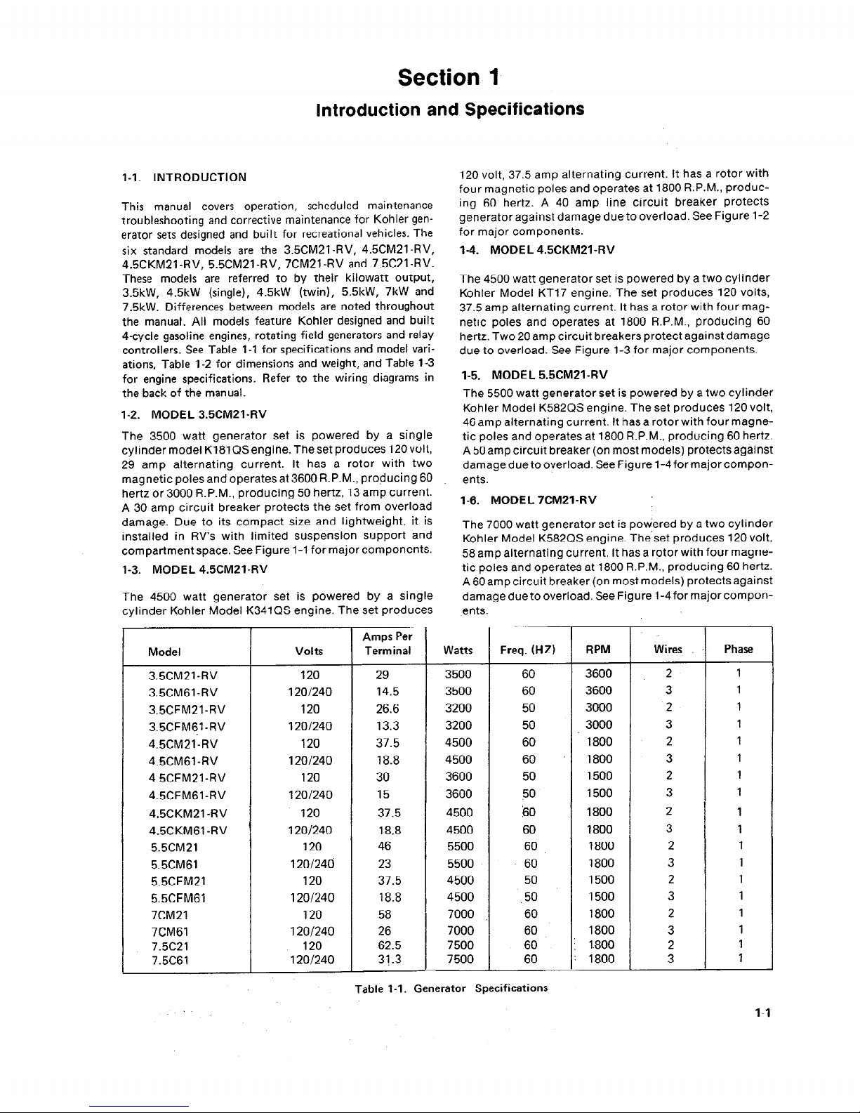
I-2. MODEL 3.5CM21-RV
The 3500 watt generator set is powered by a single
cylinder model K181 QS engine. The set produces 120 volt,
29 amp alternating current. It has a rotor with two
magnetic poles and operates at 3600 R.P.M., producing 60
hertz or 3000 R.P.M., producing 50 hertz, 13 amp current.
A 30 amp circuit breaker protects the set from overload
damage. Due to its compact size and lightweight, it is
installed in RV’s with limited suspension support and
compartment space. See Figure l-l for major components.
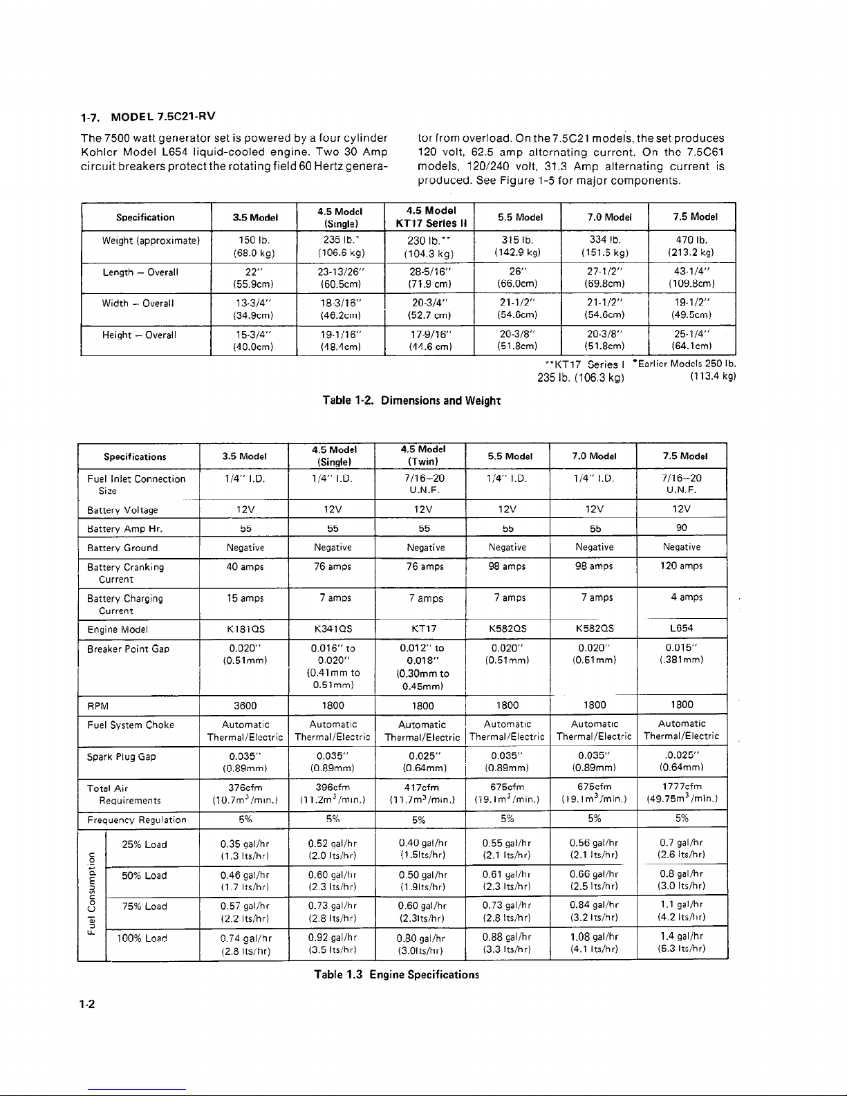
1-3. MODEL 4.5CM21-RV
The 4500 watt generator set is powered by a single
cylinder Kohler Model K341QS engine. The set produces
Model
3.5CM21-RV
3.5CM61-RV
3.5CFM21-RV
3.5CFM61-RV
4.5CM21:RV
4.5CM61 -RV
4.5CFM21-RV
4.5CFM61-RV
4.5CKM21 -RV
4.5CKM61 -RV
5.5CM21
5.5CM61
5.5CFM21
5.5CFM61
7CM21
7CM61
7.5C21
7.5C61
Volts
Amps Per
Term in al Watts Freq. (HZ) RPM
120
29
3500 60 3600
120/240
14.5 3500 60
3600
120
26.6
3200 50
3000
120/240
13.3
3200
50
3000
120
37.5 4500 60
1800
120/240 18.8
4500 60 *
1800
120
30
3600 50 1500
120/240
15
3600
SO
1500
120 37.5 4500 60
1800
1201240
18.8
4500 60
1800
120
46
5500 60
1800
120/246 23 5500 . 60 1800
120 37.5 4500 50 1500
120/240
18.8 4500 ,50 1500
120 58
7000 60 1800
120/240 26
7000
60 ’ 1800
120
62.5
7500
60 1.800
120/240
31.3 7500
60 1800
120 volt, 37.5 amp alternating current. It has a rotor with
four magnetic poles and operates at 1800 R.P.M., producing 60 hertz. A 40 amp line circuit breaker protects
generator against damage due to overload. See Figure l-2
for major components.
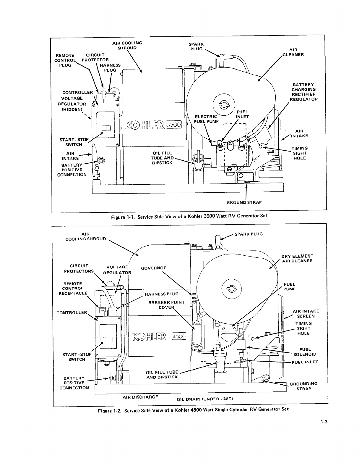
1-4. MODEL 4.5CKM21-RV
The 4500 watt generator set is powered by a two cylinder
Kohler Model KT17 engine. The set produces 120 volts,
37.5 amp alternating current. It has a rotor with four magnetic poles and operates at 1800 R.P.M., producing 60
hertz. Two 20 amp circuit breakers protect against damage
due to overload. See Figure l-3 for major components.
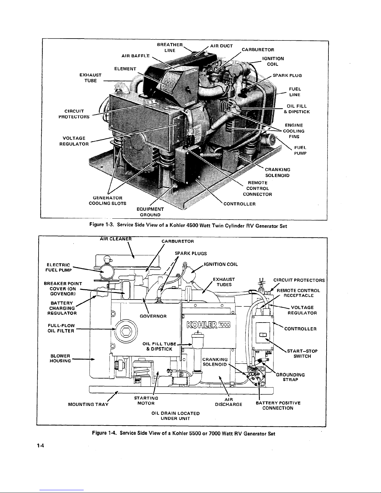
1-5. MODEL 5.5CM21-RV
The 5500 watt generator set is powered by a two cylinder
Kohler Model K582QS engine. The set produces 120 volt,
46 amp alternating current. It has a rotor with four magne-
tic poles and operates at 1800 R.P.M., producing 60 hertz.
A 50 amp circuit breaker (on most models) protects against
damage due to overload. See Figure I-4for major components.
1-6. MODEL 7CM21-RV
The 7000 watt generator set is powdered by a two cylinder
Kohler Model K582QS engine. The’set produces 120 volt,
58 amp alternating current. It has a rotor with four magnetic poles and operates at 1800 R.P.M., producing 60 hertz.
A 60amp circuit breaker (on most models) protects against
damage due to overload. See Figure I-4for major components.
. .
Wires, I
2
3
‘2
3
2
3
2
3
2
3
2
3
2
3
2
3
2
3
Phase
1
1
1
1
1
1
1
1
1
1
1
1
1
1
1
1
1
1
Table l-l. Generator Specifications
l-l
Page 6
1-7. MODEL 7.5CZl-RV
The 7500 watt generator set is powered by a four cylinder
Kohler Model L654 liquid-cooled engine. Two 30 Amp
circuit breakers protect the rotating field 60 Hertz genera-
torfrom overload. On the 7.X21 model-s, the set produces
120 volt, 62.5 amp alternating current. On the 7.5661
models, 120/240 volt, 31.3 Amp alternating current is
produced. See Figure 1-5 for major components.
Specification
Weight (approximate)
3.5 Model
150 lb.
(68.0 kg)
4.5 Model
(Single)
235 lb.*
(106.6 kg)
,
4.5 Model
KT17
Series II
5.5 Model 7.0 Model
7.5 Model
4
230 lb.**
315 lb. 334 lb.
470 lb.
(104.3 kg)
(142.9 kg)
(151.5 kg) (213.2 kg)
Length - Overall 22” 23- 13/26”
28-5/l 6”
26”
27-l/2”
43-l /4”
(55.9cm)
(60.5cm) (71.9 cm)
(66.Ocm)
(69.8cm) (109.8cm)
Width - Overall 13-3/4” 18-3/l 6” 1 20-3/4” 21-l/2”
(34.9cm) (46.2cm) 1 (52.7 cm)
(54.6cm)
Height - Overall 15-314” 19-l /I 6” 17-9/l 6”
20-3/8”
20-3/8” 25-l /4”
(40.0cm) (48.4cm) (44.6 cm)
(51.8cm)
(51.8cm) (64.1cm)
A
A
**KT17 Series I
*Earlier Models 250 I b.
235 lb. (106.3 kg)
(113.4 kg)
Table l-2. Dimensions and Weight
Specifications
Fuel Inlet Connection
Size
Battery Voltage
Battery Amp Hr.
Battery Ground
Battery Cranking
Current
3.5 Model
l/4” I.D.
12v
55
Negative
40 amps
4.5 Model
(Single)
l/4” I.D.
12v
55
Negative
76 amps
4.5 Model
(Twin)
7/l 6-20
U.N.F.
12v
55
Negative
76 amps
5.5 Model 7.0 Model
l/4” I.D. l/4” I.D.
12v
12v
55
55
Negative Negative
98 amps 98 amps
.
7.5 Model
7/l 6-20
U.N.F.
12v
90
Negative
120 amps
Battery Charging
Current
15 amps
7 amps
7 amps
7 amps 7 amps 4 amps
Engine Model
K181QS K34 1 QS KTI 7 K582QS K582QS L654
Breaker Point Gap
0.020” 0.016” to 0.012” to
0.020” 0.020” 0.015”
(0.51 mm)
0.020”
0.018”
(0.51 mm) (0.51 mm)
(.381mm)
(0.41 mm to
(0.30mm to
0.51 mm)
0.45mm)
RPM
3600 1800
1800
1800
1800
1800
Fuel System Choke
Automatic
Automatic
Automatic
Automatic Automatic
Automatic
Thermal/Electric Thermal/Electric Thermal/Electric Thermal./Electric Thermal/Electric Thermal/Electric
Spark Plug Gap
0.035” 0.035”
0 -025”
0.035” 0.035” .0.025”
(0.89mm)
(0.89mm)
(0.64mm) (0.89mm) (0.89mm)
(0.64mm)
Total Air
376cfm
396cfm
417cfm
675cfm
675cfm 1777cfm
Requirements ( 10.7m3/min.)
(11 .2m3/min.) (11 .7m3/min.) (19.1m3/min.)
(19.1 m3/min.) (49.75m3/min.)
Frequency Regulation
5% 5%
5%
5%
5% 5%
25% Load 0.35 gal/hr
0.52 gal/hr
0.40 gal/hr
0.55 gal/hr 0.56 gal/hr
0.7 gal/hr
g
(1.3 lts/hr) (2.0 lts/hr)
(1.5lts/hr)
(2.1 lts/hr)
(2.1 lts/hr)
(2.6 lts/hr)
._
‘;
5
50% Load
0.46 gal/hr 0.60 gal/hr
0.50 gal/hr
0.61 gal/hr
0.66 gal/hr 0.8 gal/hr
(1.7 lts/hr) (2.3 lts/hr)
(1 .9lts/hr)
(2.3 lts/hr)
(2.5 lts/hr)
(3.0 lts/hr)
v)
c
s
75% Load 0.57 gal/hr
0.73 gal/hr
0.60 gal/hr
0.73 gal/hr 0.84 gal/hr
1.1 gal/hr
z
(2.2 lts/hr) (2.8 lts/hr) (2.3lts/hr)
(2.8 lts/hr)
(3.2 Its/h r)
(4.2 Its/hr)
l? .
100% Load
0.74 gal/hr
0.92 gal/hr
0.80 gal/hr
0.88 gal/hr 1.08 gal/hr
1.4 gal/hr
I I
(2.8 Itslhr) I
(3.5 Its/hr)
I
(3.0lts/hr) I
(3.3 lts/hr) ,
(4.1 lts/hr) ,
(5.3 lts/hr) ,
Table 1.3 Engine Specifications
1-2
Page 7
AIR COOLING
SPARK
SHROUD
REMOTE
CIRCUIT
CL
CONTROL PROTECTOR
CONTROLLER
(HIDDEN) I
INTAKE
BATTERY -+@ /
POSITIVE
CONNECTION
GROUND STRAP
AIR
EANER
BATTERY
CHARGING
RECTIFIER
REGULATOR
INTAKE
TIMING
SIGHT
HOLE
Figure 1-1. Service Side View of a Kohler 3500 Watt RV Generator Set
AIR
COOLING SHROUD
SPARK PLUG
DRY ELEMENT
AIR CLEANER
CIRCUIT
GOVERNOR
_
PROTECTORS\
REGULAT(
REMOTE
CONTROL
EC EPTAC L
iONTROLLER
START-STOP
SWITCH
BATTERY
POSITIVE
CONNECTION
I
STRAP
HARNESS PLUG
BREAKER POINT
FUEL
PUMP
AIR INTAKE
/ SCREEN
TIMING
SIGHT
HOLE
OIL FILL TUBE
AND DIPSTICK
,
AIR DISCHARGE
0lL DRAIN (UNDER UNIT)
Figure l-2. Service Side View of a Kohler 4500 Watt Single Cylinder RV Generator Set
Page 8
BREATHER_
AIR DUCT
/
IGNITION
thtMtNT
EXHAUST
.d
~.
TUBE
..”
FUEL
LINE
i OIL FILL
CIRCUIT
?OTECTOR
FINS
VOLTAGE /
EGULATOR
c
&j \ FUEL
PUMP
COOLING SLOTS
/
EQUIPMENT
GROUND
$p”
.:’ ,::. : ,, :.:::::,A~
:i:::::
,:*.
r
“’ :
./: >::: ;,.. 1’
,;:z>
. . .
..,,,,,.
’ CONTROLLER
Figure 1-3. Service Side View of a Kohler 4500 Watt Twin Cylinder RV Generator Set
AIR CLEANER
.
CARBURETOR
UST
ES
CIRCUIT PROTECTORS
/
b=AA9TE CONTROL
ICEPTACLE
BREAKER POINT
COVER (ON
GOVENOR)
BATTERY
CHARGING
VOLTAGE
REGULATOR
GOVERNOR
EGULATOR
FULL-FLOW
OIL FILTER
CONTROLLER
OIL FILL TUBE
& DIPSTICK
‘OP
BLOWER
, Ah I I
HOUSING
/
SWITCH
GROUNDING
AIR
I
“ISCHARGE
BATTERY POSITIVE
Y
CONNECTION
MOUNTI
OIL DRAIN LOCATED
UNDER UNIT
Figure I-4. Service Side View of a Kohler 5500 or 7000 Watt RV Generator Set
I-4
Page 9
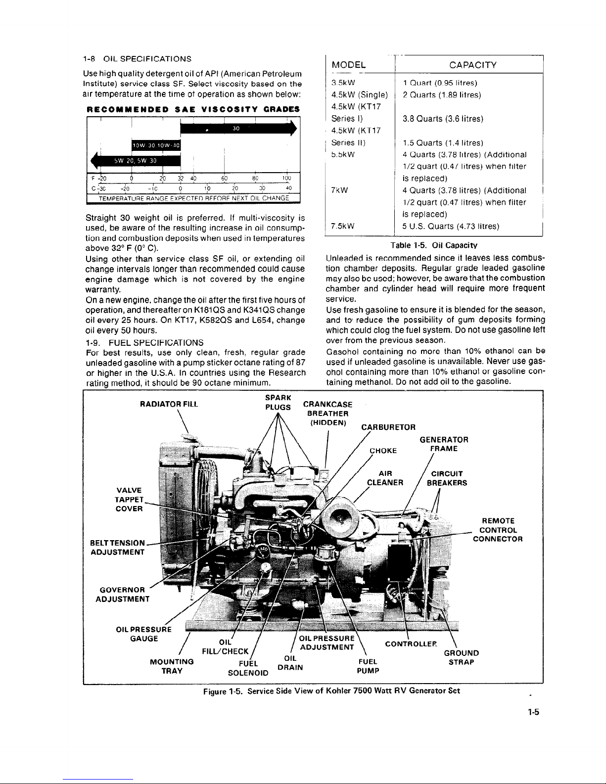
l-8 OIL SPECIFICATIONS
Use high quality detergent oil of API (American Petroleum
Institute) service class SF. Select viscosity based on the
air temperature at the time of operation as shown below:
RECOMMENDED SAE VISCOSITY GRADES
!
I
I
I
I
I 1 I
'F -50 6
T 1 r I I
20
32 40 60 80 100
t
I I
T
I
I I
I
c-30 -20 -10
0 10 20 30 40
TEMPERATURE RANGE EXPECTED BEFORE NEXT OIL CHANGE
l
Straight 30 weight oil is preferred. If multi-viscosity is
used, be aware of the resulting increase in oil consumption and combustion deposits when used in temperatures
above 32’ F (0” C).
I
Using other than service class SF oil, or extending oil
change intervals longer than recommended could cause
engine damage which is not covered by the engine
warranty.
On a new engine, change the oil after the first five hours of
operation, and thereafter on K181QS and K341 QS change
oil every 25 hours. On KT17, K582QS and L654, change
oil every 50 hours.
I-9. FUEL SPECIFICATIONS
For best results, use only clean, fresh, regular grade
unleaded gasoline with a pump sticker octane rating of 87
or higher in the U.S.A. In countries using the Research
MODEL
CAPACITY
35kW
1 Quart (0.95 Iitres)
4.5kW (Single)
2 Quarts (1.89 litres)
4.5kW (KT17
Series I)
3.8 Quarts (3.6 litres)
4.5kW (KT17
Series II)
1.5 Quarts (1.4 litres)
5.5kW
4 Quarts (3.78 litres) (Additional
l/2 quart (0.47 litres) when filter
is replaced)
7kW
4 Quarts (3.78 litres) (Additional
l/2 quart (0.47 litres) when filter
is replaced)
7.5kW
5 U.S. Quarts (4.73 Iitres)
Unleaded is recommended since it leaves less combus-
tion chamber deposits. Regular grade leaded gasoline
may also be used; however, be aware that the combustion
chamber and cylinder head will require more frequent
service.
Use fresh gasoline to ensure it is blended for the season,
and to’ reduce the possibility of gum deposits forming
which could clog the fuel system. Do not use gasoline left
over from the previous season.
Gasohol containing no more than 10% ethanol can be
used if unleaded gasoline is unavailable. Never use gas-
ohol containing more than 10% ethanol or gasoline con-
Table 1-5. Oil Capacity
rating method, it should be 90 octane minimum.
taining methanol. Do not add oil to the gasoline.
RADIATOR FILL
\
SPARK
PLUGS
CRANKCASE
A
BREATHER
\ /I\\
(HIDDEN)
I
CIjRBURETOR
VALVE
TAPPET,
COVER
BELTTENSION
ADJUSTMENT
GOVERNOR
ADJUSTMEN
OIL PRE
GAUGE
/
/
OIL
FILL/CHECK
MOUNTING
I /
OIL PRESSURE
ADJUSTMENT
\
\
CONTROLLER
\
GROUN
FUEL
OIL
FUEL
DRAIN
STRAF
TRAY
SOLENOID
PUMP
C
REMO’
CONTR
:ONNEC
TE
OL
TOR
Figure 1-5. Service Side View of Kohler 7500 Watt RV Generator Set
c
l-5
Page 10
Section 2
Operation
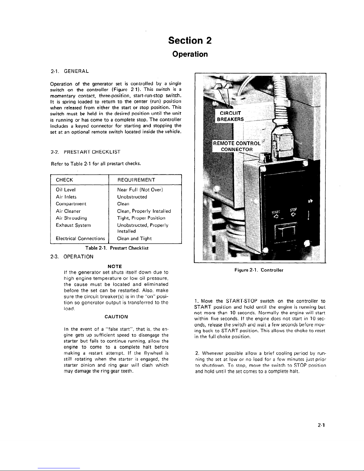
2-l. GENERAL
Operation of the generator set is controlled by a single
switch on the controller (Figure 2-l). This switch is a
momentary contact, three-position, start-run-stop switch.
It is spring loaded to return to the center (run) position
when released from either the start or stop position. This
switch must be held in the desired position until the unit
is running or has come to a complete stop. The controller
includes a keyed connector for starting and stopping the
set at an optional remote switch located inside the vehicle.
2-2. PRESTART CHECKLIST
Refer to Table 2-l for all prestart checks.
CHECK REQUIREMENT
Oil Level Near Full (Not Over)
Air Inlets Unobstructed
Compartment Clean
Air Cleaner Clean, Properly Installed
Air Shrouding
Tight, Proper Position
Exhaust System Unobstructed, Properly
lnstal led
Electrical Connections Clean and Tight
Table 2-I. Prestart Checklist
2-3. OPERATION
NOTE
If the generator set shuts itself down due to
high engine temperature or low oil pressure,
the cause must be located and eliminated
before the set can be restarted. Also, make
sure the circuit breaker(s) is in the “on” position so generator output is transferred to the
load.
CAUTION
In the event of a “false start”, that is, the engine gets up sufficient speed to disengage the
starter but fails to continue running, allow the
engine to come to a complete halt before
making a restart attempt. If the flywheel is
still rotating when the starter is engaged, the
starter pinion and ring gear will clash which
may damage the ring gear teeth.
Figure 2-I. Controller
‘I. Move the START-STOP switch on the controller to
START position and hold until the engine is running but
not more than 10 seconds. Normally the engine will start
within five seconds. If the engine does not start in 10 seconds, release the switch and wait a few seconds before moving back to START position. This allows the choke to reset
in the full choke position.
2. Whenever possible allow a brief cooling period by running the set at low or no load for a few minutes just prior
to shutdown. To stop, move the switch to STOP position
and hold until the set comes to a complete halt.
2-I
Page 11
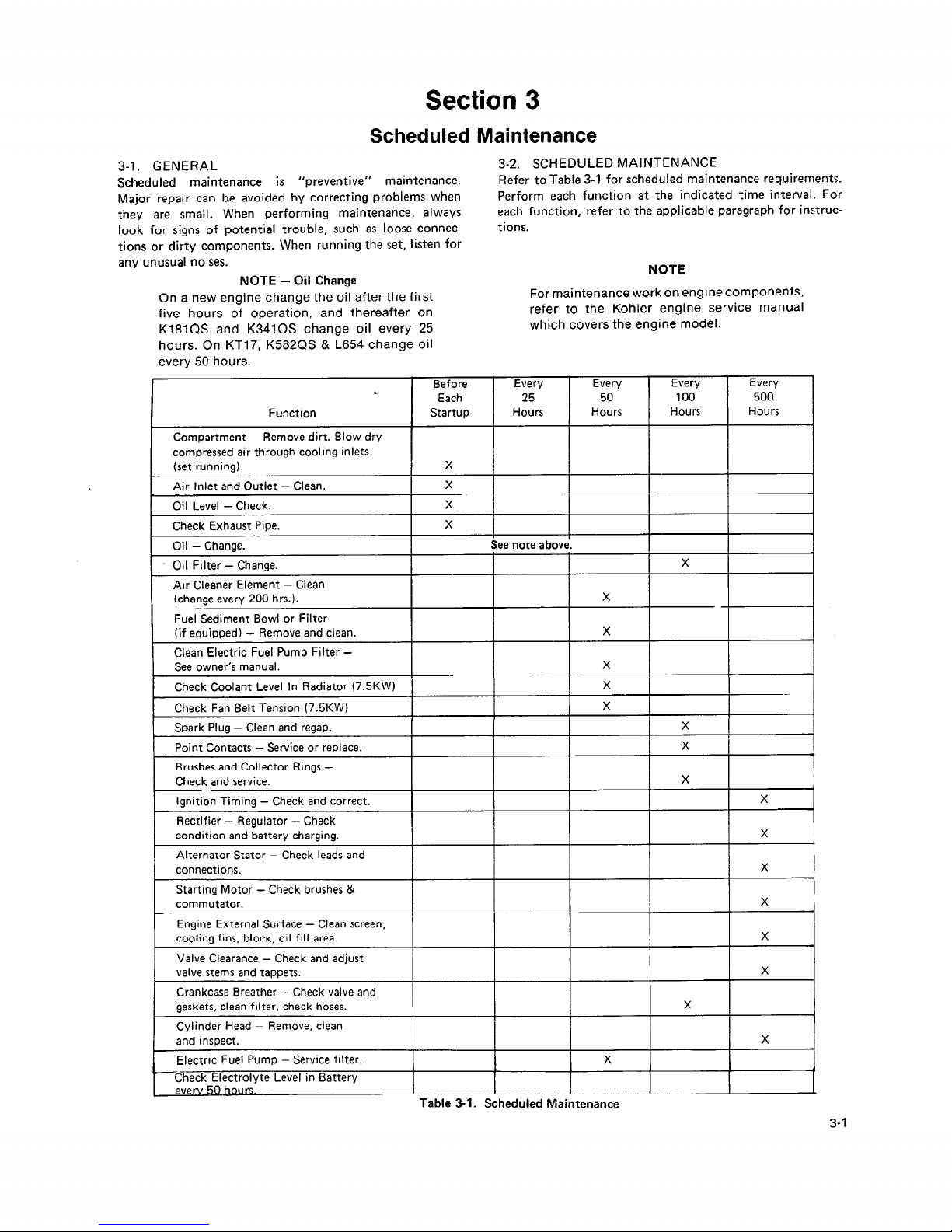
Section 3
Scheduled Maintenance
3-l. GENERAL
Scheduled maintenance is “preventive” maintenance.
Major repair can be avoided by correcting problems when
they are small. When performing maintenance, always
look for signs of potential trouble, such as loose connections or dirty components. When running the set, listen for
any unusual noises.
NOTE - Oil Change
3-2. SCHEDULED MAINTENANCE
Refer to Table 3-1 for scheduled maintenance requirements.
Perform each function at the indicated time interval. For
each function, refer to the applicable paragraph for instructions.
NOTE
On a new engine change the oil after the first
five hours of operation, and thereafter on
K181QS and K341QS change oil every 25
hours. On KT17, K582QS & L654 change oil
every 50 hours.
For maintenance work on engine components,
refer to the Kohler engine service manual
which covers the engine model.
Every
1
Before Every Every Every
.
Each
25 50
100 500
Function Startup Hours
Hours Hours Hours
.
Compartment - Remove dirt. Blow dry
compressed air through cooling inlets
(set running).
X
I
Air Inlet and Outlet - Clean.
X
Oil Level - Check.
X
Check Exhaust Pipe. X
I
Oil - Change.
See note above.
. Oil Filter - Change.
X
Air Cleaner Element - Clean
(change every 200 hrs.).
X
Fuel Sediment Bowl or Filter
(if equipped) - Remove and clean.
X
Clean Electric Fuel Pump Filter See owner’s manual.
X
Check Coolant Level In Radiator (7.5KW) X
Check Fan Belt Tension (7.5KW)
X
Spark Plug - Clean and regap.
X
Point Contacts - Service or replace.
X
Brushes and Collector Rings Check and service.
X
Ignition Timing -
Check and correct.
X
Rectifier
- Regulator - Check
condition and battery charging.
X
Alternator Stator - Check leads and
connections. X
Starting Motor - Check brushes &
commutator.
X
Engine External Surface - Clean screen,
cooling fins, block, oil fill area.
X
Valve Clearance
- Check and adjust
valve stems and tappets. X
I
Crankcase Breather - Check valve and
gaskets, clean filter, check hoses.
X
Cylinder Head - Remove, clean
and inspect.
X
.
Electric Fuel Pump - Service filter.
X
1-i: 50 hours.
Check Electrolyte Level in Battery
---_--.-_ . ..-_ _
Table 3-1. Scheduled Maintenance
3-1
Page 12
Section 4
Troubleshooting
4-l. GENERAL
CAUTION
When troubleshooting a generator set, always consider the
simplest causes first. Narrow the problem down to a functional system, such as fuel or ignition. To operate efficiently, an engine must have sufficient fuel, a good ignition
spark and good compression. All adjustments must be
correct. For a generator to produce the required electricity,
all parts must be clean, all connections tight, and all components in working order. See Table 4-l for Engine Troubleshooting and Table 4-2 for Generator Troubleshooting.
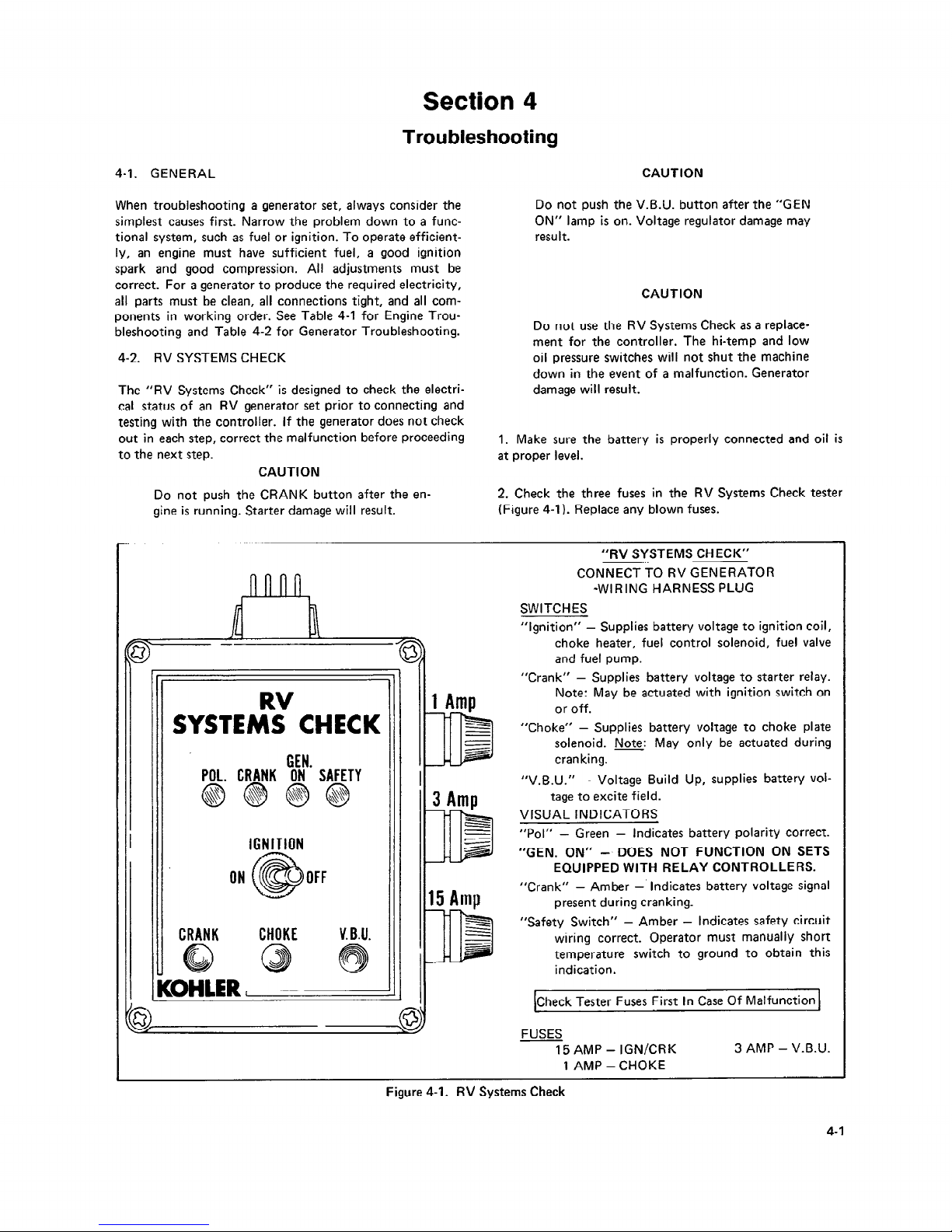
4-2. RV SYSTEMS CHECK
The “RV Systems Check” is designed to check the electrical status of an RV generator set prior to connecting and
testing with the controller. If the generator does not check
out in each step, correct the malfunction before proceeding
to the next step.
Do not push the V.B.U. button after the “GEN
ON” lamp is on. Voltage regulator damage may
resu It.
CAUTION
Do not use the RV Systems Check as a replacement for the controller. The hi-temp and low
oil pressure switches will not shut the machine
down in the event of a malfunction. Generator
damage will result.
1. Make sure the battery is properly connected and oil is
at proper level.
CAUTION
Do not push the CRANK button after the en-
2. Check the three fuses in the RV Systems Check tester
gine is running. Starter damage will result.
(Figure 4-l). Replace any blown fuses.
RV
‘II I
SYSTEMS CHECK
GEN
POL. CRANK ON’ SAFETY
IGNITION
ON OFF
CRANK CHOKE
V. B.U.
“RV SYSTEMS CHECK”
CONNECT TO RV GENERATOR
*WIRING HARNESS PLUG
SWITCHES
“Ignition” -
Supplies battery voltage to ignition coil,
choke heater, fuel control solenoid, fuel valve
and fuel pump.
“Crank” -
Supplies battery voltage to starter relay.
Note: May be actuated with ignition switch on
or off.
“Choke” - Supplies battery voltage to choke plate
solenoid. Note: May only be actuated during
cranking.
“V.B.U.” -
Voltage Build Up, supplies battery vol-
tage to excite field.
VISUAL INDICATORS
“Pol” - Green -
Indicates battery polarity correct.
“GEN. ON” -. DOES NOT FUNCTION ON SETS
EQUIPPED WITH RELAY CONTROLLERS.
“Crank” - Amber -’
Indicates battery voltage signal
present during cranking.
“Safety Switch” - Amber - Indicates safety circuit
wiring correct. Operator must manually short
temperature switch to ground to obtain this
indication.
[Check Tester Fuses First In Case Of Malfunction 1
FUSES
15 AMP - IGN/CRK
1 AMP -CHOKE
3 AMP - V.B.U.
Figure 4-1. RV Systems Check
4-1
Page 13
3. Remove the
12 pin connector
plug it into the
tester.
from the controller and NOTE
4. Observe the POL (polarity) lamp. Green light indicates
battery polarity is correct. If lamp does not light, check for
correct battery connection to the generator set.
NOTE
On 5.5kW, 7kW and 7.5kW sets the SAFETY
lamp will also be on. This indicates the low oil
pressure switch is functioning properly.
5. With the IGNITION switch in OFF position, press the
CRANK button. The CRANK lamp should light and the
engine should crank. If the lamp does not light, no voltage
from the battery is present.
On 5.5kW, 7kW and 7.5kW sets, the SAFETY
lamp will go off after the engine has reached
sufficient operating oil pressure.
IO. To check the high temperature cutout, low oil pressure
cutout and/or the oil level cutout for proper operation,
start the generator set and connect a jumper wire from the
cutout device to ground. The “amber” safety lamp should
light, indicating the protective circuit is functioning properly.
11. If all checks are OK, connect the 12 pin connector to
the generator set controller.
If the 15 amp fuse blows, check for defective cranking
solenoid, fuel pump or fuel solenoid, ignition coil, choke
heater, fuel shutdown control or shorted wiring.
6. Remove the air cleaner cover to observe the choke plate
during the next step.
If the 1 amp fuse blows, check for defective choke solenoid or wiring.
7. Again, with the IGNITION switch in OFF position press
the crank button. While the engine is cranking, press the
CHOKE button to supply battery voltage to the choke
plate solenoid. Make sure the choke plate is functioning
properly. If not, see Section 7. Release the CRANK and
CHOKE buttons.
If the 3 amp fuse blows, check for shorted or grounded
generator rotor or defective voltage regulator.
8. With the IGNITION switch ON, start the engine, using
CRANK and CHOKE buttons as needed. If engine does not
start, see Engine Troubleshooting, Table 4-l. With engine
at operating speed, press V.B.U. (voltage build-up) button
momentarily. Check for generator output voltage. If no
output voltage is available, see Troubleshooting Generator., Table 4-2.
9. Turn the IGNITION switch to OFF position to stop the
engine.
4-3. TROUBLESHOOTING
Refer to Table 4-l for engine troubleshooting. To make
engine repairs, refer to the Kohler engine service manual
which covers the engine model. A troubleshooting chart
cannot cover every possible cause of malfunction. Always
consider every possible cause of malfunction. Knowledge
of four cycle engines and battery ignition systems can
be applied. Refer to Table 4-2 to troubleshoot the generator. The table refers to applicable paragraphs in the manual.
4-2
Page 14
CONDITION
A. Hard Starting or Loss of Power
B. Overheating
C. Backfiring
D.
Occasional “skip” at High Speed
E. Operating Erratically
POSSIBLE CAUSE
1. Faulty Ignition.
a. Loose or grounded high tension or breaker point leads.
b. Improper breaker point gap and timing.
c. Defective breaker points.
d. Faulty spark plug or improper gap.
e. Faulty condenser or coil.
f. Weak battery.
2. Faulty Fuel System.
a. Gasoline not getting to carburetor.
A. Dirt or gum in fuel line.
B. Fuel pump faulty.
b. Dirt in carburetor.
c. Carburetor improperly adjusted.
d. Choke faulty or improperly adjusted.
e. Stale fuel.
f. Carbon build up.
g. Possible intake manifold vacuum leak.
3. Valve maintenance.
4. Defective Automatic Compression Release (ACR).
1.
2.
3.
4.
5.
6.
7.
8.
9.
10.
11.
12.
Insufficient available cool air.
Dirty air intake screen, shroud or cooling fins.
Stale fuel.
Fuel mixture too lean.
Improper ignition timing.
Engine overloaded.
Tight tappet clearance.
Insufficient hot-air discharge opening.
Loose or broken fan belt (7.5kW).
Low coolant level (7.5kW).
Too much lube oil.
Summer/Winter air baffle in wrong position.
‘I. Fuel mixture too lean.
2. Improper timing.
3. Valve “sticking”.
4. Possible intake manifold vacuum leak.
1. Spark plug gap too wide.
2. Improper carburetor setting or lack of fuel.
3. Wrong type spark plug. Use resistor type plug.
4. Improper timing.
5. Faulty condenser.
1:
2.
3.
4.
5.
6.
7.
8.
9.
IO.
Clogged fuel line.
Water in fuel.
Faulty choke control.
Improper fuel mixture.
Loose ignition connections.
Vacuum leaks in manifold or carburetor connection.
Vent in gas cap plugged.
Fuel pump faulty.
4CR installed upside down. Solenoid should be to the bottom.
Improper ground on anti-dieseling device.
Table 4-1. Engine Troubleshooting
Refer to Kohler Engine Service Manual for Repair.
defer to Generator Owner’s Manual for Adjustments.
4-3
Page 15

CONDITION
1. Engine will not crank.
POSSIBLE CAUSE/CORRECTION (SECTION)
1. Battery cable connections reversed. (Must be negative ground.)
2. 10 amp fuse in controller blown (5-3).
3. Defective start switch or “C” relay (5-2).
4. Open circuit in wiring harness or connector.
5. Faulty starter motor.
6. Open circuit in REI diode (5-4).
7. Normally closed 3CR contacts, open (5-5).
8. Busted or loose ground strap.
2. Engine cranks but will not start.
1. Choke not operating or out of adjustment (7-1, 7-2).
2. Check fuel supply to carburetor.
3. Faulty fuel shut-down control (7-3).
4. Faulty fuel pump.
5. Dirty or stuck ignition points.
6. Faulty condenser.
7. Faulty spark plug.
3. Engine starts, then stops when
switch is closed.
8. 2CR relay not functioning. Must have battery voltage on positive
connection of ignition coil (5-5).
9. Fuel mixture. Replace.
1. No AC generator output.
2. Faulty 3CR interlock relay (5-5).
3. Faulty 4CR voltage sensing relay (5-5).
4. Faulty exciter voltage regulator (6-7).
4. No AC output.
1. Circuit breakers in the off position (2-3).
2. Generator brushes not making contact on slip rings (6-5).
3. Faulty build-up circuit. Battery voltage must be present at terminal
“B” of regulator during cranking (6-7).
4. Open connection in wiring harness or plug connector (5-2).
5. Faulty exciter voltage regulator (6-7).
6. Circuit protector tripping due to overload, reduce load.
5. Low output or excessive drop in
voltage (below 1 IO volts).
1. Generator set overloaded.
2. Engine rpm set too low (7-5 thru 7-9).
3. Faulty exciter voltage regulator (6-7).
4. Poor stator coil connections, use a clamp-on ammeter and check
each connection. .
6. High AC voltage (above 125 volts AC).
1. Faulty exciter voltage regulator.
2. Stator reconnected improperly.
7. Engine shuts down for no apparent
reason.
1. Generator set overheated
- improper installation. Refer to RV
installation manual or 75kW Owner’s Manual.
2. No fuel.
3. Oil level or oil pressure system failure.
4. Faulty shutdown solenoid.
8. Unit will not operate with remote
switch - OK at controller.
I. Incorrect wiring of remote switch to remote plug assembly. Center
pole of remote switch must connect to terminal 4 of remote harness
plug, Figure 5-2.
2. Open connection in wiring.
Table 4-2. Troubleshooting Generator
Page 16

Section 5
Relay Controller
5-I. DESCRIPTION
All generator set functions are dependent upon the control-
ler. See Figure 5-l for parts identification. For operation
instructions refer to Section 2. The controller includes a
keyed connector for installing a remote switch and hourmeter panel. This optional remote switch allows the operator to start and stop the generator set from another location in the vehicle. The hourmeter records the hours of
generator set operation (Figure 5-2). The controller can be
removed by removing the two snap connectors and two
capscrews underneath the controller. This section covers
sequence of operation, and fuse, diode, and relay replacement.
5-2. SEQUENCE OF OPERATION
The Relay Controller is the controlling point for generator
set operation. The following is the sequence of operations
controlled by the Relay Controller. See Figures 5-3
through 5-7.
.
REMOTE CONTROL
/
WIRING HARNESS
CONNECTOR
PLUG
IGNITION RELAY
REI
3CR
DIODE INTERLOCK RELAY
Figure 5-1. Controller
12 VOLT
GENERATOR
“ON” LIGHT
12 VOLT
HOURMETER
Lead Designation
. .
Pin No. Color Gauge of Wire
1 Red
18
2 White
22
3 Brown
22
4 Black
18
5
6 Blue
22
REMOTE CONTROL CONNECTOR
(ON CONTROLLER)
HARNESS
/
PLUG
SPRING LOADED
START-STOP
APPLIES TO SWITCH A-269299 ONLY
KOHLER PART NO. PA-269966
Figure 5-2. Remote Control Connections
5-l
Page 17
l lO AMP
lN.LINE
FUSE
I
CHOKE HTR.
ZCR
I I
*EARLIER MODELS ONLY
238760
\;/-
.
d
2CR
8 /
*EARLIER MODELS ONLY
238749
Figure 5-3. Sequence of Operation
Schematic 3.5kW
Figure 5-4. Sequence of Operation
Schematic 4.5kW (Single)
52
Page 18
5 II
-STARTER 1
REuOTE SW.
+
YLL
2CR
2 + ICN -
EINTS
OIL
e
II
LIITLUI I
BREAKER
4
“EARLIER MODELS ONLY
277948
STD. ON 7kW
OPTION 5.5kW
. :
Q%. Qb +O-.
.
I, 1
.
.
*EARLIER MODELS ONLY
277931
Figure 5-5. Sequence of Operation
Schematic 4SkW (KT17 Series I)
Figure 5-6. Sequence of Operation
Schematic 5.5 & 7kW
5-3
Page 19

I2 VOLT
3CRT
La?-
FUEL ‘PUMP
.
I
TRANSFORMER
Y
r
CEN:: ATOR
i t
L2 LI
LO
“EARLIER MODELS ONLY
241753
Figure 5-7. Sequence of Operation
Schematic 7.5kW
1. Pressing the start-stop switch to the start position energizes both the cranking contactor “C” and the 2CR relay.
(Diode REI will prevent this from happening if the battery
is connected in reverse.)
5-4
2. Energizing the 2CR relay will allow current to flow
through the 10 Amp in-line fuse to the ignition coil, choke
heater, carburetor shut-down solenoid and electric fuel
pump (if equipped).
3. Energizing cranking contactor “C” will allow current to
flow to the starter motor and crank the engine. The carburetor choke solenoid will also be energized and current
can flow through the normally closed 4CR contacts to the
“B” terminal of the aenerator voltage regulator for the
initial voltage build-up.
4. When the engine starts and the generator is producing
AC output, the 4CR relay (mounted in the generator end
bracket) will energize.
5. The normally CLOSED contacts in the V.B.U. (voltage
. .
bui,ld-up) circuit will then open and disconnect the battery
supply from the generator voltage regulator.
6. The normally OPEN 4CR contacts will close and allow
the 3CR relay to become energized. All the 3CR contacts
will then change positions, the normally open contacts
will close and the normally closed contacts will open.
7. The normally closed 3CR contacts in series with the
“C” cranking contactor will open deenergizing the “C”
contactor. This offers protection from engaging the starter
motor while the unit is operating.
8. The 3CR contacts in series with the 2CR relay coil will
close, maintaining current flow to the 2CR relay coil.
The 2CR relay controls current flow to the engine ignition
circuit.
9. The now closed 3CR contacts in series with the ICR
relay coil and engine safety cutouts will allow the ICR relay
to become energized if the safety cutout contacts close.
The ICR relay also energizes when the start-stop switch is
placed in the stop position.
10. Energizing the ICR relay, either by the engine safety
cutouts or by placing the start-stop switch to the stop position will disrupt current flow to the 2CR relay coil and in
turn prevent current flow to the ignition circuit when the
2CR contacts in this circuit open.
5-3. FUSES
A
WARNING
UNIT STARTS WITHOUT NOTICE! To prevent accidental
starting on units with a remote start/stop switch, always
disconnect battery (remove negative lead first and reconnect it last) to disable generator set before working on any
equipment connected to generator.
There is one IO Amp fuse inside the controller (Figure 5-l).
This fuse protects the controller against damage in the
event a short develops in the engine wiring. If this fuse
“blows” the set will stop. If the set has stopped due to
causes other than lack of fuel, engine malfunction, or low
oil pressure, remove the cover of the controller and check
the fuse. If blown, replace the fuse then attempt to restart
the generator set. If the set will not start, or if the fuse
blows again, locate and correct the cause.
Page 20

NOTE
On earlier models a 10 Amp fuse is mounted inline between the controller and ignition coil.
See the wiring diagram, It protects the control-
ler in the event of a shorted or failed ignition
coil, fuel pump, choke heater, shut-down control or engine wiring.
NOTE
If the 10 Amp in-line fuse is blown the engine
will not crank. If the 10 Amp fuse inside the
controller is blown the engine will crank but
not start. If either fuse blows while the engine
is running, the set will stop.
NOTE
On 4.5 (twin) & 7.5kW models, a self-resetting
circuit breaker located in the generator end
bracket protects the battery charging circuit.
The 7.5kW model uses an 8 Amp circuit breaker. The 4.5kW (twin) and early 7.5kW models
5-5. RELAYS
There are four relays in the generator set. One relay is lo-
cated in the generator end bracket (Figure 6-7). The other
three relays are mounted inside the controller. Refer to
Figure 5-8 when checking or replacing relays. The function
of each relay is described below.
. ICR (STOP RELAY)
- When energized, deenergizes
the 2CR relay.
l 2CR (IGNITION RELAY) - When energized, pro-
vides battery supply to the engine electrical system.
l 3CR (INTERLOCK RELAY) - When energized, de-
energizes the
“C” cranking contactor, and provides
current to energize the ICR relay upon closing of the
engine safety cutouts.
l 4CR (VOLTAGE SENSING RELAY) - When ener-
gized, disconnects excitation current from battery to
regulator and field (V.B.U.), and energizes the 3CR
relay. (The 4CR relay is located inside the generator
end bracket.)
use a 5 Amp circuit breaker.
5-4. REl DIODE
A diode is located in-line between
the start-stop switch and
the 2CR relay to protect against
reverse battery polarity.
When replacing the diode, make
certain connections are
made with the arrow on the diode directing away from the
start-stop switch (Figure 5-8).
STARTING 1 RUNNING 1 STOPPING
“C” contactor
energized
2CR relay
energized
4CR relay
energized
3CR relay
energized
2CR relay
energized
’ 1CR relay
energized
5-5
Page 21

THE SCHEMATIC BELOW SERVES AS
A GUIDE TO LOCATING PROPER
TERMINAL CONNECTIONS.
CONTROLLER
- COVER
0 0
TERMINAL CONNECTIONS AS
SHOWN ON WIRING DIAGRAM
0 0
I
START
STOP
SWITCH
CONNECTORS SHOWN
FROM PIN INSERTION
SIDE
-lr
r
I
c
I
I
I
IO AMP FUSE
I
I
I
I
I
I
I
I
I
I
---
l
I
I
I
I
!
I I
1
I
I
I
I
I
I
I
I
I
I
I
I
.I
I
-m-----
~~~~~~--~~-----~
LOCAL CONTROL BOX A-241752 COVER
(SHOW FROM RcAR)
277947
I
I
I
I
I
I
.I
I
~~~~,~~~ w-&-w------
- - - - - LOCAL CONTROL 801 A-241939
--e,u#
WUCR
&W@J fROu RUR)
277932
Figure 5-8. Relay Terminal Connections
Page 22

Section 6
Generator
6-1. GENERAL
This chapter covers disassembly, inspection, and testing of
the generator components. See Figures 6-l and 6-2 for
parts identification.
grounded. Never touch electrical leadi or appliances with
wet hands, when standing in water, or on wet ground as
the chance of electrocution is especially prevalent under
such conditions.
6-2. TROUBLESHOOTING
6-3. GENERATOR DISASSEMBLY
Refer to Table 4-2 to troubleshoot the generator. Follow
the disassembly procedure in Section 6-3 as far as necessary
to inspect a component, then start reassembly procedure in
Section 6-12 at the point the component is replaced, When
a fuse must be replaced, always inspect the related components and wiring to locate the cause. Refer to the wiring
diagrams in the back of the manual,
A
WARNING
HIGH VOLTAGE! Remember that the function of a generator set is to produce electricity and that wherever
electricity is present, there is the potential danger of
electrocution. Take the same precautions with electrical
appliances in your coach that you would observe in your
home. Keep away from electrical circuits and wiring while
the set is running and have electrical service performed
only by qualified electricians. Make sure unqualified
persons, especially children, cannot gain access to your
set-keep the compartment door locked or securely
latched at all times. Be sure that generator is properly
NOTE
Tag leads to ease re-installation. Scratch align-
ing marks on parts before removing to aid
reassembly.
7. Disconnect battery of generator set, negative lead first.
2. Disconnect the generator ground strap at the tray (Figgure 6-3 or 6-4). On the 3.5kW and 4.5kW (single), remove
the battery positive lead from the generator positive stud
and remove stud remove stud from the generator mounting.
3. Remove the center panel (4.5, 5.5, 7, 7.5kW), see Figure 6-5; or remove the end panel (3.5kW), see Figure 6-6.
4. Remove the plug from the voltage sensing relay Figure
6-7). The relay can now be removed.
‘j 12b
1. End Bracket
7. Panel, Center
12b. Voltage Regulator (7.5KW) 18. Ball Bearing
2. Stator 8.
Circuit Breaker(s)
13. Voltage Sensing Relay (VSR) 19. Washer
3. Rotor
9. Junction Panel
14. Thru Bolt 20. Tolerance Ring
4. Adapter
IO. Generator Fan
15. Over Bolt
21. Brush
5. Guard, Fan 11. Bearing Cap
16.
End Bracket
22. Brush Holder
6. Junction Panel
12a. Voltage Regulator (3.5kW-7kW)
17. Slip Ring
Figure 6-l.
Generator, Cross Sectional View
6-1
Page 23

3
2 \
13
1
I --.- /
16-
19’ i?y-
1.
2.
3.
4.
5.
6.
7.
8.
9. Ball Bearing
10.
Slip Ring
Voltage Sensing Relay
(VSR)
Wiring Harness
Spring
Brush
Brush Holder
Panel
Tolerance Ring
Rotor (2 Pole Shown)
11.
Fan
12.
Adapter
13.
Stator
14. End Bracket
15.
Exciter / Voltage Regulator
16.
Circuit Breaker
17. Transformer
18. Transformer Bracket
19. Circuit Breaker
20. Bridge Rectifier
Figure 6-2. Generator Pa
,:::; GROUND STRAF
Figure 6-3. Generator Ground Strap (3.5kW Shown)
Figure 6-4. Generator Ground Strap
(4.5 Twin, 5.5, 7, 7.5kW)
es Identification
Figure 6-5. Center Panel Removal (4.5, 5.5, 7, 7.5kW)
Figure 6-6. End Panel Removed (3.5kW)
6-2
Page 24

Figure 6-7. Removing Plug from Voltage
Sensing Relay (VSR) (4.5kW-7kW)
5. Remove the top housing (Figure 6-8) (3.5 and 4.5kW
single).
6. Remove the exhaust tube (Figure 6-9) (3.5kW-7kW).
7. Remove the side housings (3.5kW-7kW).
8. Remove the inside housings (Figure 6-10) (3.5 and 4.5
kW single).
9. Loosen the vibro-mounts (Figure 6-11) and lift the gen-
erator from the base.
10. Tilt the generator end up and place blocks under the
generator adapter.
Figure 6-9. Exhaust Tube
Figure 6-10. Inside Housing Removal
Figure 6-8. Top Housing Removal
Figure 6-l I. Vibro-Mounts
6-3
Page 25

Figure 6-13. Over Bolt Removal (Two Shown)
11. Lift the brushes by the leads and lock in this position
by inserting a retainer wire as shown in Figure 6-12.
12. Remove the end bracket by removing four long over
bolts. See Figure 6-13.
13. Disconnect the stator leads from the regulator.
NOTE
The voltage regulators on 4.5, 5.5, 7 and 7.5kW
generator sets are located inside the end bracket.
On the 3.5kW, the voltage regulator is located
outside the end bracket. See Figures 6-14 and
6-15. Terminal connections and testing will be
the same for all.
Figure 6-14. Exciter / Voltage Regulator
Figure 6-15. Exciter / Voltage Regulator (3.5KW)
14. The stator (Figure 6-16) can be tested at this time (Sec-
tion 6-8). Remove the stator by guiding it to the rear,
15.1 l Four-Pole Removal (4.5, 5.5,7,7.5kW). Remove thru
bolt and detach washers. Re-insert thru bolt leaving a l/8
6-4
Page 26

inch gap between bolt and rotor. Bump the thru bolt with
a lead mallet to break the rotor loose (4.5, 5.5, 7, 7.5kW
only) for removal (Figure 6-l 7). If the bearing turns freely
and has no sign of damage do not remove, the fan will be
removed with rotor (Figure 6-18).
NOTE
On 7.5kW, if the rotor seems loose but can not
be removed, see Section 6-3.2.
Figure 6-16. Stator
Figure 6-17. Rotor Thru Bolt
15.2. Two-Pole Removal (3.5kW). On the 3.5kW, the rotor
is held to the engine crankshaft by right-hand threads on
the crankshaft and in the rotor shaft (engine rotates counterclockwise when viewed from drive side). These threads
have been coated with antiseize compound to aid disassembly. To remove rotor, place a wood block in a trailing edge
of one rotor pole. A sharp, medium force hammer blow to
wood block’s end will free the rotor, allowing it to be
turned off by hand (Figure 6-19).
Figure 6-18. Removing Rotor (4.5,5.5, 7kW)
CAUTION
Do not attempt to remove rotor by blocking
engine cooling fan and turning rotor with any
kind of wrench. Damage to fan blades and rotor
may result.
Figure 6-19. Removing Rotor (3.5kW)
6-5
Page 27

Figure 6-20. Removing Oil Tank
Figure 6-21. Oil Tank Removed
6-3.1. Removal of Oil Tank 4.5kW (KT17 Series I only)
1. Drain oil from oil tank assembly.
2. Detach nut from eyebolt. Remove the bolt attaching the
oil tank to engine leg. Detach ventilation line (Figure 6-20).
3. Pull the tank off, making sure it is removed squarely
(Figure 6-21).
4. Oil Level Switch Replacement. (If the oil level switch
does not need replacement, omit Step 4.)
a. Remove oil tank cover by removing six screws. Be
careful not to damage gasket surface when prying
apart.
b. Remove switch at coupling connection. It will be
necessary to cutoff eyelet terminal and insulink to
remove switch.
c. Apply pipe thread compound to new switch, slide
leads through insulator sleeve and thread switch into
coupling. Tighten switch so that distance between
bottom of switch and inside of cover is 3.0 in. (76.2mm).
See Figure 6-22.
6-6
Insulator
Sleeve
YL-J
Notch Must Be
On Bottom
Figure 6-22. Oil Level Switch Mounting
d. With gasket surfaces clean, install oil tank cover
using a new gasket. Torque bolts to 70 in/lbs. (7.9Nm)
using torque sequence shown in Figure 6-23.
NOTE
Cut one wire from switch so that it reaches
screw shown in Figure 6-23, strip 250 in.
(6.4mm) of insulation and crimp-on l/4” eyelet term inal. Place terminal between lockwasher
and cover.
e. Plug end of ventilation fitting. Below compressed air,
about 30 psi (207kPa), into oil tank bore and check for
leaks at gasket surfaces, switch connection and ventilation fitting using a soap solution. Repair any leaks.
CAUTION
Any air leak in the ventilation line system could
cause the engine oil to be drawn from the reservoir into the crankcase, resulting in engine blowby and a low oil level shutdown.
f. Cut the other wire from switch so that it reaches #I2
(purple) lead, strip .250 in. (6.4mm) of insulation and
connect together using an insulink.
.+
w
\
Ground
Lead
Figure 6-23. Torque Sequence
Page 28

5. When installing the oil tank, make sure O-rings are not
damaged. Apply grease to the O-rings, fitting and the oil
tank bore. Push tank on squarely.
6-3.2 On the 7.5kW generator set, if the rotor seems loose
but cannot be removed, the flywheel has become free of
the crankshaft taper. To separate rotor from flywheel,
adapter, and stub shaft proceed as follows.
I. Remove eight bolts fastening generator adapter to bell
housing (Figure 6-24).
2. Pull rotor, adapter, and flywheel away from engine.
3. Slide adapter over generator fan as far as possible.
4. Remove four bolts fastening stub shaft to flywheel
(Figure 6-25).
Figure 6-24. Adapter Removal
Stub
Flywheel
Figure 6-25. Separating Stub Shaft and Flywheel
5. The flywheel and adapter can now be removed (Figure
6-26).
6. Strike downward on corner of stub shaft with a lead
mallet as shown in Figure 6-27.
7. The stub shaft can now be removed.
- .
Figure 6-26. Remove Flywheel and Adapter
Figure 6-27. Stub Shaft Removal
6-4. BUI LD-UP Cl RCUIT
This circuit magnetizes the rotor during cranking. When
the switch on the controller is moved to the start position,
6-7
Page 29

DC current flows from the battery to brushes and sl
on the rotor. See Figure 6-28.
ip rings
6-5. BRUSHES
6-5.1 General. The brushes transfer current from the voltage regulator to slip rings. The brushes carry a very low cur-
rent (approximately 2 Amps) and should last the life of the
generator set. Abrasive dust on the slip rings could, however, shorten the life of the brushes. Excessive arcing at the
brushes could damage the voltage regulator. Arcing could
be caused by weak springs, damaged slip rings, sticking
brushes, loose holder, or poor brush alignment.
6-5.2. Maintenance.
1. Remove the end bracket panel to gain access to the
brushes.
2. The brushes must be free to move within the holder and
held in proper contact by the springs. When properly
positioned, spring pressure on the brush surface will
cause the brush to wear evenly. Figure 6-29 shows normal
brush wear.
3. Replace the brushes if worn excessively or unevenly.
4. Replace the springs if damaged or discolored.
5. Be sure to use original or identical l/2 inch (12.7mm)
screws when reinstalling the brush holder. Longer screws
will break the holder when tightened.
6. To install the brushes and holder insert a wire as shown
in Figure 6-30, to hold the brushes in. Position the brushes
on the slip rings and install the two screws. Remove the
wire.
CAUTION
If the retainer wire is not removed, the voltage
regulator will be damaged when the generator
is started.
Figure 6-29. Brushes
WIRE
Figure 6-30. Brush Holder
STARTER
GENERATOR
ROTOR
/
BRUSHES &
SLIP RINGS
4CR
GENERATOR
REGULATOR
12 VOLT
BATTERY
Figure 6-28. Buildup Circuit
6-8
Page 30

6-6. SLIP RINGS
Slip rings acquire a glossy brown finish in normal operation.
Do not attempt to maintain a bright, newly-machined appearance. Ordinary cleaning with a dry, lint free cloth is
usually sufficient. Very fine sandpaper (#OO) may be used
to remove roughness. Use light pressure on the sandpaper.
Do not use emery or Carborundum‘ paper or cloth. Clean
out all carbon dust from the generator. If the rings are
black or pitted, remove the rotor and remove some of the
surface material by using a lathe.
6-7. EXCITER / VOLTAGE REGULATOR
6-7.1. General. The voltage regulator assembly (Figure
6-31) includes a bridge rectifier and a voltage regulating
circuit. AC from the stator is received at the “AC” terminals on the regulator. Thi’s current is rectified to DC by the
bridge rectifier and supplied to the rotor from terminals
(+) and (-) through the brushes and slip rings. This AC is
constantly monitored by the regulator to maintain +2%
variation of the stator output.
NOTE
Although the physical appearance of your
voltage regulator may differ from the one pictured, its fu tiction is identical.
NOTE
When replacing regulators apply a light coating
of thermal compound between the regulator
and end bracket. This compound aids in dissipating heat from regulator to end bracket. For
regulators with two mounting screws tighten to
20 in. Ibs. (2.3Nm) maximum. For center
mount-type regulators, tighten screw to 15 in.
Ibs. (1.7Nm) maximum.
67.2. Exciter / Voltage Regulator Test.
A
’ WARNING
HIGH VOLTAGE! Remember that the function of a gen-
erator set is to produce electricity and that wherever
electricity is present, there is the potential danger of
electrocution. Take the same precautions with electrical
appliances in your coach that you would observe in your
home. Keep away from electrical circuits and wiring while
the set is running and have electrical service performed
only by qualified electricians. Make sure unqualified
persons, especially children, cannot gain access to your
set-keep the compartment door Iock,ed or securely
latched at all times. Be sure that generator is properly
grounded. Never touch electrical leads or appliances with
wet hands, when standing in water, or on wet ground as
the chance of electrocution is especially prevalent under
such conditions.
Since this test is designed for use in the field, it only
checks regulator output when “cold” and does not check
voltage build-up.
Figure 6-31. Exciter / Voltage Regulator
To complete the test you’ll need the following equipment:
Two 12OV/lOO watt bulbs and sockets.
11 O/l 20V AC power source or variable transformer.
Switch, PST, 12OV, 2 Amp. minimum
Fuse, 2A (in holder)
Jumpers
Multimeter
Figure 6-32 shows the typical voltage regulator terminal
identification:
OR
AC
0
+
AC
Figure 6-32. Terminal Identification
6-9
Page 31

1. Connect two 100 watt light bulbs across “+” and ‘I-”
terminals of regulator. See Figure 6-33.
NOTE
2. Set multimeter range to 100 Volts DC. Connect meter
across light bulbs. Check for correct polarity (refer to
Figure 6-33).
A
WARNING
HIGH VOLTAGE! Remember that the function of a gen-
erator set is to produce electricity and that wherever
electricity is present, there is the potential danger of
electrocution. Take the same precautions with electrical
appliances in your coach that you would observe in your
home. Keep away from electrical circuits and wiring while
the set is running and have electrical service performed
only by qualified electricians. Make sure unqualified
persons, especially children, cannot gain access to your
set-keep the compartment door locked or securely
latched at all times. Be sure that generator is properly
grounded. Never touch electrical leads or appliances with
wet hands, when standing in water, or on wet ground as
the chance of electrocution is especially prevalent under
such conditions.
3. Completely disconnect IZOV AC source from primary
power source before connecting across regulator.
A
WARNING
HIGH VOLTAGE! When the power cord is plugged in
during voltage regulator test, the AC pins become “hot”
and there is danger of electrocution.
4. Connect one pole of (on-off) switch and the fuse to one
of the “AC” terminals on the regulator. Connect other pole
of switch to the 110/l 20 AC source (Figure 6-33). Connect
other “AC” terminal to 110/12OV AC source.
5. Turn on 1 IO/l 20V AC source.
6. With multimeter connected across light bulbs, turn on
switch. Bulbs should light immediately, DC voltmeter
should register 10 to 50V DC.
If bulbs flash momentarily and extinguish,
flicker dimly or glow steadily the regulator is
functioning properly.
These conditions are
caused by the amplitude of the “AC” supply
voltage used. A momentary flash results when
supply voltage is above the regulating voltage
or regulator under test. Flickering results when
supply voltage and regulating voltage are with-
in a few volts. If a variable transformer is
available, it should be used to adjust the AC
supply ‘until the bulbs glow steadily. The variable transformer will adjust the voltage to coincide with the approximate regulating voltage of
the regulator.
7. Test field build-up circuit by connecting one end of
jumper to either “AC” terminal. Touch the other end of
jumper to “B” terminal. Bulbs should glow brighter. Volt-
meter should indicate 50-75 Volts DC.
A
WARNING
HIGH VOLTAGE! When the power cord is plugged in
during voltage regulator test, the AC pins become “hot”
and there is danger of electrocution.
NOTE
If voltage readings coincide with above recom-
mended test results, regulator may be used in
generator set.
CAUTION
Completely disconnect IZOV AC source from
primary power
source before disconnecting
from regulator.
Fl
2A
110/120 AC B
+
VAC OR
VARIABLE
TRANSFORMER’+
* See Note After Step 7.
Figure 6-33. Wiring Diagram -Voltage Regulator Field Test
6-10
Page 32

Figure 6-34. Stator
6-8. STAT0 R
6-8.1. General. The stator (Figure 6-34) consists of a series
of coils of wire laid in a laminated steel frame. The stator
leads (see Generator Wiring Diagram) supply voltage to the
AC load and exciter / voltage regulator.
6-8.2. Testing. The stator should have 0.25 ohms resistance
across each winding. To test, connect an ohmmeter between
leads 1 and 2, 3 and 4, and then 33 and 44. The leads are
tagged with the lead number,
6-9. ROTOR
The function of the rotor is to create a magnetic field. The
3.5kW has a rotor with two electromagnetic field poles
(Figure 6-35). The +5kW, 55kW, 7kW and 7.5kW each
have a rotor with four electromagnetic field poles (Figure
6-36). Rotor resistance readings are given in Table 6-1.
Measure resistance (ohms) between the two slip rings.
c
s
l
MODEL
RESISTANCE
3.5KW 9 to 11 ohms
4.5KW 8 to 10 ohms
5.5KW 8 to 10 ohms
7KW 8 to 10 ohms.
Table 6-l. Rotor Resistance
6-10. SEPARATE FIELD EXCITATION
As a preliminary aid to troubleshooting, the generator field
(rotor) may be excited (magnetized) using an outside power
source and the following procedure:
1. Disconnect brush leads from voltage regulator.
Figure 6-35. Two Pole Rotor
.:
Figure 6-36. Four Pole Rotor
A
WARNING
DANGEROUS ACID! Avoid contact with battery electro-
lyte. It contains acid which can eat holes in clothing, burn
skin, and cause permanent damage to eyes. Always wear
splash-proof safety goggles when working around the
battery. If battery electrolyte is splashed in the eyes or on
skin, immediately flush the affected area for 15 minutes
with large quantities of clean water. In the case of eye
contact, seek immediate medical aid. Never add acid to a
battery once the battery has been placed in service. Doing
so may result in dangerous spattering of electrolyte.
A
WARNING
EXPLOSIVE BATTERY GASES! The gases generated by a
battery being charged are highly explosive. Do not smoke
or permit flame or spark to occur near a battery at any
time, particularly when it is being charged. Avoid contacting terminals with tools, etc., to prevent burns and to
prevent sparks that could cause an explosion. Remove
wristwatch, rings, and any other jewelry before handling
battery. Any compartment containing batteries should be
well ventilated to prevent accumulation of explosive gases.
To avoid sparks, do not disturb battery charger connections while battery is being charged and always turn
charger off before disconnecting battery connections.
Turn automotive test equipment off when connecting or
removing battery clips. When removing or reconnecting
battery cables, make sure ignition switch and all accessories are turned off.
6-11
Page 33

2. Connect brush leads in series with 12-Volt battery and
DC ammeter as shown in Figure 6-37.
3. Ammeter reading should approximate battery voltage
divided by specified rotor resistance (Table 6-1).
4. Record ammeter reading.
5. Start generator set and run at NO load.
6. Observe ammeter with unit running. If current increases
considerably, a running short in the rotor has been detected.
EXCITER /
VOLTAGE r 1
REGULATOR ,-‘&I;
DC
BATTERY
SLIP RINGS J BRUSHES
Figure 6-37. Separate Excitation Connections
6-l 1. VOLTAGE SENSING RELAY
erator output, and disconnect excitation current from the
battery to the regulator and field (V.B.U.), and energize the
3CR (interlock relay). If there is no AC output; the relay
will not energize, and the unit will shut down when the
start-stop switch is released from the start position.
6-12. GENERATOR REASSEMBLY
1. On the 3.5kW, apply antiseize compound to the rotor
threads (Figure 6-39). Thread the rotor onto the drive
shaft, and tighten by hand.
2. On the 4SkW, 55kW, 7kW or 7.5kW, apply antiseize
compound to the crankshaft stub (Figure 6-40). Install the
rotor onto the crankshaft with the thru bolt. See Table 6-2
for torque value.
I
SIZE
I
TORQUE
I
5116
3/8
l/2
100 to 125 in. Ibs. (11.3-14.1Nm)
175 to 200 in. Ibs. (19.8-22.6Nm)
40 to 55 ft. Ibs. (54.2-74.6Nm)
Table 6-2. Generator Thru Bolt Torque
3. Slide the stator into position making sure the leads are
at 12 o’clock position (Figure 6-41).
4. Install the end bracket with the four long over bolts.
5. Position the brush holder and install the two brush
holder screws. To install the brush holder, it will be
The voltage sensing relay (Figure 6-38) is located in the
necessary to retain the brushes with a wire (Figure 6-42).
end bracket assembly. Its function is to sense AC gen-
Remove the wire when the brushes are installed.
’ TO PIN “4” OF
PI CONNECTOR
TO LEAD FROM “B”
TERMINAL OF
VOLTAGE REGULATOR
I
I
COIL RESISTANCE = 4000 OHMS
COIL VOLTAGE = 120 VOLTS AC
Figure 6-38. Generator Voltage Sensing Relay (VSR)
6-12
Page 34

).A:::‘; ::,..:, :,<4y:.:
,. ..::
THREADS
Figure 6-39. Rotor (3.5kW)
6. Install the generator to the base.
Figure 6-41. Stator and Rotor
Figure 6-42. Brush Retaining Wire
Figure 6-40. Driveshaft (4.5kW Shown)
7. Install the exhaust tube. Install the side housings and
top housing.
8. Install the voltage sensing relay and plug. See Generator Wiring Diagram for connections.
9. Install the circuit breaker(s) and end panels (Figures
6-43 and 6-44).
10. Reconnect the generator ground strap to the tray, On
the 3.5kW and 4.5kW (single), reinstall the generator posi-
tive stud and reconnect battery positive lead to stud.
11. Reconnect battery of generator set, negative lead last.
6-13
Page 35

.A..
.: ,...
Figure 6-43. End Bracket, Panels Removed (4.5kW Single Shown)
BREAKER :
Figure 6-44. Lower End Bracket (4.5 Twin, 7SkW)
6-14
Page 36

Section 7
Choke, Shutdown Control and Governor
7-1. CHOKE TESTING AND ADJUSTMENTS (3.5kW,
4.5kW SINGLE)
A
WARNING
BACKFIRE! A sudden backfire can cause serious burns.
Keep hands and face away from the carburetor when the
air cleaner is removed.
7-1.1
General. When the engine start switch is activated,
battery current activates the rotary solenoid in the electric
choke unit (Figure 7-l). The choke lever pushes the choke
plate into the full choke position. The solenoid deenergizes
immediately after the switch is released from the start posi-
tion. When the solenoid deenergizes, the choke plate opens
to a position determined by a thermostatic spring and the
ambient temperature. As the engine warms and less choking
is needed, the thermistor circuit allows the choke plate to
gradually move to full open position.
A
WARNING
UNINTENTIONAL STARTING! To prevent accidental
starting when checking choke operation, remove spark
plug lead(s) at spark plug(s).
A
WARNING
FLASH FIRE! Asudden flash fire can cause serious burns.
To avoid the possibility of a flash fire, do not smoke or
permit flame or spark to occur near carburetor, fuel line,
fuel filter, fuel pump, or other potential sources of spilled
fuel or fuel vapors.
7-1.2. Inspection.
1. Disconnect the high tension lead from the spark plug
so the engine will not start.
2. Remove the air cleaner cover, element and base plate.
3. Push the start-stop switch on the controller to the start
position and hold for five seconds. The choke plate should
CHOKE
SHAFT
/
ONE LEAD TO
STARTER RELAY
THE OTHER LEAD
TO CONTROLLER
HEATER
(THERMISTOR)
TERMINAL
LOCKWASHER
IDLE FUEL
ADJUSTMENT
SOLENOID
TABS
AUTOMATIC
ELECTRI-CHOKE UNIT
I
LEVER
l/2 TURN TENSION
SPRING
Figure 7-1. Choke and Carburetor (3.5KW, 4.5KW)
7-l
Page 37

close a minimum of 45’ at an ambient temperature of
about 75’F (24’C). The plate will close more at lower tem-
peratures. The choke plate should open when the switch is
released.
, , 4; During cranking the choke will remain closed as long as
t the start-stop switch is held in the start position.
5. If the choke does not function properly, refer to Choke
Troubleshooting, Table 7-l.
7-l .3. Testing - Choke Solenoid (3.5,4.5kW Single)
1. Disconnect leads from the solenoid tabs (Figure 7-l).
2. Check the resistance of the solenoid by connecting an
ohmmeter or multimeter across the solenoid tabs. Solenoid resistance should be approximately 23 ohms or
higher.
7-1.4. Testing - Choke Heater (3.5,4.5kW Single)
1. Remove the lead from the heater terminal.
2. Check heater resistance. Connect one lead of an ohm-
meter or multimeter to the heater terminal. Connect the
other lead to the carburetor body (ground).
3. The resistance should read at least three ohms. If not,
replace the choke.
7-1.5. Replacement and Adiustment.
NOTE
When installing the choke, make sure the choke
plate arm goes under the choke lever.
1. Position the choke with the two mounting screws
slightly loose.
2. Push the choke unit all the way down, then, keeping
slight pressure on it, move the chokeplate (in carburetor)
into the full open position allowing the choke unit to rise.
3. Rotate the choke unit clockwise (viewed from choke
side) with a slight pressure. Continue to rotate the choke
until it can no longer be rotated without closing the choke
plate. (An internal spring will be wound up in the last 5 to
15 degrees of rotation before internal stop is reached).
4. When the choke plate is full open, tighten the bracket
screws and install the three leads.
5. Check choke function by removing the spark plug lead
and cranking the engine.
The choke plate should close
a minimum of 45’ at a temperature of about 75’F (24’C).
The plate will close more at lower temperatures. The choke
will remain closed as long as the start-stop switch is held in
the start position.
PROBLEM
Choke won’t close when
cranking.
CAUSES
SOLUTIONS
1. Faulty lead wires or terminals.
1. Change lead wires or replace choke.
2. Air cleaner gasket interference with 2. Reposition flat of gasket to provide
choke shaft lever. (4.5kW only.)
clearance for choke shaft lever.
3. Faulty solenoid.
3. Test solenoid.
4. Faulty controller or ground
4. Replace lead to controller with
in controller.
a jumper wire to ground. If choke
functions properly check controller.
5. Choke lever lacks sufficient travel
5. Manually move the choke lever until
or smooth movement.
the choke plate is fully closed. Replace the choke unit if it does not
move freely.
Choke will not fully open.
1. Choke spring not properly
adjusted.
2. Choke shaft fails to move freely.
3. Faulty choke adjustment.
4. Faulty heater.
1. Remove spring retainer and with
choke wide open wind up spring l/2
turn, replace spring retainer.
2. Replace choke shaft.
3. Adjust choke.
4. Test heater resistance.
Table 7-1. Troubleshooting Choke (3.5KW, 4.5KW)
7-2
Page 38

7-2, CHOKE TESTING AND ADJUSTMENTS (4.5 TWIN,
5.5, 7, 7.5kW)
7-2.1. General. The choke on the 4.5 (twin), 5.5, 7 and
7.5kW models is an intergral part of the carburetor. The
choke wit1 close automatically from ambient air. Upon
starting, the engine vacuum will partially open the choke.
The bi-metal spring in the choke is e&trically connected to
the ignition coil and the current flowing thrbugh the bimetal spring will heat to a point that the choke will open
fully.
7-2.2. Inspection.
1. Disconnect the high tension leads from spark plugs so
the engine will not start.
2. Remove the air cleaner cover, element and base plate.
3. Push the start switch on the controller to the start position and hold for five seconds. The choke should fully close
and release when the start switch is released.
Figure 7-2. Choke (4.5 Twin, 5..5,7,7.5 kW)
4. If the choke does not function properly (Step 3), see
troubleshooting, Table 7-2.
7-2.3. Adjustment. The choke unit (Figure 7-2) is set at
the factory for average conditions. To readjust for local
conditions, loosen the cover retaining screws and shift the
cover in clockwise direction for richer setting or counterclockwise direction for leaner setting. Tighten the cover
retainer screws.
start position, battery current thru the solenoid holds the
plunger and continues to hold it while the engine is running. When the switch is moved to the stop position the
solenoid de-energizes and drops the plunger into a porting
in the carburetor to stop all flow of fuel.
7-3.2. Inspection and Repair.
1. Make sure the solenoid has a secure electrical connection
and good contact with the hold down bracket (ground).
7-3. POSITIVE SHUTDOWN CONTROL (3.5kW-7kW)
2. Check for stuck plunger. Replace if,.damaged.
7-3.1. General. If an engine has been working under load,
it tends to continue running or “diesel” after the switch is
moved to the stop position. This is prevented on these
generator sets by a solenoid and plunger which positively
stops all flow of fuel when the switch is moved to the stop
position. See Figure 7-I or Figure 7-3. The solenoid is
mounted on the carburetor. When the switch is in the
3. Check for defective solenoid with an ohmmeter or multimeter. Solenoid resistance is approximately 20 ohms.
7-3.3. Temporary Field Fix.
1. Turn the main fuel adjusting needle out then shift the
solenoid retaining bracket.
PROBLEMS
Choke won’t close during
cranking.
Choke will not4ully open.
CAUSES
Faulty lead to choke.
Fau
ty lead to ground.
PO0 r
s adjustment.
SOLUTlONS
1.
2.
1.
2.
1.
2.
Check for secure lead connections
Make continuity check on lead. Re-
place if no continuity.
Check for secure lead connections.
Make continuity check on lead. Re-
place if no continuity.
Adjust choke.
Repair with kit or replace choke.
1. Poor adjustment.
2. Faulty choke.
1. Adjust choke.
2. Repair with kit or replace choke.
Table 7-2. Troubleshooting Choke (4.5 Twin, 5.5, 7, 7.5kW)
7-3
Page 39

Figure 7-3. Shutdown Control Solenoid (3.5kW-7kW)
2. Lift the solenoid and remove the plunger.
3. Replace the solenoid and retaining bracket and
the main fuel needle. (See Carburetor Adjustment).
readjust
7-4. CRANKCASE BREATHER (3.5kW, 4.5kW)
7-4.1. General. Reed type breathers are used to maintain a
slight vacuum in the crankcase. A clogged or pinched crankcase breather, or faulty reed assembly can cause positive
pressures to build up in the crankcase resulting in unseating
of the dipstick and oil leakage thru the oil fill tube. See
Figure 7-4, 7-5 or 7-6.
STUD
FILTER
GASKET
\
,
VALVE COVER
Figure 7-4. Crankcase Breather Assembly (3.5kW)
7-5. GOVERNOR (3.5kW, 4.5kW)
7-5.1. General. All Kohler Single Cylinder Engines are
equipped with centrifugal flyweight mechanical type gov-
BREATHER PLATE
VALVE COVER
COVER GASKET
BREATHER
HOSE
Figure 7-5. Crankcase Breather Assembly (4.5kW Single)
COVER GASKET
BREATHER PLATE
GASKET -
Figure 7-6. Breather Assembly (4.5kW Twin)
ernors. The governor gear flyweight mechanism is mounted
within the crankcase and driven off a gear on the camshaft.
In operation,
centrifugal force causes the flyweights to
move outward with increase in speed and inward with decreasing speed. As the flyweights move outward, they force
the rod portion of the assembly to push outward. Tension
of the governor spring pulls the flyweights back inward
with decrease in engine speed. The rod, in turn, contacts
a tab on the governor cross shaft causing it to rotate with
changing speed. One end of the cross shaft protrudes thru
the side of the crankcase. Thru external linkage, the action
of the cross shaft is transmitted to the throttle (or butterfly) valve in the carburetor. When the engine is at rest, the
tension of the governor spring should hold the throttle
valve in open position.
7-4
Page 40

7-5.2. Adjustments. The governor maintains engine speed
when changing loads and limits the engine speed. Initial
adjustment is made at the factory and should not be required in the field unless the linkage works loose or becomes disconnected. Speed adjustment should be made if the
engine surges when changing loads or if speed drops considerably when a normal load is applied.
A. Initial Governor Adjustment (Figure 7-7 or 7-8).
1. With engine ‘stopped, loosen (do not remove) the arm
retaining nut which secures the governor arm to the cross
Figure 7-8.
Governor Components and Adjustment Points
(4.5kW Single)
Figure 7-7.
Governor Components and Adjustment Points (3.5kW)
2. Grasp the end of the shaft with pliers and turn the shaft
as far as possible in counterclockwise direction until the
internal tab on the shaft stops against the governor gear
mechanism.
Hold shaft in this position, pull governor
arm all the way from the carburetor then retighten the arm
retaining nut.
B. Governor Speed Adjustment.
1. If overspeed or underspeed condition is suspected, check
speed with a tachometer or frequency meter at rated load.
2. Loosen speed adjusting nuts to decrease speed and
tighten speed adjusting nuts to increase speed.
C. Sensitivity Adjustment. If the speed drops considerably
when a normal load is applied, the governor may not be
sensitive enough.
If speed surging occurs with changing
load, the governor may be too sensitive.
1. To make the governor MORE sensitive, increase the
spring tension by moving the spring hooks into holes spaced
further apart.
2. To make the governor LESS sensitive, decrease the
spring tension by moving the spring hooks into holes
spaced closer together.
7-6. GOVERNOR HUNTING CHECKS (4.5 kW SINGLE
ONLY).
Governor hunting is a periodic frequency variation. If the
variation (hunting) is audible to the unaided ear, it is not
acceptable. Use the checklist below to help maintain
proper governor operation. The items in this list may be
used singly or in combination to achieve smoothest pos-
sible operation.
NOTE
Due to variances in generator output wave
shape, not all pointer type frequency meters are
compatible.
1. Set the point gap to 0.020 in. (0.51 mm) with a feeler
gauge and adjust the carburetor for peak performance.
2. With the engine not running check for free governor
linkage movement from idle to full throttle. (Note: Remove
excess paint from governor spring and dampening spring
and make sure choke wires do not interfere.)
3. With the engine shut down the throttle will be in wide
open position. Adjust the governor linkage so that approximately l/32” (0.79mm) space exists between the throttle
lever and carburetor body. (Note: This can be done by
sight, no fine measurement is necessary.)
7-5
Page 41

GOVERNOR
DAMPENING
IDLE STOP
SCRE
LINKAGE
\
CARBURETOR
BODY
/
Figure 7-10. Installing Air Intake Tube
(3.5kW, 4.5kW Single)
Figure 7-9. Carburetor (4.5kW Single)
4. Check idle speed, at no load, with the throttle lever
against the idle speed screw and set speed to approximately 1680 RPM (56 Hz).
5. Reposition the governor spring in the governor lever.
On most units the 2nd hole from the bottom provides the
best operation. Whenever the governor spring is moved in
the governor lever, the governor speed control must be
adjusted at no load, to approximately 1890 RPM (64 Hz).
6. If poor governing remains, the spring may be moved to
the bottom hole. If the governing is good but the speed
drop from no load to full load is too great (over 90 RPM
(3 Hz)) the governor spring can be moved up one hole in
the governor lever.
7. After making choke and governor adjustments reinstall
the air cleaner base. Thread the crankcase breather hose
back thru the hole in the base plate. Align the three small
holes with the threaded holes in the carburetor.
NOTE
When placing the base plate on the carburetor,
be sure to install the air intake tube into the
blower housing as shown in Figure 7-10 (long
side down).
7-7. GOVERNOR (4.5kW TWIN)
7-7.1. General. This model is equipped with a centrifugal
flyweight mechanical governor. The governor gear/flyweight mechanism is mounted within the crankcase and
driven off a gear on the camshaft.
7-7.2. Speed Adjustment. The throttle shaft is fixed at a
definite length to establish a load speed of 1800 RPM. Any
variation in speed frequency changes the output of the gen-
erator. For this reason only slight re-adjustment of speed is
possible. Proceed as follows:
1. First loosen the outside locking nut.
2. To increase speed, tighten the inside speed adjusting nut
to draw back the speed adjusting arm.
3. To d’;e’ccr”ease speed, loosen the speed adjusting nut.
4. Securenew setting by tightening outside locking nut.
7-7.3 Sensitivity Adjustment. If the governor is too sensitive, speed surging will occur with change in load. If the
governor is not sensitive enough, a big drop in speed will occur when normal load is applied.
1. To make the governor more sensitive, move the governor
*
spring in togards the governor shaft.
2. To make the governor less sensitive move the governor
spring out.
3. Recheck speed after making sensitivity adjustment (Figure 7-11).
7-8. GOVERNOR (5.5kW, 7kW).
7-8.1. General. These models are equipped with centrifugal flyweight type mechanical governors which are exter-
nally mounted. See Figure l-4 for location. The governor
drive gear is driven by the camshaft gear.
7-8.2. Speed Adjustment. The throttle shaft is fixed at a
definite length to establish a load speed of 1800 RPM
(1500 RPM, 50 H
z models). Any variation in speed frequency changes the output of the generator. For this reason only slight readjustment of speed is possible. Proceed as
follows:
NOTE
Due to variances in generator output waveshape, not all pointer type frequency meters are
compatible.
7-6
Page 42

Figure 7-11. Governor Sensitivity Adjustment (4.5kW Twin)
1. To increase speed, loosen the inside speed adjusting
nut (Figure 7-12) and tighten the outside nut to draw the
eyebolt closer to the bracket which is mounted on the
governor. This will pull the throttle open.
2. To decrease speed, ~Ioosen the outside nut and tighten
the inside nut tovforce the eyebolt away from the bracket.
.3. When speed is correct, tighten the nut that was loosened
to lock the eyebolt at the new setting.
SPEED ADJUSTING
EYE BOLT
CRANKCASE
BREATHER
THROTTLE /I-VI
LINKAGE
SENSITIVITY
GOVERNOR’
~-??5lll
GOVERNOR
SPRING
UPPER NUT
INCREASE SPEED
\
DE NUT
BRACKET
INCREASE SENSITIWITY
Figure 7-12. Governor Components
and Adjustments (5.5kW, 7kW)
7-8.3. Sensitivity Adjustment. If the governor is too sensi-
tive, speed surging will occur with change in load. If the
governor is not sensitive enough, a big drop in speed will
occur when normal load is applied.
1. To make the governor moresensitive, loosen the upper
nut and tighten the lower nut to force the eyebolt downward.
2. To make the governor less sensitive, loosen the lower
nut and tighten the upper nut to draw the eyebolt upward.
3. Retighten the nut that was loosened to lock the eyebolt
at the new setting.
7-8.4. Anti-Dieseling Control Adjustment. Used with carburetor assembly 48 053 29. See Figure 7-13 for dimensions.
1. With anti-dieseling control dimensions correct, hold
governor arm in fully closed position. See Figure 7-13 (bottom view).
2. With solenoid plunger fully in solenoid, adjust solenoid
coil so chain is taut. Tighten solenoid hold-down clamp.
3. With governor arm fully closed, adjust carburetor idle
stop screw one-turn in after screw makes contact with stop
spring.
NOTE
Solenoid is energized only when stop button is
held in stop position.
7-9. GOVERNOR (7.5kW)
7-9.1 General. This model is equipped with a constant
speed type governor. The governor drive gear is driven by
the cam gear. Lubrication is provided through an external
oil line which connects to the engine lubrication system.
79.2. Speed Adjustment. The throttle shaft is fixed at a
definite length to establish a load speed of 1800 RPM
(1500 RPM, 50 Hz models). Any variation in speed frequency changes the output of the generator. For this reason
only slight readjustment of speed is possible. Proceed as
follows:
NOTE
Due to variances in generator output waveshape, not all pointer type frequency meters are
compatible.
1. To increase speed, loosen locking nut on speed adjusting
screw (Figure 7-14), and turn screw in clockwise direction.
7-7
Page 43

-50 in_
-88 in.
(12.7mm)
(22.4mm)
A-241
TO PIN 5 OF
939 CONTROLLER
.I25 in.
\
(3.2mm)
3.38 in.
(85.9mm)
IDLE STOP SCREW
NOTE
___ _ -
Dimensions are approximate.
GOVERNOR
ARM
v
SOLENOID
Figure 7-13. Anti-Dieseling Control Adjustment
2. To decrease speed, loosen locking nut on speed adjusting
screw, and turn screw in counterclockwise direction.
3. When the speed is correct, tighten the locking nut at the
new setting.
7-9.3. Sensitivity Adjustment. If the governor is too sensitive, speed surging will occur with change in load. If the
governor is not sensitive enough, a big drop in speed will occur when normal load is applied.
I. To make the governor more sensitive, loosen the nut at
bottom of adjusting eyebolt and tighten the top nut thereby drawing the head of the eyebolt closer to the governor
arm pivot point.
2. To make the governor less sensitive, loosen the top nut
and tighten the bottom nut to move the head of the eyebolt away from the pivot point.
3. After sensitivity is correct, tighten the nut that was previously loosened to lock the eyebolt at the new setting. Recheck speed after sensitivity adjustment since changing this
will also affect speed.
7-8
SPEED ADJUSTMENT
THROTTLE
w LINKAGE
I
SENSITIVITY
ADJUSTMENT
PIVOT
POINT
EYEBOL;i&AD - MOVE HEAD
&ES SENSITIVITY
CLOSER TO PIVOT POINT FOR
GREATER SENSITIVITY - AWAY
OR
Figure 7-14. Governor Components and
Adjustments (7.5kW)
Page 44

-a---LB-
.----.--.a
Wiring Diagram - 3SCM21 1200volt
Page 45

3cR
i 1 I
C
3
START
STOP
Fm
Tzrw
3CR ICR
2CR
ICR
3CR
Hi-TLMC
--I I-4 IF-
CONNECTORS SHOWN
PIN INSCRTION SIDE
-YEmW
Ill11 I
I
r
ZCR
iw
l 10 AMP
IN-LINE
FUSE
Ii
II
i
Rfl
I
43%
I
I
--
1
I
r’
I
It
‘I
I
STARr
I
I l.r-- I
4CR
I
it-
i>
9
- .*.
3 A
I2
1-b
L •( HRS. )- - - /
\/
I
I
I
I
I
I
I
I
/
\
\
/
\
/
/
\
i
\
/
\
/
---
//’
ZCR
ae
Ii ’ i
238744
‘EARLIER fvlODELS ONLY
Page 46

-. - _.. -
IO AUP
. Pusc
i-
IN CINF
FUSE
‘EARLIER MODELS ONLY 238749
-\
\
‘\
‘.
--
---
/
./
/
.0’
,J
Page 47

t
*3
v
IO AU?
fUK 4CR
,I
.\
1
KOHLER REMOTE PANEL
PlN INSERTION SIDE
CONNCCTORS SHOWN
fROM PIN IN’SCRTlON
SIDf
. . *
BROWN-
PINK- .
HAZARD GREEN.
CfWJUND4 II I
‘10 AMP
IN-LINE
FUSE
I-”
PINK
i $4&+-r---t-+----y
Rtl
d
R
I . ..I II 1
i I
_~~~__~_-------~---~---
l&CM CUNTWL BOX A-241752
238750
‘EARLIER MODELS ONLY
Page 48

FUEL
KOHLER REMOTE PANEL
BLUE -
CONNECTORS SHOWN FROM
PIN INSERTION SIDE
-.
T
RED
II II I
,-YELmW
I I
II II
-BLACK
AMP
IRCUIT
MAKER
l
1 I I I I
I
I
I
‘I VOLT. REG.
--AC Qt3 +0
I L ‘!.
JL
I
-----I
(u(Ob’%it:M REAR)
-~--c~---~-----
LOCAL CONTFiVL BOX A-24175>
\
\’
AH
/-
--
--
4.5 KW KT17 R.V
120 VOLT
LI
‘EARLIER MODELS ONLY
277947
Page 49

I
3cn ICR
REMOTE SW.
I
I _,
.- chc
-o-
VOLT. REG.
y
CONDENSER
’ I’I
WII I
IIII I
II
CSXINECTMS SHOWN
PIN INSERTION SIDE
i
1
I
\
KTl7 SERI
_________
ES II.
I
.---_-----_ _____ --me-
LOCAL CONTROL BOX A-?78047
J !_ _~~R- _
(SHOWN rfl0b.l RE
\
--
--
/I-
4.5 KW RV
120 VOLT
278058
Page 50

KTI 7 SERIES It
____P
4.5 KW RV
I20 VOLT / C.SA
278055
Page 51

B
p-c------B-----~ (
-----
Wiring Diagram -
4.5CKM61 (KTI 7 Series I) 120/240-Volt/GSA
Page 52

PS08LZ
i
I
1
f
Ii I ‘I
‘I
I
II I ‘I
IL__ L-_--J
F
_,
-A- n3v-la -
3015 NOIL&3SNI Nld
VtOiJJ NMOHS SU0133NNO3
13NVd 31Ob’4’13tl KllkiO~
ilNlOd
01
dOl!
-_l~l~lw----
IlOh ZI +
Page 53

-
REMOTE SW.
KOHLER REMOTE PANEL
+ TO POINTS
T\‘%:P OR VALVE
CONNECTORS StiOWN FROM
PIN ItfStRTION SIDE
--I
I
I
I
I
I
I
-BLACK
HhZh!!
GRDUSD +
GWEN
I
--
li--
‘I
‘I
11
‘I
-I
I
II
-_
-&I-_! L_S~!~S-K
4.5 KW RV
120/240 V/CSA
278056
Page 54

Wiring Diagram -
5.5CM21, 7CM21 120-volt
Page 55

BATT.
.jVZ
‘+.CHARGING
REG.
AC
4CR
4
L
.-B
if-
ZCR
--It-
CoNNE&ORS SHOWN
HAZARD GREEN
.
GROUSD 4
1 II I
‘IO AUP
m LINE
FUSE
r ! !
I
I
I
1 VYAGE REG.,
STD. ON 7KW
OPT. ON 5.5KW
ICR
ZCR
II
&
I
‘I
I‘
START
flj-
--
l
I 1
-II
IL I
STbF-
d
AI
h
I
.
‘1
--WHITE - 1
_-_-,,,,---------~L,---,~
- -- - - E&AL CONTROL BOX A-241939 C#VCR
mom fROY REAR]
/
/
/
/
/
/
‘\
1 -;;
\
277932
*EARLIER MODELS ONLY
Page 56

12 VOLT, .
CIR. BRKR.
*EARLIER MODELS ONLY
FUEL PUMP
KOHLER REMOTE PANEL
r-----
----
CONNECTORS SHOWN FROM
PIN INSERTION SIDE
PINK
(PI)
LOCAL. CQMROL BOX
-RED _
,
I
(SHOWN FROM BAC
._
I : I I
I I
I D-d \ I
’ ___._ __ 1
BRIDGE
L I
GRAY-----7
I I - I
RED -. i
241753
Page 57

KOHLER REMOTE PANEL
-----_-_-
PIN JNSERTION SIDE
?lNK
,
o-
0
. . .
LQp’ . .
0
1
. .
1
241764
Page 58

-
k-
-
#-
-
Wiring Diagram - 7SCF41 240 Volt, 50 Hz
With Leads 2 and 3 Grounded (early models only)
8-15
Page 59

12 VOLT
KOHLER REMOTE PANEL
--_--_
FUEL PUMP
-GREEN
BLUE
WHITE
BLACK
RED
CONNECTORS SHOWN FROM
PIN .lNSERTION SIDE
PINK
TO
LI
AC LOAD
L2
1
I
I
I
I
I
I
I
I
I I I
I
I
I
I
I
/
/
‘I
Iz
kl
lK
I* I I I I I I I I I I
I I I
2CR qpl)
-II ”
70%
CIR. BRKR.
%+fj~jTRANSFORM
241875
ER
L_--------- _----mm J L--I
-LOCAL CONTROL 80X
A-241 752
COVER
- RED
(SHOWN FROM BACK)
--,,--+
RED -
GENERATOR
Page 60

2
r
-B-M-----------
--
-\_
_
3
PU
Ir i1r-1-1
r
------we
--------
m-- 2
I EJ
-3ldtlnd
Wiring Diagram -
7.5CF61 240+olt, 50 Hz
8-l 7
Page 61

APPENDIX
Radio Frequent
A-2:
This kit can be installed to filter out electrical noise emitted at radio frequencies.
A
WARNING
UNIT STARTS WITHOUT NOTICE! To prevent accidental
starting on units with a remote start/stop switch, always
disc,onnect battery (remove negative lead first and recon-
nect it last) to disable generator set before working on any
equipment connected to generator.
A
WARNING
ELECTRICAL SHOCK! Battery can cause electrical burns
and shocks. Exercise reasonable care when working near
the battery to avoid electrical connections through tools.
Remove wristwatch, rings, and any other jewelry.
1. Disconnect battery, negative lead first.
2. Unscrew regulator mounting plate from generator end
bracket. See Figure 1.
Figure 1. Removing Reguiatar from End Bracket
3. Disconnect AC leads from regulator.
4. Mount capacitor assembly to regulator mounting plate
as shown in Figure 2.
5. Connect blue and gray leads from capacitor assembly
to AC terminals on regulator.
6. Connect one AC lead to gray lead on capacitor assem bly.
7. Connect the other AC lead to lead on capacitor assembly with pink terminal.
nterference Kit
366
8. Remount regulator mounting plate to generator end
bracket.
9. Reconnect battery, negative lead last.
A-238888
X-49-6
X-25-58
X-22-7( 2)
X-71 -2
Assemble As Shown When Using
Gentron Regulator
X-71 2-2
X-49-6
X-25-58
X-22-7( 2)
X-71 -2
Assemble As Shown When Using
Omnetics Regulator
Figure 2. To Mount Capacitor Assembly
A-l
Page 62

TP-5024 g/89
PRINTED IN U.S.A.
KOHLER
GENERATORS
KOHlER CO. KOHLER, WISCONSIN 53044
 Loading...