

Page 1
Models:
KUS/KUP
70 to 4000 Amperes
Service Entrance Rated
Automatic Transfer Switches
TP-7280 1/24
Operation and
Installation
Page 2

Product Identification Information
Product identification numbers determine service parts. Record the product identification numbers in the spaces below
immediately after unpacking the products so that the numbers are readily available for future reference. Record field-installed
kit numbers after installing the kits.
Transfer Switch Identification Numbers
Record the product identification numbers from the transfer switch nameplate.
Model Designation _________________________________________________________
Serial Number: ____________________________________________________________
Controller Identification
Record the controller description from the transfer switch operation manual, spec sheet, or sales invoice.
Controller Description________________________________________________________
Accessories
Alarm Board
Controller Disconnect Switch
Current Monitoring
Digital Meter
Engine Start Circuit Monitor
Heater
IBC Seismic Certification
I/O Module, Standard (max. 4) qty: ____________________________
I/O Module, High Power (max. 4) qty: __________________________
Load Shed
Surge Protection Device (SPD)
User Interface Cover
________________________________________________________
________________________________________________________
________________________________________________________
________________________________________________________
Page 3

TP-7280 1/24 3
Table of Contents
Safety Precautions and Instructions ........................................................................................................................................ 5
Introduction ................................................................................................................................................................................ 9
Service Assistance................................................................................................................................................................... 10
Section 1. Product Description ............................................................................................................................... 11
1.1 General Description ................................................................................................................................................ 11
1.2 Overcurrent Protection ........................................................................................................................................... 12
1.3 Nameplate .............................................................................................................................................................. 13
1.4 Model Designation ................................................................................................................................................. 14
Section 2. Installation .............................................................................................................................................. 15
2.1 Introduction ............................................................................................................................................................ 15
2.2 Receipt of Unit ........................................................................................................................................................ 15
2.2.1 Inspection................................................................................................................................................. 15
2.2.2 Lifting ....................................................................................................................................................... 16
2.2.3 Storage .................................................................................................................................................... 17
2.2.4 Unpacking ................................................................................................................................................ 17
2.3 Installation .............................................................................................................................................................. 18
2.3.1 IBC Seismic Certification ......................................................................................................................... 18
2.4 Manual Operation, Model KUS Standard-Transition Switches ............................................................................... 20
2.4.1 Manual Operation, 70-225 Amp Standard-Transition Switches ............................................................... 20
2.4.2 Manual Operation, 225A/600V and 250-4000 Amp Standard-Transition Switches .................................. 21
2.5 Manual Operation, Model KUP Programmed-Transition Switches ......................................................................... 24
2.5.1 Manual Operation Test Procedure, 150-1200 Amp Programmed-Transition Transfer Switches .............. 25
2.5.2 Manual Operation Test Procedure, 1600-4000 Amp Programmed-Transition Transfer Switches ............ 28
2.6 Controller Connections ........................................................................................................................................... 29
2.6.1 Controller Input and Output Connections ................................................................................................. 30
2.6.2 Harness Connection ................................................................................................................................ 30
2.6.3 Controller Ground .................................................................................................................................... 31
2.7 Service Disconnect Circuit Connections ................................................................................................................. 31
2.8 External Battery Supply Module (EBSM) ................................................................................................................ 33
2.9 Electrical Wiring ..................................................................................................................................................... 34
2.9.1 Source and Load Connections ................................................................................................................. 35
2.9.2 Engine Start Connection .......................................................................................................................... 38
2.9.3 Auxiliary Contacts ................................................................................................................................ .... 40
2.10 Communication and Accessory Connections ......................................................................................................... 42
2.11 Functional Tests ..................................................................................................................................................... 42
Section 3. Three-Source Systems ................................ ................................................................ .......................... 43
3.1 Three-Source Systems ........................................................................................................................................... 43
3.2 Three Source Engine Start Mode ........................................................................................................................... 43
3.2.1 Mode 1 ..................................................................................................................................................... 43
3.2.2 Mode 2 ..................................................................................................................................................... 43
3.3 Preferred Source Toggle ........................................................................................................................................ 43
3.4 Three Source System Test and Exercise ............................................................................................................... 44
3.4.1 Unloaded Test .......................................................................................................................................... 44
3.4.2 Loaded Test ............................................................................................................................................. 44
3.4.3 Unloaded Exercise ................................................................................................................................... 44
3.4.4 Loaded Exercise ...................................................................................................................................... 44
3.5 Three-Source System Connection ......................................................................................................................... 46
3.6 ATS1 and ATS2 System Setup .............................................................................................................................. 50
Page 4

4 TP-7280 1/24
Section 4. Communication and Accessory Connections ..................................................................................... 51
4.1 Introduction ............................................................................................................................................................ 51
4.2 Communication Connections ................................................................................................................................. 51
4.2.1 USB Port SiteTech Connection ................................................................................................................ 51
4.2.2 Modbus Connection ................................................................................................................................. 52
4.2.3 Ethernet Connection ................................................................................................................................ 54
4.3 Accessory Modules ................................................................................................................................................ 56
4.3.1 Accessory Module Mounting .................................................................................................................... 56
4.3.2 Input/Output (I/O) Modules....................................................................................................................... 58
4.3.3 External Battery Supply Module (EBSM) ................................................................................................. 61
4.3.4 Alarm Module ........................................................................................................................................... 61
4.4 Load Shed (Forced Transfer to OFF) ..................................................................................................................... 63
4.5 Heater .................................................................................................................................................................... 65
4.6 Engine Start Circuit Monitoring System .................................................................................................................. 67
4.7 Other Accessories .................................................................................................................................................. 67
Section 5. Scheduled Maintenance ........................................................................................................................ 69
Section 6. Functional Tests and Setup .................................................................................................................. 71
6.1 Introduction ............................................................................................................................................................ 71
6.2 Manual Operation Test ........................................................................................................................................... 71
6.3 Voltage Check ........................................................................................................................................................ 72
6.4 Lamp Test .............................................................................................................................................................. 73
6.5 Automatic Operation Test ....................................................................................................................................... 74
6.6 System Setup ......................................................................................................................................................... 74
6.7 Exerciser Setup ...................................................................................................................................................... 74
6.8 User Interface Cover .............................................................................................................................................. 74
6.9 Startup Notification ................................................................................................................................................. 74
Section 7. Operation ................................................................................................................................................ 75
7.1 Transfer Switch Operation ...................................................................................................................................... 75
7.1.1 Normal Operation ..................................................................................................................................... 75
7.1.2 Overcurrent Trip ....................................................................................................................................... 75
7.1.3 Energy Reduction Maintenance Setting (ERMS) System ........................................................................ 76
7.2 Service Disconnect Switch Operation .................................................................................................................... 79
7.2.1 Service Disconnect Procedure ................................................................................................................. 80
7.2.2 Service Reconnect Procedure ................................................................................................................. 81
7.3 Controller Disconnect Switch Operation ................................................................................................................. 83
Appendix A. Abbreviations ......................................................................................................................................... 85
Page 5
TP-7280 1/24 5
Safety Precautions and Instructions
Read and follow all safety precautions and instructions. SAVE THESE INSTRUCTIONS.
IMPORTANT SAFETY INSTRUCTIONS. Electromechanical equipment, including generator sets, transfer switches, switchgear,
and accessories, can cause bodily harm and pose life-threatening danger when improperly installed, operated, or maintained.
To prevent accidents be aware of potential dangers and act safely. Read and follow all safety precautions and instructions.
SAVE THESE INSTRUCTIONS.
This manual has several types of safety precautions and instructions: Danger, Warning, Caution, and Notice.
DANGER
DANGER indicates a hazardous situation which, if not avoided, will result in death or serious injury.
WARNING
WARNING indicates a hazardous situation which, if not avoided, could result in death or serious injury.
CAUTION
CAUTION indicates a hazardous situation which, if not avoided, could result in minor or moderate injury.
NOTICE
NOTICE is used to address practices not related to physical injury.
Safety decals affixed to the equipment in prominent places alert the operator or service technician to potential hazards and
explain how to act safely. The decals are shown throughout this publication to improve operator recognition. Replace missing or
damaged decals.
Accidental Starting
WARNING
Accidental starting.
Can cause severe injury or death.
Disconnect the battery cables before working on the generator set. Remove the
negative (–) lead first when disconnecting the battery. Reconnect the negative (–)
lead last when reconnecting the battery.
Disabling the generator set. Accidental starting can cause severe injury or death. Before working on the generator set or
equipment connected to the set, disable the generator set as follows: (1) Move the generator set master switch to the OFF
position. (2) Disconnect the power to the battery charger. (3) Remove the battery cables, negative (–) lead first. Reconnect the
negative (–) lead last when reconnecting the battery. Follow these precautions to prevent starting of the generator set by an
automatic transfer switch, remote start/stop switch, or engine start command from a remote computer.
(Decision-Maker® 3+ and 550 Controllers)
Disabling the generator set. Accidental starting can cause severe injury or death. Before working on the generator set or
equipment connected to the set, disable the generator set as follows: (1) Press the generator set off/reset button to shut down
the generator set. (2) Disconnect the power to the battery charger, if equipped. (3) Remove the battery cables, negative (–) lead
first. Reconnect the negative (–) lead last when reconnecting the battery. Follow these precautions to prevent the starting of the
generator set by the remote start/stop switch.
(APM402, APM603, RDC2, and Decision-Maker® 3000, 3500, and 6000 Controllers)
Page 6
Disabling the generator set. Accidental starting can cause severe injury or death. Before working on the generator set or
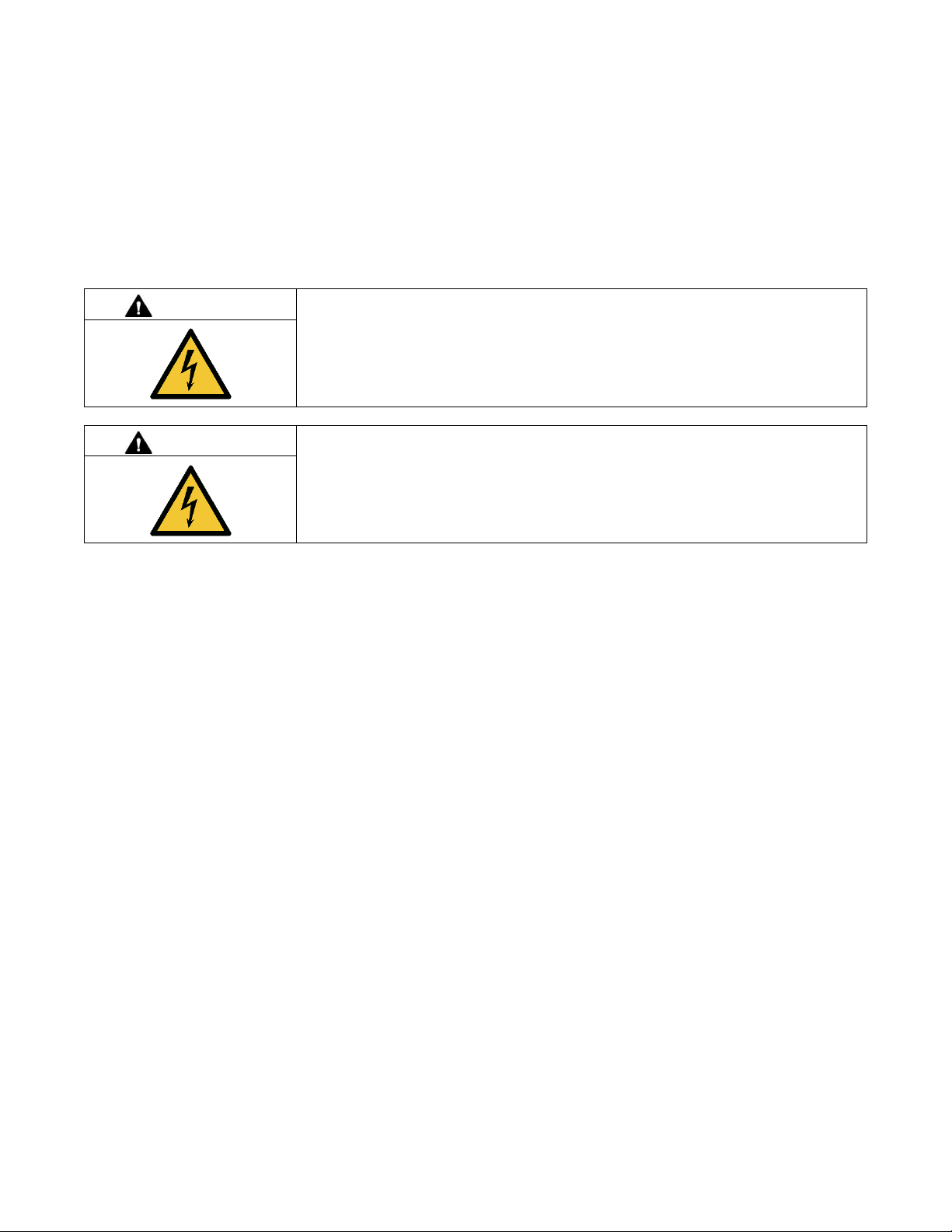
DANGER
Hazardous voltage.
Will cause severe injury or death.
Disconnect all power sources before opening the enclosure.
DANGER
Hazardous voltage.
Will cause severe injury or death.
Only authorized personnel should open the enclosure.
equipment connected to the set, disable the generator set as follows: (1) If the controller is not already in the MAN (manual)
mode, press the Controller Mode button and then press the MAN mode button. (2) If the generator set is running, press and hold
the Manual-Stop button for at least 2 seconds to stop the generator set. (3) Press the Controller Mode button and then press
the controller Off mode button. (4) Disconnect the power to the battery charger, if equipped. (5) Remove the battery cables,
negative (–) lead first. Reconnect the negative (–) lead last when reconnecting the battery. Follow these precautions to prevent
the starting of the generator set by the remote start/stop switch.
(Decision-Maker® 8000 Controller)
Hazardous Voltage/Moving Parts
Grounding electrical equipment. Hazardous voltage will cause severe injury or death. Electrocution is possible whenever
electricity is present. Ensure you comply with all applicable codes and standards. Electrically ground the generator set, transfer
switch, and related equipment and electrical circuits. Turn off the main circuit breakers of all power sources before servicing the
equipment. Never contact electrical leads or appliances when standing in water or on wet ground because these conditions
increase the risk of electrocution.
Short circuits. Hazardous voltage/current will cause severe injury or death. Short circuits can cause bodily injury and/or
equipment damage. Do not contact electrical connections with tools or jewelry while making adjustments or repairs. Remove all
jewelry before servicing the equipment.
Making line or auxiliary connections. Hazardous voltage will cause severe injury or death. To prevent electrical shock
deenergize the normal power source before making any line or auxiliary connections.
Servicing the transfer switch. Hazardous voltage will cause severe injury or death. Deenergize all power sources before
servicing. Turn off the main circuit breakers of all transfer switch power sources and disable all generator sets as follows: (1)
Move all generator set master controller switches to the OFF position. (2) Disconnect power to all battery chargers. (3)
Disconnect all battery cables, negative (–) leads first. Reconnect negative (–) leads last when reconnecting the battery cables
after servicing. Follow these precautions to prevent the starting of generator sets by an automatic transfer switch, remote
start/stop switch, or engine start command from a remote computer. Before servicing any components inside the enclosure: (1)
Remove all jewelry. (2) Stand on a dry, approved electrically insulated mat. (3) Test circuits with a voltmeter to verify that they
are deenergized.
(Decision-Maker® 3+ and 550 Controllers)
Servicing the transfer switch. Hazardous voltage will cause severe injury or death. Deenergize all power sources before
servicing. Turn off the main circuit breakers of all transfer switch power sources and disable all generator sets as follows: (1)
Press the generator set off/reset button to shut down the generator set. (2) Disconnect power to all battery chargers. (3)
Disconnect all battery cables, negative (–) leads first. Reconnect negative (–) leads last when reconnecting the battery cables
after servicing. Follow these precautions to prevent the starting of generator sets by an automatic transfer switch, remote
start/stop switch, or engine start command from a remote computer. Before servicing any components inside the enclosure: (1)
Remove all jewelry. (2) Stand on a dry, approved electrically insulated mat. (3) Test circuits with a voltmeter to verify that they
are deenergized.
(APM402, APM603, RDC, DC, RDC2, DC2, Decision-Maker® 3000, 3500 and 6000 Controllers)
6 TP-7280 1/24
Page 7
TP-7280 1/24 7
Testing live electrical circuits. Hazardous voltage or current will cause severe injury or death. Have trained and qualified
personnel take diagnostic measurements of live circuits. Use adequately rated test equipment with electrically insulated probes
and follow the instructions of the test equipment manufacturer when performing voltage tests. Observe the following precautions
when performing voltage tests: (1) Remove all jewelry. (2) Stand on a dry, approved electrically insulated mat. (3) Do not touch
the enclosure or components inside the enclosure. (4) Be prepared for the system to operate automatically. (600 volts and under)
Heavy Equipment
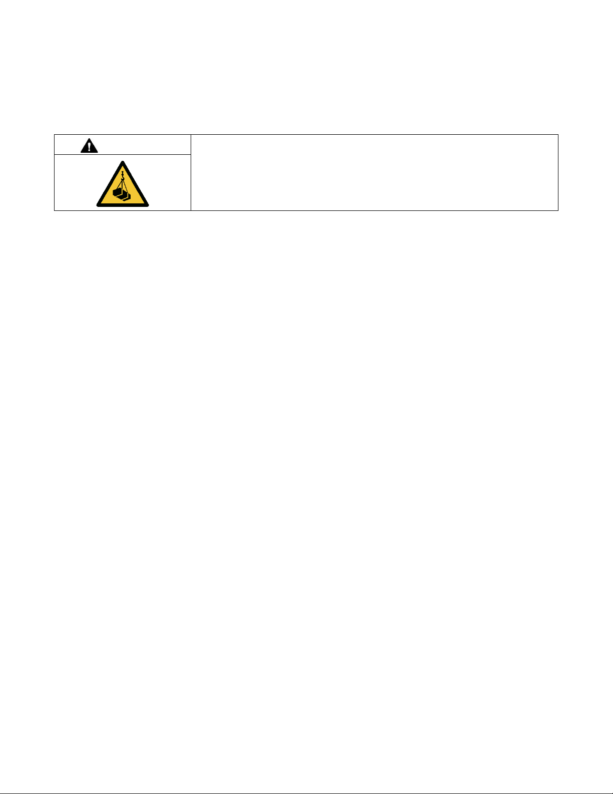
WARNING
Unbalanced weight.
Improper lifting can cause severe injury or death and equipment damage.
Use adequate lifting capacity.
Never leave the transfer switch standing upright unless it is securely bolted in place or
stabilized
Notice
NOTICE
Improper operator handle usage. Use the manual operator handle on the transfer switch for maintenance purposes only.
Return the transfer switch to the normal position. Remove the manual operator handle, if used, and store it in the place provided
on the transfer switch when service is completed.
NOTICE
Foreign material contamination. Cover the transfer switch during installation to keep dirt, grit, metal drill chips, and other debris
out of the components. Cover the solenoid mechanism during installation. After installation, use the manual operating handle to
cycle the contactor to verify that it operates freely. Do not use a screwdriver to force the contactor mechanism.
NOTICE
Electrostatic discharge damage. Electrostatic discharge (ESD) damages electronic circuit boards. Prevent electrostatic
discharge damage by wearing an approved grounding wrist strap when handling electronic circuit boards or integrated circuits.
An approved grounding wrist strap provides a high resistance (about 1 megohm), not a direct short, to ground.
Page 8

8 TP-7280 1/24
Page 9

TP-7280 1/24 9
Introduction
This manual provides operation and installation instructions for the following Kohler® Contactor-based Service Entrance Rated
Automatic Transfer Switches (ATS):
• Model KUS standard-transition service entrance rated ATS.
• Model KUP programmed-transition service entrance rated ATS.
The transfer switch is equipped with the Kohler® Decision-Maker® MPAC 1500 transfer switch controller.
A separate manual provided with the transfer switch covers the transfer switch controller operation. See List of Related Materials
for the document part number.
Information in this publication represents data available at the time of print. Kohler Co. reserves the right to change this literature
and the products represented without notice and without any obligation or liability whatsoever.
Read this manual and carefully follow all procedures and safety precautions to ensure proper equipment operation and to avoid
bodily injury. Read and follow the Safety Precautions and Instructions section at the beginning of this manual. Keep this manual
with the equipment for future reference.
The equipment service requirements are very important to safe and efficient operation. Inspect parts often and perform required
service at the prescribed intervals. See the controller Operation manual for the service schedule. Obtain service from an
authorized service distributor/ dealer to keep equipment in top condition.
List of Related Literature
A separate manual covers the transfer switch controller and related accessories. Separate manuals contain service information
for transfer switch power switching devices and electrical controls. For replacement parts, refer to the Kohler Power Parts online
parts system.
The following table lists the part numbers for related literature.
Literature Item
Part Number
Specification Sheet, Decision-Maker® MPAC 1500 Controller
G11-128
Specification Sheet, Model KUS/KUP ATS
G11-153
Operation Manual, Decision-Maker® MPAC 1500 Controller
TP-6883
Installation Manual, Model KUS/KUP
TP-7280
Wiring Diagram Manual, Model KUS/KUP
TP-7281
Service Manual, Model KUS/KUP
TP-7282
Page 10

10 TP-7280 1/24
Service Assistance
For professional advice and conscientious service, please
contact your nearest Kohler distributor or dealer.
• Visit the Kohler Co. website at KOHLERPower.com.
• Look at the labels and decals on your Kohler product
or review the appropriate literature or documents
included with the product.
• Call toll free in the US and Canada 1-800-544-2444.
• Outside the US and Canada, call the nearest
regional office.
Headquarters Europe, Middle East, Africa (EMEA)
Kohler EMEA Headquarters
Netherlands B.V.
Kristallaan 1
4761 ZC Zevenbergen
The Netherlands
Phone: (31) 168 331630
Fax: (31) 168 331631
Asia Pacific
Kohler Asia Pacific Headquarters
Singapore, Republic of Singapore
Phone: (65) 6264-6422
Fax: (65) 6264-6455
China
North China Regional Office, Beijing
Phone: (86) 10 6518 7950
(86) 10 6518 7951
(86) 10 6518 7952
Fax: (86) 10 6518 7955
East China Regional Office, Shanghai
Phone: (86) 21 6288 0500
Fax: (86) 21 6288 0550
India, Bangladesh, Sri Lanka
India Regional Office
Bangalore, India
Phone: (91) 80 3366208
(91) 80 3366231
Fax: (91) 80 3315972
Japan, Korea
North Asia Regional Office
Tokyo, Japan
Phone: (813) 3440-4515
Fax: (813) 3440-2727
Page 11
TP-7280 1/24 11
Section 1. Product Description
1.1 General Description
An automatic transfer switch (ATS) transfers electrical loads from a Normal (preferred) source of electrical power to an
Emergency (standby) source when the Normal source falls outside the acceptable electrical parameters.
Model KUS/KUP automatic transfer switches employ a contactor-based power switching unit and the Kohler Decision
Maker® 1500 controller to automatically transfer system load to a generator supply in the event of a utility supply failure. When
the Normal (preferred) source fails, the ATS signals the Emergency (standby) source generator set to start. When the Emergency
(standby) source reaches acceptable levels and stabilizes, the ATS transfers the load from the Normal (preferred) source to the
Emergency (standby) source. The ATS continuously monitors the Normal (preferred) source. When the Normal (preferred)
source returns and stabilizes, the ATS transfers the load back to Normal. After transferring the load back to Normal (preferred),
the ATS removes the generator start signal, allowing the generator set to shut down.
Model KUS/KUP service entrance rated transfer switches have integral overcurrent protection with a shunt trip module supplied
for the utility source as standard equipment. This allows installation at the point of service entrance and eliminates the need to
have a separate upstream utility source circuit breaker or disconnect. Refer to the Overcurrent Protection Section for more
information.
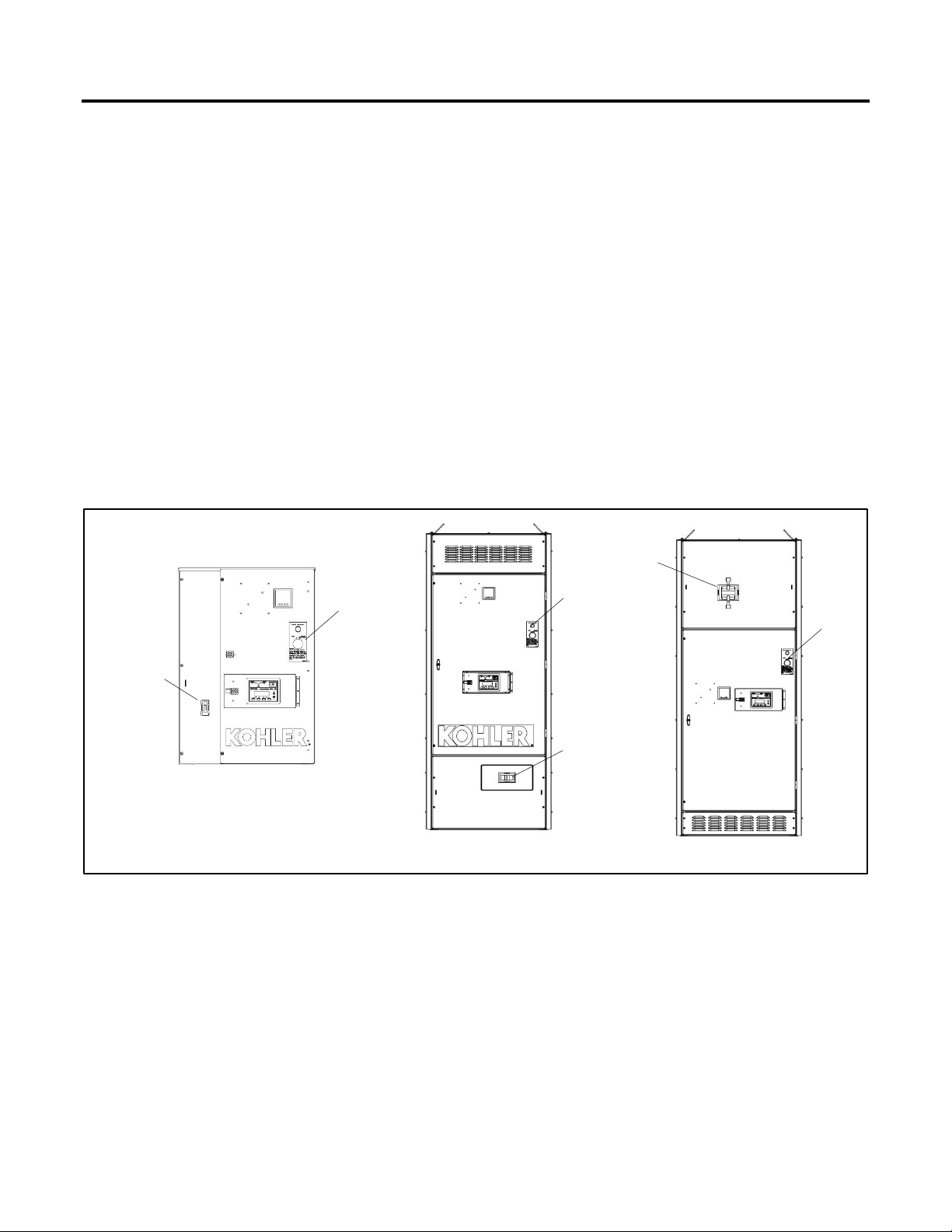
Figure 1 shows examples of some typical service entrance rated ATSs. The utility circuit breaker location varies for different
models.
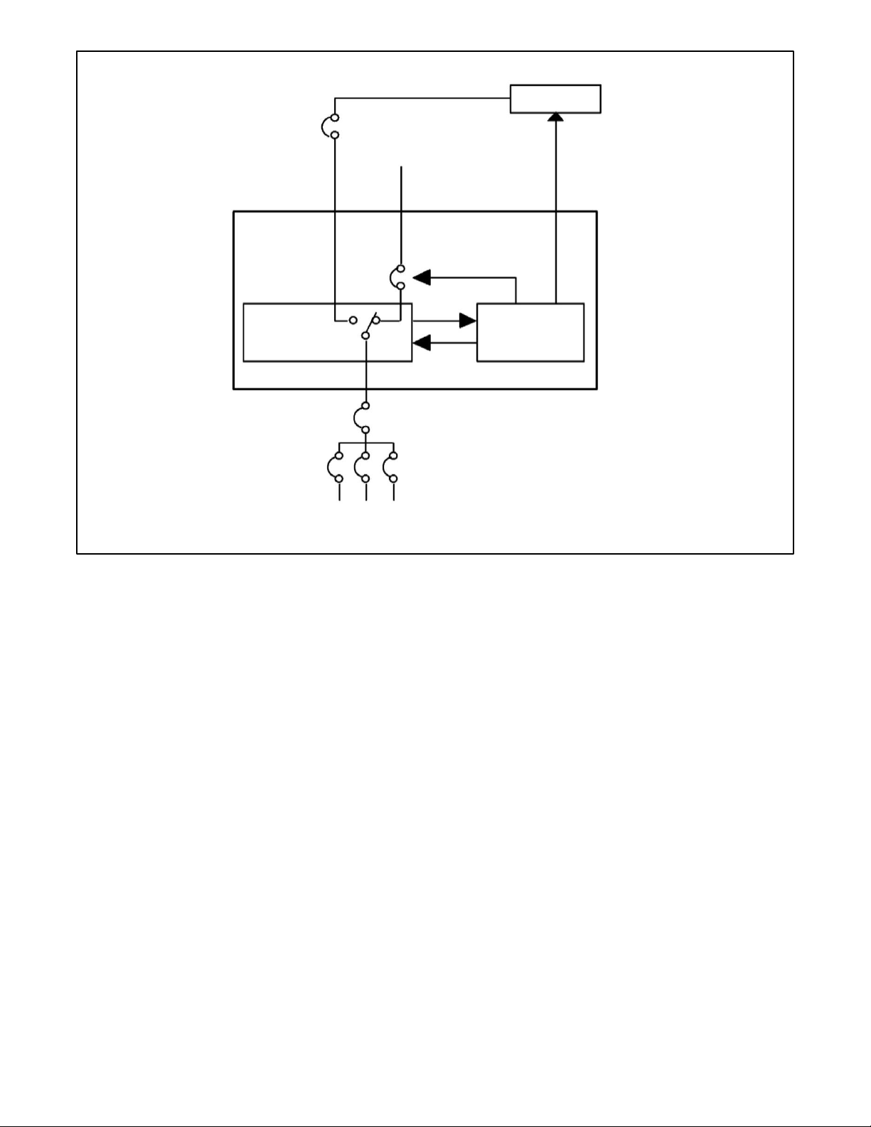
Figure 2 shows a typical installation block diagram.
Figure 1 Typical Service Entrance-Rated Automatic Transfer Switches
70-225 Amps
1600-3000 Amps
800-1200 Amps
2
1. Utility Circuit Breaker
2. Service Disconnect Switch
1
1
1
2
2
Page 12
12 TP-7280 1/24
Figure 2 Service Entrance Rated ATS Block Diagram
1.2 Overcurrent Protection
Model KUS/KUP service entrance rated transfer switches have an integral overcurrent protection with shunt trip supplied on the
utility source as standard. An upstream overcurrent protection device is required for the generator source. The type of overcurrent
protection varies with ATS amperage size and optional features specified. Transfer switches rated 70A through 200A use
nonadjustable thermal-magnetic type trip units (standard) or electronic trip units (optional). Transfer switches rated 250A through
4000A use adjustable electronic type with long time and instantaneous trip unit elements. Ground fault protection is standard on
1000 Amp and larger units. See the Model KUS/KUP Specification Sheet for available circuit breaker sizes and trip types.
For overcurrent trip and circuit breaker reset information, see the Operation Section of this document.
Generator
Emergency
(Generator)
Circuit Breaker
Automatic Transfer Switch
Normal (Utility)
Power
Electrical
Controls
To Load
Power Switching
Device (Contactor)
TP-7280
Page 13
TP-7280 1/24 13
1.3 Nameplate
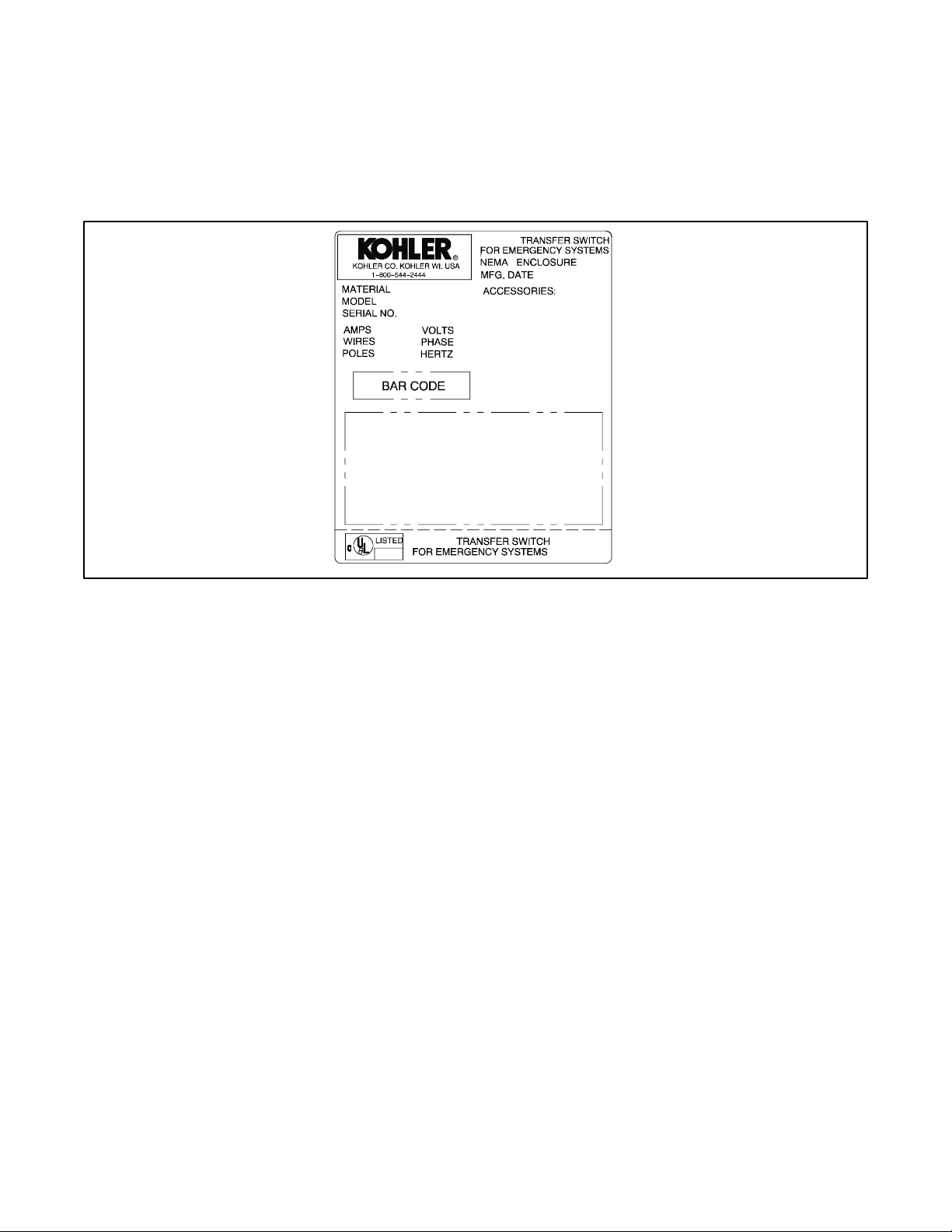
A nameplate attached to the controller cover on the inside of the enclosure door includes a model designation, a serial number,
ratings, and other information about the transfer switch. See Figure 3. The serial number is also shown on a label inside the
transfer switch enclosure.
Copy the model designation, serial number, and accessory information from the nameplate to the spaces provided in the Product
Identification Information section inside the front cover of this manual for use when requesting service or parts.
Figure 3 Typical Transfer Switch Nameplate
GM21291
Page 14
14 TP-7280 1/24
1.4 Model Designation
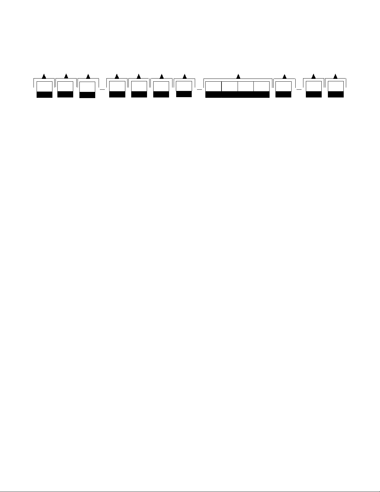
Record the transfer switch model designation in the boxes. The transfer switch model designation defines
characteristics and ratings as explained below.
Sample Model Designation: KUS-DNTA-0400S-XS
Model
Enclosure
K:
Kohler
A: NEMA 1
D: NEMA 4
B: NEMA 12
F: NEMA 4X
Mechanism
C: NEMA 3R
U:
Service Entrance, Utility
Current, Amps
Transition
0070
0250
1600
S:
Standard
0100
0400
2000
P:
Programmed
0150
0600
2600
0200
0800
3000
Controller
0225
1200
4000
D:
Decision-Maker® MPAC 1500, Automatic
Connections
Voltage/Frequency
S: Standard
C:
208 Volts /60 Hz
K:
440 Volts /60 Hz
D:
220 Volts /50 Hz
M:
480 Volts /60 Hz
Utility Disconnect
F:
240 Volts /60 Hz
N:
600 Volts /60 Hz
U: 80% TM
G:
380 Volts /50 Hz
P:
380 Volts/60 Hz
V: 100% TM
H:
400 Volts/50 Hz
R:
220 Volts/60 Hz
W: 80% ET
J:
416 Volts /50 Hz
S:
400 Volts/60 Hz
X: 100% ET
Number of Poles/Wires
Fault Level
N:
2 Poles/3 Wires, Solid Neutral
S: Standard
T:
3 Poles/4 Wires, Solid Neutral
H: High Fault
V:
4 Poles/4 Wires, Switched Neutral
Note:
Some selections are not available for every model. Contact your Kohler distributor for availability.
Model
Mechanism
Transition Poles
Enclosure
Current
Rating
Connections
Utility
Disconnect Fault Level
Page 15

TP-7280 1/24 15
Section 2. Installation
2.1 Introduction
Kohler® transfer switches are shipped factory-wired, factory-tested, and ready for installation. Have the equipment installed only
by trained and qualified personnel and verify that the installation complies with applicable codes and standards. Switch
installation includes the following steps:
• Unpack and inspect the transfer switch upon receipt.
• Verify that the transfer switch voltage and frequency ratings match the voltages and frequencies of the sources.
• Install the transfer switch.
• Check the manual operation.
• Connect the controller harness and ground lead.
• Connect the generator set engine start leads.
• Connect the normal power source (utility), emergency power source (generator set), and load circuits.
• Connect accessories, if provided.
• Check voltages and operation.
Protect the switch against damage before and during installation.
The functional tests in the functional tests and setup section are a necessary part of the installation. Be sure to perform the
functional tests, which include voltage checks and operation tests, before putting the transfer switch into service.
2.2 Receipt of Unit
2.2.1 Inspection
At the time of delivery, inspect the packaging and the transfer switch for signs of shipping damage. Unpack the transfer switch
as soon as possible and inspect the exterior and interior for shipping damage. If damage and/or rough handling is evident,
immediately file a damage claim with the transportation company.
Page 16

16 TP-7280 1/24
2.2.2 Lifting
WARNING
Unbalanced weight.
Improper lifting can cause severe injury or death and equipment damage.
Use adequate lifting capacity.
Never leave the transfer switch standing upright unless it is securely bolted in place or
stabilized
Refer to Figure 4 for the approximate weight of the transfer switch in a Type 1 enclosure. Use a spreader bar to lift the transfer
switch. Attach the bar only to the enclosure’s mounting holes or lifting brackets; do not lift the unit any other way. Close and latch
the enclosure door before moving the unit.
Model
Amps
NEMA Type
Weight kg (lb.)
2-Pole
3-Pole
4-Pole
KUS
70-225
1
66 (145)
67 (148)
69 (151)
3R
90 (199)
92 (202)
93 (205)
4X
137 (302)
138 (305)
140 (308)
225-600
1
223 (492)
227 (500)
232 (511)
3R
237 (522)
240 (530)
245 (541)
4X
245 (540)
249 (549)
254 (560)
800-1200
1
488 (1075)
497 (1095)
519 (1145)
3R
501 (1105)
510 (1125)
533 (1175)
4X
517 (1140)
526 (1160)
549 (1210)
1600-2000
1
—
846 (1865)
875 (1930)
3R
—
982 (2165)
1011 (2230)
2500-3000
1
—
891 (1965)
921 (2030)
3R
—
1027 (2265)
1057 (2330)
4000
1
—
1581 (3485)
1662 (3665)
3R
—
1762 (3885)
1844 (4065)
KUP
150-600
1
230 (507)
234 (515)
188 (526)
3R
243 (537)
247 (545)
188 (556)
4X
245 (540)
249 (549)
188 (560)
800-1200
1
499 (1100)
512 (1130)
238 (1184)
3R
512 (1130)
526 (1160)
238 (1214)
4X
528 (1165)
542 (1195)
485 (1249)
1600-2000
1
—
907 (2000)
556 (2065)
3R
—
1043 (2300)
1073 (2365)
2500-3000
1
—
977 (2155)
1007 (2220)
3R
—
1113 (2455)
1143 (2520)
4000
1
—
1667 (3675)
1748 (3855)
3R
—
1848 (4075)
1930 (4255)
Figure 4 Approximate Weights
Page 17

TP-7280 1/24 17
2.2.3 Storage
Store the transfer switch in its protective packing until final installation. Protect the transfer switch at all times from moisture,
construction grit, and metal chips. Avoid storage in low-temperature and high-humidity areas where moisture could condense
on the unit. See Figure 5 for acceptable storage temperatures.
Environmental Specifications
Operating Temperature
-20°C to 70°C (-4°F to 158°F)
Storage Temperature
-40°C to 85°C (-40°F to 185°F)
Humidity
5% to 95% noncondensing
Figure 5 Environmental Specifications
2.2.4 Unpacking
Allow the equipment to warm to room temperature for at least 24 hours before unpacking to prevent condensation on the
electrical apparatus. Use care when unpacking to avoid damaging transfer switch components. Remove dirt and packing material
that may have accumulated in the transfer switch or any of its components.
Note:
Do not use compressed air to clean the switch. Cleaning with compressed air can cause debris to lodge in the components and
damage the switch.
Check for and remove lag screws that secure the transfer switch to the shipping skid. Lag screws may be found on the outside
or the inside of the enclosure.
Page 18

18 TP-7280 1/24
2.3 Installation NOTICE
Foreign material contamination. Cover the transfer switch during installation to keep dirt, grit, metal drill chips, and other debris
out of the components. Cover the solenoid mechanism during installation. After installation, use the manual operating handle to
cycle the contactor to verify that it operates freely. Do not use a screwdriver to force the contactor mechanism.
NOTICE
The transfer switch may use both American Standard and metric hardware. Use the correct size tools to prevent rounding of the
bolt heads and nuts.
Check the system voltage and frequency. Compare the voltage and frequency shown on the transfer switch nameplate to the
source voltage and frequency. Do not install the transfer switch if the system voltage and frequency are different from the nominal
normal (utility) source voltage and frequency or the nominal emergency source voltage and frequency shown on the generator
set nameplate.
Plan the installation. Use the dimensions given on the enclosure dimension (ADV) drawings. Select a mounting site that
complies with local electrical code restrictions for the enclosure type. Mount the transfer switch as close to the load and power
sources as possible. Allow adequate space to fully open the enclosure and to service the switch. Provide cable bending space
and clearance to live metal parts.
Outdoor installations. Transfer switches with NEMA 3R, 4, or 4X enclosures can be installed outdoors. In locations with very
high ambient temperatures, installation in a shaded area or a location with the enclosure door facing away from direct sunlight
is recommended.
Prepare the foundation. Ensure that the supporting foundation for the enclosure is level and straight. Refer to the applicable
enclosure outline drawing for all mounting details including door opening space.
For bottom cable entry, if used, install conduit stubs in the foundation. Refer to the enclosure dimension drawing for the conduit
stub locations. When pouring a concrete floor, use interlocking conduit spacer caps or a wood or metal template to maintain
proper conduit alignment.
Installation of IBC seismically certified transfer switches. IBC seismic certification must be requested when the transfer
switch is ordered. See the IBC Seismic Certification section and the transfer switch dimension (ADV) drawings for additional
installation requirements for transfer switches with IBC seismic certification.
Install the ATS. Mount 70-through 225-amp (except 225A/600V) transfer switches to a wall or other rigid vertical supporting
structure. Clearance holes through the back of each enclosure are provided for mounting. Level the enclosure and use shims if
needed to make it plumb. Verify that the door hinges are vertical to avoid distortion of the enclosure or door.
Bolt 225A/600V and 250-amp or larger automatic transfer switches directly to floor mounting pads. Use shims if needed to plumb
the enclosure. Verify that the door hinges are vertical to avoid distortion of the enclosure or door.
2.3.1 IBC Seismic Certification
Automatic transfer switches with seismic certification must be installed according to the instructions in this section. Also refer to
ADV-7456, the Certificate of Compliance provided with the ATS, and the installation (ADV) drawings for the transfer switch.
Abbreviations:
ACI: American Concrete Institute
IBC: International Building Code®
SDS: Design spectral response acceleration at short period, as determined in Section 1615.1.3 of the IBC
Rp: Equipment response modification factor
Ip: Equipment importance factor
ap: In-structure equipment amplification factor
Refer to the International Building Code® for more information.
Page 19

TP-7280 1/24 19
General Seismic Installation Notes (for ATS only):
1. Anchors used for seismic installation must be designed in accordance with ACI 355.2-04. Suggested manufacturers
include Simpson, Ramset, and Hilti.
2. Anchors must be installed to a minimum embedment of 8x the anchor diameter.
3. Anchors must be installed in minimum 4000 psi compressive strength normal weight concrete. Concrete aggregate
must comply with ASTM C33. Installation in structural lightweight concrete is not permitted unless otherwise approved
by the structural engineer of record.
4. Anchors must be installed to the required torque specified by the anchor manufacturer to obtain maximum loading.
5. Anchors must be installed to the anchor spacing required to obtain maximum load and edge distance required to obtain
maximum load unless otherwise approved by the structural engineer of record.
6. Anchors used for seismic installation must be designed and rated to resist seismic loading in accordance with
ACI 355.2-04 and documented in a report by a reputable testing agency (for example, the Evaluation Service Report
issued by the International Code Council).
7. Wide washers must be installed at each anchor location between the anchor head and equipment for tension load
distribution. See applicable ADV drawing for specific anchor information and washer dimensions.
8. Equipment installed on a housekeeping pad requires the housekeeping pad thickness to be at least 1.5x the anchor
embedment depth.
9. All housekeeping pads must be seismically designed and dowelled or cast into the building structure as approved by
the structural engineer of record.
10. Rebar reinforcing in the housekeeping pad is required for all installations.
11. Concrete and rebar reinforcing must be designed in accordance with ACI 318-05.
12. Wall-mounted equipment must be installed to a rebar reinforced structural concrete wall that is seismically designed
and approved by the engineer of record to resist the added seismic loads from components being anchored to the wall.
13. Floor-mounted equipment (with or without a housekeeping pad) must be installed to a rebar reinforced structural
concrete floor that is seismically designed and approved by the engineer of record to resist the added seismic loads
from components being anchored to the floor.
14. When installing to a floor or wall, rebar interference must be considered.
15. Equipment attached to any structural floor or wall other than those constructed of structural concrete and designed to
accept the seismic loads from the mounted equipment are beyond the scope of this specification.
16. Installation to light-weight concrete over steel decking is beyond the scope of this specification.
17. Installation to concrete block or cinder block walls is beyond the scope of this specification.
Page 20
20 TP-7280 1/24
2.4 Manual Operation, Model KUS Standard-Transition Switches
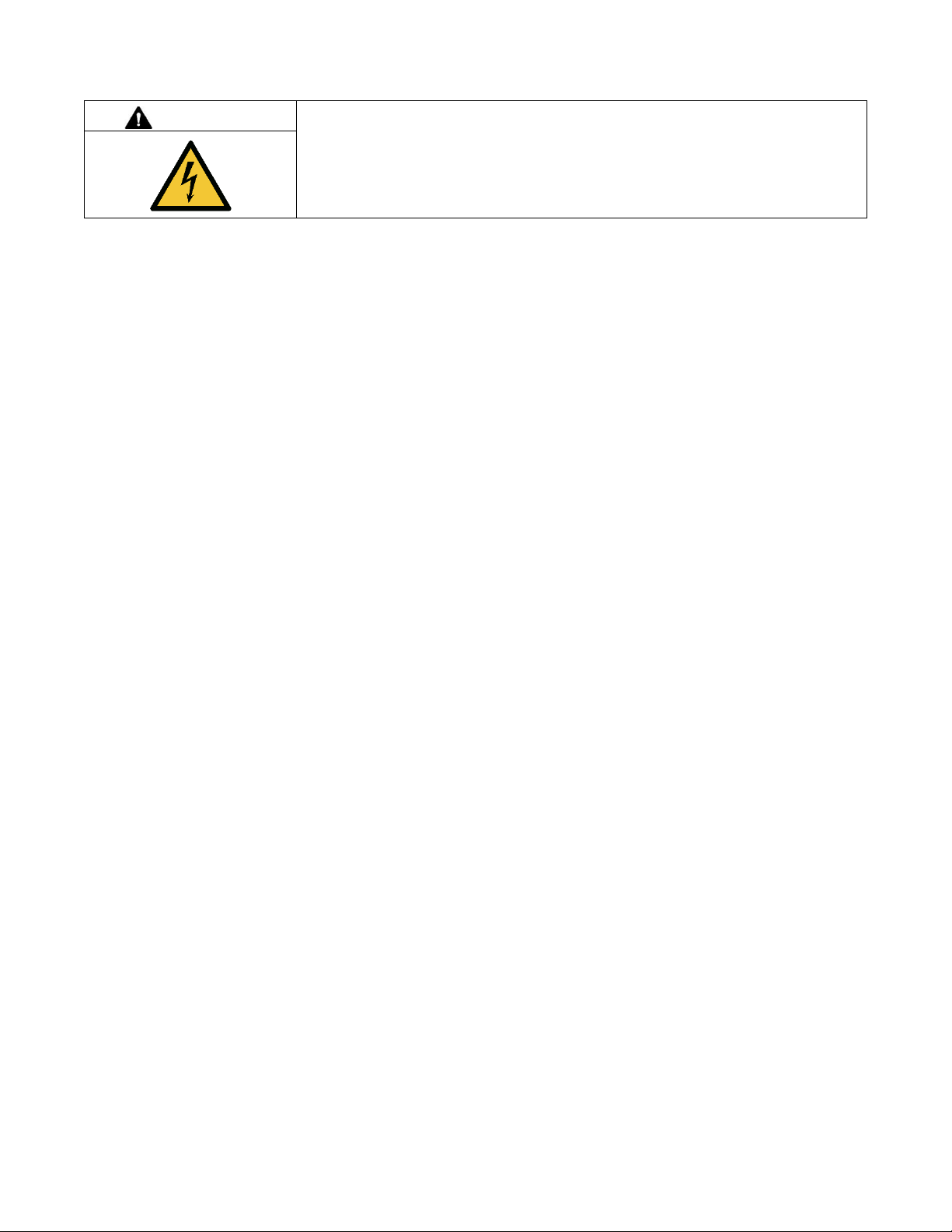
DANGER
Hazardous voltage.
Will cause severe injury or death.
Disconnect all power sources before opening the enclosure.
Servicing the transfer switch. Hazardous voltage will cause severe injury or death. Deenergize all power sources before
servicing. Turn off the main circuit breakers of all transfer switch power sources and disable all generator sets as follows: (1)
Press the generator set off/reset button to shut down the generator set. (2) Disconnect power to all battery chargers. (3)
Disconnect all battery cables, negative (–) leads first. Reconnect negative (–) leads last when reconnecting the battery cables
after servicing. Follow these precautions to prevent the starting of generator sets by an automatic transfer switch, remote
start/stop switch, or engine start command from a remote computer. Before servicing any components inside the enclosure: (1)
Remove all jewelry. (2) Stand on a dry, approved electrically insulated mat. (3) Test circuits with a voltmeter to verify that they
are deenergized.
Note:
A manual operation handle is provided on the transfer switch for maintenance purposes only. Do not use the manual operation
handle to transfer the load with the power connected.
Use the manual operation handle to check the manual operation before energizing the transfer switch. Use the following manual
operation procedures to verify that the contactor operates smoothly without binding.
Note:
A contactor in normal and serviceable condition operates smoothly without binding. Do not place the transfer switch into service
if the contactor does not operate smoothly; contact an authorized distributor/dealer to service the contactor.
2.4.1 Manual Operation, 70-225 Amp Standard-Transition Switches
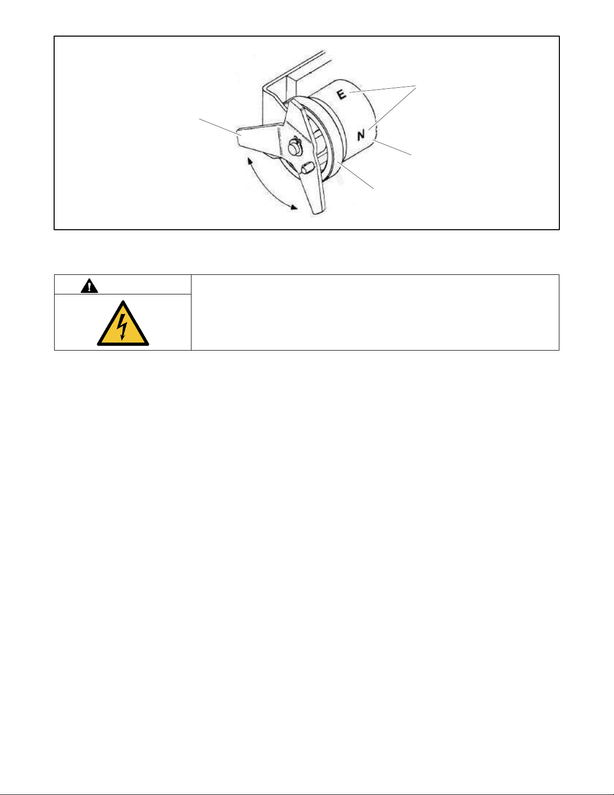
The 70-225 amp standard-transition models have an attached manual operating handle. See Figure 6.
Note:
For 225A/600V models, see the Manual Operation, 225A/600V and 250-4000 Amp Standard-Transition Switches section.
Manual Operation Test Procedure, 70-225 Amp Transfer Switches
1. Disable the generator set to prevent starting, open the line circuit breaker on the generator set, and perform the service
disconnect procedure to disconnect all power sources before manually operating the transfer switch.
2. To manually operate the transfer switch, turn the attached handle by hand. See Figure 6. The maintenance handle
turns in the opposite direction of the weight. It should operate smoothly without any binding. If it does not, check for
shipping damage or construction debris.
3. Return the transfer switch to the Normal position.
Page 21
TP-7280 1/24 21
Figure 6 Manual Operation Handle, 70-225 Amp Model KUS
2.4.2 Manual Operation, 225A/600V and 250-4000 Amp Standard-Transition Switches
DANGER
Hazardous voltage.
Will cause severe injury or death.
Disconnect all power sources before opening the enclosure.
NOTICE
Improper operator handle usage. Use the manual operator handle on the transfer switch for maintenance purposes only.
Return the transfer switch to the normal position. Remove the manual operator handle, if used, and store it in the place provided
on the transfer switch when service is completed.
The 250-4000 amp standard-transition models use a detachable manual operating handle.
Manual Operation Test Procedure, 225A/600V and 250-1200 Amp Standard-Transition Transfer Switches
1. Disable the generator set to prevent starting and disconnect all power sources before manually operating the transfer
switch.
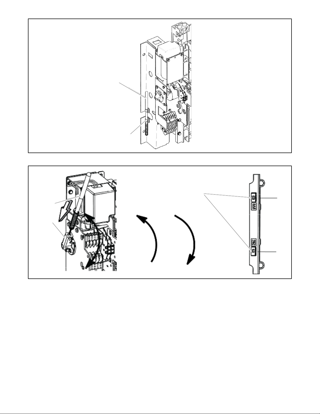
2. Remove the maintenance handle from the clip(s) on the left side of the transfer switch frame. See Figure 7.
3. 225 (600V) and 250--600 amp switches: See Figure 8. Insert the maintenance handle into the hole in the shaft on the
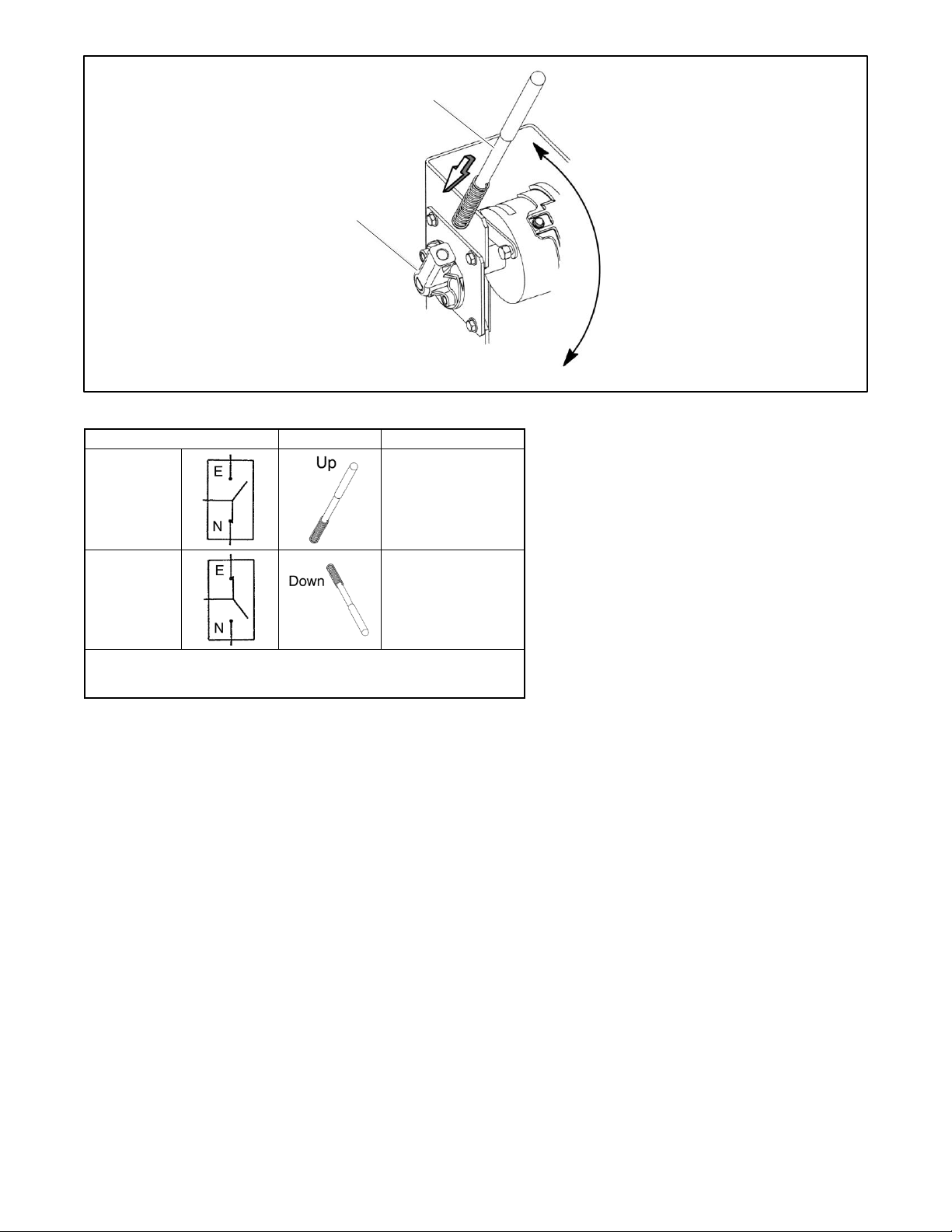
left side of the operator.
800-1200 amp switches: See Figure 9. Insert the maintenance handle into the hole in the molded hub on the left side
of the operator.
4. Move the maintenance handle up or down as shown to manually operate the transfer switch. It should operate smoothly
without any binding. If it does not, check for shipping damage or construction debris. See Figure 10.
5. Return the transfer switch to the Normal position.
6. Remove the maintenance handle and store it on the frame in the clips provided.
Note:
Verify that the maintenance handle has been removed before proceeding.
Handle
Position indicators
Floating weight
Weight
229
Page 22
22 TP-7280 1/24
Figure 7 Detachable Handle Storage (typical)
Figure 8 Manual Operation, 250-600 Amp Model KUS
Storage clip(s)
Maintenance handle
202
Handle
Position indicators (right side of contactor):
O = open, C = closed
283
E
N
N
E
Hub
Page 23
TP-7280 1/24 23
Figure 9 Manual Operation, 800-1200 Amp Model KUS
ATS Position
Handle
Indicators
Normal
E : O
Upper contacts open
N : C
lower contacts closed
Emergency
E : C
Upper contacts closed
N : O
lower contacts open
Note:
If Normal and Emergency connections are reversed, this operation is also
reversed.
Figure 10 Maintenance Handle Positions, 260-1200 Amp Model KUS
Manual Operation Test Procedure, 1600-4000 Amp Standard-Transition Transfer Switches
1. Disable the generator set to prevent starting and disconnect all power sources before manually operating the transfer
switch.
2. Remove the maintenance handle from the clip(s) on the left side of the transfer switch frame. See Figure 7.
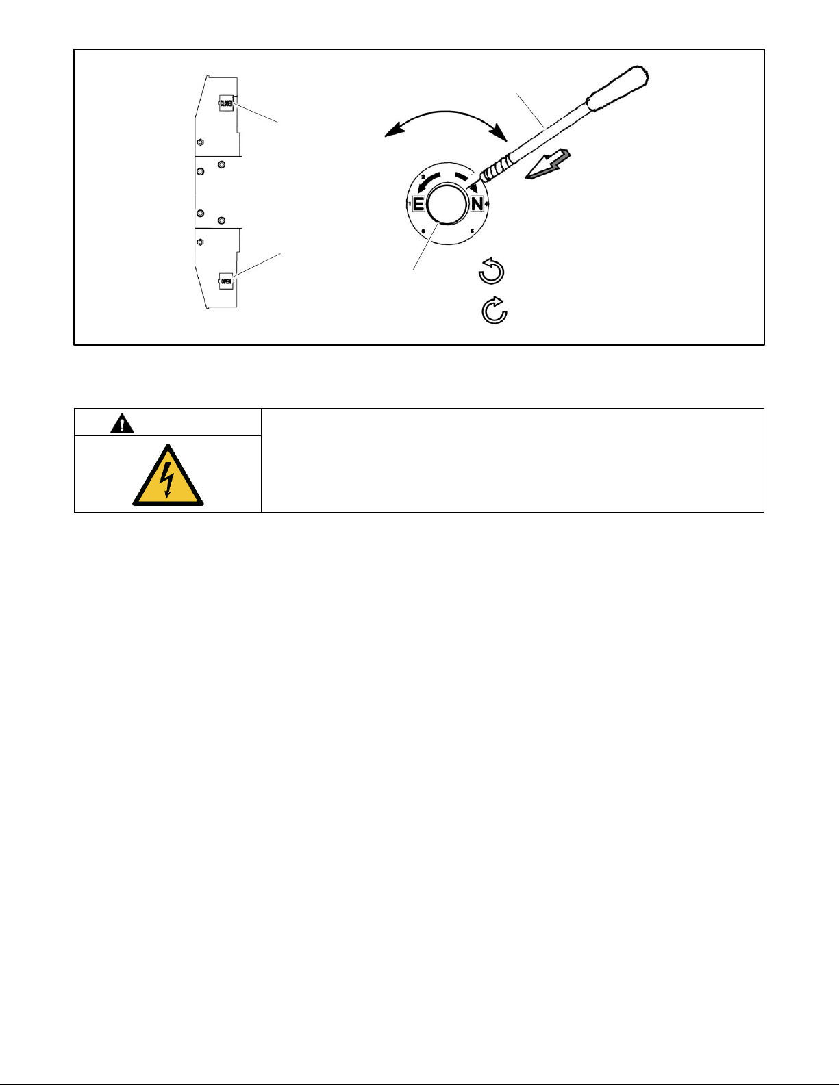
3. See Figure 11. Insert the maintenance handle into the hole in the molded hub.
4. Move the maintenance handle as shown to manually operate the transfer switch. It should operate smoothly without
any binding. If it does not, check for shipping damage or construction debris.
5. Return the transfer switch to the Normal position.
6. Remove the maintenance handle and store it on the transfer switch in the clips provided.
Note:
Verify that the maintenance handle has been removed before proceeding.
Maintenance handle
202
Hub
Page 24
24 TP-7280 1/24
Figure 11 Manual Operation, 1600-4000 Amp Model KUS
2.5 Manual Operation, Model KUP Programmed-Transition Switches
DANGER
Hazardous voltage.
Will cause severe injury or death.
Disconnect all power sources before opening the enclosure.
Servicing the transfer switch. Hazardous voltage will cause severe injury or death. Deenergize all power sources before
servicing. Turn off the main circuit breakers of all transfer switch power sources and disable all generator sets as follows: (1)
Press the generator set off/reset button to shut down the generator set. (2) Disconnect power to all battery chargers. (3)
Disconnect all battery cables, negative (–) leads first. Reconnect negative (–) leads last when reconnecting the battery cables
after servicing. Follow these precautions to prevent the starting of generator sets by an automatic transfer switch, remote
start/stop switch, or engine start command from a remote computer. Before servicing any components inside the enclosure: (1)
Remove all jewelry. (2) Stand on a dry, approved electrically insulated mat. (3) Test circuits with a voltmeter to verify that they
are deenergized.
NOTICE
Improper operator handle usage. Use the manual operator handle on the transfer switch for maintenance purposes only.
Return the transfer switch to the normal position. Remove the manual operator handle, if used, and store it in the place provided
on the transfer switch when service is completed.
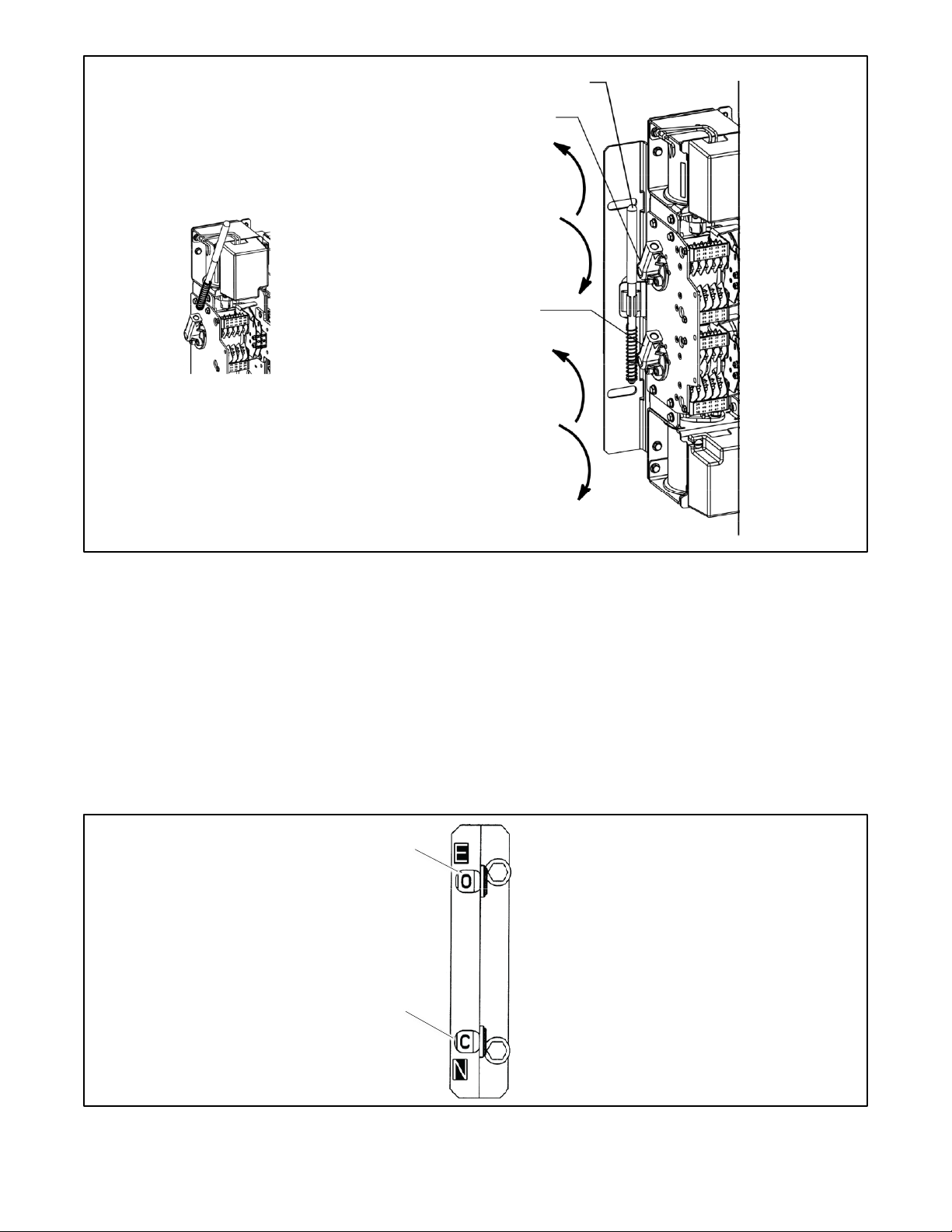
Programmed-transition switches have two operators, Normal and Emergency, on the left side of the contactor assembly.
Mechanical interlocks prevent closing both operators at the same time. Refer to Figure 12 for typical locations of the Normal
and Emergency operators.
Programmed-transition models use a detachable manual operating handle. Position indicators on the right side of the
contactor assembly show the positions of the operators. See the figure titled: Position Indicators.
Insert maintenance handle until
spring is fully compressed
127a
Emergency contact
position indicator
Slide hub onto shaft
Normal contact
position indicator
Position indicators on
LEFT side of contactor
show contacts OPEN or
CLOSED
Turn counterclockwise to Emergency.
Turn clockwise to Normal.
Page 25
TP-7280 1/24 25
Figure 12 Model KCP Manual Operation (typical)
2.5.1 Manual Operation Test Procedure, 150-1200 Amp Programmed-Transition Transfer Switches
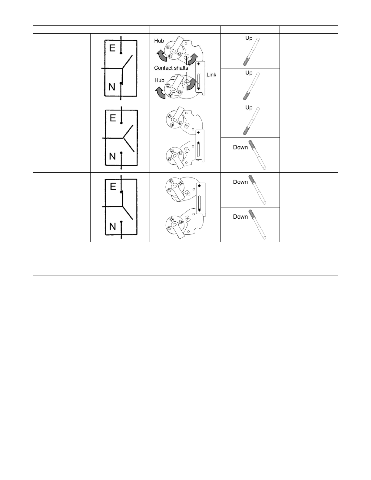
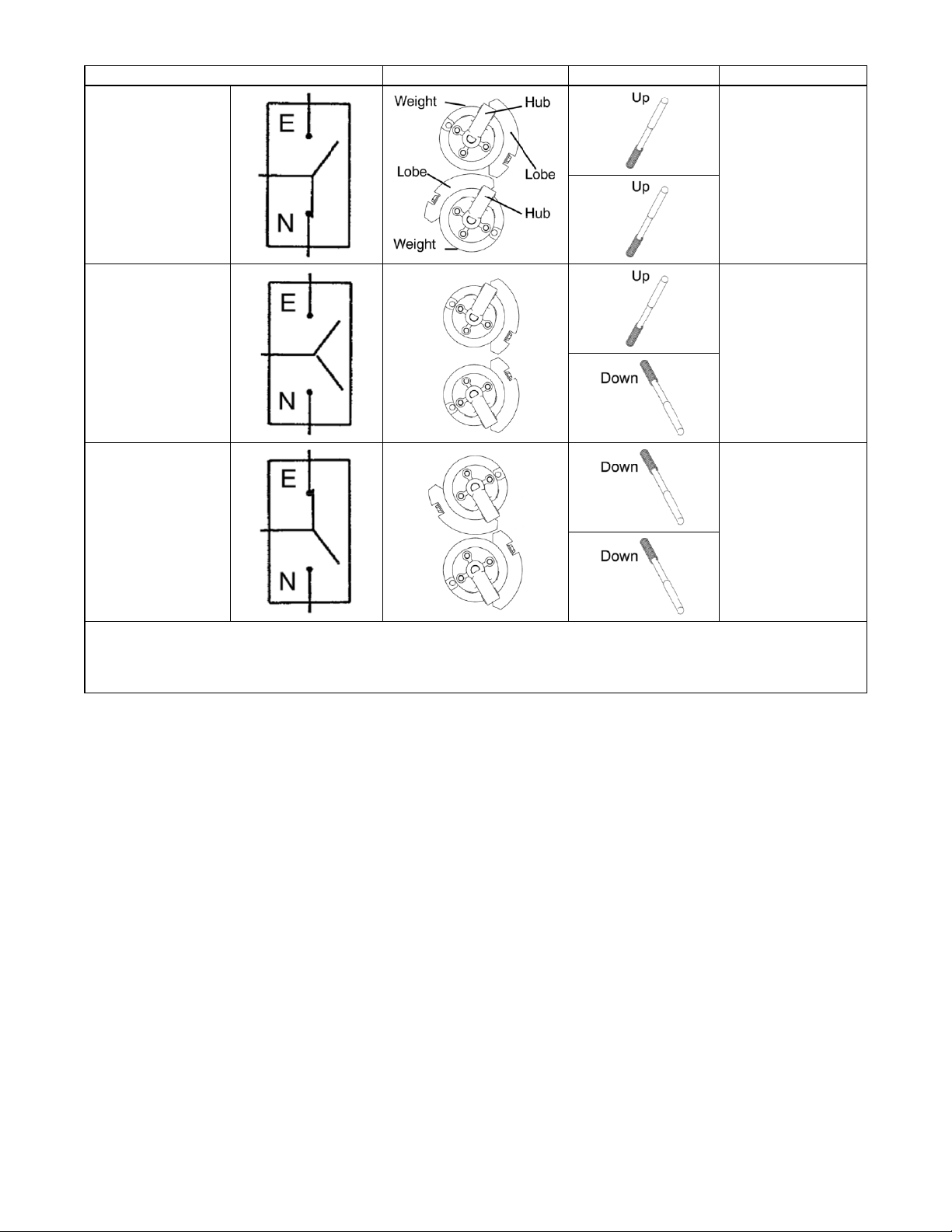
Refer to Figure 13 through Figure 15 during the following procedure.
Check the operation of both operators by following the instructions below for both the Normal and Emergency operators in the
following sequence:
1. Disable the generator set to prevent starting and disconnect all power sources before manually operating the transfer
switch.
2. Starting with the contactor in the Normal position, use the maintenance handle to move the Normal operator from the
closed to the open position.
3. Move the Emergency operator from the open position to the closed position.
4. Return the Emergency operator to the open position and the Normal operator to the closed position.
5. Remove the maintenance handle and store it in the place provided on the switch.
Figure 13 Position Indicators
Handle storage location
Emergency Operator (shown open)
Insert the maintenance handle into the hub.
UPPER SHAFT
UP opens the
Emergency source
contacts
DOWN closes the
Emergency source
contacts
Normal Operator (shown open)
LOWER SHAFT
UP closes the
Normal source
contacts
DOWN opens the
Normal source
contacts
Emergency contact indicator
Normal contact indicator
O = Open; C = Closed
Page 26
26 TP-7280 1/24
Transfer Switch Position
Interlocked Shafts
Maintenance Handle
Shaft Indicators
Normal
E : O
upper contacts open
N : C
lower contacts closed
Load Disconnected
E : O
upper contacts open
N : O
lower contacts open
Emergency
E : C
upper contacts closed
N : O
lower contacts open
Note:
The link between contact shafts prevents closing both N and E contacts.
The hub and contact shaft turn in opposite directions through a cam follower mechanism.
Note:
If Normal and Emergency connections are reversed, this operation is also reversed.
Figure 14 Maintenance Handle Positions, 150-600 Amp Model KUP Only. ALL POWER MUST BE OFF !
Page 27
TP-7280 1/24 27
Transfer Switch Position
Interlocked Shafts
Maintenance Handle
Shaft Indicators
Normal
E : O
upper contacts open
N : C
lower contacts closed
Load Disconnected
E : O
upper contacts open
N : O
lower contacts open
Emergency
E : C
upper contacts closed
N : O
lower contacts open
Note:
If Normal and Emergency connections are reversed this operation is also reversed.
Note:
The lobes prevent closing both N and E contacts at the same time.
Figure 15 Maintenance Handle Positions, 800-1200 Amp Model KUP Only. ALL POWER MUST BE OFF !
Page 28
28 TP-7280 1/24
2.5.2 Manual Operation Test Procedure, 1600-4000 Amp Programmed-Transition Transfer Switches
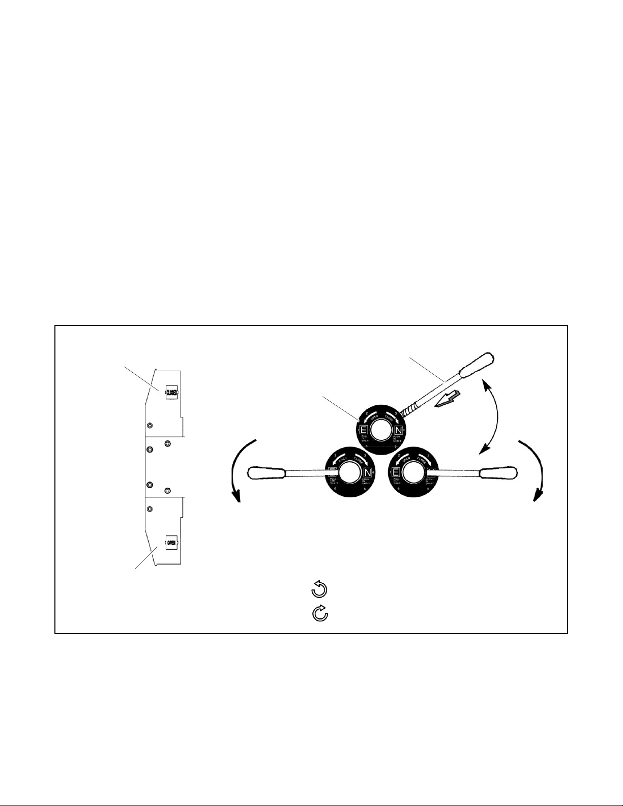
Check the operation of both operators by following the instructions below for both the Normal and Emergency operators. Refer
to Figure 16 during this procedure.
1. Disable the generator set to prevent starting and disconnect all power sources before manually operating the transfer
switch.
2. Install the hub onto the shaft and insert the pin.
3. Insert the manual operating handle into the side hole on the hub until the spring is fully compressed.
4. Push in or pull out the hub to engage the opposite source contacts:
a. Pull out the shaft to engage the emergency source contacts.
b. Push in the shaft to engage the normal source contacts.
5. Grasp the handle firmly with both hands and rotate down:
a. Rotate counterclockwise to open the contacts.
b. Rotate clockwise to close the contacts.
6. Repeat steps 4 and 5 on the other transfer switch.
7. Return the CN transfer switch to the C (closed) position. Return the CE transfer switch to the O (open) position. Remove
the manual operator handle and store it on the transfer switch in the place provided.
Figure 16 Manual Operation, 1600-4000 Amp Model KUP
Hub. Slide onto the shaft and
insert the pin.
Manual operating handle. Insert until
spring is fully compressed.
129
Emergency contacts position
indicator
Normal contacts position
indicator
Pull out shaft for emergency contacts; push in for normal
contacts.
Rotate handle down, clockwise to close or counterclockwise to
open contacts.
Turn counterclockwise to OPEN contacts.
Turn clockwise to CLOSE contacts.
Contact position
indicators (left side)
OPEN
or
CLOSED
Page 29
TP-7280 1/24 29
2.6 Controller Connections
DANGER
Hazardous voltage.
Will cause severe injury or death.
Disconnect all power sources before opening the enclosure.
NOTICE
Electrostatic discharge damage. Electrostatic discharge (ESD) damages electronic circuit boards. Prevent electrostatic
discharge damage by wearing an approved grounding wrist strap when handling electronic circuit boards or integrated circuits.
An approved grounding wrist strap provides a high resistance (about 1 megohm), not a direct short, to ground.
The controller is mounted in a plastic housing on the inside of the transfer switch enclosure door.
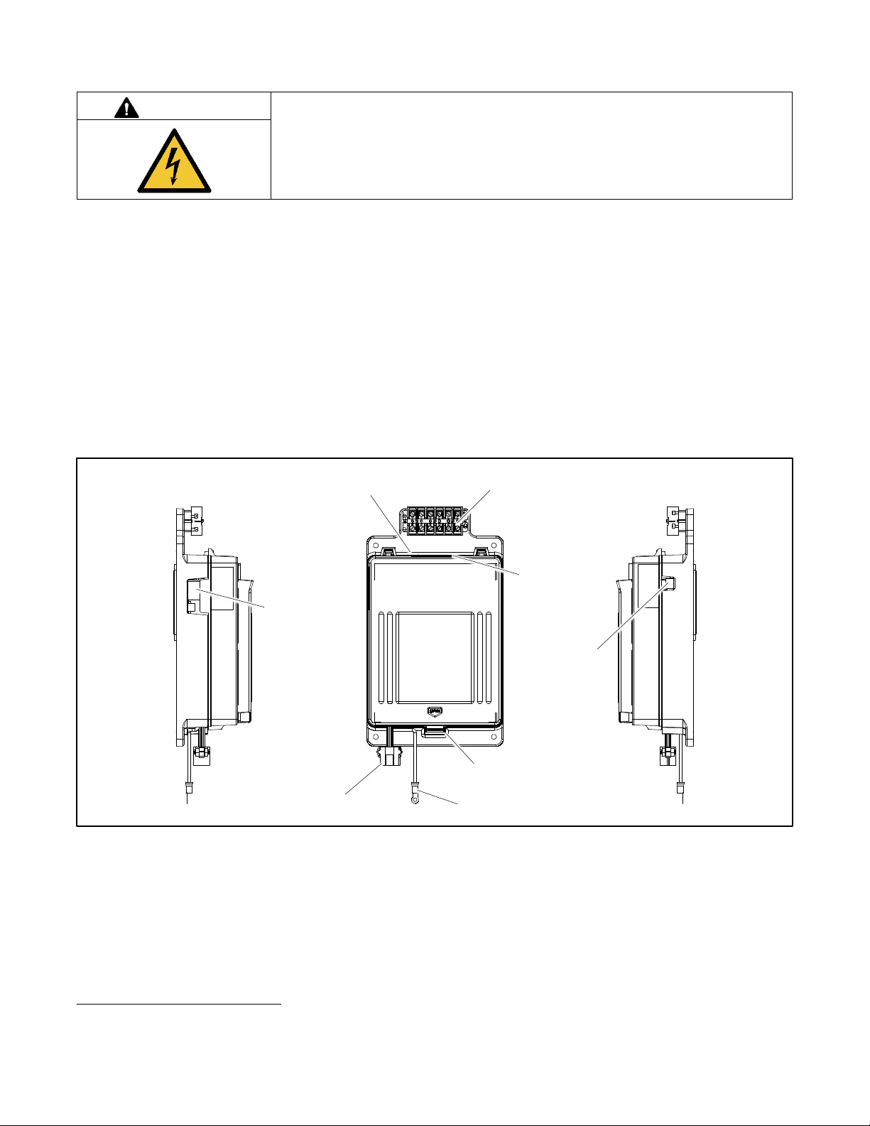
Figure 17 shows the locations of the connectors on the controller. It is not necessary to open the cover to access the Ethernet,
Modbus®, and input/output connectors.
Opening the cover. If necessary, open the plastic housing by pushing up on the latch on the bottom of the cover and swinging
the cover up and out. The cover is hinged at the top. Lift the cover off the hinges to remove it completely, if necessary.
Note:
Always replace the cover before energizing the transfer switch controls.
Figure 17 Controller
Modbus is a registered trademark of Schneider Electric.
Connection for optional current sensing kit
Access
openings to
optional RJ-45
connector
GM85884
Optional I/O
module
connection P16
RS-485 connection TB2
Standard
input/output
connection
Latch
Ground wire
Contactor harness connection
Page 30
30 TP-7280 1/24
2.6.1 Controller Input and Output Connections
The controller provides connections for two programmable inputs and two programmable outputs. On service entrance KUS and
KUP models, one input and two outputs are factory connected and must not be changed.
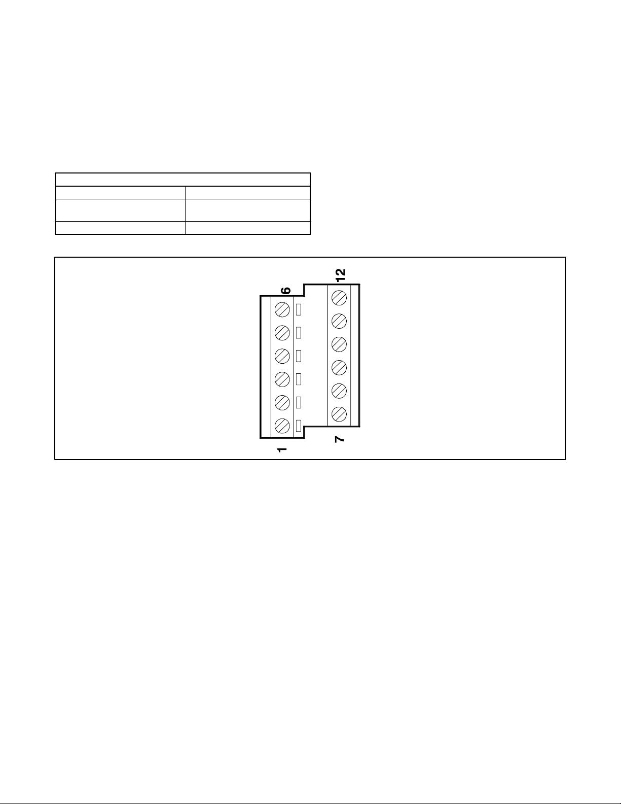
Each input has a signal and a return connection. The outputs are C form contacts with ratings of 500 mA @ 120 VAC. See
Figure 19 for connections. Use #12-24 AWG wire and tighten the connections to 0.5 Nm (4.4 in. lbs.).
See the controller illustration in a previous section for the connector locations and Figure 18 for the I/O connection specifications.
For additional input and output connections, optional input/output modules are available. See the Accessory Modules section
for instructions.
Main Board I/O Specifications
Output contact type
Isolated form C (SPDT)
Output contact rating
1 amp@30 VDC,
500 mA @120 VAC
I/O terminals wire size
#12-24 AWG
Figure 18 Main Board I/O Specifications
Figure 19 Input and Output Connections
2.6.2 Harness Connection
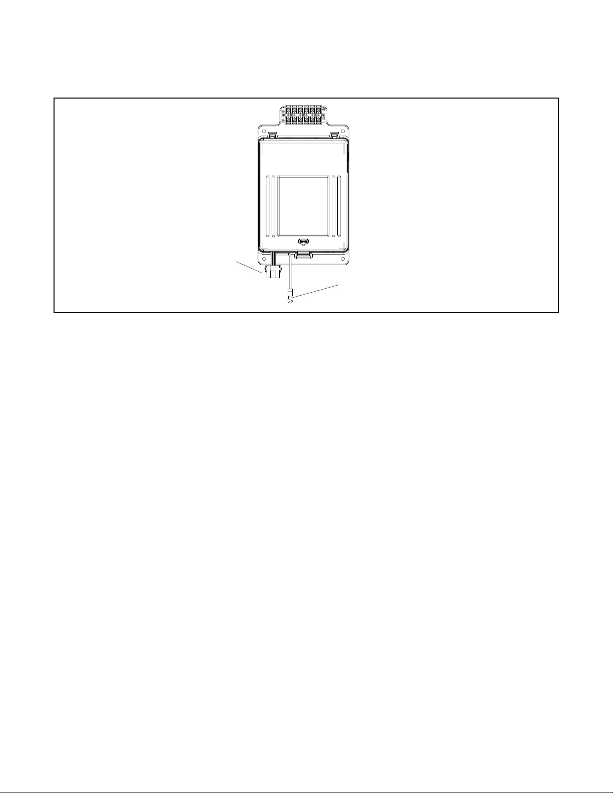
Verify that the contactor harness is connected at the controller base (or at the controller disconnect switch, if equipped). See the
figure titled: Contactor Harness and Controller Ground Connections.
Note:
Verify that the power is disconnected before connecting or disconnecting the contactor harness.
Output 2 C
Output 2 NO
NC = normally closed
NO = normally open
C = common
TB1
6866
Output 2 NC
Output 1 NO
Output 1 C
Output 1 NC
Input 2B
Input 2A
Input 1B
Input 1A
Page 31
TP-7280 1/24 31
2.6.3 Controller Ground
Verify that the grounding wire is connected from the controller’s lower left mounting stud to the enclosure. This connection
provides proper grounding that does not rely upon the door hinges.
Figure 20 Contactor Harness and Controller Ground Connections
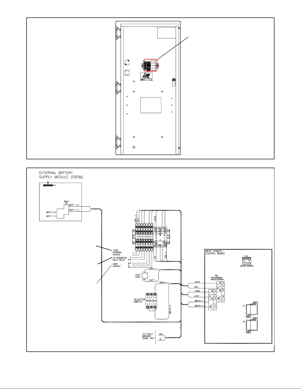
2.7 Service Disconnect Circuit Connections
The External Battery Supply Module is factory-supplied on every unit to maintain power to the controller, provide the proper
status indication (Not in Auto, Service Disconnect), and power the Source Disconnect light. The service disconnect circuit is
connected to the factory-installed External Battery Supply Module.
The service disconnect circuit terminal block is mounted on the inside of the enclosure door. See Figure 21.
• Connect one 12 VDC battery to the service disconnect circuit terminals 1 and 2; see Figure 22Figure 21. The battery
may be the generator set engine starting battery or another battery provided for this purpose. The battery must be
connected to a battery charger to ensure that DC power is always available.
• Connect terminals 3 and 4 to the generator set controller’s fault relay.
• Terminals 5 through 7 provide additional form C contacts to indicate the state of the service disconnect relay. These
connections are for customer-supplied equipment and are optional.
When the operator moves the service disconnect switch to the Service Disconnect position, the ATS controller energizes the
shunt trip coil, which trips (opens) the utility circuit breaker. The shunt trip relay is also connected to an input on the ATS
controller. When the switch is in the Service Disconnect position, the relay closes to signal a fault which prevents the generator
set from starting. The ATS remains in the Normal position.
Turning the service disconnect switch back to AUTO will allow the generator set to be reset (at the generator set controller) and
the engine to start. The ATS will transfer the load to Emergency. Then the Utility breaker can be reset. Normal time delays and
retransfer to normal would occur. The Utility breaker cannot be reset if the service disconnect switch is not in the AUTO position.
Contactor Harness Connection
Ground Connection
GM85844
Page 32
32 TP-7280 1/24
Figure 21 Service Disconnect Circuit Connection Location, Typical (on the inside of the ATS enclosure door)
Figure 22 Service Disconnect Circuit Connections
GM117957
Service disconnect circuit
terminal block location, typical
Inside of enclosure door shown
GM120212
Connect to generator
fault relay
Optional connection
Connect 12 VDC battery
Page 33
TP-7280 1/24 33
2.8 External Battery Supply Module (EBSM)
The external battery supply module connects to the generator set engine start battery or other battery to provide 12 VDC power
to the ATS controller when neither the Normal nor the Emergency source is available. An external battery supply module (EBSM)
is standard, factory-installed equipment for the KUS/KUP service entrance transfer switches. The EBSM is factory-connected to
the service entrance circuit breaker shunt trip circuit.
The installer must connect a 12 VDC battery (typically the generator set engine starting battery) to the shunt trip circuit
as described in the Shunt Trip Circuit Section of this document.
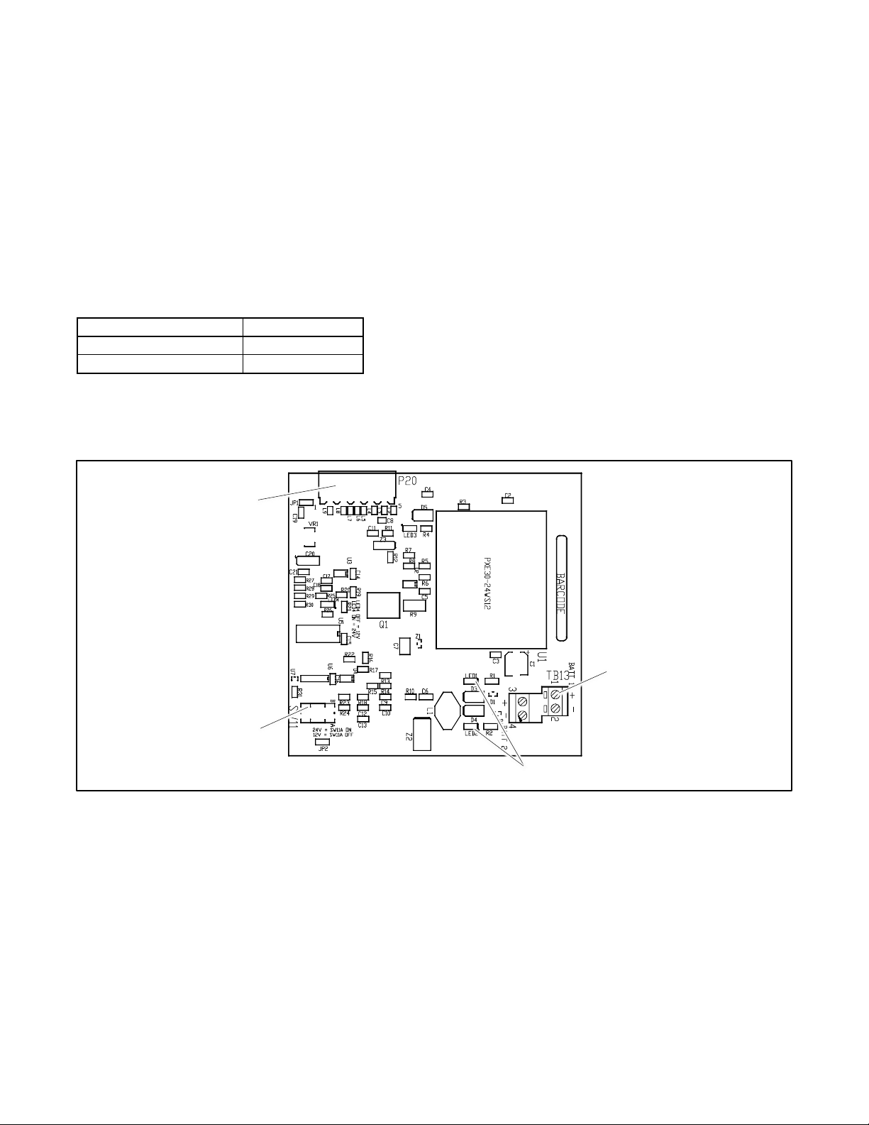
The EBSM produces 2 amps at 12 VDC with 9-36 VDC input. The EBSM input is reverse-polarity protected. If the battery
connections are reversed, red LED1 or LED2 will light. See Figure 21 for the location of the LED indicators.
The EBSM outputs a low battery voltage signal when the external battery voltage falls below 11 VDC for a 12-volt system.
The battery voltage selection DIP switch SW11-1 allows selection between 12-volt and 24-volt systems for low battery voltage
sensing and indication. See Figure 23 and Figure 21. Confirm that voltage selector switch SW11-1 is set to OFF (12 VDC).
DIP Switch SW11-1 Setting
Battery Voltage
OFF
12 VDC
ON
24 VDC
Figure 23 Battery Voltage Selection
Note:
The EBSM has no address switches but must be the last accessory module board on the bus. See the Accessory Module
Mounting section for more information, if needed.
Figure 24 External Battery Supply Module
LED indicators
Battery input connection terminal
block TB13
12/24 volt DIP switch SW11-1.
OFF=12 VDC, ON = 24 VDC
Connector P20
GM42227-A
Page 34
34 TP-7280 1/24
2.9 Electrical Wiring
All internal electrical connections are factory-wired and tested. Field installation includes connecting the sources, loads,
generator start circuit(s), and auxiliary circuits, if used.
Note:
A protective device such as a molded-case circuit breaker or fused disconnect switch MUST be installed on both sources of
incoming power for circuit protection and used as a disconnect device.
Refer to the wiring diagrams provided with the transfer switch. Observe all applicable national, state, and local electrical codes
during installation.
Install DC, control, and communication system wiring in separate conduit from AC power wiring.
It is not necessary to remove pole covers from the transfer switch for cabling. If you do remove them, reinstall them carefully.
WARNING
Accidental starting.
Can cause severe injury or death.
Disconnect the battery cables before working on the generator set. Remove the
negative (–) lead first when disconnecting the battery. Reconnect the negative (–)
lead last when reconnecting the battery.
Servicing the transfer switch. Hazardous voltage will cause severe injury or death. Deenergize all power sources before
servicing. Turn off the main circuit breakers of all transfer switch power sources and disable all generator sets as follows: (1)
Press the generator set off/reset button to shut down the generator set. (2) Disconnect power to all battery chargers. (3)
Disconnect all battery cables, negative (–) leads first. Reconnect negative (–) leads last when reconnecting the battery cables
after servicing. Follow these precautions to prevent the starting of generator sets by an automatic transfer switch, remote
start/stop switch, or engine start command from a remote computer. Before servicing any components inside the enclosure: (1)
Remove all jewelry. (2) Stand on a dry, approved electrically insulated mat. (3) Test circuits with a voltmeter to verify that they
are deenergized.
DANGER
Hazardous voltage.
Will cause severe injury or death.
Disconnect all power sources before opening the enclosure.
Making line or auxiliary connections. Hazardous voltage will cause severe injury or death. To prevent electrical shock
deenergize the normal power source before making any line or auxiliary connections.
Grounding electrical equipment. Hazardous voltage will cause severe injury or death. Electrocution is possible whenever
electricity is present. Ensure you comply with all applicable codes and standards. Electrically ground the generator set, transfer
switch, and related equipment and electrical circuits. Turn off the main circuit breakers of all power sources before servicing the
equipment. Never contact electrical leads or appliances when standing in water or on wet ground because these conditions
increase the risk of electrocution.
NOTICE
Foreign material contamination. Cover the transfer switch during installation to keep dirt, grit, metal drill chips, and other debris
out of the components. Cover the solenoid mechanism during installation. After installation, use the manual operating handle to
cycle the contactor to verify that it operates freely. Do not use a screwdriver to force the contactor mechanism.
Page 35
TP-7280 1/24 35
2.9.1 Source and Load Connections
Note:
Refer to the transfer switch dimension drawing to identify the connection points for the Normal and Emergency source
and load connections.
Determine the cable size. Refer to the transfer switch dimension drawing to determine the cable size and number of cables
required for the transfer switch. Make sure that the cables are suitable for use with the transfer switch lugs. Watertight conduit
hubs may be required for outdoor use.
Drill the entry holes. Cover the transfer switch to protect it from metal chips and construction grit. Then drill entry holes for the
conductors at the locations shown on the enclosure drawings. Remove debris from the enclosure with a vacuum cleaner.
Note:
Do not use compressed air to clean the switch. Cleaning with compressed air can cause debris to lodge in the components and
damage the switch.
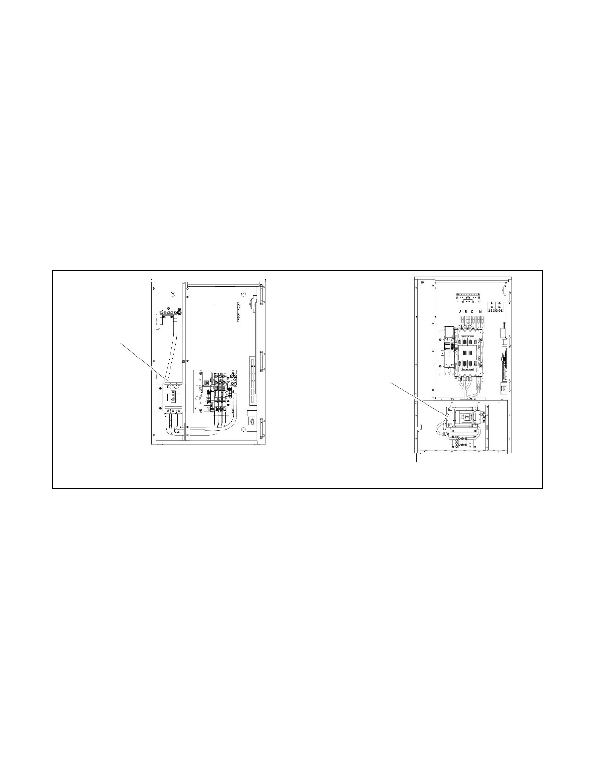
Install and test the power cables. Refer to the transfer switch dimension drawing for connecting lug locations. Connect the
utility source cables to the service entrance circuit breaker, which is located in a separate compartment from the power switching
device. The utility circuit breaker is factory-connected to the Normal source side of the contactor. Connect the emergency source
and load cables to the power switching device.
Figure 25 Typical Utility Power Connections to the Service Entrance Circuit Breaker (see the ADV drawing for your model)
Leave sufficient slack in the power leads to reach all of the power connecting lugs on the utility source side circuit breaker and
the power switching device. Test the power conductors before connecting them to the transfer switch. Installing power cables in
conduit, cable troughs and ceiling-suspended hangers often requires considerable force. Pulling cables can damage insulation
and stretch or break the conductor’s strands.
Test the cables after pulling them into position and before they are connected to verify that they are not defective and that they
were not damaged during installation.
150-600 Amp Models
70-225 Amp Models
ADV-9984
Normal Power
Connection
Normal Power
Connection
ADV-9983
Page 36
36 TP-7280 1/24
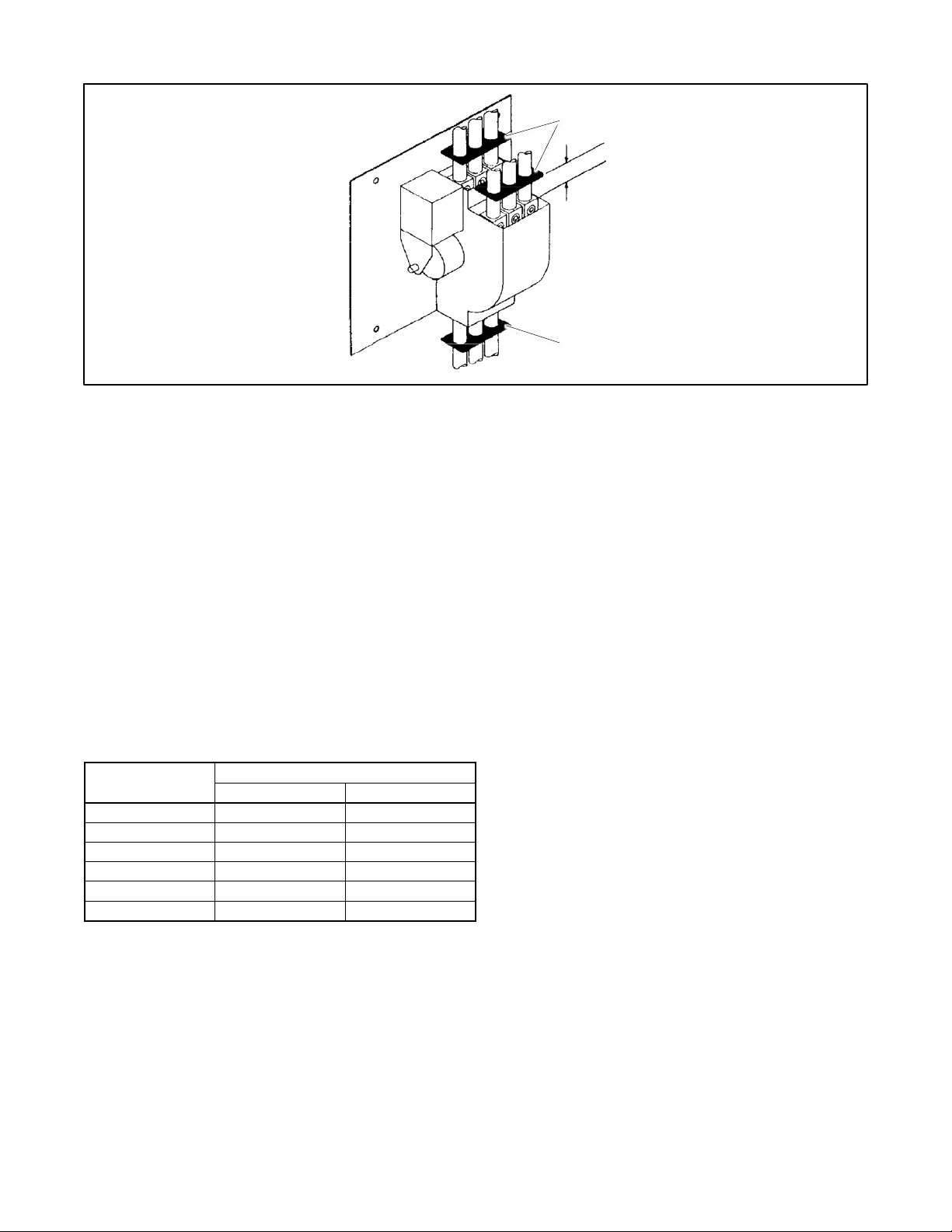
Install the cable spacers provided with 70-225 amp KUS transfer switches as shown in Figure 26.
Figure 26 Cable Spacers for 70-225 KUS Amp Switches
Connect the cables. Be careful when stripping insulation from the cables; avoid nicking or ringing the conductor. Clean cables
with a wire brush to remove surface oxides before connecting them to the terminals. Apply joint compound to the connections
of any aluminum conductors.
Refer to the wiring diagram provided with the switch.
The connection points on the contactor are labeled Normal, Emergency, and Load. Be sure to follow the phase markings (A, B,
C, and N). For single-phase systems, connect to A and C.
Note:
Connect the source and load phases as indicated by the markings and drawings to prevent short circuits and to prevent phase
sensitive load devices from malfunctioning or operating in reverse.
Tighten the lugs. Verify that all connections are consistent with drawings before tightening the lugs. Tighten the utility source
cables to the torque values shown on the circuit breaker. Tighten all emergency source and load cable lug connections to the
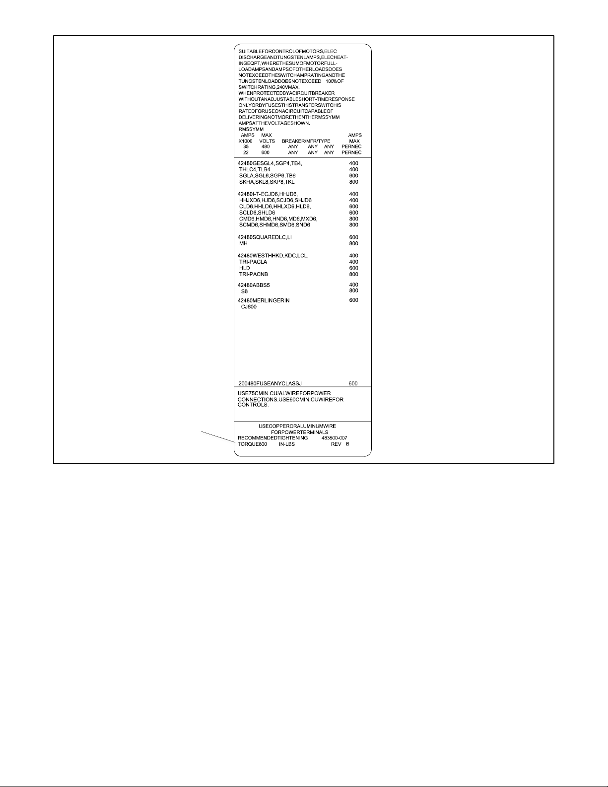
torque values shown on the label on the transfer switch. (See Figure 28 for a typical rating/torque label.) Carefully wipe off any
excess joint compound after tightening the terminal lugs.
For load connections to bus bars, use a compression washer, flat washer, and a minimum grade 5 bolt and torque the
connections to the values in Figure 27.
Bolt Size, inches
Bolt Torque
ft. lb.
Nm
1/4 7 9.5
5/16
12
16.3
3/8
20
27.1
1/2
50
67.8
5/8
95
128.8
3/4
155
210.2
Figure 27 Tightening Torque for Bus Bars
Cable spacers
Cable spacers
127
1 ½ inch approximate
Page 37
TP-7280 1/24 37
Figure 28 Typical Rating/Torque Label
Torque specification
007
Page 38
38 TP-7280 1/24
2.9.2 Engine Start Connection
WARNING
Accidental starting.
Can cause severe injury or death.
Disconnect the battery cables before working on the generator set. Remove the
negative (–) lead first when disconnecting the battery. Reconnect the negative (–)
lead last when reconnecting the battery.
Disabling the generator set. Accidental starting can cause severe injury or death. Before working on the generator set or
equipment connected to the set, disable the generator set as follows: (1) Press the generator set off/reset button to shut down
the generator set. (2) Disconnect the power to the battery charger, if equipped. (3) Remove the battery cables, negative (–) lead
first. Reconnect the negative (–) lead last when reconnecting the battery. Follow these precautions to prevent the starting of the
generator set by the remote start/stop switch.
Prevent the generator set from starting by pressing the OFF button on the generator controller; disconnecting power to the
generator engine start battery charger, if installed; and disconnecting all generator engine start battery cables, negative (-) leads
first.
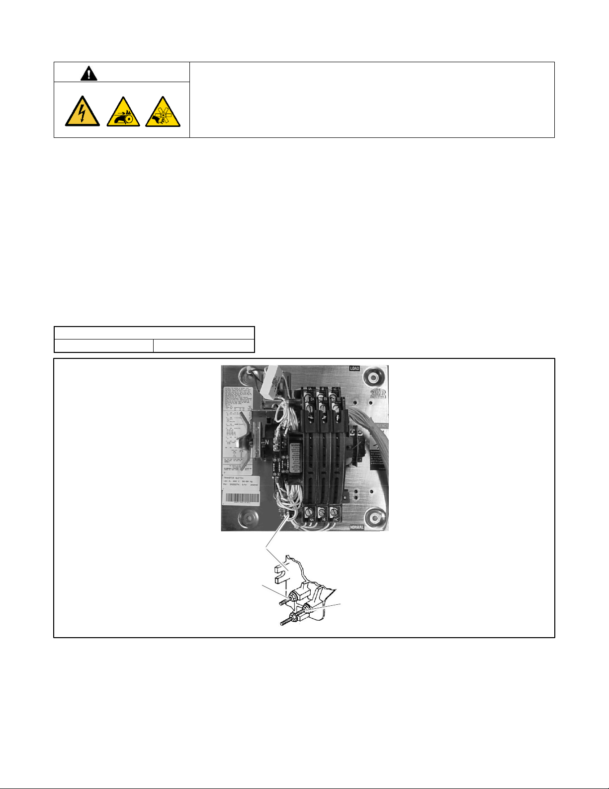
Connect the generator set remote starting circuit to the engine start connections. On 70-200 amp models, the engine start
terminals are located on the transfer switch contactor assembly and labeled with a decal. See Figure 29. On larger models, the
engine start contacts and auxiliary contacts are located on the field-connection terminal block. See Figure 30 or the transfer
switch dimension drawing for the location of the engine start contacts. Refer to the generator set installation manual for wire size
specifications.
Engine Start Contacts
Contact Rating
2 A@30 VDC/250 VAC
Figure 29 Engine Start Contacts, 70-225 Amp KUS Switches
14
Engine start contacts 14 and 15
16 (do not use)
15
6126
Page 39
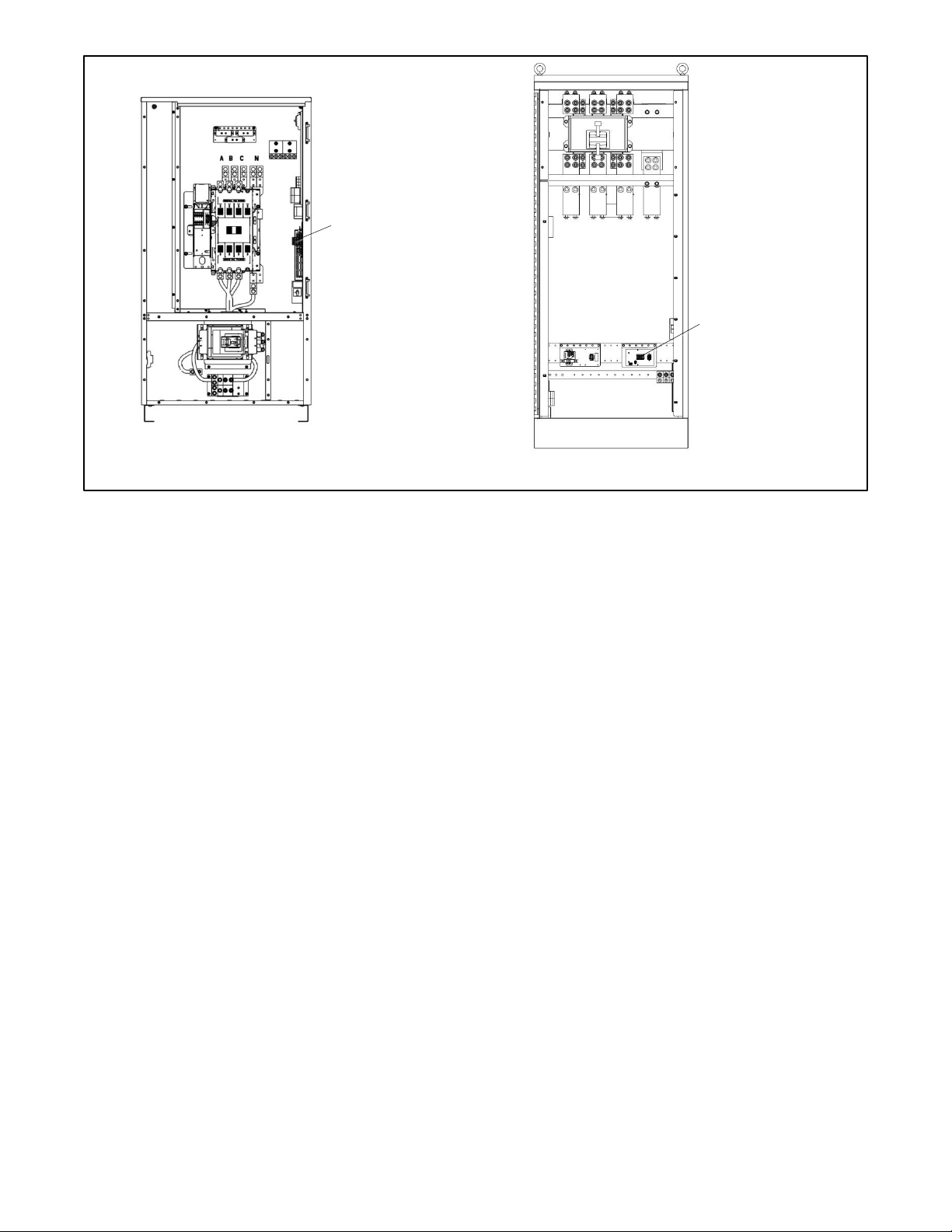
TP-7280 1/24 39
Figure 30 Field Connection Terminal Block Locations, Typical
225-600 Amp Switches
Field connection
terminal block location
Field connection
terminal block location
1600-3000 Amp Switches
ref ADV-9984
ref ADV-9986
Page 40
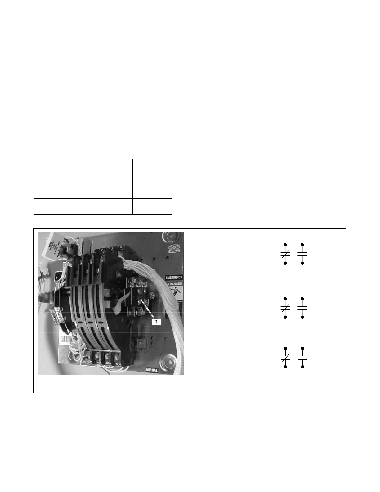
40 TP-7280 1/24
2.9.3 Auxiliary Contacts
Connect the auxiliary contacts to customer-supplied alarms, remote indicators, or other devices. Auxiliary contacts provide
contacts that close when the transfer switch is in the Normal position and contacts that close when the transfer switch is in the
Emergency position.
Figure 31 lists the number of contacts available by ATS model and size (amps).
• On 70-225 Amp units, the contacts are located on the right side of the contactor. See Figure 32.
• On 225 A/600 V and 250-4000Amp units, the contacts are located on the field connection terminal block. See the figure
titled: Field Connection Terminal Block Locations, Typical. See Figure 34 for typical connections.
Refer to the wiring diagrams provided with the transfer switch for specific auxiliary contact connection information.
Follow the wire size and tightening torque specifications shown on the decal on the transfer switch.
Auxiliary Position Indicating Contacts
(rated 10 amps @ 32 VDC/480 VAC)
Switch Rating, amps
Number of Contacts Indicating
Normal, Emergency
KUS
KUP
70-150
2, 2 — 150-225
2, 2
8, 8
225 (600 V)
8, 8
8, 8
260-600
8, 8
8, 8
800-1200
8, 8
8, 8
1600-4000
8, 8
7, 7
Figure 31 Auxiliary Contacts
Figure 32 Auxiliary Contacts, 70-225 Amp Transfer Switches
32
STANDARD
1. Auxiliary contacts (contacts shown with contactor in Normal position)
31
30
29
12
STANDARD
13
10
11
36
OPTIONAL
35
34
33
6126
Page 41
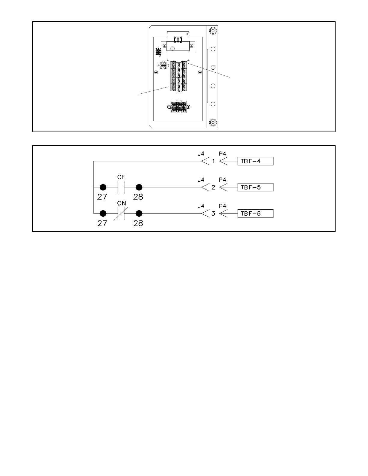
TP-7280 1/24 41
Figure 33 Field Connection Terminal Block
Figure 34 Typical Auxiliary Contact Connection, 225- 4000 Amp Transfer Switches (see schematic diagram)
Auxiliary contacts (see the schematic diagram
for contacts closed on Normal or closed on
Emergency)
Engine start contacts TBF-1 and TBF-2
ref GM14691
COMMON
GM115517
Page 42

42 TP-7280 1/24
2.10 Communication and Accessory Connections
See the Communication and Accessory Connections section for accessory and communication connection instructions.
2.11 Functional Tests
After completion of the mechanical installation and all electrical connections, perform the functional tests described in the
Functional Tests and Setup section. The procedures in the Functional Tests and Setup section are required to complete the
installation and startup of the transfer switch.
Page 43

TP-7280 1/24 43
Section 3. Three-Source Systems
3.1 Three-Source Systems
The Decision-Maker® MPAC 1500 controller is required for three-source systems.
A three-source system provides the means to connect a utility and two generators to a single load. See the figure titled: Three-
Source System Diagram and Operation. Two generators and two transfer switches are required.
Note:
The second transfer switch (ATS2) requires an external battery supply module (EBSM) to provide power to the controller. See
the External Battery Supply Module (EBSM) section.
During normal operation, the utility source supplies the load with power. In the event of a utility failure, generator set G1 or G2
will supply the load as described in the Three Source Engine Start Mode and Preferred Source Toggle sections.
3.2 Three Source Engine Start Mode
There are two modes of operation for three-source engine start. Select Mode 1 or Mode 2 on ATS2 as needed for the application.
3.2.1 Mode 1
In mode 1 there will be an attempt to start only the preferred source generator. If the preferred source does not achieve voltage
and frequency within a fail to acquire time period, the standby engine start contact will close. The fail to acquire will be indicated.
If the standby source subsequently fails to achieve voltage and frequency, a separate fail to acquire standby will be indicated.
3.2.2 Mode 2
In mode 2 both generators receive a start signal simultaneously. The ATS2 will transfer to the first generator set to reach proper
voltage and frequency. If the first source to reach available status is the preferred source, the engine start signal to the standby
source will open immediately. If the standby source is the first to reach available status, the contactor will transfer to the standby
position. When the preferred source generator output reaches available status, the controller will transfer to the preferred source
and open the engine start contacts to the standby generator (after the cooldown delay has elapsed).
3.3 Preferred Source Toggle
The preferred source toggle function alternates between the two generator sets each time the three-source function is activated.
If G1 is the preferred source during the first run, then G2 will be preferred during the next run. The preferred source selection
will continue to alternate between G1 and G2 for each subsequent run.
Page 44

44 TP-7280 1/24
3.4 Three Source System Test and Exercise
3.4.1 Unloaded Test
Unloaded testing is possible at each transfer switch. Initiating the unloaded test function at ATS1 starts and runs the preferred
generator set attached to ATS2. Initiating the unloaded test function at ATS2 starts and runs the standby generator set.
3.4.2 Loaded Test
Loaded testing is also allowed at each transfer switch. Loaded testing of the standby generator set is only possible during a
loaded test from ATS1 because the standby generator can only be connected to the load when ATS1 is connected to emergency.
To initiate a loaded test of the standby generator set, first use ATS1 to start a loaded test of the preferred source generator set.
Then use ATS2 to start a loaded test of the standby generator set.
3.4.3 Unloaded Exercise
The exercise program in ATS2 controls the operation of each generator. The exercise function does not require interaction with
ATS1. If the utility is lost during an unloaded exercise event, the event is canceled and the load is transferred to the preferred
generator set.
3.4.4 Loaded Exercise
The exercise program in ATS2 controls the operation of each generator. The loaded exercise event requires synchronization
with a loaded exercise from ATS1. Program the ATS1 exercise to start before the ATS2 exercise. Set the ATS2 exercise to end
before the ATS1 exercise ends. If the utility is lost during a loaded exercise event, the event is canceled and the load is
transferred to the preferred generator set.
Page 45
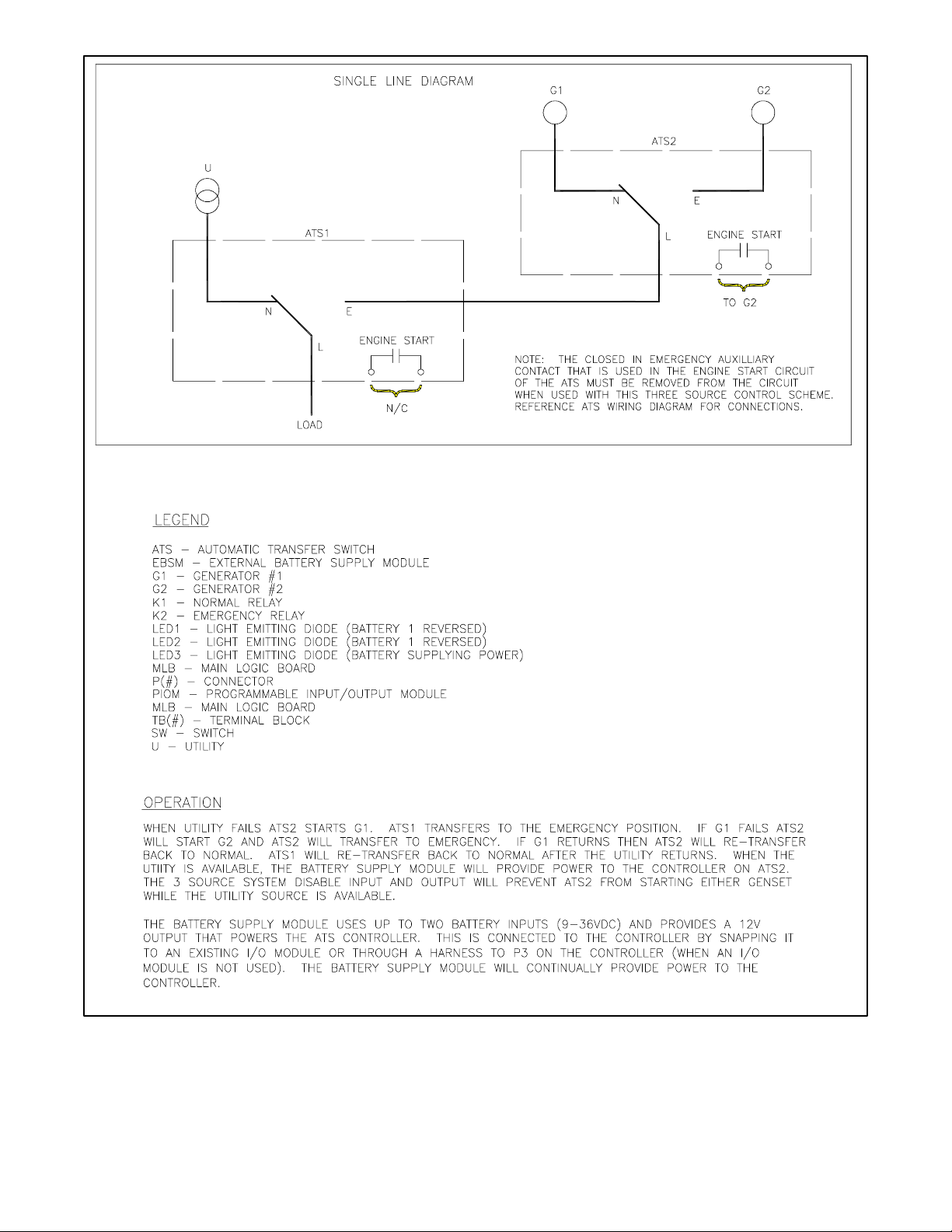
TP-7280 1/24 45
Figure 35 Three-Source System Diagram and Operation
refGM52678
Note:
ATS2 requires an external battery module to
maintain power to the controller.
Page 46
46 TP-7280 1/24
3.5 Three-Source System Connection
DANGER
Hazardous voltage.
Will cause severe injury or death.
Disconnect all power sources before opening the enclosure.
Servicing the transfer switch. Hazardous voltage will cause severe injury or death. Deenergize all power sources before
servicing. Turn off the main circuit breakers of all transfer switch power sources and disable all generator sets as follows: (1)
Press the generator set off/reset button to shut down the generator set. (2) Disconnect power to all battery chargers. (3)
Disconnect all battery cables, negative (–) leads first. Reconnect negative (–) leads last when reconnecting the battery cables
after servicing. Follow these precautions to prevent the starting of generator sets by an automatic transfer switch, remote
start/stop switch, or engine start command from a remote computer. Before servicing any components inside the enclosure: (1)
Remove all jewelry. (2) Stand on a dry, approved electrically insulated mat. (3) Test circuits with a voltmeter to verify that they
are deenergized.
Making line or auxiliary connections. Hazardous voltage will cause severe injury or death. To prevent electrical shock
deenergize the normal power source before making any line or auxiliary connections.
See Figure 36 and Figure 37 for connections during the following steps.
1. Connect the power sources to the transfer switches as described below. Refer to the transfer switch
operation/installation manual or specification sheet for cable sizes. See Figure 36 for connections.
a. Connect the utility power source to the normal side of ATS1.
b. Connect the load to the load side of ATS1.
c. Connect the emergency side of ATS1 to the load side of ATS2.
d. Connect generator set 1 to the normal side of ATS2.
e. Connect generator set 2 to the emergency side of ATS2.
2. Three-source systems require the following input/ output connections to control the engine start commands for
generator sets 1 and 2. Observe the polarity of all connections shown in Figure 37. Use wire sizes from #14 AWG to
#20 AWG for EBSM and I/O module connections.
a. Connect the ATS2 engine start contacts to the engine start circuit on generator set 2 (G2).
Note:
See the Installation Section for the engine start contact locations. Engine start contacts are labeled with a decal.
b. Connect one ATS1 programmable output from the controller to one ATS2 main logic board programmable
input as shown in Figure 37. This I/O connection will be set to Three-Source System Disable.
c. Connect one ATS2 programmable output from the controller to the engine start connection on generator set
1 (G1). The ATS1 programmable output will be set to Source N Start Signal.
3. Connect battery power. Use #14-28 AWG wire to connect the generator set engine starting battery (or batteries) to the
BATT1 terminals on terminal block TB13 on the external battery supply module (EBSM). (Another battery(ies) can be
connected to terminals BATT2 but is not required.) Follow the marking on the board for the positive (+) and
negative (-) connections. See more details and illustrations for the External Battery Supply Module (EBSM) in the EBSM
Section of this manual.
Note:
If the battery connections are reversed, red LED1 or LED2 will light. Incorrect battery connections can damage the
battery module.
Page 47

TP-7280 1/24 47
4. Set voltage selector switch SW11-1 on the battery module (EBSM) to 12 or 24VDC.
Note:
See the External Battery Supply Module (EBSM) section for more information on the EBSM.
5. Assign the ATS1 programmable output connected in step 2b. to Three-Source System Disable.
6. Assign the following inputs and outputs for the second transfer switch.
a. Assign ATS2 controller programmable input 1 to Three-Source System Disable.
b. Assign the ATS2 controller programmable output connected in step 2c. to Source N Start Signal.
Page 48
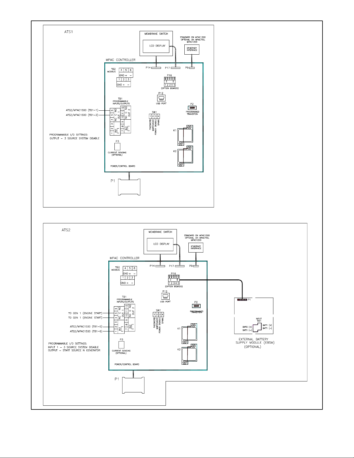
48 TP-7280 1/24
Figure 36 Three-Source System Controller Connections
refGM52678
Page 49
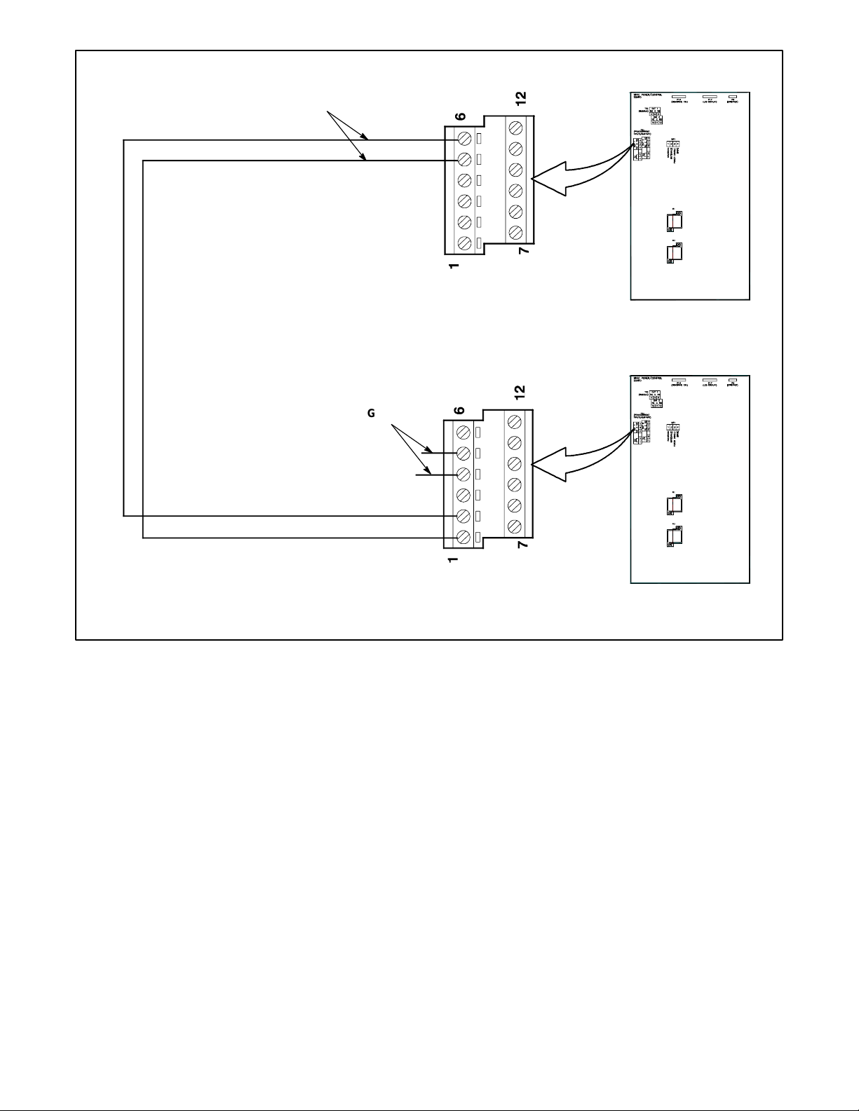
TP-7280 1/24 49
Figure 37 Input and Output Connections for Three-Source Systems
3 Source System Disable
6883
Connect the ATS2 engine start contacts (on the contactor or the fieldconnection terminal block) to G2 engine start (ES) connections. See
Figure 36
.
G1 ES
ATS1 TB1 on logic board
ATS2 TB1 on logic board
Connect Output 1 terminals
TB1-5 and TB1-6 on ATS 1 to
Input 1 terminals TB1-1 and
TB1-2 on ATS2.
Assign ATS 1 main logic board
output 1 to 3 Source System
Disable.
Assign ATS2 main logic board
input 1 to 3 Source System
Disable.
Connect one normally closed
output from ATS2 to G1 engine
start (ES) connections. Assign to
Engine Start Source N.
ATS1
ATS2
Page 50
50 TP-7280 1/24
3.6 ATS1 and ATS2 System Setup
Use the System Setup Menu on each transfer switch to set the following:
ATS1: Set the Source type to Util-Gen.
ATS2: Set the source type to Util-Gen-Gen. Set the 3 Src Engine Start Mode to Mode 1 or Mode 2 as described in the Three
Source Engine Start Mode section.
The transfer switch settings are summarized in Figure 38.
Transfer Switch
Source Type
3 Src Engine Start
Mode
Preferred Source
Toggle
Inputs
Outputs
ATS1
Util-Gen
Not Required
Not Required
Not Required
Three Source
System Disable
ATS2
Util-Gen-Gen
Mode 1 or Mode 2
Enable or Disable
Three Source
System
Source N Start
Signal
Figure 38 Transfer Switch Settings for Three-Source Systems
Page 51
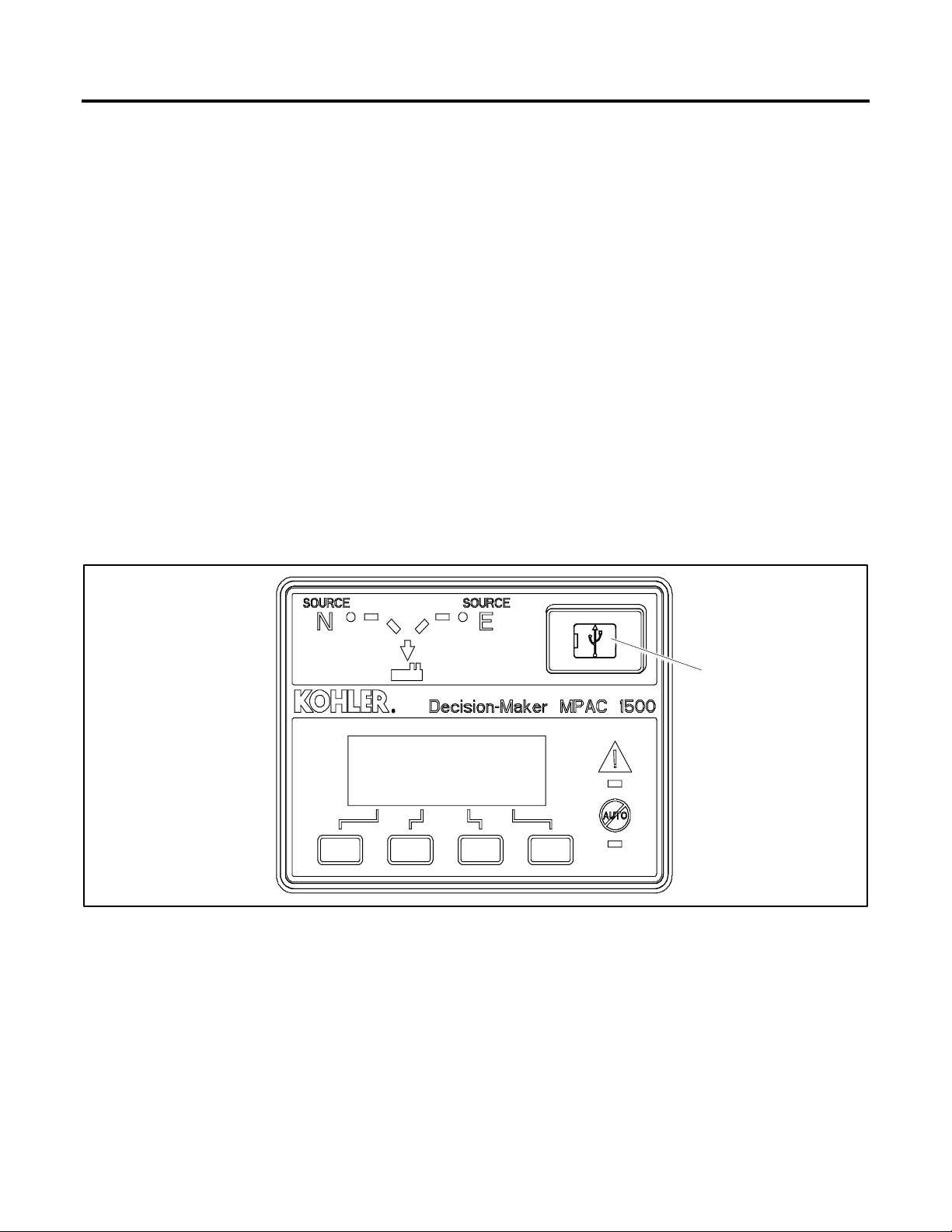
TP-7280 1/24 51
Section 4. Communication and Accessory Connections
4.1 Introduction
This section explains the connection of communication cables and factory-installed accessories.
Also refer to the following documentation for instructions to install, connect, and operate optional accessories.
• Transfer switch wiring diagrams.
• Installation instructions or diagrams provided with loose accessory kits.
4.2 Communication Connections
The Decision-Maker® MPAC 1500 controller is equipped with a USB port and a Modbus port with an
RS-485 connector. An Ethernet communication board is standard equipment on the MPAC 1500 controller
4.2.1 USB Port SiteTech Connection
A personal computer and Kohler® SiteTech™ software can be used for changing controller settings. Use a USB cable to connect
the controller to a personal computer.
See Figure 39 for the USB port location on the front of the controller assembly. Remove the small port cover and use a USB
cable with a mini-B connector to connect the controller’s USB port to the computer.
See TP-6701, SiteTech Software Operation Manual, for instructions to use the software. Disconnect the USB cable from the
controller and replace the port cover when finished.
Figure 39 USB Connection for SiteTech (MPAC 1500 controller shown)
USB connection (below
port cover)
GM85888
Page 52
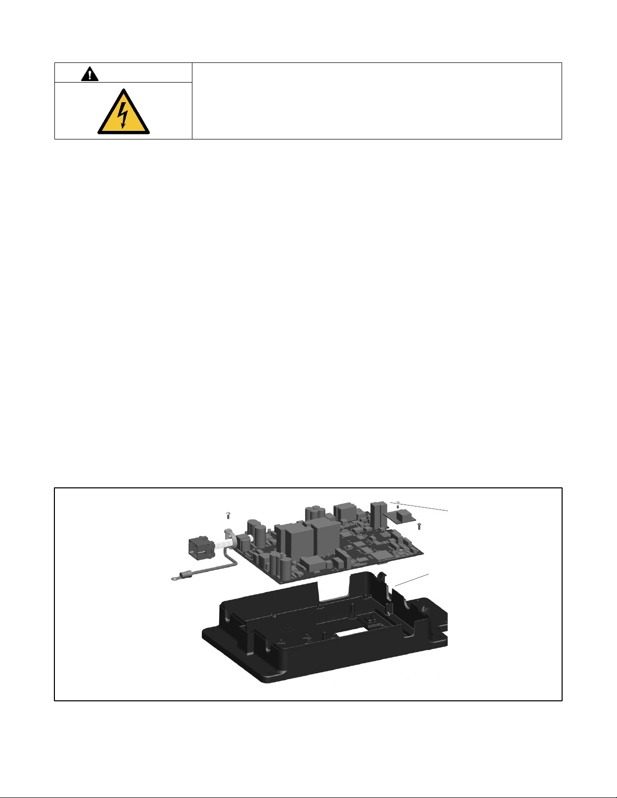
52 TP-7280 1/24
4.2.2 Modbus Connection
DANGER
Hazardous voltage.
Will cause severe injury or death.
Disconnect all power sources before opening the enclosure.
Servicing the transfer switch. Hazardous voltage will cause severe injury or death. Deenergize all power sources before
servicing. Turn off the main circuit breakers of all transfer switch power sources and disable all generator sets as follows: (1)
Press the generator set off/reset button to shut down the generator set. (2) Disconnect power to all battery chargers. (3)
Disconnect all battery cables, negative (–) leads first. Reconnect negative (–) leads last when reconnecting the battery cables
after servicing. Follow these precautions to prevent the starting of generator sets by an automatic transfer switch, remote
start/stop switch, or engine start command from a remote computer. Before servicing any components inside the enclosure: (1)
Remove all jewelry. (2) Stand on a dry, approved electrically insulated mat. (3) Test circuits with a voltmeter to verify that they
are deenergized.
See Figure 40 for the RS-485 Modbus connector location.
Use serial connections to TB2 on the controller to connect the transfer switch to a personal computer for system monitoring, the
optional remote annunciator, or a Modbus network. See Figure 42.
Notice that a 121 ohm terminating resistor is recommended on the last device in a network. If there is only one device, a
terminating resistor may be required depending on the cable distance and communication speed. Long cables and high speeds
will increase the need for a terminating resistor.
The serial port is an isolated RS-485 port with connection speeds of 9.6, 19.2, and 57.6 kbps. Use shielded twisted-pair cable
to connect to the RS-485 connectors on the controller’s terminal strip TB2 for serial connections. For connection to a PC, use a
USB to RS-485 converter.
Connect the Modbus input and output to the terminals shown in Figure 41. Use #12-24 AWG shielded, twisted-pair wire. Belden
cable #9841 or equivalent is recommended. Connect one end of the shield to ground. Leave the other end of the shield
disconnected. Tighten the connections to 0.5 Nm (4.4 in. lb.).
Use Modbus RTU (remote terminal unit) protocol for communication through the serial port. A map of the Modbus codes for this
controller is available. Contact your local distributor/dealer.
Note:
Modbus® applications require a Modbus software driver written by a trained and qualified systems programmer.
Figure 40 Modbus Connections (controller cover removed for illustration only)
Access opening for RS-485 cables
RS-485 Modbus connections
GM85884
Page 53
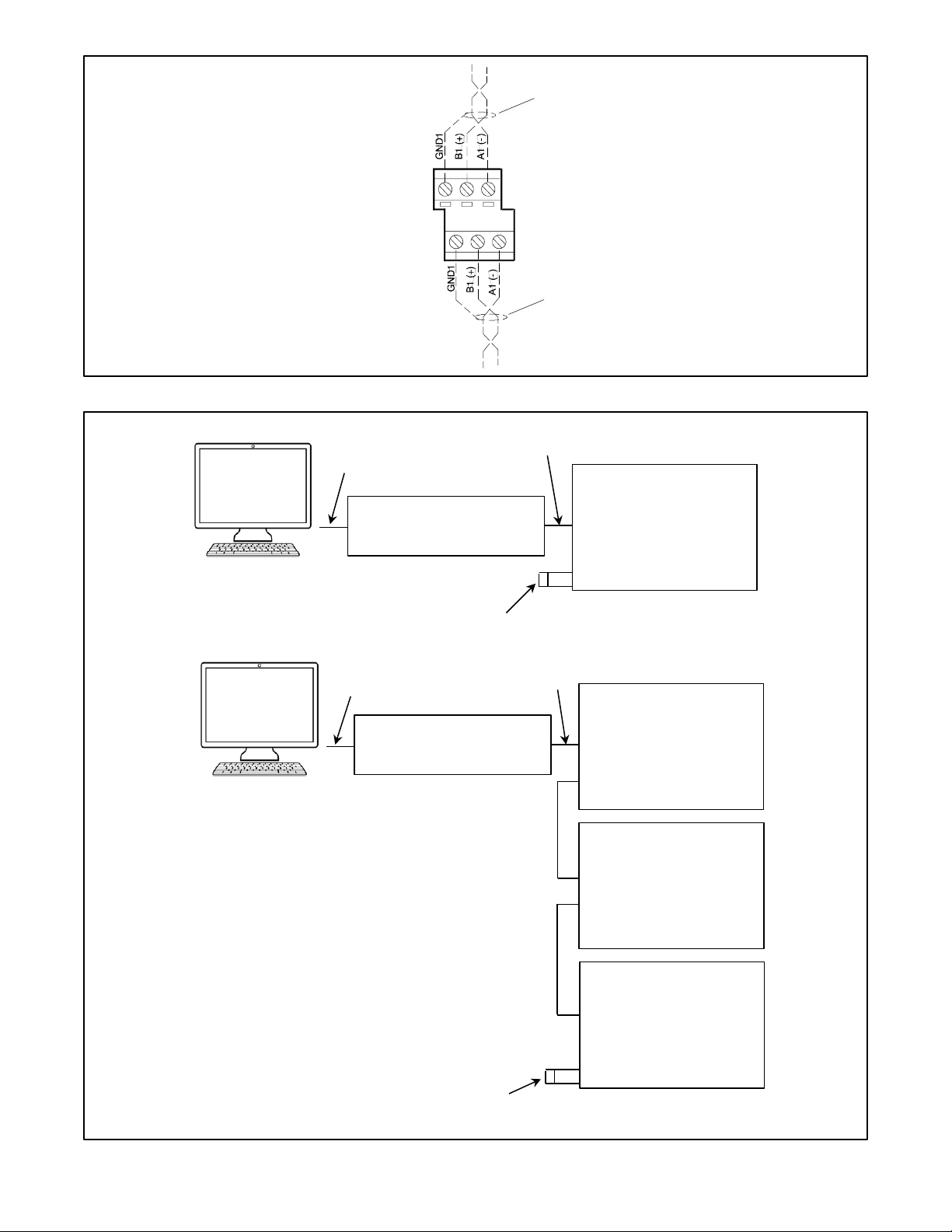
TP-7280 1/24 53
Figure 41 Modbus RS-485 Connections
TB2
3
6
1
4
Cable shield
Input
─ ─ ─ ─ Customer connections
Cable shield
Output
USB to RS-485 port converter
USB port
Use Belden #9841 or equivalent shielded, twisted-pair communication
cable for RS-485 connections. Ground one end of the cable shield.
Leave the other end of the cable shield disconnected.
†
Long cables and high communication speeds will require a terminating
resistor. Use 121 ohm resistor X-6058-27.
RS-485 *
In Device
Out
PC
Terminating resistor may be required †,
(121 Ohms)
In Device
Out
In Device
Out
Out
In Last Device
Terminating resistor may be required †,
(121 Ohms)
USB port
RS-485 *
PC
USB to RS-485 port converter
Page 54
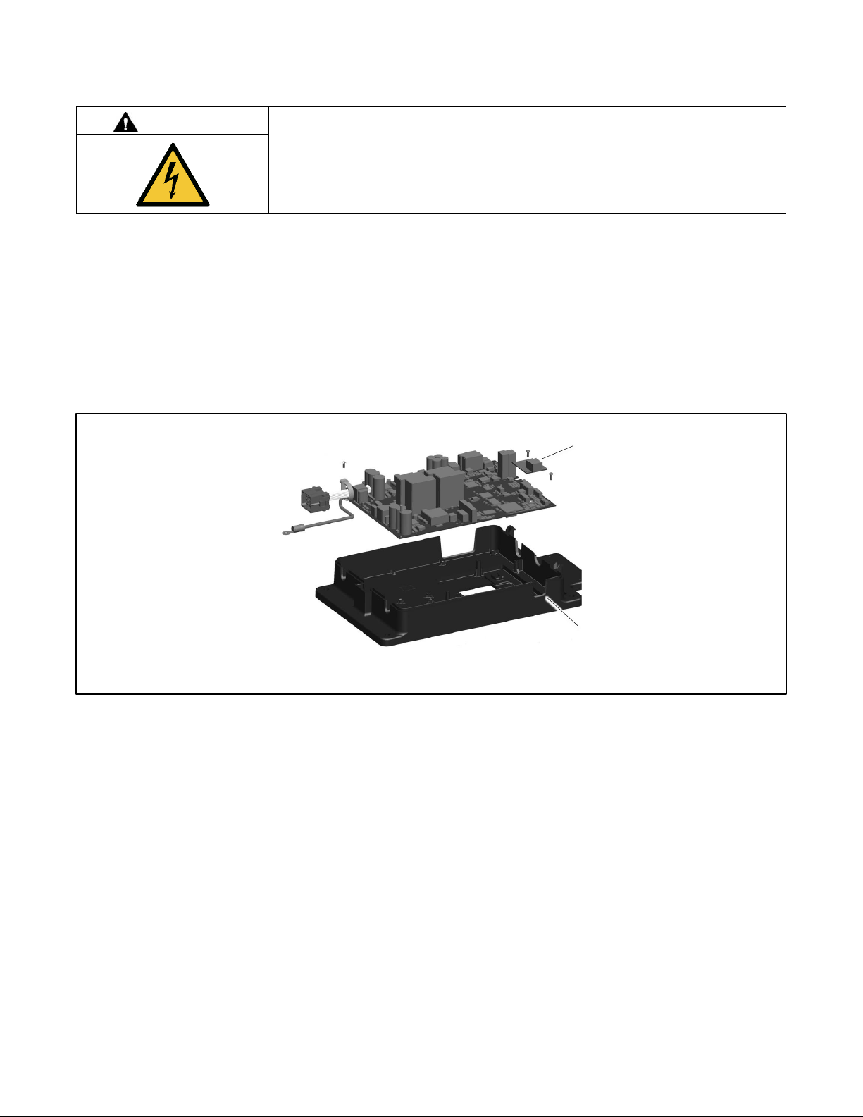
54 TP-7280 1/24
Figure 42 Serial Connections
4.2.3 Ethernet Connection
DANGER
Hazardous voltage.
Will cause severe injury or death.
Disconnect all power sources before opening the enclosure.
Servicing the transfer switch. Hazardous voltage will cause severe injury or death. Deenergize all power sources before
servicing. Turn off the main circuit breakers of all transfer switch power sources and disable all generator sets as follows: (1)
Press the generator set off/reset button to shut down the generator set. (2) Disconnect power to all battery chargers. (3)
Disconnect all battery cables, negative (–) leads first. Reconnect negative (–) leads last when reconnecting the battery cables
after servicing. Follow these precautions to prevent the starting of generator sets by an automatic transfer switch, remote
start/stop switch, or engine start command from a remote computer. Before servicing any components inside the enclosure: (1)
Remove all jewelry. (2) Stand on a dry, approved electrically insulated mat. (3) Test circuits with a voltmeter to verify that they
are deenergized.
The Ethernet communication accessory board is required for connection to the Ethernet. The Ethernet communication board is
standard on the MPAC 1500 controller. The communication board connects to the controller board as shown in Figure 43.
Figure 43 Ethernet Board (controller cover removed for illustration only)
The Ethernet communication board allows the transfer switch to be connected to a building’s Ethernet network to communicate
with personal computers connected to the same subnet.
Note:
For an ethernet connection, obtain an IP address and subnet mask number from the local system administrator.
Ethernet Port. The ethernet port is a standard RJ-45 jack. See Figure 43 for the location of the Ethernet port. Use Category 5e
or better cable to connect the controller to the building’s network.
Use the controller’s Setup menus or a personal computer connected to the controller’s USB port and Kohler SiteTech software
to set the communication parameters. The Ethernet communication board may have a default IP address assigned at the factory
for test purposes. See Figure 44. Change the IP address to an address owned by the user. See the controller operation
manual for instructions to set the communication parameters.
The transfer switch controller does not operate as a Modbus-to-Ethernet converter for other devices in a network. For multiple
device networks connected to the personal computer through the Ethernet, use a Modbus-to-Ethernet converter for the other
devices in the network. See Figure 45 and instruction sheet TT-1405, provided with the converter, for connection instructions.
The controller can communicate with up to five (5) simultaneous TCP/IP (ethernet) connections. These five connections do not
include the RS-485 serial port. In the extreme case, five users may be communicating with the controller via TCP/IP network
Ethernet communication board with
RJ-45 connector
Access opening for Ethernet
cable
GM85884
Page 55
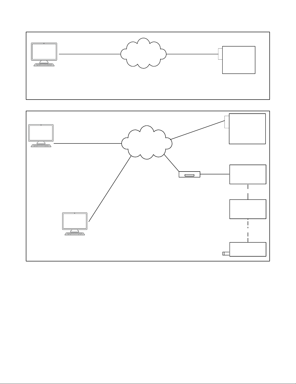
TP-7280 1/24 55
connections and another may be communicating through the serial port, for a total of six (6) communication channels. As the
controller is asked to communicate with more and more outside devices, the communication will slow down.
Figure 44 Remote Network (Ethernet) Connection
Figure 45 Ethernet Connections to Multiple-Device Network
Ethernet
Network
MPAC
Controller with
Ethernet comm.
board
IP xx.xx.xx.03
Note:
The PC and the ATS must be on the same subnet.
Note:
A crossover cable can be used to connect the PC to the ATS controller through the Ethernet port.
Modbus® TCP/IP
Category 5e
Modbus® TCP/IP
Category 5e
PC
IP xx.xx.xx.02
Ethernet
Network
MPAC
Controller with
Ethernet comm.
board
IP xx.xx.xx.03
Terminating resistor
(121 Ohms)
Device
Device
Last Device
RS-485
RS-485
Converter,
Modbus®/Ethernet
IP xx.xx.xx.05
Modbus®
RTU
RS-485
Modbus® TCP/IP
Category 5e
Modbus® TCP/IP
Category 5e
Modbus® TCP/IP
Category 5e
PC
IP xx.xx.xx.02
PC
IP xx.xx.xx.01
Modbus®
TCP/IP
Page 56
56 TP-7280 1/24
4.3 Accessory Modules
DANGER
Hazardous voltage.
Will cause severe injury or death.
Disconnect all power sources before opening the enclosure.
Servicing the transfer switch. Hazardous voltage will cause severe injury or death. Deenergize all power sources before
servicing. Turn off the main circuit breakers of all transfer switch power sources and disable all generator sets as follows: (1)
Press the generator set off/reset button to shut down the generator set. (2) Disconnect power to all battery chargers. (3)
Disconnect all battery cables, negative (–) leads first. Reconnect negative (–) leads last when reconnecting the battery cables
after servicing. Follow these precautions to prevent the starting of generator sets by an automatic transfer switch, remote
start/stop switch, or engine start command from a remote computer. Before servicing any components inside the enclosure: (1)
Remove all jewelry. (2) Stand on a dry, approved electrically insulated mat. (3) Test circuits with a voltmeter to verify that they
are deenergized.
This section provides specifications and field connection information for factory-installed accessory modules. If the modules are
not factory-installed, follow the instructions provided with the kits to install the mounting assembly and modules.
The transfer switch uses a standard bus system for connecting accessory modules to the controller. This bus incorporates a
standard serial communication interface for passing data back and forth between the main logic board and the assemblies on
the expansion bus.
The module mounting kit holds up to five optional modules. The total current draw of all modules must not exceed 300 mA. See
Figure 46. Add the current draw for every module installed to determine the total current draw. If an External Battery Module is
installed and connected to a battery, there is no current restriction. The External Battery Module, if used, must be the last board
on the bus.
Module Current Draw Specifications, mA
Alarm Module
75
Standard I/O Module
75
High Power I/O Module
100
Figure 46 Option Board Types
4.3.1 Accessory Module Mounting
Mount the accessory modules on the module mounting plate. Starting at the end of the module mounting assembly nearest the
cable connection, install any I/O modules first, then install the alarm board, if used. The external battery module, if used, must
be the last module. See Figure 47. The alarm board has a fixed Modbus address = 5.
Note:
Some models may have the I/O module assembly installed with the cable connection end pointing to the side or the bottom.
Regardless of the actual orientation of the assembly, the I/O modules must be installed closest to the cable connection, followed
by the alarm module and then the external battery module, if used.
Page 57
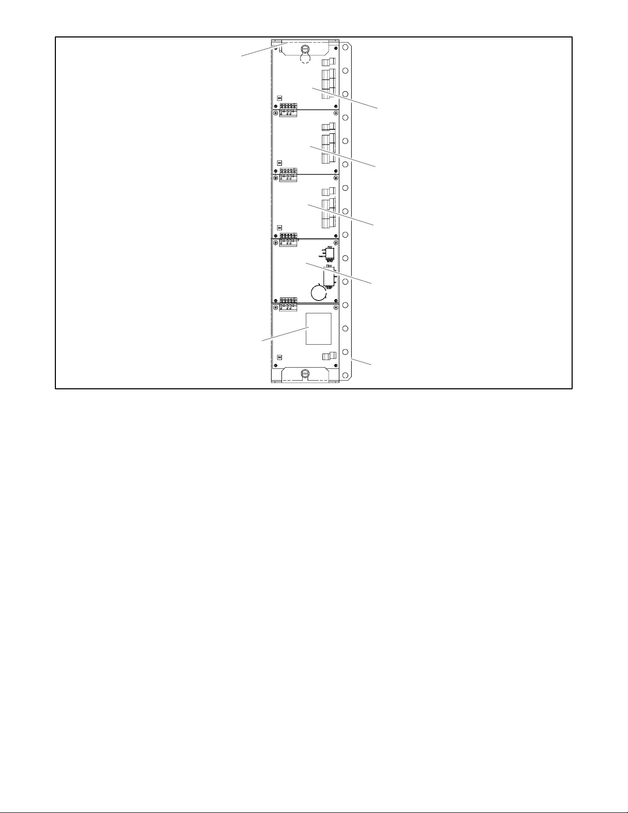
TP-7280 1/24 57
Figure 47 Module Mounting
Cable connection (defined as the TOP
regardless of orientation)
I/O modules (if equipped)
GM46258
I/O modules (if equipped)
I/O modules (if equipped)
Alarm module (if equipped)
Mounting plate
External battery module (must be last, if equipped)
Page 58
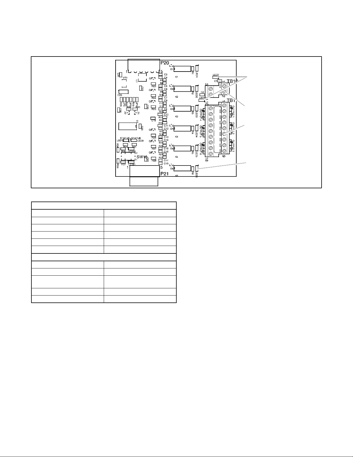
58 TP-7280 1/24
4.3.2 Input/Output (I/O) Modules
Two types of input/output modules are available. The standard I/O Module has two inputs and six outputs. The high-power I/O
module has two inputs and three outputs. See Figure 48 through Figure 51 for I/O module illustrations and specifications.
Figure 48 Standard Input/Output Module
Inputs
Available Inputs
2
Input Definition
Contact Closure
Current
5 mA Max
Connection Type
Terminal Strip
Wire Size
#14-24 AWG
Max Distance
700 feet
Outputs
Outputs Available
6
Contact Type
Form C (SPDT)
Contact Voltage Rating
2 A @ 30 VDC
500 mA @ 125 VAC
Connection Type
Terminal Strip
Wire Size
#14-24 AWG
Figure 49 Standard I/O Module Specifications
Output LEDs 1-6
Output connector
GM41093
Input connector (Figure 52)
Input LEDs 7 and 8 for inputs 1
and 2
Page 59
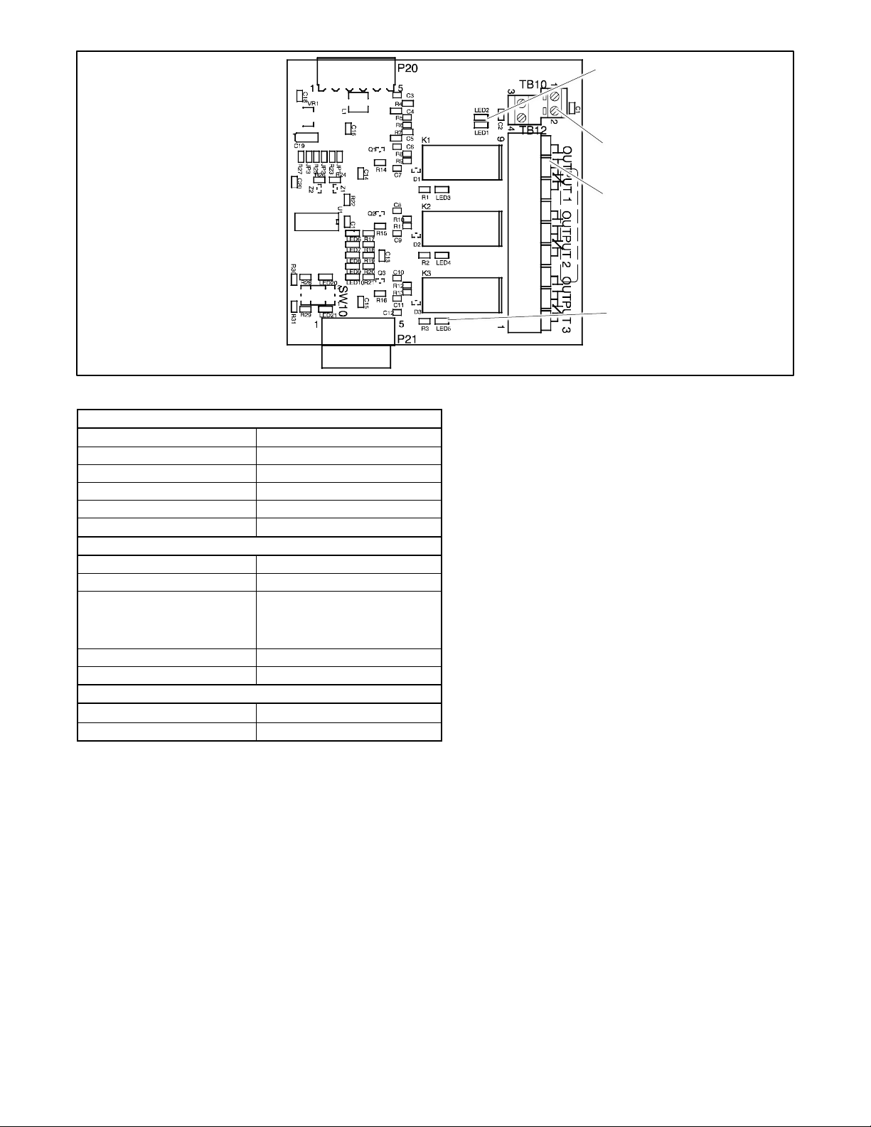
TP-7280 1/24 59
Figure 50 High-Power Input/Output Module
Inputs
Available Inputs
2
Input Definition
Contact Closure
Current
5 mA Max
Connection Type
Terminal Strip
Wire Size
#14-24 AWG
Max Distance
700 feet
Outputs
Outputs Available
3
Contact Type
Form C (SPDT)
Contact Voltage Rating
12 A @ 24 VDC
12 A @ 250 VAC
10 A @ 277 VAC
2 A @ 480 VAC
Connection Type
Terminal Strip
Wire Size
#14-24 AWG
Environmental Specifications
Temperature
-40C to 85C (-104F to 185F)
Humidity
35% to 85% noncondensing
Figure 51 High-Power I/O Module Specifications
Use 14-24 AWG cable to connect to inputs and outputs. See Figure 52.
LEDs on the module circuit board light to indicate that each input or output is active.
Note:
Each I/O module must have unique address.
Use the address DIP switches on the I/O module to assign a unique (different) address to each module as shown in Figure 53.
Assign addresses in order from 1 to 4. An LED for each DIP switch lights to indicate that the switch is closed.
The alarm module’s fixed address is 5. The battery module’s fixed address is 6.
See the controller operation manual for instructions to assign functions to each input and output. Inputs and outputs can also be
assigned using a personal computer with Kohler® SiteTech™ software or over Modbus. See TP-6701, SiteTech Operation
Manual, or TP-6113, Modbus Protocol Manual.
Output LEDs 3-5 for outputs 1, 2,
and 3
Output connector
GM42186
Input connector (Figure 52)
Input LEDs 1 and 2
Page 60
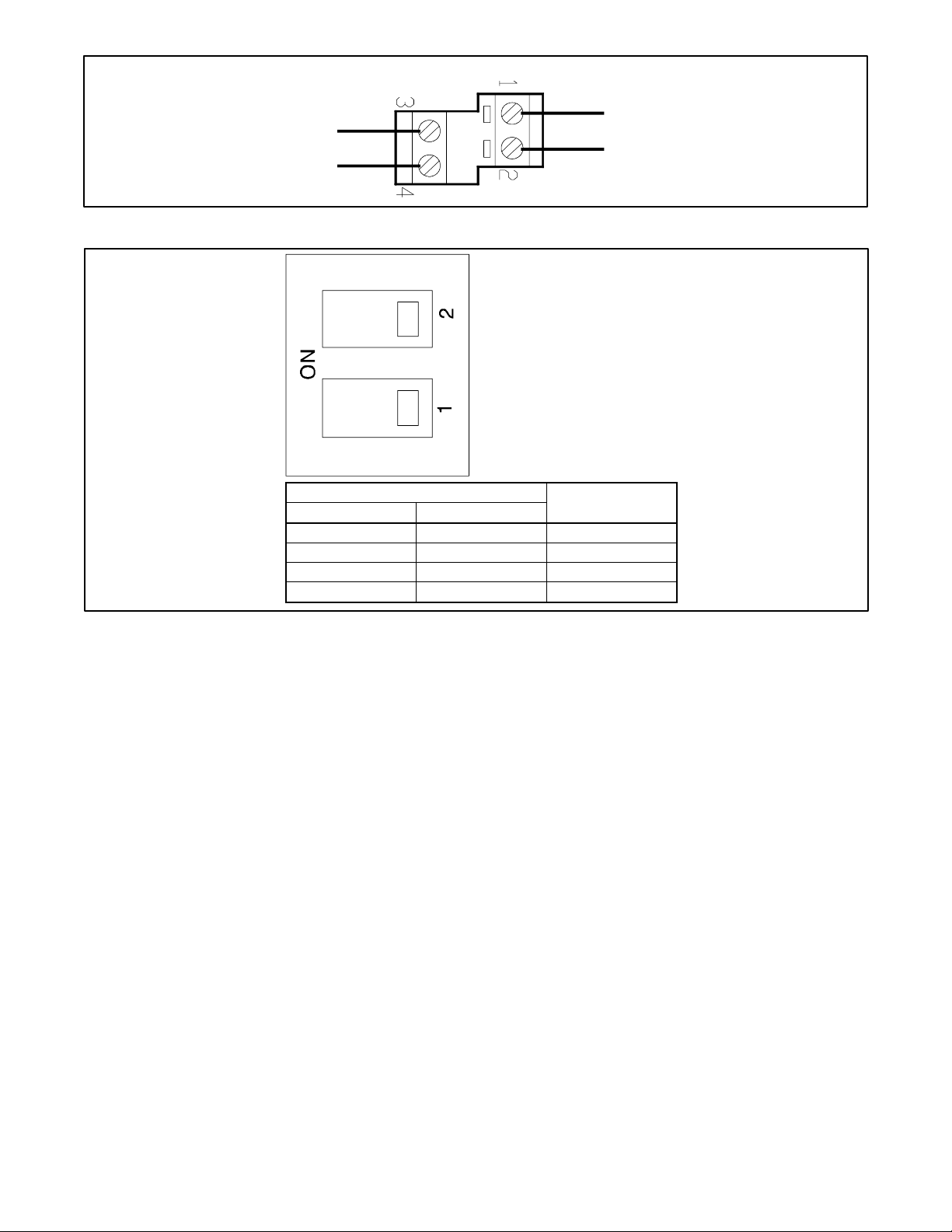
60 TP-7280 1/24
Figure 52 I/O Module Input Connections (TB1 or TB10)
DIP Switch
Address
1
2
Off
Off 1 On
Off 2 Off
On 3 On
On
4
Figure 53 Address DIP Switch Settings
refGM41093
INPUT 1
INPUT 2
Address=1 shown
Both switches OFF
Page 61
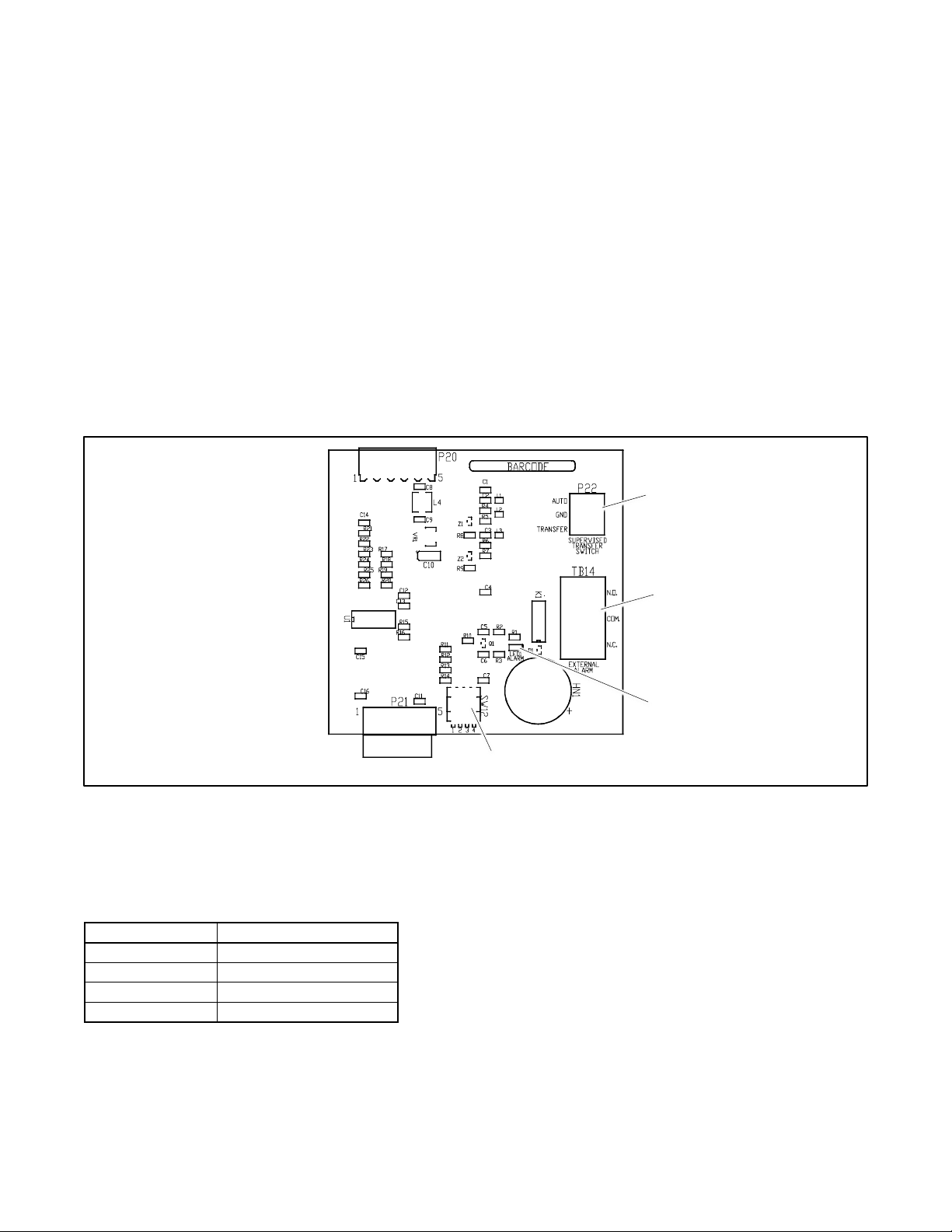
TP-7280 1/24 61
4.3.3 External Battery Supply Module (EBSM)
The External Battery Supply Module is standard factory-installed equipment on Model KUS and KUP service entrance transfer
switches. The installer must connect the generator set engine starting batteries or other batteries to the EBSM. See the
installation section for instructions.
4.3.4 Alarm Module
See Figure 54 for the optional alarm module. A module mounting kit is required for installation of the alarm module. See the
Accessory Module Mounting section.
The functions provided by this board are:
• 90 dB Audible alarm (any alarm function can be programmed to trigger the audible alarm)
• Chicago alarm operation
• Preferred source selection
• Supervised transfer control (supervised transfer control switch not available for Models KUS/KUP)
• Connection for external alarm
The alarm board has a fixed address = 5.
Figure 54 Alarm Module
Alarm Board DIP Switches
There are four DIP switches on the alarm module board. Some of the switches are not used. See Figure 55. To enable the
preferred source selection, set DIP switch 1 to ON. If the supervised transfer switch is installed on the ATS, set DIP switch 2 to
ON.
DIP Switch
Function
1
Preferred source selection
2
Supervised transfer enable
3
Not used
4
Not used
Figure 55 Alarm Board DIP Switches
Alarm Indicator, LED1
DIP Switches
External Alarm Connection, TB 14
Supervised Transfer Switch
Connection, P22 (N/A KUS/KUP)
GM40764
Page 62
62 TP-7280 1/24
Preferred Source Selection
The alarm module is required for preferred source selection. To enable the preferred source selection, set DIP switch 1 to ON.
Then see the controller operation manual for instructions to select Source N or Source E as the preferred source.
External Alarm
A customer-supplied external alarm horn can be connected to the alarm module at terminal block TB14. Connect to the normally
open or normally closed contact as recommended by the alarm manufacturer’s instructions. See Figure 56.
Item
Specification
Wire Size
#12-22 AWG Cu
Contact Voltage Rating
500 mA @ 120 VAC
250 mA @ 240 VAC
Figure 56 External Alarm Connection Specifications
Audible Alarm Setup
The alarm board is equipped with a 90 dB audible alarm. The audible alarm can be set to sound under selected fault conditions.
Use the Common Alarms Setup menu to assign functions to the audible alarm. See the controller operation manual for
instructions to set Audible Alarm: Y for each function that should trigger the alarm.
Alarm Operation, Normal Mode
In Normal Mode, the horn sounds anytime a fault event happens in the system. The horn continues to sound unless the alarm
silence button is pressed. When the fault is cleared, the alarm silence is ended and reset for the next alarm.
Alarm Operation, Chicago Alarm Mode
Chicago Alarm mode requires the horn to sound and a lamp or LED to light when the switch is in the emergency (non-preferred)
position. The horn continues to sound unless the alarm silence button is pressed. When the fault is cleared, the alarm silence is
ended and reset for the next alarm.
For Chicago Alarm Mode, use the Common Alarm Setup menu to assign the necessary faults and conditions to the audible
alarm. See the controller operation manual for instructions to assign common faults. Be sure to assign the Contactor in Standby
condition to trigger the audible alarm.
A remote alarm or indicator light can also be connected to the alarm board to indicate the alarm condition, as described
previously. See External Alarm.
Alarm Silence Mode
In Alarm Silence Mode, the horn is disabled. Alarm Silenced appears on the display and the system alert LED lights.
The Alarm Silenced condition can be assigned to a programmable output. See the controller operation manual for instructions
to assign outputs.
Instructions to Silence the Alarm in Normal and Chicago Alarm Modes
When the alarm is activated, the word Alarm appears on the main display menu above the first button. See Figure 57. Press the
Alarm button to open the Reset menu. Then press the button labeled Reset to silence the alarm.
Page 63
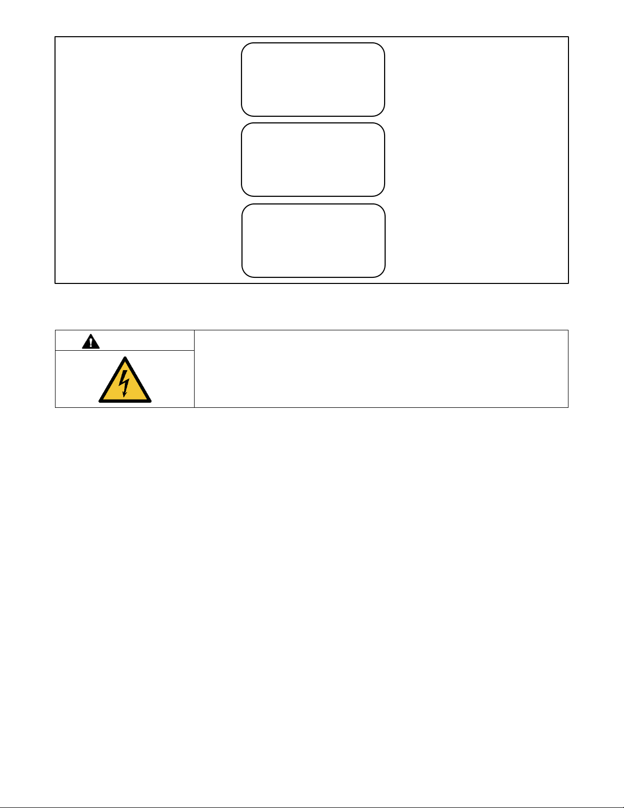
TP-7280 1/24 63
Figure 57 Alarm Silence
4.4 Load Shed (Forced Transfer to OFF)
DANGER
Hazardous voltage.
Will cause severe injury or death.
Disconnect all power sources before opening the enclosure.
Servicing the transfer switch. Hazardous voltage will cause severe injury or death. Deenergize all power sources before
servicing. Turn off the main circuit breakers of all transfer switch power sources and disable all generator sets as follows: (1)
Move all generator set master controller switches to the OFF position. (2) Disconnect power to all battery chargers. (3)
Disconnect all battery cables, negative (–) leads first. Reconnect negative (–) leads last when reconnecting the battery cables
after servicing. Follow these precautions to prevent the starting of generator sets by an automatic transfer switch, remote
start/stop switch, or engine start command from a remote computer. Before servicing any components inside the enclosure: (1)
Remove all jewelry. (2) Stand on a dry, approved electrically insulated mat. (3) Test circuits with a voltmeter to verify that they
are deenergized.
The load shed (forced transfer to OFF) accessory is available for programmed-transition and closed-transition transfer switches.
The load shed accessory is available factory-installed or as a loose kit. For kit installation, refer to the Installation Instructions
provided with the kit.
See Figure 58 for an illustration of the load shed accessory.
Connection and Setup
The load shed function requires an external signal (contact closure) to initiate transfer to the OFF position. Connect the external
contact to input #1 (if available) or input #2 on connector TB1 on the main logic board. See Figure 59. Use #12-24 AWG wire
and tighten to 0.5 Nm (4.4 in. lb.).
Alternatively, the external contact can be connected to an input connection on an optional I/O module.
Use the Input/Output setup menu or Kohler SiteTech software to assign the connected input (Main Board Input #1 or #2, or an
input on the I/O module) to the forced transfer to off function.
▼ ▲ Reset Main
System Ready
LD Exer 12/14 @ 16:00
Norm 480V Emer 480V
Reset
To Silence Alarm
Alarm View Set Test
▼ ▲ Reset Main
Reset
Status or Fault Description
Alarm Silenced
Page 64
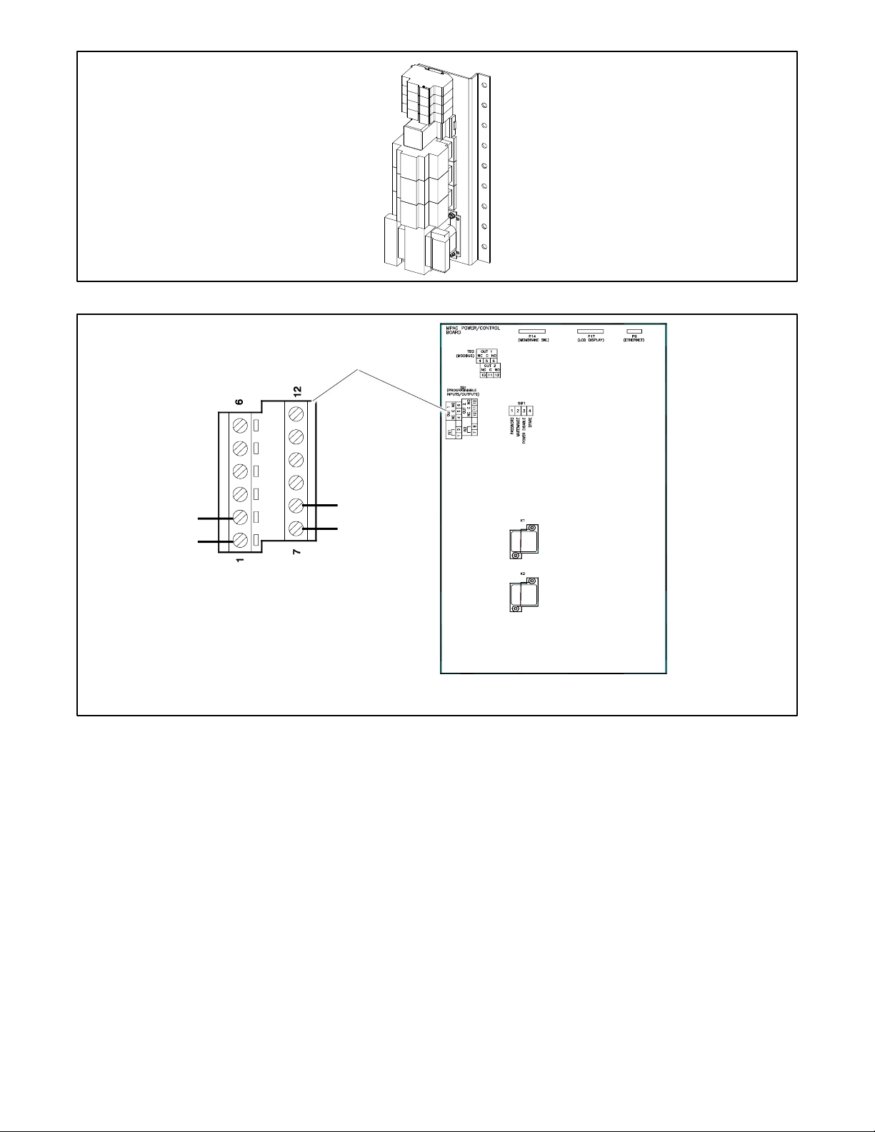
64 TP-7280 1/24
Figure 58 Load Shed Accessory (for identification)
Figure 59 Forced Transfer to Off Input Connection (for factory-installed load shed kits)
GM23469
Input/output terminal strip TB1
GM89713
#12-24 AWG wire 0.5 Nm (4.4 in. lb.)
MLB Input 2
(alternate
connection)
MLB
Input 2
TB1
MPAC Controller Circuit Board
Page 65
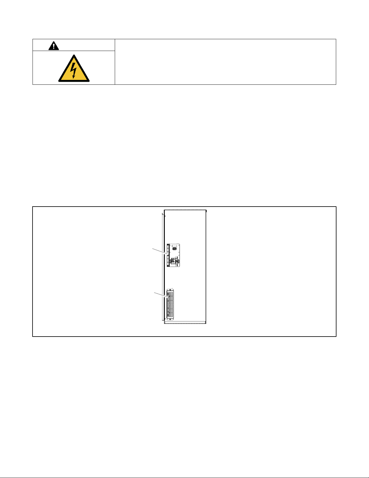
TP-7280 1/24 65
4.5 Heater
DANGER
Hazardous voltage.
Will cause severe injury or death.
Disconnect all power sources before opening the enclosure.
Servicing the transfer switch. Hazardous voltage will cause severe injury or death. Deenergize all power sources before
servicing. Turn off the main circuit breakers of all transfer switch power sources and disable all generator sets as follows: (1)
Move all generator set master controller switches to the OFF position. (2) Disconnect power to all battery chargers. (3)
Disconnect all battery cables, negative (–) leads first. Reconnect negative (–) leads last when reconnecting the battery cables
after servicing. Follow these precautions to prevent the starting of generator sets by an automatic transfer switch, remote
start/stop switch, or engine start command from a remote computer. Before servicing any components inside the enclosure: (1)
Remove all jewelry. (2) Stand on a dry, approved electrically insulated mat. (3) Test circuits with a voltmeter to verify that they
are deenergized.
An anti-condensation heater kit is available. The strip heater is controlled by a hygrostat to raise the temperature inside the
enclosure above the dewpoint to prevent condensation. Figure 60 shows a typical location of the heater kit components inside
the enclosure.
The installer must connect 120 VAC power to the terminal block near the hygrostat. See Figure 61 and Figure 62. The heater
and hygrostat are connected to power through a 15-amp circuit breaker.
The relative humidity setting on the hygrostat is adjustable from 35% to 95%. A setting of 65% is recommended.
Figure 60 Heater Location, Typical
Hygrostat assembly, see Figure 61
Strip heater with guard
Right Side View
GM69824
Page 66
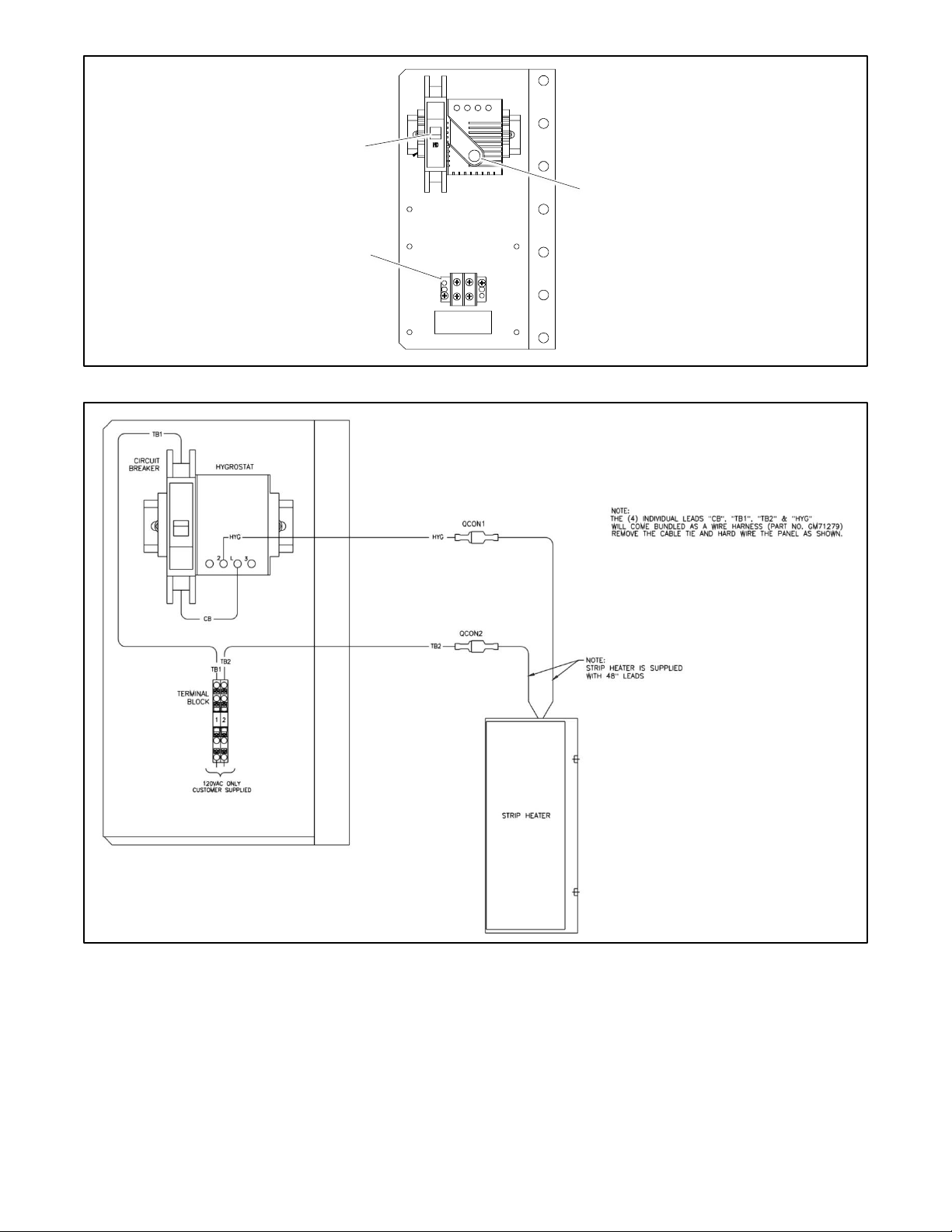
66 TP-7280 1/24
Figure 61 Hygrostat Assembly, Typical
Figure 62 Heater Connections
Circuit breaker
Relative humidity adjustment control
GM71056
120 VAC power connection terminal block
(or transformer for some kits)
GM71278C
Page 67

TP-7280 1/24 67
4.6 Engine Start Circuit Monitoring System
The optional Engine Start Circuit Monitoring System forwards engine start signals while continuously monitoring for wiring faults
(open or short circuits) as required by the electrical code NEC 700.10. If the generator module receives an engine start signal
or detects any faults, it will send the start signal to the generator and provide an alarm.
See the installation instructions provided with the kit.
4.7 Other Accessories
Refer to the following documentation for instructions to install, connect, and operate optional accessories.
• Transfer switch wiring diagrams.
• Installation instructions provided with loose accessory kits.
• Controller Operation Manual. See List of Related materials in the Introduction section of this manual for document
numbers.
Page 68

68 TP-7280 1/24
Page 69
TP-7280 1/24 69
Section 5. Scheduled Maintenance
Regular preventive maintenance ensures safe and reliable operation and extends the life of the transfer switch. Preventive
maintenance includes periodic testing, cleaning, inspection, and replacement of worn or missing components.
Have maintenance or service performed by a local authorized distributor/dealer. Maintenance and service must comply with all
applicable codes and standards. See the Service Assistance section in this manual for how to locate a local distributor/dealer.
The transfer switch controller Operation Manual contains the Service Schedule and other maintenance information. Refer to the
Operation Manual shipped with the transfer switch or see Figure 63 for the Operation Manual part number.
Keep records of all maintenance or service.
Operation Manual
Part Number
Operation Manual, Decision-Maker® MPAC 1500 Controller
TP-6883
Figure 63 Operation Manual
Page 70

70 TP-7280 1/24
Page 71

TP-7280 1/24 71
Section 6. Functional Tests and Setup
6.1 Introduction
Be sure to perform all of the functional tests described in this section before putting the transfer switch into operation.
The functional tests include the following checks:
• Manual Operation Test
• Voltage Checks
• Lamp Test
• Automatic Operation Test
Note:
Perform these checks in the order presented to avoid damaging the ATS.
Read all instructions on the labels affixed to the automatic transfer switch before proceeding.
To complete the installation, follow the instructions in this section to:
• Set the time, date, and exercise schedule on the controller.
• Perform the system startup procedures listed on the startup form.
• Register the unit using the Kohler® online Warranty Processing System.
6.2 Manual Operation Test
If you have not already done so, test the contactor manual operation before proceeding to the voltage check and electrical
operation test.
Note:
Disable the generator set and disconnect the power by opening the circuit breakers or switches for both sources before manually
operating the transfer switch.
Follow the instructions in the Installation Section to check the transfer switch manual operation.
A contactor in normal and serviceable condition transfers smoothly without binding when operated manually. Do not place the
transfer switch into service if the contactor does not operate smoothly without binding; contact an authorized distributor/dealer
to service the contactor.
Page 72
72 TP-7280 1/24
6.3 Voltage Check
The voltage, frequency, and phasing of the transfer switch and the power sources must be the same to avoid damage to loads
and the transfer switch. Compare the voltage and frequency ratings of the utility source, transfer switch, and generator set, and
verify that the ratings are all the same.
Use the voltage check procedure explained in this section to verify that the voltages and phasing of all power sources are
compatible with the transfer switch before connecting the power switching device and controller wire harnesses together.
Follow the instructions provided with the generator set to prepare the generator set for operation.
Read and understand all instructions on installation drawings and labels on the switch. Note any optional accessories that have
been furnished with the switch and review their operation.
Note:
Source N is the source connected to the normal side of the contactor. Source E is the source connected to the emergency side
of the contactor. Verify that the source leads are connected to the correct lugs before proceeding.
The voltage check procedure requires the following equipment:
• A digital voltmeter (DVM) with electrically insulated probes capable of measuring the rated voltage and frequency
• A phase rotation meter
DANGER
Hazardous voltage.
Will cause severe injury or death.
Only authorized personnel should open the enclosure.
Testing live electrical circuits. Hazardous voltage or current will cause severe injury or death. Have trained and qualified
personnel take diagnostic measurements of live circuits. Use adequately rated test equipment with electrically insulated probes
and follow the instructions of the test equipment manufacturer when performing voltage tests. Observe the following precautions
when performing voltage tests: (1) Remove all jewelry. (2) Stand on a dry, approved electrically insulated mat. (3) Do not touch
the enclosure or components inside the enclosure. (4) Be prepared for the system to operate automatically. (600 volts and under)
Page 73

TP-7280 1/24 73
Voltage Check Procedure
1. If Source N is a generator set, move the generator set master switch to the RUN position. The generator set should
start.
2. Close the Source N circuit breaker or switch.
3. Use a voltmeter to check the Source N (normal) phase-to-phase and phase-to-neutral (if applicable) terminal voltages
and frequency.
a. If Source N is the utility and the measured input does not match the voltage and frequency shown on the
transfer switch nameplate, STOP! Do not proceed further in installation because the transfer switch is not
designed for the application—call your distributor/dealer to order the correct transfer switch.
b. If Source N is a generator set and the generator set output voltage and frequency do not match the nominal
system voltage and frequency shown on the transfer switch nameplate, follow the manufacturer’s instructions
to adjust the generator set. The automatic transfer switch will only function with the rated system voltage and
frequency specified on the nameplate.
4. Use a phase rotation meter to check the phase rotation at the Source N (normal) terminals. Rewire the transfer switch
Source N terminals to obtain the correct phase sequence if necessary.
Note:
The default setting for the phase rotation on the controller is ABC. If the application uses a phase rotation of BAC, refer
to the controller Operation Manual for instructions to change the phase rotation setting on the controller.
5. If the source is a generator set, stop the generator set by moving the master switch to the OFF position.
6. Disconnect Source N by opening upstream circuit breakers or switches.
7. Repeat steps 1 through 5 for Source E. Then proceed to step 8.
8. Disconnect both sources to the transfer switch by opening the circuit breakers or switches.
9. Close and lock the transfer switch enclosure door.
10. Reconnect both power sources by closing the circuit breakers or switches.
11. Move the generator set master switch to the AUTO position.
Note:
If the engine cooldown time delay setting is not set to zero (default setting), the generator set may start and run until
the Engine Cooldown Time Delay ends.
12. Perform the lamp test and then proceed to the automatic operation test.
6.4 Lamp Test
Refer to the controller Operation Manual for instructions to perform a lamp test. Verify that all controller LEDs or lamps light
during the test.
Page 74

74 TP-7280 1/24
6.5 Automatic Operation Test
Check the transfer switch’s automatic control system immediately after the voltage check. Refer to the controller Operation
Manual for instructions to run the automatic operation test.
Note:
Close and lock the enclosure door before starting the test procedure.
6.6 System Setup
Set the controller’s current time and date. See the controller Operation Manual for instructions.
The transfer switch is factory-set with default settings for time delays and other parameters. See the controller Operation Manual
for instructions to view and change settings, if necessary.
Note:
Use caution when changing transfer switch settings. The source voltage and frequency settings must match the values shown
on the transfer switch nameplate.
6.7 Exerciser Setup
To maximize the reliability of the emergency power system, set the exerciser to start and run the generator set at the intervals
and load conditions recommended by the generator set manufacturer. See the controller Operation Manual for instructions.
Transfer switches equipped with the Decision-Maker® MPAC 750 controller may also use the optional programmable exerciser.
Refer to the instructions provided with the exerciser to schedule additional loaded or unloaded exercise runs.
6.8 User Interface Cover
The gasket-sealed, hinged user interface cover prevents unauthorized access to the transfer switch controls and protects the
user interface from harsh environmental conditions. The cover is available as an optional accessory for NEMA 1 enclosures.
NEMA 3R enclosures include the cover as standard equipment.
Use a customer-supplied padlock to lock the cover.
6.9 Startup Notification
Perform the system startup procedure explained on the Startup Notification Form. The Startup Notification Form covers all
equipment in the power system. Complete the Startup Notification Form and register the power system using the Kohler® online
Warranty Processing System.
Page 75
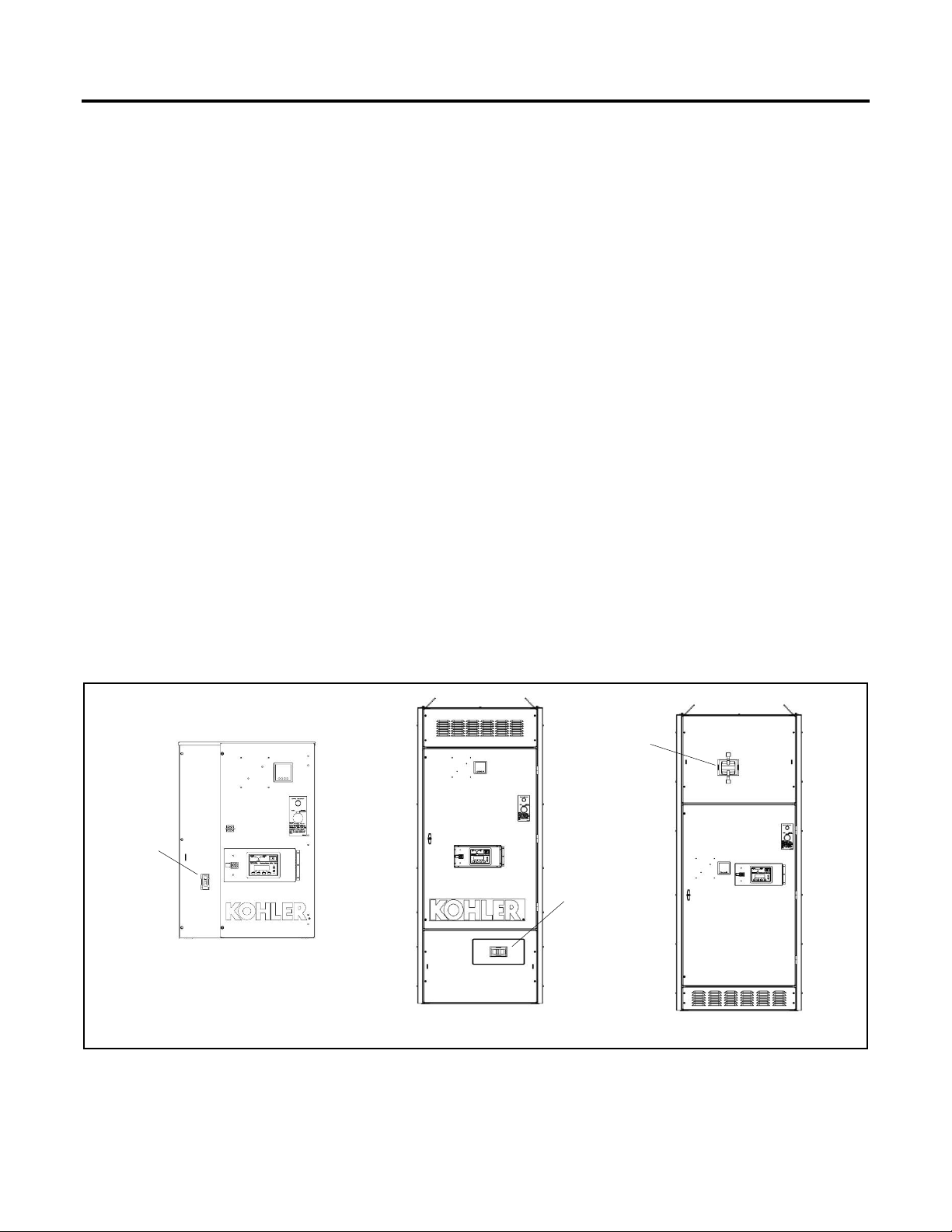
TP-7280 1/24 75
Section 7. Operation
7.1 Transfer Switch Operation
7.1.1 Normal Operation
Under normal conditions, the load is energized from the utility supply. If the utility power fails, the ATS signals the generator to
start (engine start contacts close). The generator controller must be in AUTO mode. The load will be energized by the running
generator.
When utility power is restored, the load is transferred back to the utility source and the engine start signal is removed (contacts
open). If the generator set is in SUTO mode, the engine will stop. There may be a cooldown period before the engine stops.
Refer to the controller operation manual for the sequence of operation.
In the normal operating mode, the service disconnect switch must be in the AUTO position. See the Service Disconnect
Operation section for service disconnect instructions.
7.1.2 Overcurrent Trip
If the utility source circuit breaker trips open due to an overcurrent condition, the ATS controller will initiate an engine start signal
and initiate transfer of the load to the generator supply. A Source1 breaker trip fault will be displayed on the ATS controller. The
utility source will be locked out and the load will remain on the generator supply until the fault is manually reset.
Note:
Contact your local distributor/dealer to identify and correct the cause of the overcurrent condition before resetting the fault.
The utility circuit breaker is located on the front of the ATS. On NEMA Type 1 enclosures, the circuit breaker can be reset without
opening the ATS enclosure. For other enclosure types, open the outer enclosure door to access the circuit breaker handle. See
Figure 64 for typical circuit breaker locations. To reset the circuit breaker, move the handle to OFF (0), and then ON (I). Some
breakers have a handle that can fold down when not in use. Lift the handle before moving it to OFF. Fold the handle back down
after moving it to ON.
After resetting the tripped breaker, check the controller display for fault messages. See the ATS controller operation manual for
instructions to reset the fault. See the List of Related Materials in the Introduction section for the manual part number.
Figure 64 Utility Circuit Breaker Locations, Typical
70-225 Amps
1600-3000 Amps
150-600 Amps
Utility Circuit
Breaker
Utility Circuit
Breaker
Utility Circuit
Breaker
Page 76
76 TP-7280 1/24
7.1.3 Energy Reduction Maintenance Setting (ERMS) System
DANGER
Hazardous voltage.
Will cause severe injury or death.
This equipment must be installed and serviced by qualified electrical personnel.
Servicing the transfer switch. Hazardous voltage will cause severe injury or death. Deenergize all power sources before
servicing. Turn off the main circuit breakers of all transfer switch power sources and disable all generator sets as follows: (1)
Press the generator set off/reset button to shut down the generator set. (2) Disconnect power to all battery chargers. (3)
Disconnect all battery cables, negative (–) leads first. Reconnect negative (–) leads last when reconnecting the battery cables
after servicing. Follow these precautions to prevent the starting of generator sets by an automatic transfer switch, remote
start/stop switch, or engine start command from a remote computer. Before servicing any components inside the enclosure: (1)
Remove all jewelry. (2) Stand on a dry, approved electrically insulated mat. (3) Test circuits with a voltmeter to verify that they
are deenergized.
The Energy Reduction Maintenance Setting (ERMS) system is available as optional, factory-installed equipment on 1200 Amp
and larger model KUS and KUP service entrance rated automatic transfer switches (ATS). The ERMS system is used to reduce
the arc flash incident energy (AFIE) during energized service.
The system can help provide compliance with NEC requirements for arc flash reduction. Refer to the NEC and follow all
applicable codes and regulations during the ATS installation.
The ERMS system is available on MicroLogic P or H trip units with the blue ERMS label shown in Figure 65. See the KUS/KUP
Specification Sheet for circuit breaker information.
Figure 65 ERMS Label on Circuit Breaker Trip Unit
The ERMS module is manufactured by the circuit breaker manufacturer and is used to reduce the tripping threshold and clearing
time. The ERMS is installed and wired at the factory according to the circuit breaker manufacturer’s instructions. Factory
connections are shown in Figure 67 for reference only. No customer connections to the system are required.
The following components are mounted on the ATS enclosure door as shown in Figure 66.
• ERMS Maintenance Mode ON/OFF selector switch.
• Maintenance mode indicator light. The light is ON when the circuit breaker is in ERMS mode.
The I/O Module factory setting = 3; do not change this setting.
NHA67346
Page 77
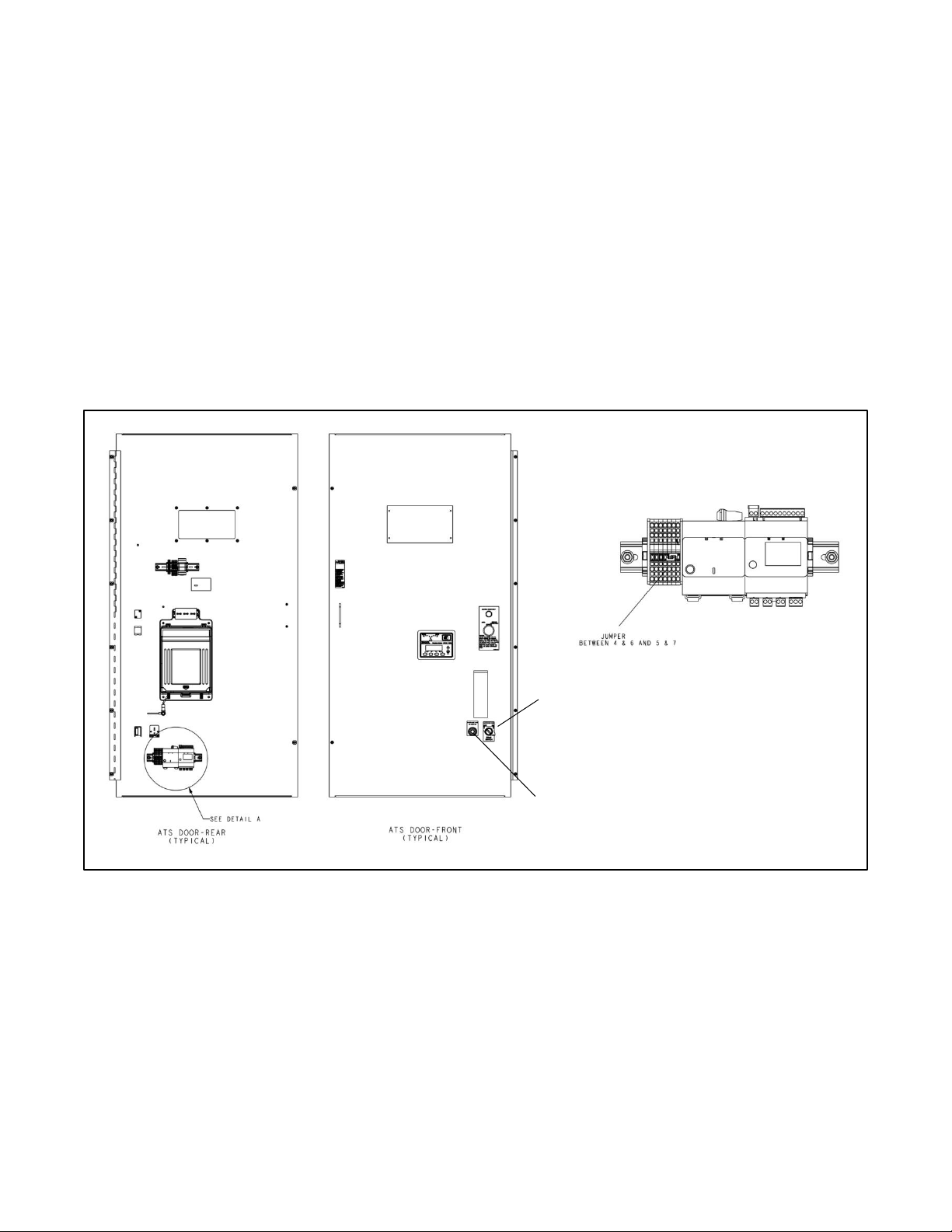
TP-7280 1/24 77
ERMS System Operation Description
When the ERMS switch is “ON” (circuit breaker is in maintenance mode), the circuit breaker’s ERMS instantaneous pickup is
set to the pre-programmed level which is less than the normal instantaneous pickup setting as set by the rotary switch setting
(Ii). As a result, the potential for nuisance tripping increases. Nuisance tripping can be caused by a motor starting, transformer
inrush, or some other momentary power disturbance.
For more information, refer to the ERMS system manufacturer’s literature included with the transfer switch.
ERMS Operation Instructions
1. Turn the ERMS maintenance mode switch to ON before performing service or maintenance on the transfer switch or
downstream equipment.
Note:
Utility source voltage is still present! The ERMS system does not disconnect power or trip/open the utility circuit breaker.
2. After the service procedures are complete, turn the switch OFF for normal system operation.
Note:
Be sure to follow all safety precautions and instructions, including instructions to disconnect power and/or disable the generator
set, when performing maintenance and service procedures on the power system or connected equipment.
Figure 66 ERMS System Components
GM120996
DETAIL A
ERMS Status Indicator
ERMS Maintenance Switch
Page 78
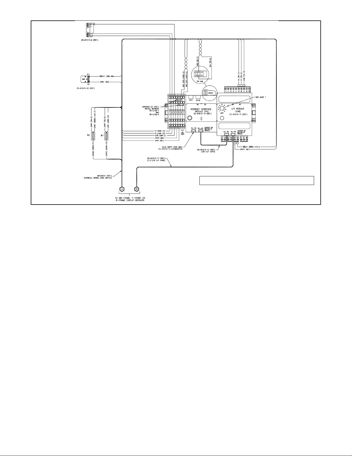
78 TP-7280 1/24
Figure 67 ERMS wiring ( factory-installed)
GM121000
NOTES:
1. The I/O Module is factory-set to APP value 3 for ERMS application.
Page 79
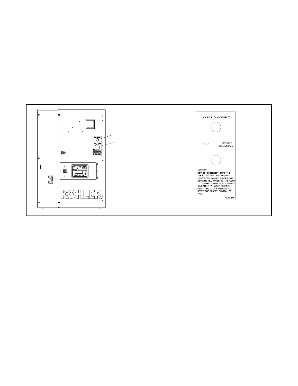
TP-7280 1/24 79
7.2 Service Disconnect Switch Operation
The two-position service disconnect switch trips the utility-side circuit breaker using the shunt trip.
The service disconnect switch and utility disconnected lamp are located on the front door or front panel. See Figure 58 for the
typical service disconnect switch location.
The switch has two positions, AUTO and SERVICE DISCONNECT.
• When the switch is in the AUTO position, the ATS is in normal operation mode
• When the switch is in the SERVICE DISCONNECT position, the ATS service entrance breaker is shunt-tripped and
open. The lamp is illuminated, and the controller display shows SERVICE DISCONNECT.
Note:
The ATS does not signal the generator set to start when the utility-side breaker is tripped.
Figure 68 Service Disconnect Switch Location (typical)
Important notes about service disconnect operation:
• On service entrance transfer switches, the line side lugs are always powered.
• Service disconnect removes power from the load and transfer is inhibited. Power will not be restored to the load until
the switch is returned to AUTO.
• The engine start signal is not activated by the service disconnect procedure.
• Moving the switch to the SERVICE DISCONNECT position during a test or exercise sequence ends the test or exercise
sequence. The engine stops immediately without running a cooldown cycle.
• Controller power. To remove the controller for maintenance or service without interrupting the power to the load, an
optional Controller Disconnect Switch is required. See the Controller Disconnect Switch Operation section for
instructions.
ADV-9983
Utility disconnected lamp
Service disconnect switch
Decal Detail
Page 80
80 TP-7280 1/24
DANGER
Hazardous voltage.
Will cause severe injury or death.
Only authorized personnel should open the enclosure.
WARNING
Accidental starting.
Can cause severe injury or death.
Disconnect the battery cables before working on the generator set. Remove the
negative (–) lead first when disconnecting the battery. Reconnect the negative (–)
lead last when reconnecting the battery.
Servicing the transfer switch. Hazardous voltage will cause severe injury or death. Deenergize all power sources before
servicing. Turn off the main circuit breakers of all transfer switch power sources and disable all generator sets as follows: (1)
Press the generator set off/reset button to shut down the generator set. (2) Disconnect power to all battery chargers. (3)
Disconnect all battery cables, negative (–) leads first. Reconnect negative (–) leads last when reconnecting the battery cables
after servicing. Follow these precautions to prevent the starting of generator sets by an automatic transfer switch, remote
start/stop switch, or engine start command from a remote computer. Before servicing any components inside the enclosure: (1)
Remove all jewelry. (2) Stand on a dry, approved electrically insulated mat. (3) Test circuits with a voltmeter to verify that they
are deenergized.
7.2.1 Service Disconnect Procedure
The service disconnect switch has two positions: AUTO and SERVICE DISCONNECT. Follow the procedures in this section
carefully and observe the safety precautions when performing a service disconnect before maintenance or service. Watch the
LED indicators on the ATS controller to check the ATS position and source status during the procedures.
Note:
The service disconnect procedure removes power from the load, but utility power is still present at the transfer switch normal
side lugs whenever the utility source is available.
Service Disconnect when the Transfer Switch is in NORMAL
Use this procedure if utility power is connected and the transfer switch is in the Normal position.
1. Move the service disconnect control switch located on the door of the transfer switch to the SERVICE DISCONNECT
position. This opens the utility circuit breaker through the shunt trip circuit and sends a fault to the generator set
controller.
2. Verify the following:
• The utility (normal) breaker is open.
• The generator set controller displays a fault message and the generator set is not running.
• The ATS controller display shows SERVICE DISCONNECTED
• The Utility Disconnected light is illuminated and the NOT IN AUTO LED is flashing.
Note:
The External Battery Supply Module (EBSM) allows the generator set battery to continue to supply DC power to the
ATS controller after the Utility source is disconnected. The EBSM (sometimes referred to as the Battery Option Board,
BOB) is factory-installed standard equipment on KUS and KUP models.
3. Attach a safety lockout padlock to the service disconnect control switch to prevent unauthorized reconnection of utility
power. Verify the transfer switch door is closed and locked. If the door is not locked, turn and remove the door key.
4. Use a voltmeter to verify that power is disconnected from the load before servicing connected equipment.
Page 81

TP-7280 1/24 81
Service Disconnect when the Transfer Switch is in EMERGENCY
Use this procedure if the transfer switch is in the Emergency position.
1. Move the service disconnect control switch located on the door of the transfer switch to the SERVICE DISCONNECT
position. This opens the utility circuit breaker through the shunt trip circuit and sends a fault to the generator set
controller.
2. The engine start signal is removed.
3. Wait for the generator set to shut down. The generator set may continue to run for several minutes to cool the engine.
4. Verify the following:
• The utility (normal) breaker is open.
• The generator set controller displays a fault message and the generator set is not running.
• The ATS controller display shows SERVICE DISCONNECTED
• The Utility Disconnected light is illuminated and the NOT IN AUTO LED is flashing.
Note:
The External Battery Supply Module (EBSM) allows the generator set battery to continue to supply DC power to the
ATS controller after the Utility source is disconnected. The EBSM (sometimes referred to as the Battery Option Board,
BOB) is factory-installed standard equipment on KUS and KUP models.
5. Attach a safety lockout padlock to the service disconnect control switch to prevent unauthorized reconnection of utility
power. Verify the transfer switch door is closed and locked. If the door is not locked, turn and remove the door key.
6. Use a voltmeter to verify that power is disconnected from the load before servicing connected equipment.
7.2.2 Service Reconnect Procedure
Service reconnect procedure with Normal source available
1. Remove the padlock from the service disconnect control switch and move the service disconnect switch to the AUTO
position. The Service Disconnect light on the door should turn off. The MPAC 1500 ATS controller will resume normal
operation.
2. Manually reset the utility-side circuit breaker by moving the breaker handle to fully OFF and then ON.
3. If the ATS controller displays shows “FAILURE TO ACQUIRE,” proceed to step 4. Otherwise, go to step 5.
4. Reset the fault on the ATS controller. See the Decision-Maker® MPAC 1500 Operation Manual for instructions, if
necessary.
5. If the ATS is not in the normal position, it will transfer to the normal source.
6. Reset the fault on the generator set controller. See the generator controller Operation Manual for instructions to reset
the fault and prepare the generator set for operation. Then place the generator set controller in AUTO
7. Verify that the ATS controller display shows normal source available and ATS in normal position.
Page 82
82 TP-7280 1/24
Service reconnect procedure when Normal source is NOT available
1. Remove the padlock from the service disconnect control switch and move the service disconnect switch to the AUTO
position. The Service Disconnect light on the door should turn off. The MPAC 1500 ATS controller will resume normal
operation.
2. Manually reset the utility-side circuit breaker by moving the breaker handle to fully OFF and then ON.
3. Reset the fault on the generator set controller. See the generator controller Operation Manual for instructions to reset
the fault and prepare the generator set for operation. Then place the generator set controller in AUTO.
WARNING
The generator set will start when the controller is placed in AUTO.
4. Reset any faults on the ATS controller. See the Decision-Maker® MPAC 1500 Operation Manual for instructions, if
necessary.
5. Verify that the ATS controller display shows emergency source available and ATS in emergency position.
Page 83
7.3 Controller Disconnect Switch Operation
WARNING
Accidental starting.
Can cause severe injury or death.
Disconnect the battery cables before working on the generator set. Remove the
negative (–) lead first when disconnecting the battery. Reconnect the negative (–)
lead last when reconnecting the battery.
DANGER
Hazardous voltage.
Will cause severe injury or death.
Only authorized personnel should open the enclosure.
Disabling the generator set. Accidental starting can cause severe injury or death. Before working on the generator set or
equipment connected to the set, disable the generator set as follows: (1) Press the generator set off/reset button to shut down
the generator set. (2) Disconnect the power to the battery charger, if equipped. (3) Remove the battery cables, negative (–) lead
first. Reconnect the negative (–) lead last when reconnecting the battery. Follow these precautions to prevent the starting of the
generator set by the remote start/stop switch.
The optional controller disconnect switch allows disconnection of the power to the controller during maintenance and service.
See Figure 69.
Note:
On service entrance models, power is always present on the utility side of the ATS. The service disconnect procedure removes
power from the load, but utility power is still present at the transfer switch lugs whenever the utility source is available.
Note:
Disconnecting power to the controls will cause the ATS to send an engine start signal to the generator set. Disable the generator
set before using the controller disconnect switch to disconnect power to the ATS controls.
Operation Instructions
The switch has two positions, auto (I) and disconnect (0).
1. Disable the generator set to prevent starting. Refer to the generator set documentation for specific instructions, if
necessary.
2. Move the controller disconnect switch to the 0 position to disconnect power to the ATS controller.
3. After maintenance or service, move the controller disconnect switch to the I position to reconnect power.
4. Follow the instructions in the generator set documentation to reenable the generator set.
TP-7280 1/24 83
Page 84
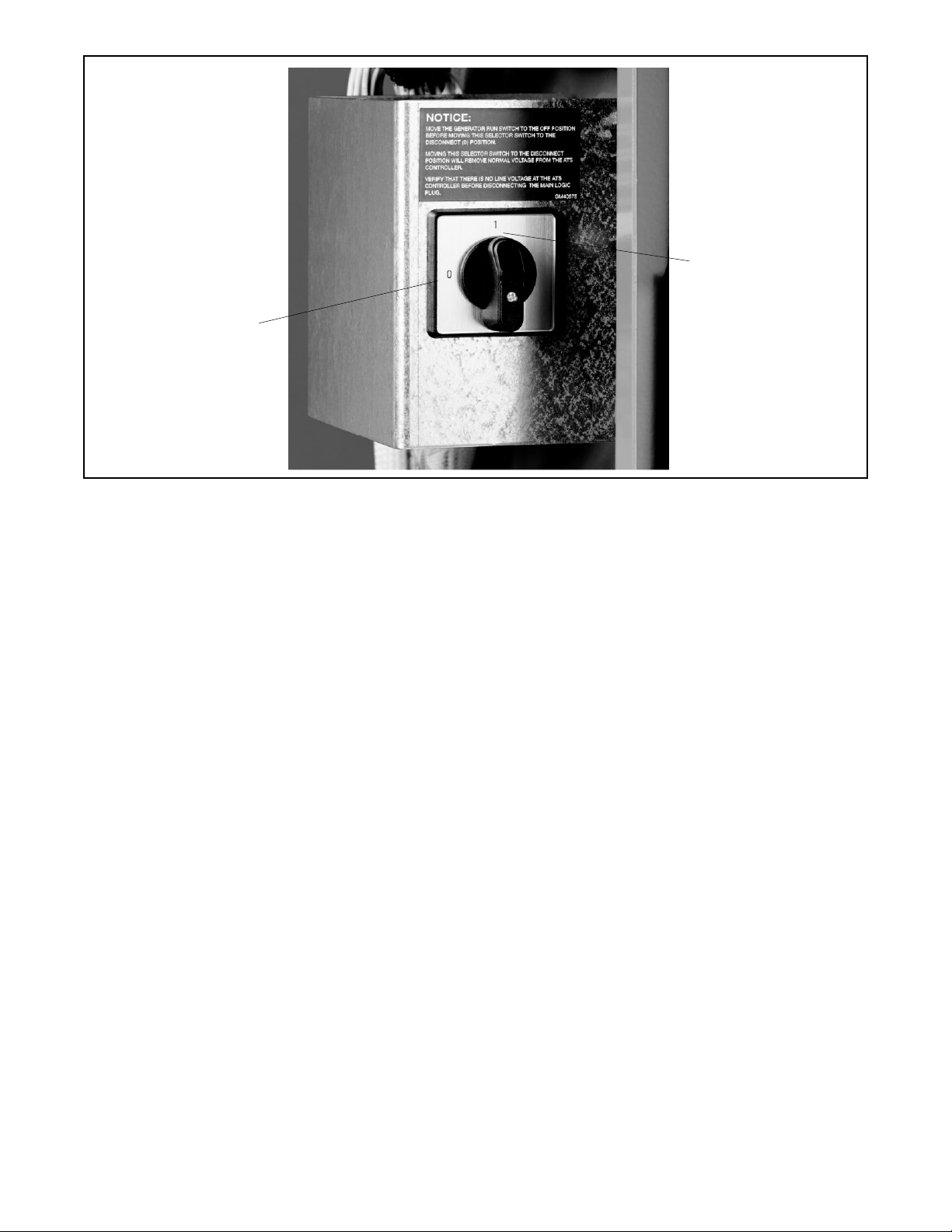
84 TP-7280 1/24
Figure 69 Controller Disconnect Switch
I = Connect
0 = Disconnect
Page 85

TP-7280 1/24 85
Appendix A. Abbreviations
The following list contains abbreviations that may appear in this publication.
A, amp
ampere
CID
cubic inch displacement
FHM
flat head machine (screw)
ABDC
after bottom dead center
CL
centerline
fl. oz.
fluid ounce
AC
alternating current
cm
centimeter
flex.
flexible
A/D
analog to digital
CMOS
complementary metal oxide
freq.
frequency
ADC
advanced digital control;
substrate (semiconductor)
FS
full scale
analog to digital converter
com
communications (port)
ft.
foot, feet
adj.
adjust, adjustment
coml
commercial
ft. lb.
foot pounds (torque)
ADV
advertising dimensional
Coml/Re
Commercial/Recreational
ft./min.
feet per minute
Ah
amp-hour
conn.
connection
ftp
file transfer protocol
AHWT
anticipatory high water
cont.
continued
g
gram
temperature
CPVC
chlorinated polyvinyl chloride
ga.
gauge (meters, wire size)
AISI
American Iron and Steel
crit.
critical
gal.
gallon
ALOP
anticipatory low oil pressure
CSA
Canadian Standards Association
gen.
generator
alt.
alternator
CT
current transformer
genset
generator set
Al
aluminum
Cu
copper
GFI
ground fault interrupter
ANSI
American National Standards
cUL
Canadian Underwriter’s
GND,
ground
Institute (formerly American
Laboratories
gov.
governor
Standards Association, ASA)
CUL
Canadian Underwriter’s
gph
gallons per hour
AO
anticipatory only
Laboratories
gpm
gallons per minute
APDC
Air Pollution Control District
cu. in.
cubic inch
gr.
grade, gross
API
American Petroleum Institute
cw.
clockwise
GRD
equipment ground
approx.
approximate, approximately
CWC
city water-cooled
gr. wt.
gross weight
APU
Auxiliary Power Unit
cyl.
cylinder
H x W x D
height by width by depth
AQMD
Air Quality Management
D/A
digital to analog
HC
hex cap
AR
as required, as requested
DAC
digital to analog converter
HCHT
high cylinder head
AS
as supplied, as stated, as
dB
decibel
HD
heavy duty
suggested
dB(A)
decibel (A weighted)
HET
high exhaust temp., high
ASE
American Society of Engineers
DC
direct current
temp.
ASME
American Society of
DCR
direct current resistance
hex
hexagon
Engineers
deg., °
degree
Hg
mercury (element)
assy.
assembly
dept.
department
HH
hex head
ASTM
American Society for Testing
dia.
diameter
HHC
hex head cap
Materials
DIN
Deutsches Institut fur Normung
HP
horsepower
ATDC
after top dead center
e. V. (also Deutsche Industrie
hr.
hour
ATS
automatic transfer switch
Normenausschuss)
HS
heat shrink
auto.
automatic
DIP
dual inline package
hsg.
housing
aux.
auxiliary
DPDT
double-pole, double-throw
HVAC
heating, ventilation, and air
avg.
average
DPST
double-pole, single-throw
conditioning
AVR
automatic voltage regulator
DVR
digital voltage regulator
HWT
high water temperature
AWG
American Wire Gauge
E, emer.
emergency (power source)
Hz
hertz (cycles per second)
AWM
appliance wiring material
EBSM
external battery supply module
IBC
International Building Code
bat.
battery
ECM
electronic control module,
IC
integrated circuit
BBDC
before bottom dead center
engine control module
ID
inside diameter, identification
BC
battery charger, battery
E2PROM
EEPROM
IEC
International Electrotechnical
BCA
battery charging alternator
electrically-erasable
Commission
BCI
Battery Council International
programmable read-only
IEEE
Institute of Electrical and
BDC
before dead center
memory
Electronics Engineers
BHP
brake horsepower
EDI
electronic data interchange
IMS
mproved motor starting
blk.
black (paint color), block
EFR
emergency frequency relay
in.
inch
(engine)
e.g.
for example (exempli gratia)
in. H2O
inches of water
blk. htr.
block heater
EG
electronic governor
in. Hg
inches of mercury
BMEP
brake mean effective pressure
EGSA
Electrical Generating Systems
in. lb.
inch pounds
bps
bits per second
Association
Inc.
incorporated
br.
brass
EIA
Electronic Industries Association
ind.
industrial
BTDC
before top dead center
EI/EO
end inlet/end outlet
int.
internal
Btu
British thermal unit
EMI
electromagnetic interference
int./ext.
internal/external
Btu/min.
British thermal units per minute
emiss.
emission
I/O
input/output
C
Celsius, centigrade
eng.
engine
IP
internet protocol
cal.
calorie
EPA
Environmental Protection
ISO
International Organization for
CAN
controller area network
Agency
Standardization
CARB
California Air Resources Board
EPS
emergency power system
J
joule
CAT5
Category 5 (network cable)
ER
emergency relay
JIS
Japanese Industry Standard
CB
circuit breaker
ERMS
energy reduction maintenance setting
k
kilo (1000)
CC
crank cycle
ES
engineering special, engineered
K
kelvin
cc
cubic centimeter
special, engine start
kA
kiloampere
CCA
cold cranking amps
ESD
electrostatic discharge
KB
kilobyte (210 bytes)
ccw.
counterclockwise
est.
estimated
KBus
Kohler communication
CEC
Canadian Electrical Code
E-Stop
emergency stop
kg
kilogram
cert.
certificate, certification,
etc.
et cetera (and so forth)
kg/cm2
kilograms per square
cfh
cubic feet per hour
exh.
exhaust
kgm
kilogram-meter
cfm
cubic feet per minute
ext.
external
kg/m3
kilograms per cubic meter
CG
center of gravity
F
Fahrenheit, female
kHz
kilohertz
Page 86

86 TP-7280 1/24
kJ
kilojoule
NPSC
National Pipe, Straight-coupling
SPDT
single-pole, double-throw
km
kilometer
NPT
National Standard taper pipe
SPST
single-pole, single-throw
kOhm,
kilo-ohm
thread per general use
spec
specification
kPa
kilopascal
NPTF
National Pipe, Taper-Fine
specs
specification(s)
kph
kilometers per hour
NR
not required, normal relay
sq.
square
kV
kilovolt
ns
nanosecond
sq. cm
square centimeter
kVA
kilovolt ampere
OC
overcrank
sq. in.
square inch
kVAR
kilovolt ampere reactive
OD
outside diameter
SMS
short message service
kW
kilowatt
OEM
original equipment manufacturer
SS
stainless steel
kWh
kilowatt-hour
OF
overfrequency
std.
standard
kWm
kilowatt mechanical
opt.
option, optional
stl.
steel
kWth
kilowatt-thermal
OS
oversize, overspeed
tach.
tachometer
L
liter
OSHA
Occupational Safety and Health
TB
terminal block
LAN
local area network
Administration
TCP
transmission control protocol
L x W x
length by width by height
OV
overvoltage
TD
time delay
lb.
pound, pounds
oz.
ounce
TDC
top dead center
lbm/ft3
pounds mass per cubic feet
p., pp.
page, pages
TDEC
time delay engine cooldown
LCB
line circuit breaker
PC
personal computer
TDEN
time delay emergency to
LCD
liquid crystal display
PCB
printed circuit board
TDES
time delay engine start
LED
light emitting diode
pF pic
picofarad
TDNE
time delay normal to
Lph
liters per hour
PF
power factor
TDOE
time delay off to emergency
Lpm
liters per minute
ph., Ø
phase
TDON
time delay off to normal
LOP
low oil pressure
PHC
Phillips® head Crimptite®
temp.
temperature
LP
liquefied petroleum
(screw)
term.
terminal
LPG
liquefied petroleum gas
PHH
Phillips® hex head (screw)
THD
total harmonic distortion
LS
left side
PHM
pan head machine (screw)
TIF
telephone influence factor
Lwa
sound power level, A weighted
PLC
programmable logic control
tol.
tolerance
LWL
low water level
PMG
permanent magnet generator
turbo.
turbocharger
LWT
low water temperature
pot
potentiometer, potential
typ.
typical (same in multiple
m
meter, milli (1/1000)
ppm
parts per million
locations)
M
mega (106 when used with SI
PROM
programmable read-only
UF
underfrequency
units), male
memory
UHF
ultrahigh frequency
m3
cubic meter
psi
pounds per square inch
UIF
user interface
m3/hr.
cubic meters per hour
psig
pounds per square inch gauge
UL
Underwriter’s Laboratories,
m3/min.
cubic meters per minute
pt.
pint
UNC
unified coarse thread (was
mA
milliampere
PTC
positive temperature coefficient
UNF
unified fine thread (was NF)
man.
manual
PTO
power takeoff
univ.
universal
max.
maximum
PVC
polyvinyl chloride
URL
uniform resource locator (web
MB
megabyte (220 bytes)
qt.
quart, quarts
address)
MCCB
molded-case circuit breaker
qty.
quantity
US
undersize, underspeed
MCM
one thousand circular mils
R
replacement (emergency) power
UV
ultraviolet, undervoltage
meggar
megohmmeter
source
V
volt
MHz
megahertz
rad.
radiator, radius
VAC
volts alternating current
mi.
mile
RAM
random access memory
VAR
voltampere reactive
mil
one one-thousandth of an inch
RBUS
RS-485 proprietary
VDC
volts direct current
min.
minimum, minute
communications
VFD
vacuum fluorescent display
misc.
miscellaneous
RDO
relay driver output
VGA
video graphics adapter
MJ
megajoule
ref.
reference
VHF
very high frequency
mJ
millijoule
rem.
remote
W
watt
mm
millimeter
Res/Com
Residential/Commercial
WCR
withstand and closing rating
mOhm,m
milliohm
RFI
radio frequency interference
w/
with
MOhm,M
megaohm
RH
round head
WO
write only
MOV
metal oxide varistor
RHM
round head machine (screw)
w/o
without
MPa
megapascal
rly.
relay
wt.
weight
mpg
miles per gallon
rms
root mean square
xfmr
transformer
mph
miles per hour
rnd.
round
MS
military standard
RO
read only
ms
millisecond
ROM
read only memory
m/sec.
meters per second
rot.
rotate, rotating
mtg.
mounting
rpm
revolutions per minute
MTU
Motoren-und Turbinen-Union
RS
right side
MW
megawatt
RTDs
Resistance Temperature
mW
milliwatt
Detectors
µF
microfarad
RTU
remote terminal unit
N, norm.
Normal (power source)
RTV
room temperature vulcanization
NA
not available, not applicable
RW
read/write
nat. gas
natural gas
SAE
Society of Automotive Engineers
NBS
National Bureau of Standards
s, sec.
second
NC
normally closed
RW
read/write
NEC
National Electrical Code
SAE
Society of Automotive Engineers
NEMA
National Electrical
SI
Systeme international d’unites,
Manufacturers Association
International System of Units
NFPA
National Fire Protection
SI/EO
side in/end out
Association
sil.
silencer
Nm
newton meter
SMTP
simple mail transfer protocol SN
NO
normally open
SI/EO
side in/end out
no., nos.
number, numbers
SNMP
simple network management
NPS
National Pipe, Straight
protocol
Page 87

Page 88

TP-7280 1/24
Original Instructions (English)
© 2024 Kohler Co. All rights reserved.
KOHLER CO. Kohler, Wisconsin 53044
Phone 920-457-4441, Fax 920-459-1646
For the nearest sales/service outlet in the
US and Canada, phone 1-800-544-2444
KOHLERPower.com
 Loading...