

Kohler KT3144MSN Installation Manual

FINIAL FUNDAMENTALS
BATH/DECK-MOUNT BATH FAUCET
K-T314, K-T314M, K-T333, K-T333M
1. BEFORE YOU BEGIN
HOW TO USE THESE INSTRUCTIONS
Please read these instructions carefully to familiarize
yourself with the required tools, materials, and installation
sequences. Follow the sections that pertain to your
particular installation. This will help you avoid costly
mistakes. In addition to proper installation, read all
operating and safety instructions.
PRODUCT REQUIREMENTS
For roughing-in dimensions, see Fig. #1.
Ensure that any holes drilled in the deck are not
oversized. The spout requires adequate base
material strength. Spout and valve washers must
contact a maximum amount of deck surface. Spout
hole = 1” (2.5cm) maximum; and valve holes =
1-1/2” (3.8cm) maximum.
Finish deck material must fit closely to the
diameters of the plaster guards, especially the
spout plaster guard.
If holes are drilled in the sheet deck material before
placement on the deck, they must match the
plaster guard diameters.
Plaster guard diameters are approximately 1-5/8”
(4.1cm) for the valve, and 13/16” (2.1cm) for the
spout.
Installer-supplied copper tubing is to be 5/8” O.D.
(1/2” nominal).
Provide an access panel to the valves from the
underside of the deck.
Install water hammer arrestors in the supply lines
near the valves.
All information in these instructions is based on the latest
product information available at the time of publication.
Kohler Co. reserves the right to make changes in product
characteristics, packaging, or availability at any time
without notice.
INST ALLER INFORMA TION
Observe all local plumbing and building codes.
Products purchased separately may influence
valve placement and alignment.
Spout will require that the spout supply tube be cut
to the proper length.
Instructions are given for installation with 8”
(20.3cm) centers. For installations wider than 8”
(20.3cm) centers, adjust all roughing-in
dimensions and copper tubing lengths accordingly .
These instructions cover two methods of
installation: installation on finished deck or rim; and
installation on rough (unfinished) deck (to be
covered later with tile or other finish material).
Leave the protective sleeve on the spout supply
tube until the spout is installed. This is an O-ring
sealing surface, which may be damaged if
unprotected.
ORDERING INFORMA TION
Bath/Deck-mount bath faucet:
Cross handles K-T314-3. . . . . . . . . . . . . . . . . . . . . . . . . . .
Lever handles K-T314-4. . . . . . . . . . . . . . . . . . . . . . . . . . .
Tee handles K-T314-6. . . . . . . . . . . . . . . . . . . . . . . . . . . . .
Cross handles K-T333-3. . . . . . . . . . . . . . . . . . . . . . . . . . .
Lever handles K-T333-4. . . . . . . . . . . . . . . . . . . . . . . . . . .
Tee handles K-T333-6. . . . . . . . . . . . . . . . . . . . . . . . . . . . .
1012557-2-A
TOOLS AND MA TERIALS REQUIRED
Open end/adjustable wrenches
Adjustable arc pliers
1/2” Nom. (5/8” O.D.) tubing
Tubing cutter
Hole cutting equipment
Soldering equipment and supplies
Phillips screwdriver
Español, Página 13
Français, Page 25
2001 Kohler Co.
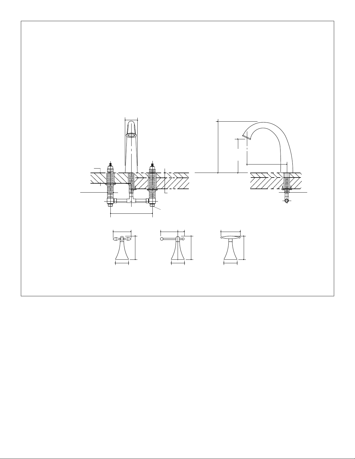
ROUGHING-IN
Turn off the water supply.
Install or relocate the supplies as necessary to conform to
the roughing-in dimensions.
* Dashed lines indicate items to be supplied by the
installer.
Diameter of the spout hole in the deck = 1” (2.5cm).
2-3/8” (6cm)
1/4” (6mm) TO 1-1/4”
1/4” (6mm) TO 2-1/8”
(5.4cm) MAX. RIM OR
DECK MOUNT
1-5/16”
(3.3cm) D.
RIM OR DECK MOUNT
INSTALLATION
8” (20.3cm) Min.
3-3/8” (8.6cm)
(3.2cm) MAX.
FINISHED DECK
3/4” I.D.
3-3/8”
(8.6cm)
Diameter of valve hole in the deck = 1-1/2” (3.8cm).
NOTE: Reinforcing material may be required if the deck or
rim is thin. Install before proceeding.
NOTE: For installations on a rough (unfinished) deck to be
covered later with tile, the tile thickness must not exceed
1-1/4” (3.2cm).
9-1/2”
(24.1cm)
2-1/8” (5.4cm) MAX.
ROUGH DECK
ROUGH + FINISHED
DECK MOUNT INSTALLATION
1-1/4”
(3.2cm)
6-1/4”
(15.9cm)
3-3/4” (9.5cm)
7-1/2”
(19.1cm)
7/8”
(2.2cm) D.
4-1/2”
(11.4cm)
2-1/2” (6.4cm)
2-1/2” (6.4cm)
Fig. #1
4-1/2”
(11.4cm)
4-1/2”
(11.4cm)
2-1/2” (6.4cm)
TEECROSS LEVER
1012557-2-A
2
Kohler Co., Kohler, WI U.S.A.
2. INSTALLATION ON FINISHED DECK OR RIM
NOTE: For installation on rough (unfinished) deck,
proceed to Section 3.
Preparation: For installations with 8” (20.3cm) centers
using copper tubing (1/2” nominal, 5/8” O.D.), cut the
tubing to the lengths as follows:
2 pieces: 2-7/8” (7.3cm) long
1 piece: 2-3/8” (6cm) long (for spout supply)
For non-8” (20.3cm) center installations, adjust the
tubing lengths as necessary.
NOTE: Leave the protective sleeve on the spout supply
tube until the spout is installed. This is an O-ring sealing
surface, which may be damaged if unprotected.
Install Spout Supply Tube: Slide a brass washer from
the bottom of the spout supply tube over the threads until
the washer reaches the supply tube shoulder.
Insert the spout supply tube through the mounting hole
from the top of the deck/rim. Ensure that the flat portion
of the washer faces forward. The supply tube will be
suspended by the washer.
Slide a brass washer onto the spout supply tube from the
bottom, and thread on the mounting nut. Tighten the nut.
NOTE: Do not use the supplied wood screws for
installation on finished deck or rim.
Install Valve Bodies: Thread one mounting nut, flange
side up, onto each valve body.
NOTE: Rims less than 1/4” (6mm) thick require two
rubber washers in the following step; other installations
require only one rubber washer.
Slide one fiber washer, followed by one or two rubber
washers, onto each valve body.
Insert the 2-7/8” (7.3cm) long copper tubes between the
valve bodies and the 1/2” tee. Then insert the 2-3/8” (6cm)
long copper tube into the top of the tee.
Spout Supply Tube
Supply Tube Shoulder
2-3/8” (6cm)
Copper Tube
Rubber Washer
or Washers
Fiber Washer
Mounting Nut
Valve Body
Brass Washer
Brass Washer
Nut
Fig. #2
1/2”
Tee
2-7/8” (7.3cm)
Copper Tubes
Fig. #3
DO NOT solder the connections yet.
Kohler Co., Kohler, WI U.S.A.
3
1012557-2-A
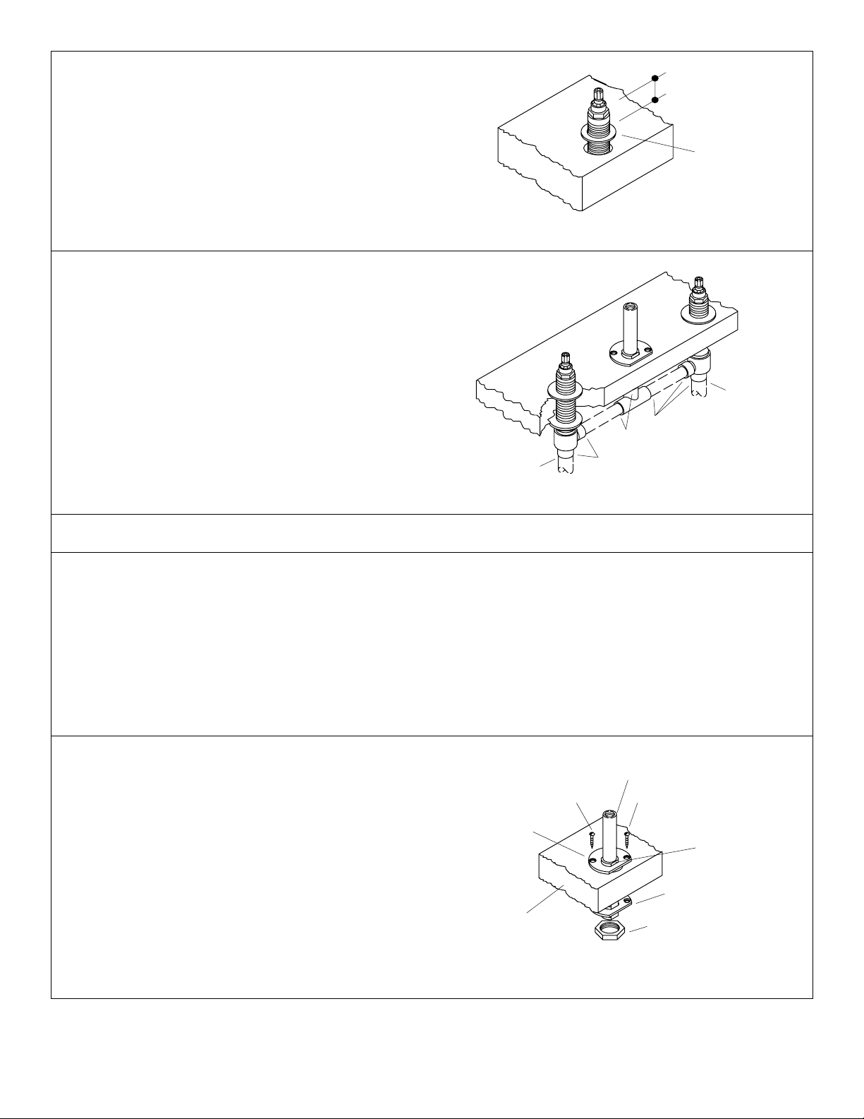
NOTE: Orient the valve body marked “COLD” so it is on
the right when you are facing the front of the faucet.
Insert the valve bodies through the mounting holes from
the bottom of the deck/rim. Mate the copper tube from the
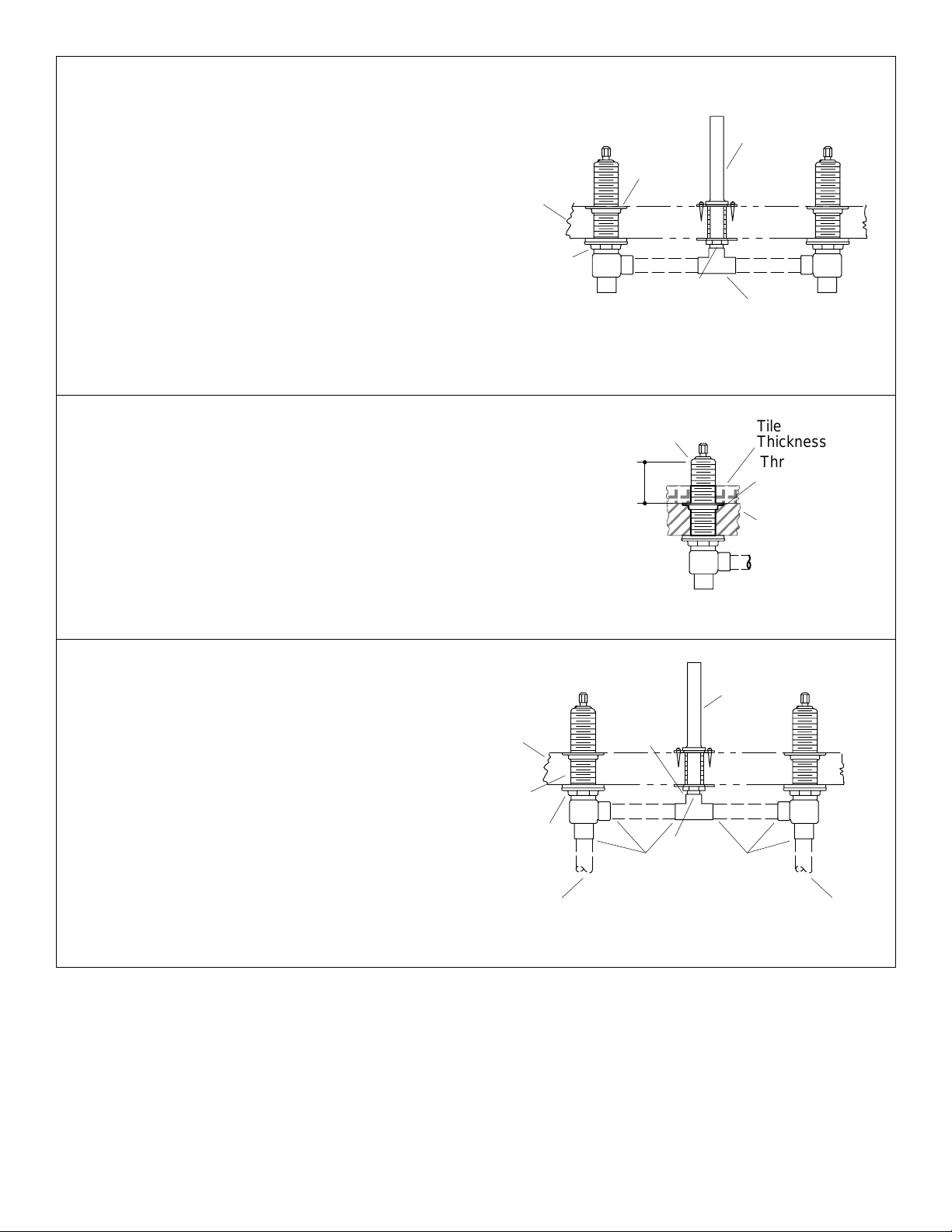
tee with the spout supply tube. Hold in place.
Set a collar, with the flange side up, onto each valve body .
Thread down to at least 1” (2.5cm) from the top thread on
the valve body.
Tighten the mounting nuts on each valve body from
underneath the deck/rim.
Solder the copper tubes to the valve bodies, tee, and
spout supply tube.
Solder the hot and cold water tubes to the valve body
inlets. Ensure that the cold supply is on the right side.
NOTE: Proceed to Section 4.
1” (2.5cm)
Collar
Fig. #4
Cold
Supply
Solder
Solder
Hot
Supply
Solder
Fig. #5
3. INSTALLATION ON ROUGH (UNFINISHED) DECK
Preparation: For installations with 8” (20.3cm) centers
using copper tubing (1/2” nominal, 5/8” O.D.), cut two
pieces of tubing to 2-7/8” (7.3cm) in length.
For non-8” (20.3cm) center installations, adjust the tubing
lengths as necessary.
NOTE: Leave the protective sleeve on the spout supply
tube until the spout is installed. This is an O-ring sealing
surface which may be damaged if unprotected.
Install Spout Supply Tube: Slide a brass washer from
the bottom of the spout supply tube over the threads until
the washer reaches the supply tube shoulder . Ensure that
the countersunk holes in the washer are facing upward.
Insert the spout supply tube through the mounting hole
from the top of the deck. Ensure that the flat portion of
washer faces forward. The supply tube will be suspended
by the washer.
Brass
Washer
Spout Supply Tube
ScrewScrew
Supply Tube
Shoulder
Brass
Washer
Slide a brass washer onto the spout supply tube, and
thread on the mounting nut. Tighten the nut.
Secure the brass washer to the deck using the two
supplied wood screws.
1012557-2-A
Rough
Deck
Fig. #6
4
Nut
Kohler Co., Kohler, WI U.S.A.
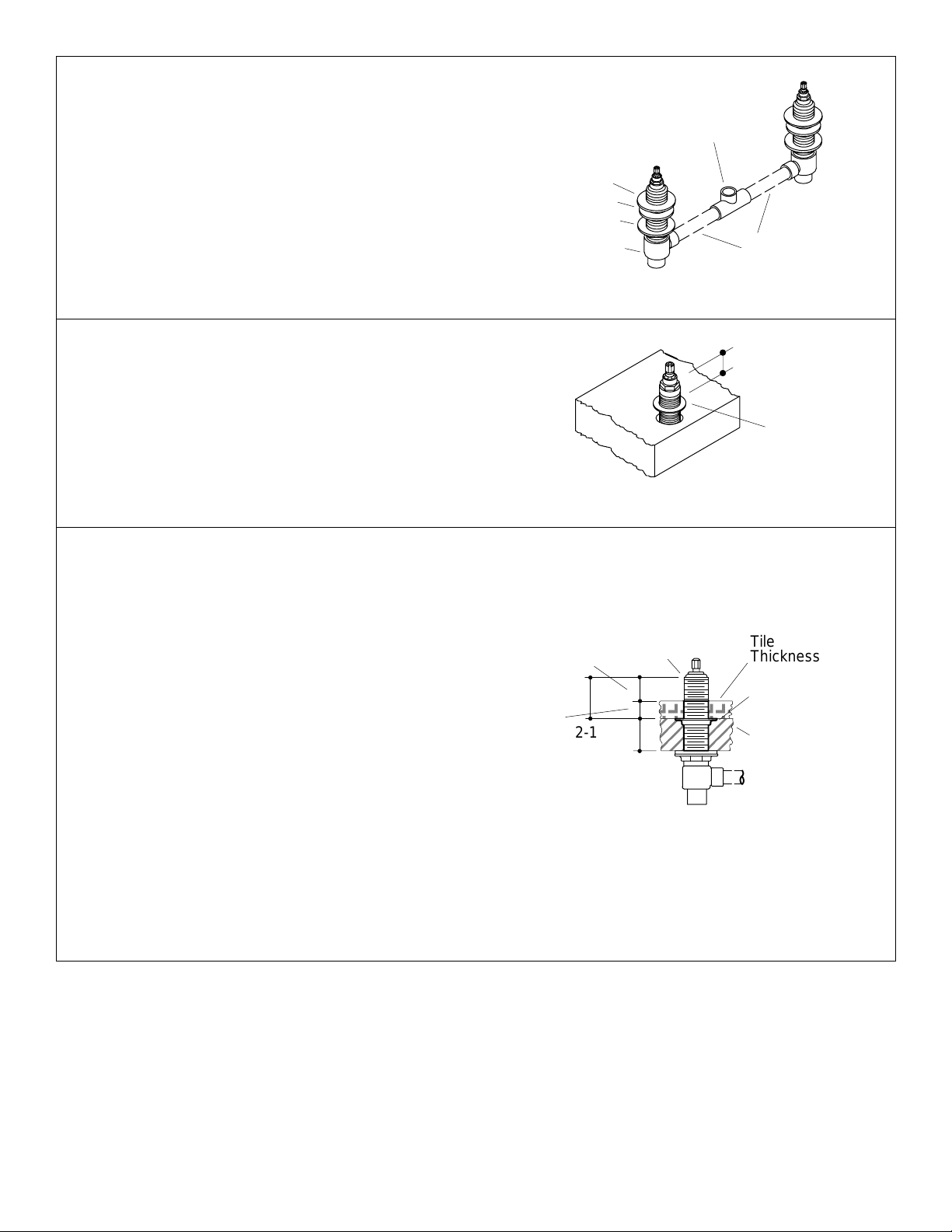
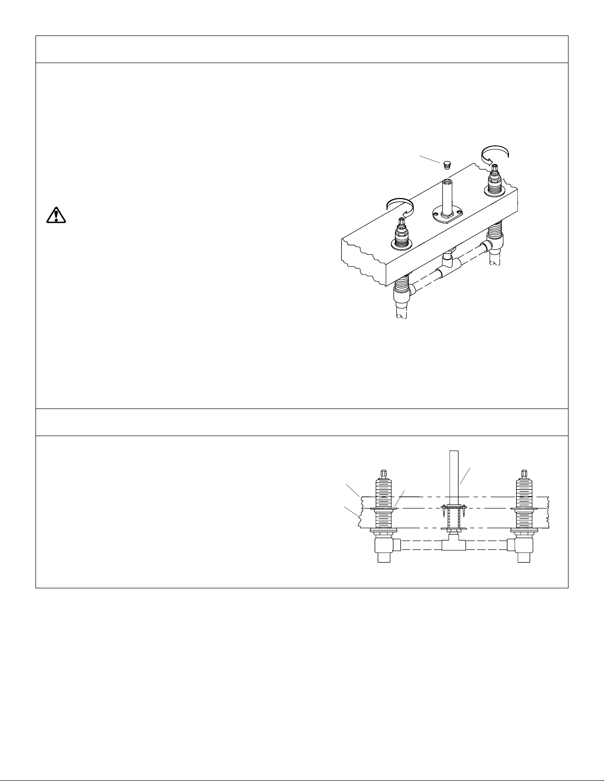
Install Valve Bodies: Thread one mounting nut, flange
side up, followed by one fiber washer and one rubber
washer onto each valve body.
Insert the 2-7/8” (7.3cm) long copper tubes between the
valve bodies and tee.
DO NOT solder the connections yet.
1/2” Tee
Rubber Washer
Fiber Washer
Mounting Nut
NOTE: Orient the valve body marked “COLD” so it is on
the right when facing the front of the faucet.
Insert the valve bodies through the mounting holes from
the bottom of the deck. Mate the copper tube from the tee
with the spout supply tube. Hold in place.
Set a collar, with the flange side up, onto each valve body .
Thread down to at least 1” (2.5cm) from the top thread on
the valve body.
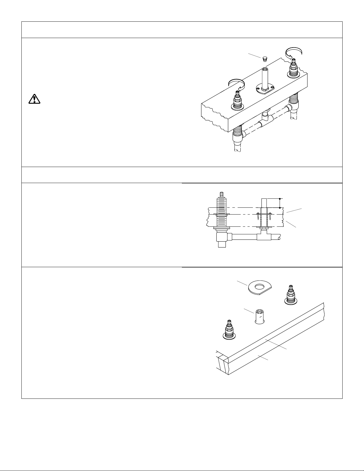
Set Valve Body Height: Use one of the following two
formulas to calculate the valve body clearance required
for the finish material at your site.
Add the tile thickness to 1-1/4” (3.2cm) (distance required
from the finished deck to the top of the valve threads), if
the tile is less than 1” (2.5cm) thick.
Example #1: Tile thickness 3/4” (2cm) + 1-1/4” (3.2cm)
= 2” (5cm) clearance.
If the tile thickness is between 1” (2.5cm) and 1-1/4”
(3.2cm), add only 1” (2.5cm) to the 1-1/4” (3.2cm)
distance.
Valve Body
1-1/4” (3.2cm)
2” (5cm)
3/4” (2cm)
Top of Valve
Threads
2-1/8”
(5.4cm)
Max.
2-7/8” (7.3cm)
Copper Tubes
Fig. #7
1” (2.5cm)
Collar
Fig. #8
Tile
Thickness
Threaded
Collar
Rough
Deck
Example #2: Tile thickness 1” (2.5cm) + 1-1/4” (3.2cm)
= 2-1/4” (5.7cm) clearance.
Adjust the threaded collar until the dimension from the top
of the valve threads to the top of the rough deck surface
equals the clearance requirement you calculated.
Note this dimension. Y ou will need to use it again after
connecting the supply tube.
Kohler Co., Kohler, WI U.S.A.
EXAMPLE #1
Fig. #9
5
1012557-2-A
Supply Tube Connection: Measure the distance from
the bottom of the spout supply tube to the top of the tee.
Add 1” (2.5cm) to this measurement, and cut a piece of
1/2” nominal (5/8” O.D.) copper tubing to fit into the supply
tube and tee port.
Back off the threaded collars as far as possible without
removing them. Pivot the valve bodies enough to remove
the tee and two pieces of tubing. If the valve body holes
are smaller than recommended, it may be necessary to
remove the entire valve body assembly.
Install the tubing into the tee. Mate the copper tube from
the tee with the spout supply tube. Pivot the valve bodies
onto the two pieces of copper tubing.
DO NOT solder at this time.
Reset Valve Body Height: Adjust the threaded collars
until the dimension from the top of the valve threads to the
top of the rough deck surface equals the clearance
requirement you calculated in Fig. #9.
Rough
Deck
Mounting
Nut
Top of Valve Threads
Pre-determined
Clearance
Requirement
Threaded
Collar
Copper
Tube
Fig. #10
Spout
Supply
Tube
Tee
Tile
Thickness
Threaded
Collar
Rough
Deck
Tighten the mounting nuts on each valve body underneath
the deck.
Solder the copper tubes to the valve bodies, tee, and
spout supply tube.
Ensure that the cold supply is on the right side.
Solder the hot and cold water supply tubes to the valve
body inlets.
Rough
Deck
Valve
Body
Mounting
Nut
Hot
Supply
Copper
Tube
Solder
Fig. #11
Spout
Supply
Tube
Solder
Solder
Cold
Supply
Fig. #12
1012557-2-A
6
Kohler Co., Kohler, WI U.S.A.
4. VALVING CHECKOUT (ALL INSTALLATIONS)
Close
Thread a 1/4” pipe plug into the top of the spout supply
tube.
Ensure that the valves are closed (cold - fully
counterclockwise, hot - fully clockwise).
Turn on the main water supply, and check the complete
installation for leaks with the valves closed and open.
Repair leaks as required.
Close both valves. Turn off the main water supply.
WARNING:Risk of personal injury. Lines will be
pressurized. Do not lean over pipe plug when
turning or removing the plug.
Wrap a towel around the pipe plug to prevent water spray .
Water will purge from the supply tube when you remove
the plug.
Carefully back out the pipe plug to relieve pressure.
Thread the pipe plug back into the spout supply tube.
Leave the pipe plug installed until the spout and handle
are installed.
Install the cardboard plaster guards over both valves and
the spout supply tube. Leave in place until the spout and
handle are installed.
5. INSTALL TILE (IF APPLICABLE)
1/4” Pipe Plug
Close
Hot
Close
Cold
Fig. #13
Verify that there will be a 1-1/4” (3.2cm) distance from the
top of the sleeve to the top of the tile. If not, do not install
the tile due to improper valve installation.
If proper clearance exists, install tile up to the plaster
guards on the valves and the spout supply tube.
Tile
Rough
Deck
Threaded
Collar
Fig. #14
Spout
Supply
Tube
Kohler Co., Kohler, WI U.S.A.
7
1012557-2-A
6. BEFORE INSTALLING SPOUT AND HANDLES
REMOVE PIPE PLUG
Ensure that the valves are closed (cold - fully
counterclockwise, hot - fully clockwise).
Turn off the main water supply.
WARNING:Risk of personal injury . Lines may be
pressurized. Do not lean over pipe plug when
turning or removing the plug.
Wrap a towel around the pipe plug to prevent water spray .
Water may purge from the supply tube when you remove
the plug.
Carefully remove the pipe plug.
7. INSTALL SPOUT
Remove the plaster guard from the spout supply tube.
Cut off the spout supply tube 1-1/4” (3.2cm) above the rim,
finished deck, or tile.
1/4” Pipe Plug
Close
Hot
Close
Cold
Fig. #15
1-1/4” (3.2cm)
Tile
Finish
Ensure that all burrs are removed from the supply tube to
prevent damage to the O-ring seal on the sleeve.
NOTE: The following step is applicable to a tile covered
rough deck installation only.
Slide a brass washer, flat side facing forward, onto the
supply tube. The brass washer is furnished with the spout.
NOTE: The washer is not needed for rim/finished deck
installation.
Rough
Deck
Fig. #16
Washer
Spout
Supply
Tube
Finished
Deck
Rough
Deck
Fig. #17
1012557-2-A
8
Kohler Co., Kohler, WI U.S.A.
Back off the setscrews in the sleeve, and with a twisting
motion install the sleeve on the spout supply tube until it
contacts the washer surface.
Align the sleeve so the setscrews are not facing directly
forward or backward.
Sleeve
Setscrew
Tighten the setscrews.
When supplied, position the ring over the sleeve so it rests
upon the washer.
Apply a ring of plumbers putty or other sealant around the
underside of the spout according to the putty
manufacturer’s instructions.
CAUTION: Risk of product damage. Use care
when installing the spout assembly to prevent
damage to the O-ring seal on the sleeve.
Install the spout assembly onto the sleeve, and carefully
press down until the spout base contacts the deck, rim, or
tile.
Align the spout as desired, and tighten the setscrew.
If included, press the plug button into the setscrew hole.
Setscrew
Fig. #18
Spout
Apply Plumbers Putty
Fig. #19
Plug
Button
Setscrew
Kohler Co., Kohler, WI U.S.A.
Fig. #20
9
1012557-2-A
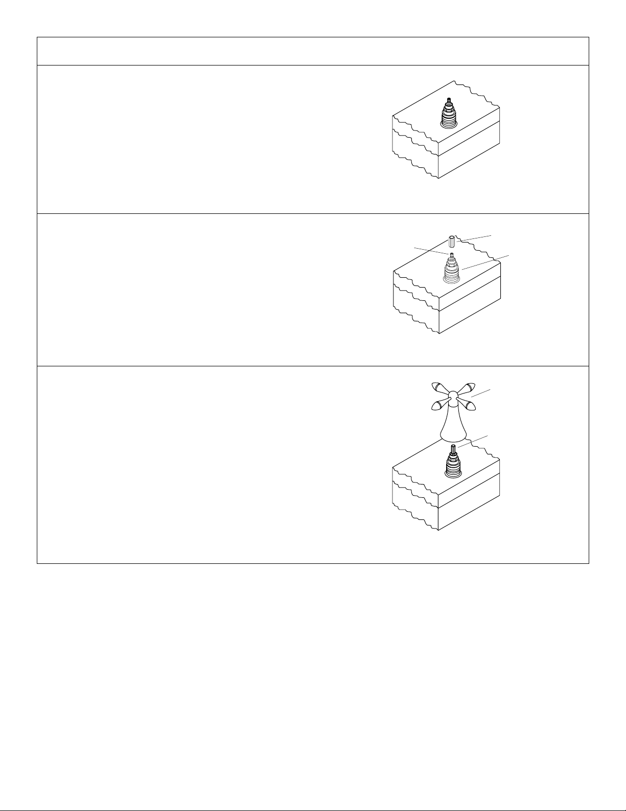
8. INSTALL HANDLES
Remove the plaster guards from the hot and cold valves.
Fig. #21
Install a stem extension onto each valve stem spline.
Ensure that the splines are properly aligned.
NOTE: There are several handle styles available for this
product. For illustrative purposes, only the Cross handle
is shown. Installation of the different handle styles is
identical.
Install the handle assembly by threading onto the valve
body . Take care that the splines inside the skirt and stem
extension are engaged. Adjust as required.
NOTE: The stem extension allows for fine adjustment of
handle alignment. To refine the alignment, unthread the
handle assembly, and reposition the stem extension on
the valve stem. Rethread the handle assembly , and check
the handle alignment. Repeat until the alignment is
satisfactory.
Valve Stem Spline
Stem Extension
Valve Body
Fig. #22
Handle
Assembly
Stem Extension
Fig. #23
1012557-2-A
10
Kohler Co., Kohler, WI U.S.A.
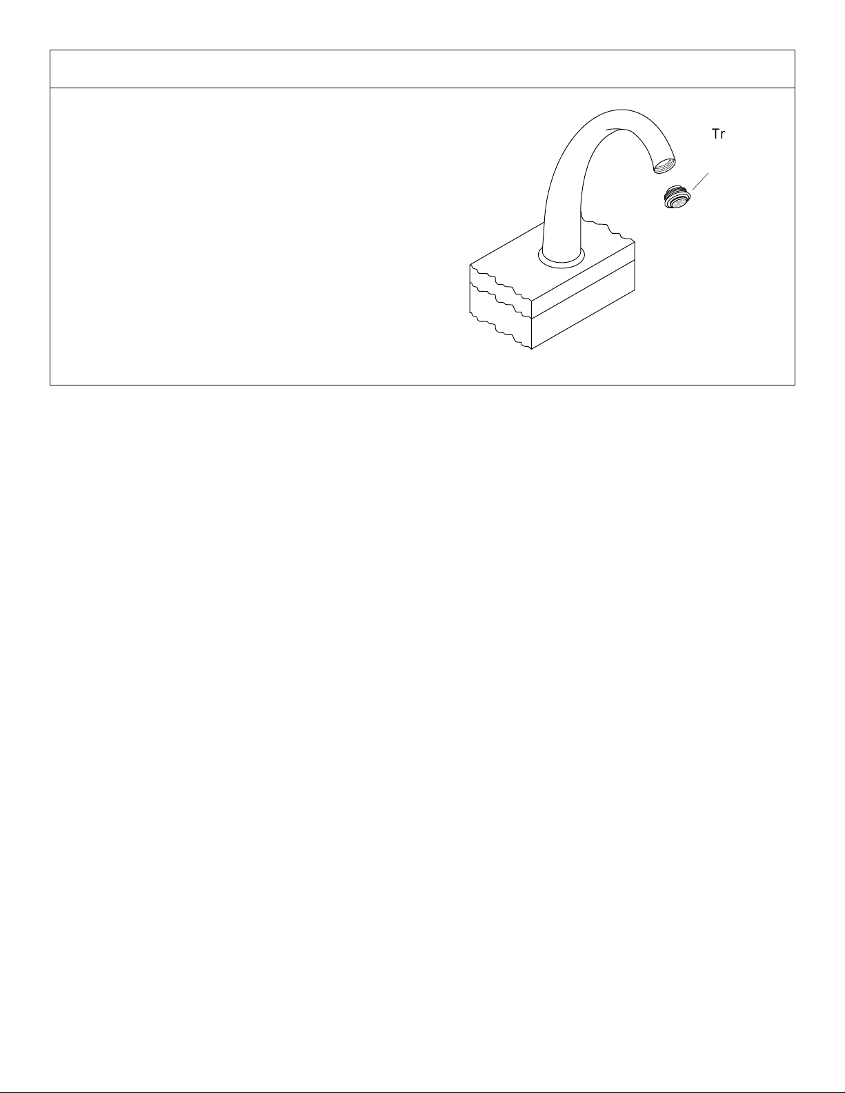
9. INSTALLATION COMPLETION
Ensure that both faucet handles are turned off (hot clockwise close, cold - counterclockwise close).
Turn on the main water supply, and check for leaks.
Repair as required.
Remove the trim ring/aerator assembly . Turn on both hot
and cold valves, and run water through the spout for about
a minute to remove any debris. Check for leaks.
Turn off both hot and cold valves. Reinstall the trim
ring/aerator assembly.
Trim Ring/
Aerator
Assembly
Fig. #24
Kohler Co., Kohler, WI U.S.A.
11
1012557-2-A
 Loading...